US11649136B2 - Conveyance apparatus location determination using probability - Google Patents
Conveyance apparatus location determination using probability Download PDFInfo
- Publication number
- US11649136B2 US11649136B2 US16/266,297 US201916266297A US11649136B2 US 11649136 B2 US11649136 B2 US 11649136B2 US 201916266297 A US201916266297 A US 201916266297A US 11649136 B2 US11649136 B2 US 11649136B2
- Authority
- US
- United States
- Prior art keywords
- period
- conveyance apparatus
- time
- determining
- conveyance
- Prior art date
- Legal status (The legal status is an assumption and is not a legal conclusion. Google has not performed a legal analysis and makes no representation as to the accuracy of the status listed.)
- Active, expires
Links
Images


Classifications
-
- B—PERFORMING OPERATIONS; TRANSPORTING
- B66—HOISTING; LIFTING; HAULING
- B66B—ELEVATORS; ESCALATORS OR MOVING WALKWAYS
- B66B1/00—Control systems of elevators in general
- B66B1/24—Control systems with regulation, i.e. with retroactive action, for influencing travelling speed, acceleration, or deceleration
- B66B1/28—Control systems with regulation, i.e. with retroactive action, for influencing travelling speed, acceleration, or deceleration electrical
-
- B—PERFORMING OPERATIONS; TRANSPORTING
- B66—HOISTING; LIFTING; HAULING
- B66B—ELEVATORS; ESCALATORS OR MOVING WALKWAYS
- B66B1/00—Control systems of elevators in general
- B66B1/34—Details, e.g. call counting devices, data transmission from car to control system, devices giving information to the control system
- B66B1/3492—Position or motion detectors or driving means for the detector
-
- B—PERFORMING OPERATIONS; TRANSPORTING
- B66—HOISTING; LIFTING; HAULING
- B66B—ELEVATORS; ESCALATORS OR MOVING WALKWAYS
- B66B1/00—Control systems of elevators in general
- B66B1/34—Details, e.g. call counting devices, data transmission from car to control system, devices giving information to the control system
- B66B1/3415—Control system configuration and the data transmission or communication within the control system
- B66B1/3423—Control system configuration, i.e. lay-out
-
- B—PERFORMING OPERATIONS; TRANSPORTING
- B66—HOISTING; LIFTING; HAULING
- B66B—ELEVATORS; ESCALATORS OR MOVING WALKWAYS
- B66B1/00—Control systems of elevators in general
- B66B1/34—Details, e.g. call counting devices, data transmission from car to control system, devices giving information to the control system
- B66B1/3415—Control system configuration and the data transmission or communication within the control system
- B66B1/3446—Data transmission or communication within the control system
-
- B—PERFORMING OPERATIONS; TRANSPORTING
- B66—HOISTING; LIFTING; HAULING
- B66B—ELEVATORS; ESCALATORS OR MOVING WALKWAYS
- B66B5/00—Applications of checking, fault-correcting, or safety devices in elevators
- B66B5/0006—Monitoring devices or performance analysers
-
- B—PERFORMING OPERATIONS; TRANSPORTING
- B66—HOISTING; LIFTING; HAULING
- B66B—ELEVATORS; ESCALATORS OR MOVING WALKWAYS
- B66B5/00—Applications of checking, fault-correcting, or safety devices in elevators
- B66B5/0006—Monitoring devices or performance analysers
- B66B5/0018—Devices monitoring the operating condition of the elevator system
- B66B5/0031—Devices monitoring the operating condition of the elevator system for safety reasons
Definitions
- the embodiments herein relate to the field of conveyance systems, and specifically to a method and apparatus for monitoring a conveyance apparatus of a conveyance system.
- Conveyance systems such as, for example, elevator systems, escalator systems, and moving walkways may require periodic monitoring to perform diagnostics.
- a method of monitoring a conveyance apparatus within a conveyance system including: obtaining a starting location position probability distribution of the conveyance apparatus within the conveyance system; detecting motion of the conveyance apparatus away from the probable starting location for a period of time; determining a distance traveled by the conveyance apparatus during the period of time; determining a direction of motion of the conveyance apparatus during the period of time; and determining a probability of the conveyance apparatus being at each of a plurality of possible destination locations at a conclusion of the period of time in response to the starting location position probability distribution and at least one of the distance traveled, the direction of motion, and the period of time.
- determining a distance traveled by the conveyance apparatus during the period of time further includes: detecting an acceleration of the conveyance apparatus during the period of time; and determining the distance travelled by the conveyance apparatus in response to the acceleration and the period of time.
- determining a distance traveled by the conveyance apparatus during the period of time further includes: obtaining a velocity of the conveyance apparatus during the period of time; and determining the distance travelled by the conveyance apparatus in response to the velocity of the conveyance apparatus and the period of time.
- further embodiments may include that obtaining a velocity of the conveyance apparatus during the period of time further includes: detecting a velocity of the conveyance apparatus during the period of time.
- further embodiments may include that the direction of motion of the conveyance apparatus is determined in response to the acceleration of the conveyance apparatus detected during the period of time.
- determining a distance traveled by the conveyance apparatus during the period of time further includes: detecting a first air pressure at the probable starting location of the conveyance apparatus; detecting a second air pressure at the conclusion of the period of time; and determining the distance travelled by the conveyance apparatus in response to the first air pressure and the second air pressure.
- further embodiments may include: activating an alert when the probability of the conveyance apparatus being at each of a plurality of possible destination locations at a conclusion of the period of time is less than a selected probability.
- further embodiments may include that the conveyance system is an elevator system and the conveyance apparatus is an elevator car.
- further embodiments may include: determining the probable destination location, wherein the probable destination location is a possible destination location of the plurality of possible destination locations having the probability that is highest amongst the plurality of possible destination locations.
- a sensing apparatus for monitoring a conveyance apparatus within a conveyance system.
- the sensing apparatus including: a processor; and a memory including computer-executable instructions that, when executed by the processor, cause the processor to perform operations.
- the operations including: determining a starting location position probability distribution of the conveyance apparatus within the conveyance system; detecting motion of the conveyance apparatus away from the probable starting location for a period of time; determining a distance traveled by the conveyance apparatus during the period of time; determining a direction of motion of the conveyance apparatus during the period of time; and determining a probability of the conveyance apparatus being at each of a plurality of possible destination locations at a conclusion of the period of time in response to starting location position probability distribution and at least one of the distance traveled, the direction of motion, and the period of time.
- determining a distance traveled by the conveyance apparatus during the period of time further includes: detecting an acceleration of the conveyance apparatus during the period of time; and determining the distance travelled by the conveyance apparatus in response to the acceleration and the period of time.
- determining a distance traveled by the conveyance apparatus during the period of time further includes: obtaining a velocity of the conveyance apparatus during the period of time; and determining the distance travelled by the conveyance apparatus in response to the velocity of the conveyance apparatus and the period of time.
- further embodiments may include that obtaining a velocity of the conveyance apparatus during the period of time further includes: detecting a velocity of the conveyance apparatus during the period of time.
- further embodiments may include that the direction of motion of the conveyance apparatus is determined in response to the acceleration of the conveyance apparatus detected during the period of time.
- determining a distance traveled by the conveyance apparatus during the period of time further includes: detecting a first air pressure at the probable starting location of the conveyance apparatus; detecting a second air pressure at the conclusion of the period of time; and determining the distance travelled by the conveyance apparatus in response to the first air pressure and the second air pressure.
- further embodiments may include that the operations further include: activating an alert when the probability of the conveyance apparatus being at each of a plurality of possible destination locations at a conclusion of the period of time is less than a selected probability.
- further embodiments may include that the conveyance system is an elevator system and the conveyance apparatus is an elevator car.
- further embodiments may include that the operations further include: determining the probable destination location, wherein the probable destination location is a possible destination location of the plurality of possible destination locations having the probability that is highest amongst the plurality of possible destination locations.
- a computer program product tangibly embodied on a computer readable medium including instructions that, when executed by a processor, cause the processor to perform operations including: determining a starting location position probability distribution of the conveyance apparatus within the conveyance system; detecting motion of the conveyance apparatus away from the probable starting location for a period of time; determining a distance traveled by the conveyance apparatus during the period of time; determining a direction of motion of the conveyance apparatus during the period of time; and determining a probability of the conveyance apparatus being at each of a plurality of possible destination locations at a conclusion of the period of time in response to starting location position probability distribution and at least one of the distance traveled, the direction of motion, and the period of time.
- determining a distance traveled by the conveyance apparatus during the period of time further includes: detecting an acceleration of the conveyance apparatus during the period of time; and determining the distance travelled by the conveyance apparatus in response to the acceleration and the period of time.
- inventions of the present disclosure include determining a probability that a conveyance apparatus of a conveyance system is at a possible destination location based upon distance that the conveyance apparatus has travelled.
- FIG. 1 is a schematic illustration of an elevator system that may employ various embodiments of the present disclosure
- FIG. 2 is a schematic illustration of a sensor system for the elevator system of FIG. 1 , in accordance with an embodiment of the disclosure
- FIG. 3 is a schematic illustration of the location of sensing apparatus of the sensor system of FIG. 2 , in accordance with an embodiment of the disclosure
- FIG. 4 is a schematic illustration of a sensing apparatus of the sensor system of FIG. 2 , in accordance with an embodiment of the disclosure.
- FIG. 5 is a flow chart of a method of monitoring a conveyance apparatus within a conveyance system, in accordance with an embodiment of the disclosure.
- Conveyance systems such as, for example, elevator systems, escalator systems, and moving walkways may require periodic monitoring to perform diagnostics using a variety of sensors.
- the sensors may be one way sensing apparatus that only communicate data rather than receiving data, thus saving power.
- Such sensing apparatus may require a location of the conveyance system to supplement detected data and must detect the location of the conveyance system by itself.
- the tracked location may become uncertain at times and embodiments disclosed herein seek to address this issue.
- FIG. 1 is a perspective view of an elevator system 101 including an elevator car 103 , a counterweight 105 , a tension member 107 , a guide rail 109 , a machine 111 , a position reference system 113 , and a controller 115 .
- the elevator car 103 and counterweight 105 are connected to each other by the tension member 107 .
- the tension member 107 may include or be configured as, for example, ropes, steel cables, and/or coated-steel belts.
- the counterweight 105 is configured to balance a load of the elevator car 103 and is configured to facilitate movement of the elevator car 103 concurrently and in an opposite direction with respect to the counterweight 105 within an elevator shaft 117 and along the guide rail 109 .
- the tension member 107 engages the machine 111 , which is part of an overhead structure of the elevator system 101 .
- the machine 111 is configured to control movement between the elevator car 103 and the counterweight 105 .
- the position reference system 113 may be mounted on a fixed part at the top of the elevator shaft 117 , such as on a support or guide rail, and may be configured to provide position signals related to a position of the elevator car 103 within the elevator shaft 117 . In other embodiments, the position reference system 113 may be directly mounted to a moving component of the machine 111 , or may be located in other positions and/or configurations as known in the art.
- the position reference system 113 can be any device or mechanism for monitoring a position of an elevator car and/or counter weight, as known in the art.
- the position reference system 113 can be an encoder, sensor, or other system and can include velocity sensing, absolute position sensing, etc., as will be appreciated by those of skill in the art.
- the controller 115 is located, as shown, in a controller room 121 of the elevator shaft 117 and is configured to control the operation of the elevator system 101 , and particularly the elevator car 103 .
- the controller 115 may provide drive signals to the machine 111 to control the acceleration, deceleration, leveling, stopping, etc. of the elevator car 103 .
- the controller 115 may also be configured to receive position signals from the position reference system 113 or any other desired position reference device.
- the elevator car 103 may stop at one or more landings 125 as controlled by the controller 115 .
- the controller 115 can be located and/or configured in other locations or positions within the elevator system 101 . In one embodiment, the controller may be located remotely or in the cloud.
- the machine 111 may include a motor or similar driving mechanism.
- the machine 111 is configured to include an electrically driven motor.
- the power supply for the motor may be any power source, including a power grid, which, in combination with other components, is supplied to the motor.
- the machine 111 may include a traction sheave that imparts force to tension member 107 to move the elevator car 103 within elevator shaft 117 .
- FIG. 1 is merely a non-limiting example presented for illustrative and explanatory purposes.
- the system comprises a conveyance system that moves passengers between floors and/or along a single floor.
- conveyance systems may include escalators, people movers, etc.
- embodiments described herein are not limited to elevator systems, such as that shown in FIG. 1 .
- embodiments disclosed herein may be applicable conveyance systems such as an elevator system 101 and a conveyance apparatus of the conveyance system such as an elevator car 103 of the elevator system 101 .
- embodiments disclosed herein may be applicable conveyance systems such as an escalator system and a conveyance apparatus of the conveyance system such as a moving stair of the escalator system.
- FIG. 2 is a view of a sensor system 200 including a sensing apparatus 210 , according to an embodiment of the present disclosure.
- the sensing apparatus 210 is configured to detect sensor data 202 of the elevator car 103 and transmit the sensor data 202 to a remote device 280 .
- Sensing data 202 may include but is not limited to pressure data 314 , vibratory signatures (i.e., vibrations over a period of time) or accelerations 312 and derivatives or integrals of accelerations 312 of the elevator car 103 , such as, for example, distance, velocity, jerk, j ounce, snap . . . etc.
- Sensing data 202 may also include light, sound, humidity, and temperature, or any other desired data parameter.
- the pressure data 314 may include atmospheric air pressure within the elevator shaft 117 .
- the sensing apparatus 210 is configured to transmit sensor data 202 that is raw and unprocessed to the controller 115 of the elevator system 101 for processing. In another embodiment, the sensing apparatus 210 is configured to process the sensor data 202 prior to transmitting the sensor data 202 to the controller 115 . In another embodiment, the sensing apparatus 210 is configured to transmit sensor data 202 that is raw and unprocessed to a remote system 280 for processing. In yet another embodiment, the sensing apparatus 210 is configured to process the sensor data 202 prior to transmitting the sensor data 202 to the remote device 280 .
- the processing of the sensor data 202 may reveal data, such as, for example, a number of elevator door openings/closings, elevator door time, vibrations, vibratory signatures, a number of elevator rides, elevator ride performance, elevator flight time, probable car position (e.g. elevation, floor number), releveling events, rollbacks, elevator car 103 x, y acceleration at a position: (i.e., rail topology), elevator car 103 x, y vibration signatures at a position: (i.e., rail topology), door performance at a landing number, nudging event, vandalism events, emergency stops, etc.
- data such as, for example, a number of elevator door openings/closings, elevator door time, vibrations, vibratory signatures, a number of elevator rides, elevator ride performance, elevator flight time, probable car position (e.g. elevation, floor number), releveling events, rollbacks, elevator car 103 x, y acceleration at a position: (i.e., rail topology),
- the remote device 280 may be a computing device, such as, for example, a desktop or cloud computer.
- the remote device 280 may also be a mobile computing device that is typically carried by a person, such as, for example a smartphone, PDA, smartwatch, tablet, laptop, etc.
- the remote device 280 may also be two separate devices that are synced together, such as, for example, a cellular phone and a desktop computer synced over an internet connection.
- the remote device 280 may also be a cloud computing network.
- the sensing apparatus 210 is configured to transmit the sensor data 202 to the controller 115 or the remote device 280 via short-range wireless protocols 203 and/or long-range wireless protocols 204 .
- Short-range wireless protocols 203 may include but are not limited to Bluetooth, Wi-Fi, HaLow (801.11ah), zWave, Zigbee, or Wireless M-Bus.
- the sensing apparatus 210 is configured to transmit the sensor data 202 to directly to the controller 115 or to a local gateway device 240 and the local gateway device 240 is configured to transmit the sensor data 202 to the remote device 280 through a network 250 or to the controller 115 .
- the network 250 may be a computing network, such as, for example, a cloud computing network, cellular network, or any other computing network known to one of skill in the art.
- the sensing apparatus 210 is configured to transmit the sensor data 202 to the remote device 280 through a network 250 .
- Long-range wireless protocols 204 may include but are not limited to cellular, satellite, LTE (NB-IoT, CAT M1), LoRa, Satellite, Ingenu, or SigFox.
- the sensing apparatus 210 may be configured to detect sensor data 202 including acceleration in any number of directions.
- the sensing apparatus may detect sensor data 202 including accelerations 312 along three axis, an X axis, a Y axis, and a Z axis, as show in in FIG. 2 .
- the X axis may be perpendicular to the doors 104 of the elevator car 103 , as shown in FIG. 2 .
- the Y axis may be parallel to the doors 104 of the elevator car 103 , as shown in FIG. 2 .
- the Z axis may be aligned vertically parallel with the elevator shaft 117 and pull of gravity, as shown in FIG. 2 .
- Vibratory signatures may be generated along the X-axis and the Y-axis as the elevator car 103 moves along the Z-axis.
- FIG. 3 shows a possible installation location of the sensing apparatus 210 within the elevator system 101 .
- the sensing apparatus 210 may be installed on the door hanger 104 a of the elevator system 101 . It is understood that the sensing apparatus 210 may also be installed in other locations other than the door hanger 104 a of the elevator system 101 .
- the sensing apparatus 210 may be attached to a door header 104 e of a door 104 of the elevator car 103 .
- the primary sensing apparatus 201 may be located on a door header 104 e proximate a top portion 104 f of the elevator car 103 .
- the sensing apparatus 210 is installed elsewhere on the elevator car 103 , such as, for example, directly on the door 104 .
- the sensing apparatus 201 may be located on a door hanger 104 a .
- the doors 104 are operably connected to the door header 104 e through a door hanger 104 a located proximate a top portion 104 b of the door 104 .
- the door hanger 104 a includes guide wheels 104 c that allow the door 104 to slide open and close along a guide rail 104 d on the door header 104 e .
- the door hanger 104 a is an easy to access area to attach the sensing apparatus 210 because the door hanger 104 a is accessible when the elevator car 103 is at landing 125 and the elevator door 104 is open.
- the door hanger 104 a also provides ample clearance for the sensing apparatus 210 during operation of the elevator car 103 , such as, for example, door 104 opening and closing. Due to the mounting location of the sensing apparatus 210 on the door hanger 104 a , the sensing apparatus 210 may detect open and close motions (i.e., acceleration) of the door 104 of the elevator car 103 and a door at the landing 125 . Additionally mounting the sensing apparatus 210 on the hanger 104 a allows for recording of a ride quality of the elevator car 103 .
- FIG. 4 illustrates a block diagram of the sensing apparatus 210 of the sensing system of FIGS. 2 and 3 . It should be appreciated that, although particular systems are separately defined in the schematic block diagram of FIG. 4 , each or any of the systems may be otherwise combined or separated via hardware and/or software. As shown in FIG. 4 , the sensing apparatus 210 may include a controller 212 , a plurality of sensors 217 in communication with the controller 212 , a communication module 220 in communication with the controller 212 , and a power source 222 electrically connected to the controller 212 .
- the plurality of sensors 217 may include an inertial measurement unit (IMU) sensor 218 configured to detect sensor data 202 including accelerations 312 of the sensing apparatus 210 and the elevator car 103 when the sensing apparatus 210 is attached to the elevator car 103 .
- the IMU sensor 218 may be a sensor, such as, for example, an accelerometer, a gyroscope, or a similar sensor known to one of skill in the art.
- the accelerations 312 detected by the IMU sensor 218 may include accelerations 312 as well as derivatives or integrals of accelerations, such as, for example, velocity, jerk, jounce, snap . . . etc.
- the IMU sensor 218 is in communication with the controller 212 of the sensing apparatus 210 .
- the plurality of sensors 217 may also include additional sensors including but not limited to a light sensor 226 , a pressure sensor 228 , a microphone 230 , a humidity sensor 232 , and a temperature sensor 234 .
- the light sensor 226 is configured to detect sensor data 202 including light exposure.
- the light sensor 226 is in communication with the controller 212 .
- the pressure sensor 228 is configured to detect sensor data 202 including pressure data 314 , such as, for example, atmospheric air pressure within the elevator shaft 117 .
- the pressure sensor 228 may be a pressure altimeter or barometric altimeter in two non-limiting examples.
- the pressure sensor 228 is in communication with the controller 212 .
- the microphone 230 is configured to detect sensor data 202 including audible sound and sound levels.
- the microphone 230 is in communication with the controller 212 .
- the humidity sensor 232 is configured to detect sensor data 202 including humidity levels.
- the humidity sensor 232 is in communication with the controller 212 .
- the temperature sensor 234 is configured to detect sensor data 202 including temperature levels.
- the temperature sensor 234 is in communication with the controller 212 .
- the controller 212 of the sensing apparatus 210 includes a processor 214 and an associated memory 216 comprising computer-executable instructions that, when executed by the processor 214 , cause the processor 214 to perform various operations, such as, for example, processing the sensor data 202 collected by the IMU sensor 218 , the light sensor 226 , the pressure sensor 228 , the microphone 230 , the humidity sensor 232 , and the temperature sensor 234 .
- the controller 212 may process the accelerations 312 and/or the pressure data 314 in order to determine a probable location of the elevator car 103 , discussed further below.
- the processor 214 may be but is not limited to a single-processor or multi-processor system of any of a wide array of possible architectures, including field programmable gate array (FPGA), central processing unit (CPU), application specific integrated circuits (ASIC), digital signal processor (DSP) or graphics processing unit (GPU) hardware arranged homogenously or heterogeneously.
- the memory 216 may be a storage device, such as, for example, a random access memory (RAM), read only memory (ROM), or other electronic, optical, magnetic or any other computer readable medium.
- the power source 222 of the sensing apparatus 210 is configured to store and supply electrical power to the sensing apparatus 210 .
- the power source 222 may include an energy storage system, such as, for example, a battery system, capacitor, or other energy storage system known to one of skill in the art.
- the power source 222 may also generate electrical power for the sensing apparatus 210 .
- the power source 222 may also include an energy generation or electricity harvesting system, such as, for example synchronous generator, induction generator, or other type of electrical generator known to one of skill in the art.
- the sensing apparatus 210 includes a communication module 220 configured to allow the controller 212 of the sensing apparatus 210 to communicate with the remote device 280 or controller 115 through at least one of short-range wireless protocols 203 and long-range wireless protocols 204 .
- the communication module 220 may be configured to communicate with the remote device 280 using short-range wireless protocols 203 , such as, for example, Bluetooth, Wi-Fi, HaLow (801.11ah), Wireless M-Bus, zWave, Zigbee, or other short-range wireless protocol known to one of skill in the art.
- the communication module 220 is configured to transmit the sensor data 202 to a local gateway device 240 and the local gateway device 240 is configured to transmit the sensor data to a remote device 280 through a network 250 , as described above.
- the communication module 220 may be configured to communicate with the remote device 280 using long-range wireless protocols 204 , such as for example, cellular, LTE (NB-IoT, CAT M1), LoRa, Ingenu, SigFox, Satellite, or other long-range wireless protocol known to one of skill in the art.
- long-range wireless protocols 204 the communication module 220 is configured to transmit the sensor data 202 to a remote device 280 through a network 250 .
- the short-range wireless protocol 203 is sub GHz Wireless M-Bus.
- the long-range wireless protocol is Sigfox.
- the long-range wireless protocol is LTE NB-IoT or CAT M1 with 2G fallback.
- the sensing apparatus 210 includes a location probability module 330 configured to determine a probability of the elevator car 103 being at a plurality of possible destination locations along the elevator shaft 117 .
- the probability of the elevator car 103 being at a plurality of possible destination locations along the elevator shaft 117 may be determined in response to a probable starting location and a distance traveled away from that probable starting location.
- the plurality of possible destination locations may be fixed locations along the elevator shaft 117 , such as for example, the landings 125 of the elevator shaft 117 .
- the locations may be equidistantly spaced apart along the elevator shaft 117 or intermittently spaced apart along the elevator shaft 117 .
- the location probability module 330 may utilize various approaches to determine a probability of the elevator car 103 being at a plurality of possible destination locations along the elevator shaft 117 .
- the location probability module 330 may calculate probabilities independently for every start floor and then sum probabilities of end positions (i.e., destination location/landing/floor) with weights taken from start floors distribution.
- the location probability module 330 may calculate conditional probabilities for all combinations of start floor and destination floor.
- the sensing apparatus 210 also includes a distance from acceleration derivation module 320 configured to determine a distance traveled of the elevator car 103 within the elevator shaft 117 in response to the acceleration of the elevator car 103 detected along the Y axis.
- the sensing apparatus 210 may detect an acceleration along the Y axis shown at 322 and may integrate the acceleration to get a velocity of the elevator car 103 at 324 .
- the sensing apparatus 210 may also integrate the velocity of the elevator car 103 to determine a distance traveled by the elevator car 103 within the elevator shaft 117 during the acceleration 312 detected at 322 .
- the direction of travel of the elevator car 103 may also be determined in response to the acceleration 312 detected.
- the location probability module 330 may then determine the probability of the elevator car 103 being at a plurality of possible destination locations along the elevator shaft 117 in response to a probable starting location and a distance traveled away from that probable starting location.
- the probable starting location may be based upon tracking the past operation and/or movement of the elevator car 103 .
- the sensing apparatus 210 may also include a distance from pressure derivation module 310 .
- the sensing apparatus 210 may detect a change in pressure as the elevator car 103 is in motion using the pressure sensor 228 .
- a distance traveled by the elevator car 103 within the elevator shaft 117 may be determined in response to the change in pressure via the pressure data 314 through either a look up table or a calculation of altitude using the barometric pressure change in two non-limiting embodiments.
- the direction of travel of the elevator car 103 may also be determined in response to the change in pressure detected via the pressure data 314 .
- the location probability module 330 may then determine the probability of the elevator car 103 being at a plurality of possible destination locations along the elevator shaft 117 in response to a probable starting location and a distance traveled away from that probable starting location.
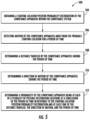
- FIG. 5 shows a flow chart of a method 500 of monitoring a conveyance apparatus within a conveyance system, in accordance with an embodiment of the disclosure.
- the conveyance system is an elevator system 101 and the conveyance apparatus is an elevator car 103 .
- a starting location position probability distribution of the conveyance apparatus within the conveyance system is obtained.
- the starting location position probability distribution will depict the probability that each landing 125 of an elevator system 101 may be the probable starting location.
- motion of the conveyance apparatus away from the probable starting location for a period of time is detected.
- a distance traveled by the conveyance apparatus during the period of time is determined.
- the distance traveled by the conveyance apparatus during the period of time may be determined by: detecting an acceleration of the conveyance apparatus during the period of time and determining the distance travelled by the conveyance apparatus in response to the acceleration and the period of time.
- the distance traveled by the conveyance apparatus during the period of time may be determined by: detecting a first air pressure at the probable starting location of the conveyance apparatus; detecting a second air pressure at the conclusion of the period of time; and determining the distance travelled by the conveyance apparatus in response to the first air pressure and the second air pressure.
- the distance traveled by the conveyance apparatus during the period of time may be determined by: obtaining a velocity of the conveyance apparatus during the period of time; and determining the distance travelled by the conveyance apparatus in response to the velocity of the conveyance apparatus and the period of time.
- the velocity may be a standard operating velocity of the conveyance apparatus or a detected velocity.
- the sensing apparatus 210 may utilize a look up table for a distance travelled over the time period based upon the standard operating velocity of the conveyance apparatus or the detected velocity of the conveyance apparatus.
- a direction of motion of the conveyance apparatus during the period of time is determined.
- the direction of motion of the conveyance apparatus may be determined in response to the acceleration of the conveyance apparatus detected during the period of time.
- the direction of motion of the conveyance apparatus may be determined in response to the first air pressure and the second air pressure.
- a probability of the conveyance apparatus being at each of a plurality of possible destination locations at a conclusion of the period of time is determined in response to the starting location position probability distribution and at least one of the distance traveled, the direction of motion, and the period of time.
- a probable destination location may be determined amongst the plurality of possible destination location.
- the probable destination location may be a possible destination location of the plurality of possible destination locations having the probability that is highest amongst the plurality of possible destination locations.
- the probability of the bottom two landings being a probable destination location is low to zero, because the conveyance system cannot move up two landings to the bottom two vertical landings. Further, the probable starting location then may adjust the probability that one of the remaining three top landing is the probable destination.
- the probabilities determined may be a weighted probability based on distance traveled. In another example, if hoistway is tall (e.g., landings 125 are spaced four meters apart) and a current location of the elevator car 103 is unknown then all floors may have same probability of being the probable starting location of the elevator car 103 . If the elevator car 103 travels up about twenty meters then it may be determined that the top four landings 125 are less likely to be the start position as the elevator car 103 most likely not move upward 20 meters from any of the top four landings 125 if the landings 125 are spaced four meters apart. Therefore, the probability is lowest for top landing 125 and then the probability increases for the next three landings 125 moving away from the top landing 125 .
- An alert may be activated when the probability of the conveyance apparatus being at each of a plurality of possible destination locations at a conclusion of the period of time is less than a selected probability. If the probability of the conveyance apparatus being at each of a plurality of possible destination locations at a conclusion of the period of time is less than a selected probability then it may be understood that the sensing apparatus 210 is uncertain of a location of the conveyance apparatus.
- the alert may be an audible, visual, and/or vibratory alert on a computing device (e.g., remote device 280 ) to alert the user of the computing device that the sensing apparatus 210 is uncertain of a location of the conveyance apparatus.
- the sensing apparatus 210 may perform a learning run and a learning mode.
- the sensing apparatus 210 is configured to define a floor map using just a sensing apparatus 210 .
- the floor map may be utilized later by the sensing apparatus to apply probabilities.
- the sensing apparatus 210 is learning the floor map of the elevator shaft 117 and assuming that the sensing apparatus 210 is constantly lost.
- learning mode or learning run may start from a smallest determined elevator system (e.g., 2 stops). If the elevator car 103 moves upward it may be determined that the probability of a bottom landing 125 being the possible destination location is now about 0% and the probability of an upper landing 125 being the possible destination location is about 100%.
- elevator car 103 moves further up to stop at a second landing then it may be determined that at least three landings 125 exist along the elevator shaft 114 . If the elevator car 125 then moves down to a third landing 125 but not as far as to reach the second landing 125 then it may be determined that there is a landing between the second landing and the third landing 125 and there are at least four landings 125 .
- a new landing 125 may only be added if the new measured location is more than a selected distance away from a previously detected landing 125 , which is to avoid detecting the same landing 125 and misinterpreting it as two different landings 125 .
- the learning mode or learning run may continue until all the floors have been reached.
- the learning mode or learning run may end when each detected landing 125 has been visited twice or a specific motion of the elevator car 103 was detected (e.g., ex. one landing 125 up, two landings 125 down, one landing 125 up). Once the learning mode or learning run is completed then the probable starting location may be given a 100% probability.
Abstract
Description
Claims (20)
Priority Applications (3)
| Application Number | Priority Date | Filing Date | Title |
|---|---|---|---|
| US16/266,297 US11649136B2 (en) | 2019-02-04 | 2019-02-04 | Conveyance apparatus location determination using probability |
| EP19214935.9A EP3693311A1 (en) | 2019-02-04 | 2019-12-10 | Conveyance apparatus location determination using probability |
| CN201911410279.XA CN111517187B (en) | 2019-02-04 | 2019-12-31 | Conveyor location determination using probabilities |
Applications Claiming Priority (1)
| Application Number | Priority Date | Filing Date | Title |
|---|---|---|---|
| US16/266,297 US11649136B2 (en) | 2019-02-04 | 2019-02-04 | Conveyance apparatus location determination using probability |
Publications (2)
| Publication Number | Publication Date |
|---|---|
| US20200247643A1 US20200247643A1 (en) | 2020-08-06 |
| US11649136B2 true US11649136B2 (en) | 2023-05-16 |
Family
ID=68848109
Family Applications (1)
| Application Number | Title | Priority Date | Filing Date |
|---|---|---|---|
| US16/266,297 Active 2042-03-18 US11649136B2 (en) | 2019-02-04 | 2019-02-04 | Conveyance apparatus location determination using probability |
Country Status (3)
| Country | Link |
|---|---|
| US (1) | US11649136B2 (en) |
| EP (1) | EP3693311A1 (en) |
| CN (1) | CN111517187B (en) |
Families Citing this family (4)
| Publication number | Priority date | Publication date | Assignee | Title |
|---|---|---|---|---|
| US11649136B2 (en) * | 2019-02-04 | 2023-05-16 | Otis Elevator Company | Conveyance apparatus location determination using probability |
| US11542124B2 (en) * | 2019-05-13 | 2023-01-03 | Otis Elevator Company | Sensor fusion door status detection |
| US20210094794A1 (en) * | 2019-09-27 | 2021-04-01 | Otis Elevator Company | Air pressure and acceleration sensor floor correction by elevator status information |
| EP3984936A1 (en) * | 2020-10-14 | 2022-04-20 | Otis Elevator Company | Monitoring system for conveyance system |
Citations (37)
| Publication number | Priority date | Publication date | Assignee | Title |
|---|---|---|---|---|
| US4493399A (en) | 1982-05-11 | 1985-01-15 | Mitsubishi Denki Kabushiki Kaisha | Elevator control system |
| US4700810A (en) | 1985-09-24 | 1987-10-20 | Kone Elevator Gmbh | Method of controlling an elevator |
| US4940117A (en) | 1988-02-16 | 1990-07-10 | Kone Elevator Gmbh | Procedure for the tuning of the position controller of an elevator |
| DE19911402A1 (en) | 1999-03-15 | 2000-09-21 | Otis Elevator Co | Control system for absolute positioning of elevator cabin controls cabin motion during normal operation with access to position reference values stored during learning pass along shaft |
| JP2004155554A (en) | 2002-11-07 | 2004-06-03 | Hitachi Ltd | Group management controller for elevator and method |
| CN101356108A (en) * | 2006-01-12 | 2009-01-28 | 奥蒂斯电梯公司 | Video auxiliary system for elevator control |
| US7484598B2 (en) * | 2005-08-19 | 2009-02-03 | Kone Corporation | Positioning method in an elevator system |
| US7699143B2 (en) | 2006-04-20 | 2010-04-20 | Inventio Ag | Method of setting the floor associations of a plurality of operating units of an elevator installation |
| EP2489621A1 (en) | 2011-02-17 | 2012-08-22 | SafeLine Europe | A method for determining and displaying a floor level indication. |
| US8540057B2 (en) | 2008-03-06 | 2013-09-24 | Inventio Ag | Generating elevator installation maintenance information |
| US8678143B2 (en) | 2008-06-13 | 2014-03-25 | Inventio Ag | Elevator installation maintenance monitoring utilizing a door acceleration sensor |
| CN104030121A (en) | 2014-07-01 | 2014-09-10 | 范奉和 | Elevator safe operation data coupling device and operating method |
| US8863908B2 (en) | 2010-09-09 | 2014-10-21 | Inventio Ag | Controlling a drive motor of an elevator installation |
| CN203976158U (en) | 2014-07-01 | 2014-12-03 | 范奉和 | A kind of elevator safety operation data coupling device |
| US9033114B2 (en) * | 2010-12-23 | 2015-05-19 | Inventio Ag | Determining elevator car position |
| CN104743418A (en) | 2015-03-19 | 2015-07-01 | 深圳市海浦蒙特科技有限公司 | Method for achieving self-learning leveling function of lifter used for building construction and position correction method |
| CN104828661A (en) | 2015-04-21 | 2015-08-12 | 深圳市海浦蒙特科技有限公司 | Elevator control method and system based on identification of position of lower force switch |
| CN104936879A (en) | 2013-01-23 | 2015-09-23 | 三菱电机株式会社 | Elevator device |
| CN105668360A (en) | 2016-03-18 | 2016-06-15 | 深圳市海浦蒙特科技有限公司 | Automatic elevator parameter learning method |
| US20160272460A1 (en) | 2013-10-28 | 2016-09-22 | Otis Elevator Company | Altitude-sensitive destination entry |
| EP3081519A1 (en) | 2015-04-16 | 2016-10-19 | Kone Corporation | Method for the position detection of an elevator car |
| CN205709297U (en) | 2016-06-27 | 2016-11-23 | 爱默生电梯有限公司 | A kind of emergency staircase |
| CN106144862A (en) * | 2015-04-03 | 2016-11-23 | 奥的斯电梯公司 | Passenger based on depth transducer for passenger traffic gate control senses |
| CN106395520A (en) * | 2015-07-31 | 2017-02-15 | 株式会社日立制作所 | Elevator group management system and elevator group management method |
| CN106516922A (en) | 2016-05-04 | 2017-03-22 | 谢杰清 | Operating behavior recording system of intelligent elevator |
| US20170253461A1 (en) * | 2014-08-29 | 2017-09-07 | Inventio Ag | Method and arrangement for determining elevator data based on the position of an elevator car |
| US20170349399A1 (en) | 2014-12-02 | 2017-12-07 | Inventio Ag | Method and apparatus for determining the position of an elevator car |
| US20170355555A1 (en) | 2016-06-13 | 2017-12-14 | Otis Elevator Company | Sensor and drive motor learn run for elevator systems |
| CN206842767U (en) | 2017-06-20 | 2018-01-05 | 淮安信息职业技术学院 | A kind of self study double mode elevator car position supervising device |
| US9950899B2 (en) | 2012-06-27 | 2018-04-24 | Kone Corporation | Position and load measurement system for an elevator including at least one sensor in the elevator car |
| DE102016123410A1 (en) | 2016-12-05 | 2018-06-07 | ITC Engineering GmbH & Co. KG | Position recognition of a driver's cabin in an elevator shaft via pattern comparison of profile data |
| CN108249239A (en) | 2017-12-25 | 2018-07-06 | 亚洲富士电梯股份有限公司 | Elevator control method and system |
| US20180265328A1 (en) | 2015-09-28 | 2018-09-20 | Inventio Ag | Elevator arrangement adapted for sound-based determining of positions of fixtures at various floors |
| WO2018177829A1 (en) | 2017-03-29 | 2018-10-04 | Thyssenkrupp Elevator Ag | Multi-cage lift installation and method for operating a multi-cage lift installation |
| CN109110598A (en) | 2017-06-26 | 2019-01-01 | 上海三菱电梯有限公司 | elevator floor position learning system |
| US20200247643A1 (en) * | 2019-02-04 | 2020-08-06 | Otis Elevator Company | Conveyance apparatus location determination using probability |
| US20200262678A1 (en) * | 2017-11-07 | 2020-08-20 | Thyssenkrupp Elevator Innovation And Operations Ag | Passenger conveying system comprising monitoring device |
Family Cites Families (4)
| Publication number | Priority date | Publication date | Assignee | Title |
|---|---|---|---|---|
| JP2001335244A (en) * | 2000-05-29 | 2001-12-04 | Mitsubishi Electric Corp | Elevator system, and control method thereof |
| JP2012111611A (en) * | 2010-11-26 | 2012-06-14 | Toshiba Elevator Co Ltd | Elevator |
| US9834405B2 (en) * | 2014-11-10 | 2017-12-05 | Mitsubishi Electric Research Laboratories, Inc. | Method and system for scheduling elevator cars in a group elevator system with uncertain information about arrivals of future passengers |
| CN107416623A (en) * | 2017-06-29 | 2017-12-01 | 深圳市泰衡诺科技有限公司上海分公司 | A kind of floor detection prompt system and method |
-
2019
- 2019-02-04 US US16/266,297 patent/US11649136B2/en active Active
- 2019-12-10 EP EP19214935.9A patent/EP3693311A1/en active Pending
- 2019-12-31 CN CN201911410279.XA patent/CN111517187B/en active Active
Patent Citations (38)
| Publication number | Priority date | Publication date | Assignee | Title |
|---|---|---|---|---|
| US4493399A (en) | 1982-05-11 | 1985-01-15 | Mitsubishi Denki Kabushiki Kaisha | Elevator control system |
| US4700810A (en) | 1985-09-24 | 1987-10-20 | Kone Elevator Gmbh | Method of controlling an elevator |
| US4940117A (en) | 1988-02-16 | 1990-07-10 | Kone Elevator Gmbh | Procedure for the tuning of the position controller of an elevator |
| DE19911402A1 (en) | 1999-03-15 | 2000-09-21 | Otis Elevator Co | Control system for absolute positioning of elevator cabin controls cabin motion during normal operation with access to position reference values stored during learning pass along shaft |
| JP2004155554A (en) | 2002-11-07 | 2004-06-03 | Hitachi Ltd | Group management controller for elevator and method |
| US7484598B2 (en) * | 2005-08-19 | 2009-02-03 | Kone Corporation | Positioning method in an elevator system |
| CN101356108A (en) * | 2006-01-12 | 2009-01-28 | 奥蒂斯电梯公司 | Video auxiliary system for elevator control |
| US7699143B2 (en) | 2006-04-20 | 2010-04-20 | Inventio Ag | Method of setting the floor associations of a plurality of operating units of an elevator installation |
| US8540057B2 (en) | 2008-03-06 | 2013-09-24 | Inventio Ag | Generating elevator installation maintenance information |
| US8678143B2 (en) | 2008-06-13 | 2014-03-25 | Inventio Ag | Elevator installation maintenance monitoring utilizing a door acceleration sensor |
| US8863908B2 (en) | 2010-09-09 | 2014-10-21 | Inventio Ag | Controlling a drive motor of an elevator installation |
| US9033114B2 (en) * | 2010-12-23 | 2015-05-19 | Inventio Ag | Determining elevator car position |
| EP2489621A1 (en) | 2011-02-17 | 2012-08-22 | SafeLine Europe | A method for determining and displaying a floor level indication. |
| US9950899B2 (en) | 2012-06-27 | 2018-04-24 | Kone Corporation | Position and load measurement system for an elevator including at least one sensor in the elevator car |
| CN104936879A (en) | 2013-01-23 | 2015-09-23 | 三菱电机株式会社 | Elevator device |
| US20160272460A1 (en) | 2013-10-28 | 2016-09-22 | Otis Elevator Company | Altitude-sensitive destination entry |
| CN104030121A (en) | 2014-07-01 | 2014-09-10 | 范奉和 | Elevator safe operation data coupling device and operating method |
| CN203976158U (en) | 2014-07-01 | 2014-12-03 | 范奉和 | A kind of elevator safety operation data coupling device |
| US20170253461A1 (en) * | 2014-08-29 | 2017-09-07 | Inventio Ag | Method and arrangement for determining elevator data based on the position of an elevator car |
| US20170349399A1 (en) | 2014-12-02 | 2017-12-07 | Inventio Ag | Method and apparatus for determining the position of an elevator car |
| CN104743418A (en) | 2015-03-19 | 2015-07-01 | 深圳市海浦蒙特科技有限公司 | Method for achieving self-learning leveling function of lifter used for building construction and position correction method |
| CN106144862A (en) * | 2015-04-03 | 2016-11-23 | 奥的斯电梯公司 | Passenger based on depth transducer for passenger traffic gate control senses |
| US20160304313A1 (en) * | 2015-04-16 | 2016-10-20 | Kone Corporation | Method for the position detection of an elevator car |
| EP3081519A1 (en) | 2015-04-16 | 2016-10-19 | Kone Corporation | Method for the position detection of an elevator car |
| CN104828661A (en) | 2015-04-21 | 2015-08-12 | 深圳市海浦蒙特科技有限公司 | Elevator control method and system based on identification of position of lower force switch |
| CN106395520A (en) * | 2015-07-31 | 2017-02-15 | 株式会社日立制作所 | Elevator group management system and elevator group management method |
| US20180265328A1 (en) | 2015-09-28 | 2018-09-20 | Inventio Ag | Elevator arrangement adapted for sound-based determining of positions of fixtures at various floors |
| CN105668360A (en) | 2016-03-18 | 2016-06-15 | 深圳市海浦蒙特科技有限公司 | Automatic elevator parameter learning method |
| CN106516922A (en) | 2016-05-04 | 2017-03-22 | 谢杰清 | Operating behavior recording system of intelligent elevator |
| US20170355555A1 (en) | 2016-06-13 | 2017-12-14 | Otis Elevator Company | Sensor and drive motor learn run for elevator systems |
| CN205709297U (en) | 2016-06-27 | 2016-11-23 | 爱默生电梯有限公司 | A kind of emergency staircase |
| DE102016123410A1 (en) | 2016-12-05 | 2018-06-07 | ITC Engineering GmbH & Co. KG | Position recognition of a driver's cabin in an elevator shaft via pattern comparison of profile data |
| WO2018177829A1 (en) | 2017-03-29 | 2018-10-04 | Thyssenkrupp Elevator Ag | Multi-cage lift installation and method for operating a multi-cage lift installation |
| CN206842767U (en) | 2017-06-20 | 2018-01-05 | 淮安信息职业技术学院 | A kind of self study double mode elevator car position supervising device |
| CN109110598A (en) | 2017-06-26 | 2019-01-01 | 上海三菱电梯有限公司 | elevator floor position learning system |
| US20200262678A1 (en) * | 2017-11-07 | 2020-08-20 | Thyssenkrupp Elevator Innovation And Operations Ag | Passenger conveying system comprising monitoring device |
| CN108249239A (en) | 2017-12-25 | 2018-07-06 | 亚洲富士电梯股份有限公司 | Elevator control method and system |
| US20200247643A1 (en) * | 2019-02-04 | 2020-08-06 | Otis Elevator Company | Conveyance apparatus location determination using probability |
Non-Patent Citations (4)
| Title |
|---|
| Chinese Office Action for Application No. 201911410279.X; dated Aug. 3, 2022; 10 Pages. |
| Chinese Office Action for Application No. 201911410279.X; dated Nov. 26, 2021; 9 Pages. |
| European Search Report for Application No. 19214935.9; dated Jul. 10, 2020; 5 Pages. |
| The Extended European Search Report for Application No. 19214935.9-1017; Report dated Jun. 19, 2020; Report Received Date: Oct. 7, 2020; 5 pages. |
Also Published As
| Publication number | Publication date |
|---|---|
| EP3693311A1 (en) | 2020-08-12 |
| CN111517187B (en) | 2023-04-28 |
| CN111517187A (en) | 2020-08-11 |
| US20200247643A1 (en) | 2020-08-06 |
Similar Documents
| Publication | Publication Date | Title |
|---|---|---|
| US10822199B2 (en) | Sensor fusion of acceleration sensor and air pressure sensor information to estimate elevator floor level and position | |
| US11649136B2 (en) | Conveyance apparatus location determination using probability | |
| US20200361745A1 (en) | Elevator health status ranking out of acceleration maximum values | |
| US11472666B2 (en) | Elevator maintenance app matching mechanics position with faults detected | |
| EP3778462B1 (en) | Elevator shaft distributed health level with mechanic feedback condition based monitoring | |
| US20190367325A1 (en) | Wireless sensor for conveyance system monitoring | |
| EP3798170A1 (en) | Air pressure and acceleration sensor floor correction by elevator status information | |
| EP3771680B1 (en) | Pressure sensor algorithm to detect elevator status information | |
| EP3733583B1 (en) | Elevator shaft distributed health level | |
| US11535491B2 (en) | Verification of trapped passenger alarm | |
| EP3733581A1 (en) | Air pressure sensor algorithm to detect elevator direction of motion | |
| US11542124B2 (en) | Sensor fusion door status detection | |
| EP3670415A2 (en) | Virtual sensor for elevator monitoring | |
| US11718500B2 (en) | Customer behavior driven predictive maintenance | |
| US20220106158A1 (en) | Floor identification using magnetic signature referencing and sensor fusion | |
| US11958722B2 (en) | Virtual sensor for elevator monitoring | |
| US20220112050A1 (en) | Elevator system floor height mapping |
Legal Events
| Date | Code | Title | Description |
|---|---|---|---|
| FEPP | Fee payment procedure |
Free format text: ENTITY STATUS SET TO UNDISCOUNTED (ORIGINAL EVENT CODE: BIG.); ENTITY STATUS OF PATENT OWNER: LARGE ENTITY |
|
| AS | Assignment |
Owner name: OTIS ELEVATOR COMPANY, CONNECTICUT Free format text: ASSIGNMENT OF ASSIGNORS INTEREST;ASSIGNORS:WITCZAK, TADEUSZ PAWEL;TRCKA, NIKOLA;WOS, LINDSAY;REEL/FRAME:048235/0625 Effective date: 20190131 Owner name: APOLLOGIC SP. Z O.O., POLAND Free format text: ASSIGNMENT OF ASSIGNORS INTEREST;ASSIGNORS:SHVETS, OLEH;BOHONOS, ANDRZEJ;MAJCHRZAK, LUKASZ;AND OTHERS;SIGNING DATES FROM 20190201 TO 20190204;REEL/FRAME:048241/0080 |
|
| AS | Assignment |
Owner name: APOLLOGIC SP. Z O.O., POLAND Free format text: CORRECTIVE ASSIGNMENT TO CORRECT THE ASSIGNEE ADDRESS PREVIOUSLY RECORDED AT REEL: 048241 FRAME: 0080. ASSIGNOR(S) HEREBY CONFIRMS THE ASSIGNMENT;ASSIGNORS:SHVETS, OLEH;BOHONOS, ANDRZEJ;MAJCHRZAK, LUKASZ;AND OTHERS;SIGNING DATES FROM 20190201 TO 20190204;REEL/FRAME:048964/0431 |
|
| STPP | Information on status: patent application and granting procedure in general |
Free format text: NON FINAL ACTION MAILED |
|
| AS | Assignment |
Owner name: OTIS ELEVATOR COMPANY, CONNECTICUT Free format text: ASSIGNMENT OF ASSIGNORS INTEREST;ASSIGNOR:APOLLOGIC SP. Z O.O.;REEL/FRAME:061959/0214 Effective date: 20180607 |
|
| STPP | Information on status: patent application and granting procedure in general |
Free format text: RESPONSE TO NON-FINAL OFFICE ACTION ENTERED AND FORWARDED TO EXAMINER |
|
| STCF | Information on status: patent grant |
Free format text: PATENTED CASE |