EP3771680B1 - Pressure sensor algorithm to detect elevator status information - Google Patents
Pressure sensor algorithm to detect elevator status information Download PDFInfo
- Publication number
- EP3771680B1 EP3771680B1 EP20174902.5A EP20174902A EP3771680B1 EP 3771680 B1 EP3771680 B1 EP 3771680B1 EP 20174902 A EP20174902 A EP 20174902A EP 3771680 B1 EP3771680 B1 EP 3771680B1
- Authority
- EP
- European Patent Office
- Prior art keywords
- time
- change
- conveyance apparatus
- rate
- air pressure
- Prior art date
- Legal status (The legal status is an assumption and is not a legal conclusion. Google has not performed a legal analysis and makes no representation as to the accuracy of the status listed.)
- Active
Links
- 230000003068 static effect Effects 0.000 claims description 111
- 230000004044 response Effects 0.000 claims description 88
- 230000001133 acceleration Effects 0.000 claims description 37
- 238000000034 method Methods 0.000 claims description 32
- 230000033001 locomotion Effects 0.000 claims description 25
- 238000001514 detection method Methods 0.000 claims description 16
- 238000012544 monitoring process Methods 0.000 claims description 8
- 238000004891 communication Methods 0.000 description 14
- 238000012545 processing Methods 0.000 description 10
- 230000001413 cellular effect Effects 0.000 description 6
- QVFWZNCVPCJQOP-UHFFFAOYSA-N chloralodol Chemical compound CC(O)(C)CC(C)OC(O)C(Cl)(Cl)Cl QVFWZNCVPCJQOP-UHFFFAOYSA-N 0.000 description 3
- 238000010586 diagram Methods 0.000 description 3
- 230000007246 mechanism Effects 0.000 description 3
- 229910000831 Steel Inorganic materials 0.000 description 2
- 230000036461 convulsion Effects 0.000 description 2
- 238000004146 energy storage Methods 0.000 description 2
- 238000009434 installation Methods 0.000 description 2
- 238000005259 measurement Methods 0.000 description 2
- 230000003287 optical effect Effects 0.000 description 2
- 238000003672 processing method Methods 0.000 description 2
- 239000010959 steel Substances 0.000 description 2
- 238000013459 approach Methods 0.000 description 1
- 238000013473 artificial intelligence Methods 0.000 description 1
- 238000004364 calculation method Methods 0.000 description 1
- 239000003990 capacitor Substances 0.000 description 1
- 230000000694 effects Effects 0.000 description 1
- 230000005611 electricity Effects 0.000 description 1
- 230000005484 gravity Effects 0.000 description 1
- 238000003306 harvesting Methods 0.000 description 1
- 230000006698 induction Effects 0.000 description 1
- 230000000977 initiatory effect Effects 0.000 description 1
- 238000004519 manufacturing process Methods 0.000 description 1
- 238000007781 pre-processing Methods 0.000 description 1
- 238000003860 storage Methods 0.000 description 1
- 230000001360 synchronised effect Effects 0.000 description 1
- 230000003442 weekly effect Effects 0.000 description 1
Images


Classifications
-
- B—PERFORMING OPERATIONS; TRANSPORTING
- B66—HOISTING; LIFTING; HAULING
- B66B—ELEVATORS; ESCALATORS OR MOVING WALKWAYS
- B66B1/00—Control systems of elevators in general
- B66B1/34—Details, e.g. call counting devices, data transmission from car to control system, devices giving information to the control system
- B66B1/3492—Position or motion detectors or driving means for the detector
-
- B—PERFORMING OPERATIONS; TRANSPORTING
- B66—HOISTING; LIFTING; HAULING
- B66B—ELEVATORS; ESCALATORS OR MOVING WALKWAYS
- B66B5/00—Applications of checking, fault-correcting, or safety devices in elevators
- B66B5/0006—Monitoring devices or performance analysers
- B66B5/0018—Devices monitoring the operating condition of the elevator system
-
- B—PERFORMING OPERATIONS; TRANSPORTING
- B66—HOISTING; LIFTING; HAULING
- B66B—ELEVATORS; ESCALATORS OR MOVING WALKWAYS
- B66B27/00—Indicating operating conditions of escalators or moving walkways
-
- B—PERFORMING OPERATIONS; TRANSPORTING
- B66—HOISTING; LIFTING; HAULING
- B66B—ELEVATORS; ESCALATORS OR MOVING WALKWAYS
- B66B5/00—Applications of checking, fault-correcting, or safety devices in elevators
- B66B5/0006—Monitoring devices or performance analysers
- B66B5/0018—Devices monitoring the operating condition of the elevator system
- B66B5/0031—Devices monitoring the operating condition of the elevator system for safety reasons
-
- B—PERFORMING OPERATIONS; TRANSPORTING
- B66—HOISTING; LIFTING; HAULING
- B66B—ELEVATORS; ESCALATORS OR MOVING WALKWAYS
- B66B5/00—Applications of checking, fault-correcting, or safety devices in elevators
- B66B5/02—Applications of checking, fault-correcting, or safety devices in elevators responsive to abnormal operating conditions
- B66B5/04—Applications of checking, fault-correcting, or safety devices in elevators responsive to abnormal operating conditions for detecting excessive speed
-
- G—PHYSICS
- G01—MEASURING; TESTING
- G01C—MEASURING DISTANCES, LEVELS OR BEARINGS; SURVEYING; NAVIGATION; GYROSCOPIC INSTRUMENTS; PHOTOGRAMMETRY OR VIDEOGRAMMETRY
- G01C5/00—Measuring height; Measuring distances transverse to line of sight; Levelling between separated points; Surveyors' levels
- G01C5/06—Measuring height; Measuring distances transverse to line of sight; Levelling between separated points; Surveyors' levels by using barometric means
-
- G—PHYSICS
- G01—MEASURING; TESTING
- G01D—MEASURING NOT SPECIALLY ADAPTED FOR A SPECIFIC VARIABLE; ARRANGEMENTS FOR MEASURING TWO OR MORE VARIABLES NOT COVERED IN A SINGLE OTHER SUBCLASS; TARIFF METERING APPARATUS; MEASURING OR TESTING NOT OTHERWISE PROVIDED FOR
- G01D21/00—Measuring or testing not otherwise provided for
- G01D21/02—Measuring two or more variables by means not covered by a single other subclass
Definitions
- the embodiments herein relate to the field of conveyance systems, and specifically to a method and apparatus for monitoring a position of a conveyance apparatus of a conveyance system.
- a precise position of a conveyance apparatus within a conveyance systems may be difficult and/or costly to determine.
- WO 2011/032660 discloses a consumer control device and a method for actuating at least one consumer of an elevator.
- US 8 327 553 B2 discloses a device and a method for determining the vertical spacing of objects while carrying out positioning tasks with a vertical travel portion.
- a method of monitoring motion of a conveyance apparatus within a conveyance system as claimed in claim 1 is provided.
- Further embodiments may include: detecting a first static atmospheric air pressure proximate the conveyance apparatus at about the first time using a static pressure sensor located off of the conveyance apparatus; detecting a second static atmospheric air pressure proximate the conveyance apparatus at about the second time using the static pressure sensor located off of the conveyance apparatus; determining the rate of change in static atmospheric air pressure proximate the conveyance apparatus between the first time and the second time in response to the first static atmospheric air pressure, the second static atmospheric air pressure, the first time, and the second time; determining that the rate of change in static atmospheric air pressure is above a threshold static atmospheric air pressure rate of change; determining that the conveyance apparatus has not moved between the first time and the second time in response to determining that the rate of change in atmospheric air pressure is above the threshold atmospheric air pressure rate of change; and disconfirming the height change in response to determining that the conveyance apparatus has not moved between the first time and the second time.
- Further embodiments may include: detecting a first static atmospheric air pressure proximate the conveyance apparatus at about the first time using a static pressure sensor located off of the conveyance apparatus; detecting a second static atmospheric air pressure proximate the conveyance apparatus at about the second time using the static pressure sensor located off of the conveyance apparatus; determining the rate of change in static atmospheric air pressure proximate the conveyance apparatus between the first time and the second time in response to the first static atmospheric air pressure, the second static atmospheric air pressure, the first time, and the second time; and adjusting the height change in response to the rate of change in static atmospheric air pressure.
- Further embodiments may include: detecting a first temperature proximate the conveyance apparatus at about the first time; detecting a second temperature proximate the conveyance apparatus at about the second time; determining the rate of change in temperature proximate the conveyance apparatus between the first time and the second time in response to the first temperature, the second temperature, the first time, and the second time; determining that the rate of change in temperature is above a threshold temperature rate of change; determining that the conveyance apparatus has not moved between the first time and the second time in response to determining that the rate of change in temperature is above the threshold temperature rate of change; and disconfirming the height change in response to determining that the conveyance apparatus has not moved between the first time and the second time.
- Further embodiments may include: detecting a first temperature proximate the conveyance apparatus at about the first time; detecting a second temperature proximate the conveyance apparatus at about the second time; determining the rate of change in temperature proximate the conveyance apparatus between the first time and the second time in response to the first temperature, the second temperature, the first time, and the second time; determining that the rate of change in temperature is below a threshold temperature rate of change; determining that the conveyance apparatus has moved between the first time and the second time in response to determining that the rate of change in temperature is below the threshold temperature rate of change; and confirming the height change in response to determining that the conveyance apparatus has moved between the first time and the second time.
- Further embodiments may include: detecting a first relative humidity proximate the conveyance apparatus at about the first time; detecting a second relative humidity proximate the conveyance apparatus at about the second time; determining the rate of change in relative humidity proximate the conveyance apparatus between the first time and the second time in response to the first relative humidity, the second relative humidity, the first time, and the second time; determining that the rate of change in relative humidity is above a threshold relative humidity rate of change; determining that the conveyance apparatus has not moved between the first time and the second time in response to determining that the rate of change in relative humidity is above the threshold relative humidity rate of change; and disconfirming the height change in response to determining that the conveyance apparatus has not moved between the first time and the second time.
- conveyance system is an elevator system and the conveyance apparatus is an elevator car.
- a sensing apparatus for monitoring a conveyance apparatus within a conveyance system as claimed in claim 10 is provided.
- the operations further include: detecting a first static atmospheric air pressure proximate the conveyance apparatus at about the first time using a static pressure sensor located off of the conveyance apparatus; detecting a second static atmospheric air pressure proximate the conveyance apparatus at about the second time using the static pressure sensor located off of the conveyance apparatus; determining the rate of change in static atmospheric air pressure proximate the conveyance apparatus between the first time and the second time in response to the first static atmospheric air pressure, the second static atmospheric air pressure, the first time, and the second time; and adjusting the height change in response to the rate of change in static atmospheric air pressure.
- the operations further include: detecting a first temperature proximate the conveyance apparatus at about the first time; detecting a second temperature proximate the conveyance apparatus at about the second time; determining the rate of change in temperature proximate the conveyance apparatus between the first time and the second time in response to the first temperature, the second temperature, the first time, and the second time; determining that the rate of change in temperature is above a threshold temperature rate of change; determining that the conveyance apparatus has not moved between the first time and the second time in response to determining that the rate of change in temperature is above the threshold temperature rate of change; and disconfirming the height change in response to determining that the conveyance apparatus has not moved between the first time and the second time.
- the operations further include: detecting a first temperature proximate the conveyance apparatus at about the first time; detecting a second temperature proximate the conveyance apparatus at about the second time; determining the rate of change in temperature proximate the conveyance apparatus between the first time and the second time in response to the first temperature, the second temperature, the first time, and the second time; determining that the rate of change in temperature is below a threshold temperature rate of change; determining that the conveyance apparatus has moved between the first time and the second time in response to determining that the rate of change in temperature is below the threshold temperature rate of change; and confirming the height change in response to determining that the conveyance apparatus has moved between the first time and the second time.
- the operations further include: detecting a first relative humidity proximate the conveyance apparatus at about the first time; detecting a second relative humidity proximate the conveyance apparatus at about the second time; determining the rate of change in relative humidity proximate the conveyance apparatus between the first time and the second time in response to the first relative humidity, the second relative humidity, the first time, and the second time; determining that the rate of change in relative humidity is above a threshold relative humidity rate of change; determining that the conveyance apparatus has not moved between the first time and the second time in response to determining that the rate of change in relative humidity is above the threshold relative humidity rate of change; and disconfirming the height change in response to determining that the conveyance apparatus has not moved between the first time and the second time.
- conveyance system is an elevator system and the conveyance apparatus is an elevator car.
- FIG. 1 is a perspective view of an elevator system 101 including an elevator car 103, a counterweight 105, a tension member 107, a guide rail 109, a machine 111, a position reference system 113, and a controller 115.
- the elevator car 103 and counterweight 105 are connected to each other by the tension member 107.
- the tension member 107 may include or be configured as, for example, ropes, steel cables, and/or coated-steel belts.
- the counterweight 105 is configured to balance a load of the elevator car 103 and is configured to facilitate movement of the elevator car 103 concurrently and in an opposite direction with respect to the counterweight 105 within an elevator shaft 117 and along the guide rail 109.
- the tension member 107 engages the machine 111, which is part of an overhead structure of the elevator system 101.
- the machine 111 is configured to control movement between the elevator car 103 and the counterweight 105.
- the position reference system 113 may be mounted on a fixed part at the top of the elevator shaft 117, such as on a support or guide rail, and may be configured to provide position signals related to a position of the elevator car 103 within the elevator shaft 117. In other embodiments, the position reference system 113 may be directly mounted to a moving component of the machine 111, or may be located in other positions and/or configurations as known in the art.
- the position reference system 113 can be any device or mechanism for monitoring a position of an elevator car and/or counter weight, as known in the art.
- the position reference system 113 can be an encoder, sensor, or other system and can include velocity sensing, absolute position sensing, etc., as will be appreciated by those of skill in the art.
- the controller 115 is located, as shown, in a controller room 121 of the elevator shaft 117 and is configured to control the operation of the elevator system 101, and particularly the elevator car 103.
- the controller 115 may provide drive signals to the machine 111 to control the acceleration, deceleration, leveling, stopping, etc. of the elevator car 103.
- the controller 115 may also be configured to receive position signals from the position reference system 113 or any other desired position reference device.
- the elevator car 103 may stop at one or more landings 125 as controlled by the controller 115.
- the controller 115 can be located and/or configured in other locations or positions within the elevator system 101. In one embodiment, the controller may be located remotely or in the cloud.
- the machine 111 may include a motor or similar driving mechanism.
- the machine 111 is configured to include an electrically driven motor.
- the power supply for the motor may be any power source, including a power grid, which, in combination with other components, is supplied to the motor.
- the machine 111 may include a traction sheave that imparts force to tension member 107 to move the elevator car 103 within elevator shaft 117.
- FIG. 1 is merely a non-limiting example presented for illustrative and explanatory purposes.
- the system comprises a conveyance system that moves passengers between floors and/or along a single floor.
- conveyance systems may include escalators, people movers, etc.
- embodiments described herein are not limited to elevator systems, such as that shown in Figure 1 .
- embodiments disclosed herein may be applicable conveyance systems such as an elevator system 101 and a conveyance apparatus of the conveyance system such as an elevator car 103 of the elevator system 101.
- embodiments disclosed herein may be applicable conveyance systems such as an escalator system and a conveyance apparatus of the conveyance system such as a moving stair of the escalator system.
- the sensing apparatus 210 is configured to detect sensor data 202 of the elevator car 103 and transmit the sensor data 202 to a remote device 280.
- Sensor data 202 may include but is not limited to pressure data 314, vibratory signatures (i.e., vibrations over a period of time) or accelerations 312 and derivatives or integrals of accelerations 312 of the elevator car 103, such as, for example, distance, velocity, jerk, jounce, snap... etc.
- Sensor data 202 may also include light, sound, humidity, and temperature, or any other desired data parameter.
- the pressure data 314 may include atmospheric air pressure within the elevator shaft 117. It should be appreciated that, although particular systems are separately defined in the schematic block diagrams, each or any of the systems may be otherwise combined or separated via hardware and/or software.
- the sensing apparatus 210 may be a single sensor or may be multiple separate sensors that are interconnected.
- the sensing apparatus 210 is configured to transmit sensor data 202 that is raw and unprocessed to the controller 115 of the elevator system 101 for processing. In another embodiment, the sensing apparatus 210 is configured to process the sensor data 202 prior to transmitting the sensor data 202 to the controller 115 through a processing method, such as, for example, edge processing. In another embodiment, the sensing apparatus 210 is configured to transmit sensor data 202 that is raw and unprocessed to a remote system 280 for processing. In yet another embodiment, the sensing apparatus 210 is configured to process the sensor data 202 prior to transmitting the sensor data 202 to the remote device 280 through a processing method, such as, for example, edge processing.
- the processing of the sensor data 202 may reveal data, such as, for example, a number of elevator door openings/closings, elevator door time, vibrations, vibratory signatures, a number of elevator rides, elevator ride performance, elevator flight time, probable car position (e.g. elevation, floor number), releveling events, rollbacks, elevator car 103 x, y acceleration at a position: (i.e., rail topology), elevator car 103 x, y vibration signatures at a position: (i.e., rail topology), door performance at a landing number, nudging event, vandalism events, emergency stops, etc.
- data such as, for example, a number of elevator door openings/closings, elevator door time, vibrations, vibratory signatures, a number of elevator rides, elevator ride performance, elevator flight time, probable car position (e.g. elevation, floor number), releveling events, rollbacks, elevator car 103 x, y acceleration at a position: (i.e., rail topology),
- the remote device 280 may be a computing device, such as, for example, a desktop, a cloud based computer, and/or a cloud based artificial intelligence (AI) computing system.
- the remote device 280 may also be a mobile computing device that is typically carried by a person, such as, for example a smartphone, PDA, smartwatch, tablet, laptop, etc.
- the remote device 280 may also be two separate devices that are synced together, such as, for example, a cellular phone and a desktop computer synced over an internet connection.
- the remote device 280 may be an electronic controller including a processor 282 and an associated memory 284 comprising computer-executable instructions that, when executed by the processor 282, cause the processor 282 to perform various operations.
- the processor 282 may be, but is not limited to, a single-processor or multi-processor system of any of a wide array of possible architectures, including field programmable gate array (FPGA), central processing unit (CPU), application specific integrated circuits (ASIC), digital signal processor (DSP) or graphics processing unit (GPU) hardware arranged homogenously or heterogeneously.
- the memory 284 may be but is not limited to a random access memory (RAM), read only memory (ROM), or other electronic, optical, magnetic or any other computer readable medium.
- the sensing apparatus 210 is configured to transmit the sensor data 202 to the controller 115 or the remote device 280 via short-range wireless protocols 203 and/or long-range wireless protocols 204.
- Short-range wireless protocols 203 may include but are not limited to Bluetooth, Wi-Fi, HaLow (801.11ah), zWave, ZigBee, or Wireless M-Bus.
- the sensing apparatus 210 is configured to transmit the sensor data 202 directly to the controller 115 or to a local gateway device 240 and the local gateway device 240 is configured to transmit the sensor data 202 to the remote device 280 through a network 250 or to the controller 115.
- the network 250 may be a computing network, such as, for example, a cloud computing network, cellular network, or any other computing network known to one of skill in the art.
- the sensing apparatus 210 is configured to transmit the sensor data 202 to the remote device 280 through a network 250.
- Long-range wireless protocols 204 may include but are not limited to cellular, satellite, LTE (NB-IoT, CAT M1), LoRa, Satellite, Ingenu, or SigFox.
- the sensing apparatus 210 may be configured to detect sensor data 202 including acceleration in any number of directions.
- the sensing apparatus may detect sensor data 202 including accelerations 312 along three axis, an X axis, a Y axis, and a Z axis, as show in in FIG. 2 .
- the X axis may be perpendicular to the doors 104 of the elevator car 103, as shown in FIG. 2 .
- the Y axis may be parallel to the doors 104 of the elevator car 103, as shown in FIG. 2 .
- the Z axis may be aligned vertically parallel with the elevator shaft 117 and pull of gravity, as shown in FIG. 2 .
- the acceleration data 312 may reveal vibratory signatures generated along the X-axis, the Y-axis, and the Z-axis.
- the sensor system 200 includes a static pressure sensor 228A configured to detect static pressure data 314A, which includes a static atmospheric air pressure.
- the static pressure sensor 228A is located at a static or stationary location off of the elevator car 103. Thereby, a change in static atmospheric air pressure may be solely caused by the weather and not by movement of the elevator car 103.
- the static pressure sensor 228A is configured to transmit the static pressure data 314A to the controller 115 or the remote device 280 via short-range wireless protocols 203 and/or long-range wireless protocols 204.
- Short-range wireless protocols 203 may include but are not limited to Bluetooth, Wi-Fi, HaLow (801.11ah), zWave, ZigBee, or Wireless M-Bus.
- the static pressure sensor 228A is configured to transmit the static pressure data 314A directly to the controller 115 or to a local gateway device 240 and the local gateway device 240 is configured to transmit the static pressure data 314A to the remote device 280 through a network 250 or to the controller 115.
- the network 250 may be a computing network, such as, for example, a cloud computing network, cellular network, or any other computing network known to one of skill in the art.
- the static pressure sensor 228A is configured to transmit the static pressure data 314A to the remote device 280 through a network 250.
- Long-range wireless protocols 204 may include but are not limited to cellular, satellite, LTE (NB-IoT, CAT M1), LoRa, Satellite, Ingenu, or SigFox.
- FIG. 3 shows a possible installation location of the sensing apparatus 210 within the elevator system 101.
- the sensing apparatus 210 may include a magnet (not show) to removably attach to the elevator car 103.
- the sensing apparatus 210 may be installed on the door hanger 104a and/or the door 104 of the elevator system 101. It is understood that the sensing apparatus 210 may also be installed in other locations other than the door hanger 104a and the door 104 of the elevator system 101. It is also understood that multiple sensing apparatus 210 are illustrated in FIG. 3 to show various locations of the sensing apparatus 210 and the embodiments disclosed herein may include one or more sensing apparatus 210.
- the sensing apparatus 210 may be attached to a door header 104e of a door 104 of the elevator car 103. In another embodiment, the sensing apparatus 210 may be located on a door header 104e proximate a top portion 104f of the elevator car 103. In another embodiment, the sensing apparatus 210 is installed elsewhere on the elevator car 103, such as, for example, directly on the door 104.
- the sensing apparatus 201 may be located on the elevator car 103 in the selected areas 106, as shown in FIG. 3 .
- the doors 104 are operably connected to the door header 104e through a door hanger 104a located proximate a top portion 104b of the door 104.
- the door hanger 104a includes guide wheels 104c that allow the door 104 to slide open and close along a guide rail 104d on the door header 104e.
- the door hanger 104a is an easy to access area to attach the sensing apparatus 210 because the door hanger 104a is accessible when the elevator car 103 is at landing 125 and the elevator door 104 is open.
- the door hanger 104a also provides ample clearance for the sensing apparatus 210 during operation of the elevator car 103, such as, for example, door 104 opening and closing. Due to the mounting location of the sensing apparatus 210 on the door hanger 104a, the sensing apparatus 210 may detect open and close motions (i.e., acceleration) of the door 104 of the elevator car 103 and a door at the landing 125. Additionally mounting the sensing apparatus 210 on the hanger 104a allows for recording of a ride quality of the elevator car 103.
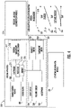
- FIG. 4 illustrates a block diagram of the sensing apparatus 210 of the sensing system of FIGs. 2 and 3 . It should be appreciated that, although particular systems are separately defined in the schematic block diagram of FIG. 4 , each or any of the systems may be otherwise combined or separated via hardware and/or software. As shown in FIG. 4 , the sensing apparatus 210 may include a controller 212, a plurality of sensors 217 in communication with the controller 212, a communication module 220 in communication with the controller 212, and a power source 222 electrically connected to the controller 212.
- the plurality of sensors 217 includes an inertial measurement unit (IMU) sensor 218 configured to detect sensor data 202 including accelerations 312 of the sensing apparatus 210 and the elevator car 103 when the sensing apparatus 210 is attached to the elevator car 103.
- the IMU sensor 218 may be a sensor, such as, for example, an accelerometer, a gyroscope, or a similar sensor known to one of skill in the art.
- the accelerations 312 detected by the IMU sensor 218 may include accelerations 312 as well as derivatives or integrals of accelerations, such as, for example, velocity, jerk, jounce, snap... etc.
- the IMU sensor 218 is in communication with the controller 212 of the sensing apparatus 210.
- the plurality of sensors 217 includes a pressure sensor 228 is configured to detect sensor data 202 including pressure data 314, such as, for example, atmospheric air pressure within the elevator shaft 117.
- the pressure sensor 228 may be a pressure altimeter or barometric altimeter in two non-limiting examples.
- the pressure sensor 228 is in communication with the controller 212.
- the controller 212 of the sensing apparatus 210 includes a processor 214 and an associated memory 216 comprising computer-executable instructions that, when executed by the processor 214, cause the processor 214 to perform various operations, such as, for example, edge pre-processing or processing the sensor data 202 collected by the IMU sensor 218, the light sensor 226, the pressure sensor 228, the microphone 230, the humidity sensor 232, and the temperature sensor 234.
- the controller 212 may process the accelerations 312 and/or the pressure data 314 in order to determine a probable location of the elevator car 103, discussed further below.
- the processor 214 may be but is not limited to a single-processor or multi-processor system of any of a wide array of possible architectures, including field programmable gate array (FPGA), central processing unit (CPU), application specific integrated circuits (ASIC), digital signal processor (DSP) or graphics processing unit (GPU) hardware arranged homogenously or heterogeneously.
- the memory 216 may be a storage device, such as, for example, a random access memory (RAM), read only memory (ROM), or other electronic, optical, magnetic or any other computer readable medium.
- the power source 222 of the sensing apparatus 210 is configured to store and supply electrical power to the sensing apparatus 210.
- the power source 222 may include an energy storage system, such as, for example, a battery system, capacitor, or other energy storage system known to one of skill in the art.
- the power source 222 may also generate electrical power for the sensing apparatus 210.
- the power source 222 may also include an energy generation or electricity harvesting system, such as, for example synchronous generator, induction generator, or other type of electrical generator known to one of skill in the art.
- the sensing apparatus 210 includes a communication module 220 configured to allow the controller 212 of the sensing apparatus 210 to communicate with the remote device 280 and/or controller 115 through at least one of short-range wireless protocols 203 and long-range wireless protocols 204.
- the communication module 220 may be configured to communicate with the remote device 280 using short-range wireless protocols 203, such as, for example, Bluetooth, Wi-Fi, HaLow (801.11ah), Wireless M-Bus, zWave, ZigBee, or other short-range wireless protocol known to one of skill in the art.
- the communication module 220 is configured to transmit the sensor data 202 to a local gateway device 240 and the local gateway device 240 is configured to transmit the sensor data 202 to a remote device 280 through a network 250, as described above.
- the communication module 220 may be configured to communicate with the remote device 280 using long-range wireless protocols 204, such as for example, cellular, LTE (NB-IoT, CAT M1), LoRa, Ingenu, SigFox, Satellite, or other long-range wireless protocol known to one of skill in the art.
- long-range wireless protocols 204 the communication module 220 is configured to transmit the sensor data 202 to a remote device 280 through a network 250.
- the short-range wireless protocol 203 is sub GHz Wireless M-Bus.
- the long-range wireless protocol is SigFox.
- the long-range wireless protocol is LTE NB-IoT or CAT M1 with 2G fallback.
- the sensing apparatus 210 includes a location determination module 330 configured to determine a location (i.e., position) of the elevator car 103 within the elevator shaft 117.
- the location of the elevator car 103 may be fixed locations along the elevator shaft 117, such as for example, the landings 125 of the elevator shaft 117.
- the locations may be equidistantly spaced apart along the elevator shaft 117 such as, for example, 5 meters or any other selected distance. Alternatively, the locations may be or intermittently spaced apart along the elevator shaft 117.
- the location determination module 330 may utilize various approaches to determine a location of the elevator car 103 within the elevator shaft 117.
- the location determination module 330 may be configured to determine a location of the elevator car 103 within the elevator shaft 117 using at least one of a pressure location determination module 310 and an acceleration location determination module 320.
- the acceleration location determination module 320 is configured to determine a distance traveled of the elevator car 103 within the elevator shaft 117 in response to the acceleration of the elevator car 103 detected along the Y axis.
- the sensing apparatus 210 may detect an acceleration along the Y axis shown at 322 and may integrate the acceleration to get a velocity of the elevator car 103 at 324.
- the sensing apparatus 210 may also integrate the velocity of the elevator car 103 to determine a distance traveled by the elevator car 103 within the elevator shaft 117 during the acceleration 312 detected at 322.
- the direction of travel of the elevator car 103 may also be determined in response to the acceleration 312 detected.
- the location determination module 330 may then determine the location of the elevator car 103 within the elevator shaft 117 in response to a starting location and a distance traveled away from that starting location.
- the starting location may be based upon tracking the past operation and/or movement of the elevator car 103.
- the pressure location determination module 310 is configured to detect an atmospheric air pressure within the elevator shaft 117 when the elevator car 103 is in motion and/or stationary using the pressure sensor 228.
- the pressure detected by the pressure sensor 228 may be associated with a location (e.g., height, elevation) within the elevator shaft 117 through either a look up table or a calculation of altitude using the barometric pressure change in two non-limiting embodiments.
- the direction of travel of the elevator car 103 may also be determined in response to the change in pressure detected via the pressure data 314.
- the pressure sensor 228 may need to periodically detect a baseline pressure to account for changes in atmospheric pressure due to local weather conditions. For example, this baseline pressure may need to be detected daily, hourly, or weekly in non-limiting embodiments.
- the baseline pressure may be detected whenever the elevator car 103 is stationary, or at certain intervals when the elevator car 103 is stationary and/or at a known location.
- the acceleration of the elevator car 103 may also need to be detected to know when the elevator car 103 is stationary and then when the elevator car 103 is stationary the sensing apparatus 210 may need to be offset to compensate the sensor drift and environment drift.
- the pressure location determination module 310 may be used to verify and/or modify a location of the elevator car 102 within the elevator shaft 117 determined by the acceleration location determination module 320.
- the acceleration location determination module 320 may be used to verify and/or modify a location of the elevator car 102 within the elevator shaft 117 determined by the pressure location determination module 310.
- the pressure location determination module 310 may be prompted to determine a location of the elevator car 103 within the elevator shaft 117 in response to an acceleration detected by the IMU sensor 218.
- FIG. 5 shows a flow chart of a method 500 of monitoring motion a conveyance apparatus within a conveyance system, in accordance with an embodiment of the disclosure.
- the conveyance system is an elevator system 101 and the conveyance apparatus is an elevator car 103.
- the method 500 may be performed by at least one of the sensing apparatus 210, the controller 115, and the remote device 280.
- a first atmospheric air pressure is detected proximate the conveyance apparatus at the first time using a pressure sensor 228 located on the conveyance apparatus.
- a second atmospheric air pressure is detected proximate the conveyance apparatus at a second time using the pressure sensor 228 located on the conveyance apparatus.
- a change in atmospheric air pressure proximate the conveyance apparatus is determined in response to the first atmospheric air pressure and the second atmospheric air pressure.
- a height change of a conveyance apparatus is detected in response to the change in atmospheric air pressure proximate the conveyance apparatus.
- the height change is confirmed or disconfirmed using at least one of a rate of change in atmospheric air pressure prior to the first time, an acceleration of the conveyance apparatus, a rate of change in static atmospheric air pressure, a rate of change in temperature, and a rate of change in relative humidity detection
- Weather changes that bring changes in local air pressure may provide false readings to the method 500, thus additional parameters may be used to confirm movement of the conveyance apparatus, such as, for example, local weather parameters, temperature, relative humidity, static atmospheric air pressure, or acceleration.
- Local weather parameters may change along with pressure, such as, for example, temperature and relative humidity.
- Static pressure is measure at a static or stationary location off of the conveyance apparatus, which moves. Thereby, a change in static atmospheric air pressure may be solely caused by the weather.
- Acceleration may be used to disconfirm movement of the conveyance apparatus detecting acceleration first, which prompts the controller 115 to then detect the first atmospheric air pressure and the second atmospheric air pressure.
- the method 500 may further include that an acceleration of the conveyance apparatus is detected and then detection of the first atmospheric air pressure proximate the conveyance apparatus at the first time using a pressure sensor located on the conveyance apparatus is commanded and detection of the second atmospheric air pressure proximate the conveyance apparatus at a second time using the pressure sensor located on the conveyance apparatus is commanded.
- a threshold speed indicating motion e.g. ⁇ 0.6 m/s equivalent
- the rate of change in atmospheric air pressure indicates a speed of 0.5 m/s, which is lower than a threshold speed indicating motion equivalent to 0.6 m/s
- the 0.5 m/s may be subtracted from the 1.5 m/s, thus resulting in 1.0 m/s of actual speed. Height can then be determined using the rate of speed of 1.0 m/s and the time traveled.
- the method 500 further comprises detecting a rate of change in atmospheric air pressure prior to the first time; determining that the conveyance apparatus was not moving prior to the first time in response to the rate of change in atmospheric air pressure prior to the first time; determining a rate of change in atmospheric air pressure between the first time and the second time; and adjusting the height change in response to a difference between the rate of change in atmospheric air pressure prior to the first time and the rate of change in atmospheric air pressure between the first time and the second time.
- Static atmospheric air pressure, detected by the static pressure senor 314A may be used to disconfirm movement of the conveyance apparatus.
- the method 500 may further include that a first static atmospheric air pressure proximate the conveyance apparatus is detected at about the first time using a static pressure sensor 228A located off of the conveyance apparatus and a second static atmospheric air pressure proximate the conveyance apparatus at is detected about the second time using the static pressure sensor 228A located off of the conveyance apparatus.
- the rate of change in static atmospheric air pressure proximate the conveyance apparatus is determined between the first time and the second time in response to the first static atmospheric air pressure, the second static atmospheric air pressure, the first time, and the second time.
- the height change may be disconfirmed in response to determining that the conveyance apparatus has not moved between the first time and the second time.
- the pressure sensor 228 located on the conveyance apparatus may detect a pressure change however that pressure change may be confirmed or disconfirmed by the static pressure sensor 228A located off of the conveyance apparatus.
- the static pressure sensor 228A detects a pressure change that may be attributed to a weather change
- the pressure change detected by the pressure sensors 228 may be adjusted or disconfirmed. Once disconfirmed, the controller 115 may reset floor level detection and learning.
- the height change determined in block 510 may be adjusted in response to the rate of change in static atmospheric air pressure.
- the static atmospheric air pressure may be subtracted from the atmospheric air pressure detected by the pressure sensor 228.
- the pressure sensor 228 located on the conveyance apparatus may detect a pressure change however that pressure change may be adjusted by the static pressure sensor 228A located off of the conveyance apparatus.
- the static pressure sensor 228A detects a pressure change that may be attributed to a weather change while the conveyance apparatus is moving, then the pressure change detected by the pressure sensors 228 may be adjusted to remove the pressure change attributed to the weather change, thus leaving only the pressure change attributed to the movement of the conveyance apparatus.
- Temperature detected by the temperature sensor 234 may be used to confirm movement of the conveyance apparatus.
- the method 500 may include that a first temperature proximate the conveyance apparatus is detected at about the first time and a second temperature proximate the conveyance apparatus at about the second time.
- the rate of change in temperature proximate the conveyance apparatus between the first time and the second time is determined in response to the first temperature, the second temperature, the first time, and the second time.
- the rate of change in temperature may be determined to be below a threshold temperature rate of change and it may be determined that the conveyance apparatus has moved between the first time and the second time in response to determining that the rate of change in temperature is below the threshold temperature rate of change.
- the height change may be confirmed in response to determining that the conveyance apparatus has moved between the first time and the second time.
- the pressure sensor 228 located on the conveyance apparatus may detect a pressure change however that pressure change may be confirmed or disconfirmed by the temperature sensor 234. For example, if the temperature sensor 234 does not detect a temperature change that may be attributed to a weather change while the conveyance apparatus is moving, then the pressure change detected by the pressure sensors 228 may be confirmed.
- the rate of change in relative humidity may be determined to be above a threshold relative humidity rate of change and it may be determined that the conveyance apparatus has not moved between the first time and the second time in response to determining that the rate of change in relative humidity is above the threshold relative humidity rate of change. Then the height change may be disconfirmed in response to determining that the conveyance apparatus has not moved between the first time and the second time.
- the pressure sensor 228 located on the conveyance apparatus may detect a pressure change however that pressure change may be confirmed or disconfirmed by the humidity sensor 232. For example, if the humidity sensors 232 detects a change in relative humidity that may be attributed to a weather change while the conveyance apparatus is moving, then the pressure change detected by the pressure sensors 228 may be adjusted or disconfirmed.
- the height change may be confirmed in response to determining that the conveyance apparatus has moved between the first time and the second time.
- the pressure sensor 228 located on the conveyance apparatus may detect a pressure change however that pressure change may be confirmed or disconfirmed by the humidity sensor 232. For example, if the humidity sensor 232 does not detect a change in relative humidity that may be attributed to a weather change while the conveyance apparatus is moving, then the pressure change detected by the pressure sensors 228 may be confirmed.
- the method 500 may also include that the pressure sensor 228 may be utilized to detect the initiation of movement of the conveyance apparatus and then the double integral of acceleration detected by the IMU sensor 218 may be utilized to detect the location of the conveyance apparatus within the conveyance system.
Description
- The embodiments herein relate to the field of conveyance systems, and specifically to a method and apparatus for monitoring a position of a conveyance apparatus of a conveyance system.
- A precise position of a conveyance apparatus within a conveyance systems, such as, for example, elevator systems, escalator systems, and moving walkways may be difficult and/or costly to determine.
-
WO 2011/032660 discloses a consumer control device and a method for actuating at least one consumer of an elevator. -
US 8 327 553 B2 discloses a device and a method for determining the vertical spacing of objects while carrying out positioning tasks with a vertical travel portion. -
WO 2019/239132 A1 discloses a location system for use in an elevator system. - From a first aspect of the invention, a method of monitoring motion of a conveyance apparatus within a conveyance system as claimed in
claim 1 is provided. - Further embodiments may include: detecting an acceleration of the conveyance apparatus; commanding detection of the first atmospheric air pressure proximate the conveyance apparatus at the first time using a pressure sensor located on the conveyance apparatus; and commanding detection of the second atmospheric air pressure proximate the conveyance apparatus at a second time using the pressure sensor located on the conveyance apparatus.
- Further embodiments may include: detecting a first static atmospheric air pressure proximate the conveyance apparatus at about the first time using a static pressure sensor located off of the conveyance apparatus; detecting a second static atmospheric air pressure proximate the conveyance apparatus at about the second time using the static pressure sensor located off of the conveyance apparatus; determining the rate of change in static atmospheric air pressure proximate the conveyance apparatus between the first time and the second time in response to the first static atmospheric air pressure, the second static atmospheric air pressure, the first time, and the second time; determining that the rate of change in static atmospheric air pressure is above a threshold static atmospheric air pressure rate of change; determining that the conveyance apparatus has not moved between the first time and the second time in response to determining that the rate of change in atmospheric air pressure is above the threshold atmospheric air pressure rate of change; and disconfirming the height change in response to determining that the conveyance apparatus has not moved between the first time and the second time.
- Further embodiments may include: detecting a first static atmospheric air pressure proximate the conveyance apparatus at about the first time using a static pressure sensor located off of the conveyance apparatus; detecting a second static atmospheric air pressure proximate the conveyance apparatus at about the second time using the static pressure sensor located off of the conveyance apparatus; determining the rate of change in static atmospheric air pressure proximate the conveyance apparatus between the first time and the second time in response to the first static atmospheric air pressure, the second static atmospheric air pressure, the first time, and the second time; and adjusting the height change in response to the rate of change in static atmospheric air pressure.
- Further embodiments may include: detecting a first temperature proximate the conveyance apparatus at about the first time; detecting a second temperature proximate the conveyance apparatus at about the second time; determining the rate of change in temperature proximate the conveyance apparatus between the first time and the second time in response to the first temperature, the second temperature, the first time, and the second time; determining that the rate of change in temperature is above a threshold temperature rate of change; determining that the conveyance apparatus has not moved between the first time and the second time in response to determining that the rate of change in temperature is above the threshold temperature rate of change; and disconfirming the height change in response to determining that the conveyance apparatus has not moved between the first time and the second time.
- Further embodiments may include: detecting a first temperature proximate the conveyance apparatus at about the first time; detecting a second temperature proximate the conveyance apparatus at about the second time; determining the rate of change in temperature proximate the conveyance apparatus between the first time and the second time in response to the first temperature, the second temperature, the first time, and the second time; determining that the rate of change in temperature is below a threshold temperature rate of change; determining that the conveyance apparatus has moved between the first time and the second time in response to determining that the rate of change in temperature is below the threshold temperature rate of change; and confirming the height change in response to determining that the conveyance apparatus has moved between the first time and the second time.
- Further embodiments may include: detecting a first relative humidity proximate the conveyance apparatus at about the first time; detecting a second relative humidity proximate the conveyance apparatus at about the second time; determining the rate of change in relative humidity proximate the conveyance apparatus between the first time and the second time in response to the first relative humidity, the second relative humidity, the first time, and the second time; determining that the rate of change in relative humidity is above a threshold relative humidity rate of change; determining that the conveyance apparatus has not moved between the first time and the second time in response to determining that the rate of change in relative humidity is above the threshold relative humidity rate of change; and disconfirming the height change in response to determining that the conveyance apparatus has not moved between the first time and the second time.
- Further embodiments may include: detecting a first relative humidity proximate the conveyance apparatus at about the first time; detecting a second relative humidity proximate the conveyance apparatus at about the second time; determining the rate of change in relative humidity proximate the conveyance apparatus between the first time and the second time in response to the first relative humidity, the second relative humidity, the first time, and the second time; determining that the rate of change in relative humidity is below a threshold relative humidity rate of change; determining that the conveyance apparatus has moved between the first time and the second time in response to determining that the rate of change in relative humidity is below the threshold relative humidity rate of change; and confirming the height change in response to determining that the conveyance apparatus has moved between the first time and the second time.
- Further embodiments may include that the conveyance system is an elevator system and the conveyance apparatus is an elevator car.
- From a further aspect of the invention, a sensing apparatus for monitoring a conveyance apparatus within a conveyance system as claimed in claim 10 is provided.
- Further embodiments may include that the operations further include: detecting an acceleration of the conveyance apparatus at the first time; commanding detection of the first atmospheric air pressure proximate the conveyance apparatus at the first time using a pressure sensor located on the conveyance apparatus; and commanding detection of the second atmospheric air pressure proximate the conveyance apparatus at a second time using the pressure sensor located on the conveyance apparatus.
- Further embodiments may include that the operations further include: detecting a first static atmospheric air pressure proximate the conveyance apparatus at about the first time using a static pressure sensor located off of the conveyance apparatus; detecting a second static atmospheric air pressure proximate the conveyance apparatus at about the second time using the static pressure sensor located off of the conveyance apparatus; determining the rate of change in static atmospheric air pressure proximate the conveyance apparatus between the first time and the second time in response to the first static atmospheric air pressure, the second static atmospheric air pressure, the first time, and the second time; determining that the rate of change in static atmospheric air pressure is above a threshold static atmospheric air pressure rate of change; determining that the conveyance apparatus has not moved between the first time and the second time in response to determining that the rate of change in atmospheric air pressure is above the threshold atmospheric air pressure rate of change; and disconfirming the height change in response to determining that the conveyance apparatus has not moved between the first time and the second time.
- Further embodiments may include that the operations further include: detecting a first static atmospheric air pressure proximate the conveyance apparatus at about the first time using a static pressure sensor located off of the conveyance apparatus; detecting a second static atmospheric air pressure proximate the conveyance apparatus at about the second time using the static pressure sensor located off of the conveyance apparatus; determining the rate of change in static atmospheric air pressure proximate the conveyance apparatus between the first time and the second time in response to the first static atmospheric air pressure, the second static atmospheric air pressure, the first time, and the second time; and adjusting the height change in response to the rate of change in static atmospheric air pressure.
- Further embodiments may include that the operations further include: detecting a first temperature proximate the conveyance apparatus at about the first time; detecting a second temperature proximate the conveyance apparatus at about the second time; determining the rate of change in temperature proximate the conveyance apparatus between the first time and the second time in response to the first temperature, the second temperature, the first time, and the second time; determining that the rate of change in temperature is above a threshold temperature rate of change; determining that the conveyance apparatus has not moved between the first time and the second time in response to determining that the rate of change in temperature is above the threshold temperature rate of change; and disconfirming the height change in response to determining that the conveyance apparatus has not moved between the first time and the second time.
- Further embodiments may include that the operations further include: detecting a first temperature proximate the conveyance apparatus at about the first time; detecting a second temperature proximate the conveyance apparatus at about the second time; determining the rate of change in temperature proximate the conveyance apparatus between the first time and the second time in response to the first temperature, the second temperature, the first time, and the second time; determining that the rate of change in temperature is below a threshold temperature rate of change; determining that the conveyance apparatus has moved between the first time and the second time in response to determining that the rate of change in temperature is below the threshold temperature rate of change; and confirming the height change in response to determining that the conveyance apparatus has moved between the first time and the second time.
- Further embodiments may include that the operations further include: detecting a first relative humidity proximate the conveyance apparatus at about the first time; detecting a second relative humidity proximate the conveyance apparatus at about the second time; determining the rate of change in relative humidity proximate the conveyance apparatus between the first time and the second time in response to the first relative humidity, the second relative humidity, the first time, and the second time; determining that the rate of change in relative humidity is above a threshold relative humidity rate of change; determining that the conveyance apparatus has not moved between the first time and the second time in response to determining that the rate of change in relative humidity is above the threshold relative humidity rate of change; and disconfirming the height change in response to determining that the conveyance apparatus has not moved between the first time and the second time.
- Further embodiments may include that the operations further include: detecting a first relative humidity proximate the conveyance apparatus at about the first time; detecting a second relative humidity proximate the conveyance apparatus at about the second time; determining the rate of change in relative humidity proximate the conveyance apparatus between the first time and the second time in response to the first relative humidity, the second relative humidity, the first time, and the second time; determining that the rate of change in relative humidity is below a threshold relative humidity rate of change; determining that the conveyance apparatus has moved between the first time and the second time in response to determining that the rate of change in relative humidity is below the threshold relative humidity rate of change; and confirming the height change in response to determining that the conveyance apparatus has moved between the first time and the second time.
- Further embodiments may include that the conveyance system is an elevator system and the conveyance apparatus is an elevator car.
- Technical effects of embodiments of the present disclosure include confirming a height change of a conveyance apparatus within a conveyance system detected by an atmospheric pressure sensor on the conveyance apparatus using at least one of a rate of change in atmospheric air pressure prior to the height change detection, an acceleration of the conveyance apparatus, a rate of change in static atmospheric air pressure, a rate of change in temperature, and a rate of change in relative humidity detection.
- The present disclosure is illustrated by way of example and not limited in the accompanying figures in which like reference numerals indicate similar elements.
-
FIG. 1 is a schematic illustration of an elevator system that may employ various embodiments of the present disclosure; -
FIG. 2 is a schematic illustration of a sensor system for the elevator system ofFIG. 1 , in accordance with an embodiment of the disclosure; -
FIG. 3 is a schematic illustration of the location of sensing apparatus of the sensor system ofFIG. 2 , in accordance with an embodiment of the disclosure; -
FIG. 4 is a schematic illustration of a sensing apparatus of the sensor system ofFIG. 2 , in accordance with an embodiment of the disclosure; and -
FIG. 5 is a flow chart of a method of monitoring motion a conveyance apparatus within a conveyance system, in accordance with an embodiment of the disclosure. -
FIG. 1 is a perspective view of anelevator system 101 including anelevator car 103, acounterweight 105, atension member 107, aguide rail 109, amachine 111, aposition reference system 113, and acontroller 115. Theelevator car 103 andcounterweight 105 are connected to each other by thetension member 107. Thetension member 107 may include or be configured as, for example, ropes, steel cables, and/or coated-steel belts. Thecounterweight 105 is configured to balance a load of theelevator car 103 and is configured to facilitate movement of theelevator car 103 concurrently and in an opposite direction with respect to thecounterweight 105 within anelevator shaft 117 and along theguide rail 109. - The
tension member 107 engages themachine 111, which is part of an overhead structure of theelevator system 101. Themachine 111 is configured to control movement between theelevator car 103 and thecounterweight 105. Theposition reference system 113 may be mounted on a fixed part at the top of theelevator shaft 117, such as on a support or guide rail, and may be configured to provide position signals related to a position of theelevator car 103 within theelevator shaft 117. In other embodiments, theposition reference system 113 may be directly mounted to a moving component of themachine 111, or may be located in other positions and/or configurations as known in the art. Theposition reference system 113 can be any device or mechanism for monitoring a position of an elevator car and/or counter weight, as known in the art. For example, without limitation, theposition reference system 113 can be an encoder, sensor, or other system and can include velocity sensing, absolute position sensing, etc., as will be appreciated by those of skill in the art. - The
controller 115 is located, as shown, in acontroller room 121 of theelevator shaft 117 and is configured to control the operation of theelevator system 101, and particularly theelevator car 103. For example, thecontroller 115 may provide drive signals to themachine 111 to control the acceleration, deceleration, leveling, stopping, etc. of theelevator car 103. Thecontroller 115 may also be configured to receive position signals from theposition reference system 113 or any other desired position reference device. When moving up or down within theelevator shaft 117 alongguide rail 109, theelevator car 103 may stop at one ormore landings 125 as controlled by thecontroller 115. Although shown in acontroller room 121, those of skill in the art will appreciate that thecontroller 115 can be located and/or configured in other locations or positions within theelevator system 101. In one embodiment, the controller may be located remotely or in the cloud. - The
machine 111 may include a motor or similar driving mechanism. In accordance with embodiments of the disclosure, themachine 111 is configured to include an electrically driven motor. The power supply for the motor may be any power source, including a power grid, which, in combination with other components, is supplied to the motor. Themachine 111 may include a traction sheave that imparts force totension member 107 to move theelevator car 103 withinelevator shaft 117. - Although shown and described with a roping system including
tension member 107, elevator systems that employ other methods and mechanisms of moving an elevator car within an elevator shaft may employ embodiments of the present disclosure. For example, embodiments may be employed in ropeless elevator systems using a linear motor to impart motion to an elevator car. Embodiments may also be employed in ropeless elevator systems using a hydraulic lift to impart motion to an elevator car.FIG. 1 is merely a non-limiting example presented for illustrative and explanatory purposes. - In other embodiments, the system comprises a conveyance system that moves passengers between floors and/or along a single floor. Such conveyance systems may include escalators, people movers, etc. Accordingly, embodiments described herein are not limited to elevator systems, such as that shown in
Figure 1 . In one example, embodiments disclosed herein may be applicable conveyance systems such as anelevator system 101 and a conveyance apparatus of the conveyance system such as anelevator car 103 of theelevator system 101. In another example, embodiments disclosed herein may be applicable conveyance systems such as an escalator system and a conveyance apparatus of the conveyance system such as a moving stair of the escalator system. - Referring now to
FIG. 2 , with continued referenced toFIG. 1 , a view of asensor system 200 including asensing apparatus 210 is illustrated, according to an embodiment of the present disclosure. Thesensing apparatus 210 is configured to detectsensor data 202 of theelevator car 103 and transmit thesensor data 202 to aremote device 280.Sensor data 202 may include but is not limited to pressuredata 314, vibratory signatures (i.e., vibrations over a period of time) oraccelerations 312 and derivatives or integrals ofaccelerations 312 of theelevator car 103, such as, for example, distance, velocity, jerk, jounce, snap... etc.Sensor data 202 may also include light, sound, humidity, and temperature, or any other desired data parameter. Thepressure data 314 may include atmospheric air pressure within theelevator shaft 117. It should be appreciated that, although particular systems are separately defined in the schematic block diagrams, each or any of the systems may be otherwise combined or separated via hardware and/or software. For example, thesensing apparatus 210 may be a single sensor or may be multiple separate sensors that are interconnected. - In an embodiment, the
sensing apparatus 210 is configured to transmitsensor data 202 that is raw and unprocessed to thecontroller 115 of theelevator system 101 for processing. In another embodiment, thesensing apparatus 210 is configured to process thesensor data 202 prior to transmitting thesensor data 202 to thecontroller 115 through a processing method, such as, for example, edge processing. In another embodiment, thesensing apparatus 210 is configured to transmitsensor data 202 that is raw and unprocessed to aremote system 280 for processing. In yet another embodiment, thesensing apparatus 210 is configured to process thesensor data 202 prior to transmitting thesensor data 202 to theremote device 280 through a processing method, such as, for example, edge processing. - The processing of the
sensor data 202 may reveal data, such as, for example, a number of elevator door openings/closings, elevator door time, vibrations, vibratory signatures, a number of elevator rides, elevator ride performance, elevator flight time, probable car position (e.g. elevation, floor number), releveling events, rollbacks, elevator car 103 x, y acceleration at a position: (i.e., rail topology), elevator car 103 x, y vibration signatures at a position: (i.e., rail topology), door performance at a landing number, nudging event, vandalism events, emergency stops, etc. - The
remote device 280 may be a computing device, such as, for example, a desktop, a cloud based computer, and/or a cloud based artificial intelligence (AI) computing system. Theremote device 280 may also be a mobile computing device that is typically carried by a person, such as, for example a smartphone, PDA, smartwatch, tablet, laptop, etc. Theremote device 280 may also be two separate devices that are synced together, such as, for example, a cellular phone and a desktop computer synced over an internet connection. - The
remote device 280 may be an electronic controller including aprocessor 282 and an associatedmemory 284 comprising computer-executable instructions that, when executed by theprocessor 282, cause theprocessor 282 to perform various operations. Theprocessor 282 may be, but is not limited to, a single-processor or multi-processor system of any of a wide array of possible architectures, including field programmable gate array (FPGA), central processing unit (CPU), application specific integrated circuits (ASIC), digital signal processor (DSP) or graphics processing unit (GPU) hardware arranged homogenously or heterogeneously. Thememory 284 may be but is not limited to a random access memory (RAM), read only memory (ROM), or other electronic, optical, magnetic or any other computer readable medium. - The
sensing apparatus 210 is configured to transmit thesensor data 202 to thecontroller 115 or theremote device 280 via short-range wireless protocols 203 and/or long-range wireless protocols 204. Short-range wireless protocols 203 may include but are not limited to Bluetooth, Wi-Fi, HaLow (801.11ah), zWave, ZigBee, or Wireless M-Bus. Using short-range wireless protocols 203, thesensing apparatus 210 is configured to transmit thesensor data 202 directly to thecontroller 115 or to alocal gateway device 240 and thelocal gateway device 240 is configured to transmit thesensor data 202 to theremote device 280 through anetwork 250 or to thecontroller 115. Thenetwork 250 may be a computing network, such as, for example, a cloud computing network, cellular network, or any other computing network known to one of skill in the art. Using long-range wireless protocols 204, thesensing apparatus 210 is configured to transmit thesensor data 202 to theremote device 280 through anetwork 250. Long-range wireless protocols 204 may include but are not limited to cellular, satellite, LTE (NB-IoT, CAT M1), LoRa, Satellite, Ingenu, or SigFox. - The
sensing apparatus 210 may be configured to detectsensor data 202 including acceleration in any number of directions. In an embodiment, the sensing apparatus may detectsensor data 202 includingaccelerations 312 along three axis, an X axis, a Y axis, and a Z axis, as show in inFIG. 2 . The X axis may be perpendicular to thedoors 104 of theelevator car 103, as shown inFIG. 2 . The Y axis may be parallel to thedoors 104 of theelevator car 103, as shown inFIG. 2 . The Z axis may be aligned vertically parallel with theelevator shaft 117 and pull of gravity, as shown inFIG. 2 . Theacceleration data 312 may reveal vibratory signatures generated along the X-axis, the Y-axis, and the Z-axis. - The
sensor system 200 includes astatic pressure sensor 228A configured to detectstatic pressure data 314A, which includes a static atmospheric air pressure. Thestatic pressure sensor 228A is located at a static or stationary location off of theelevator car 103. Thereby, a change in static atmospheric air pressure may be solely caused by the weather and not by movement of theelevator car 103. - The
static pressure sensor 228A is configured to transmit thestatic pressure data 314A to thecontroller 115 or theremote device 280 via short-range wireless protocols 203 and/or long-range wireless protocols 204. Short-range wireless protocols 203 may include but are not limited to Bluetooth, Wi-Fi, HaLow (801.11ah), zWave, ZigBee, or Wireless M-Bus. Using short-range wireless protocols 203, thestatic pressure sensor 228A is configured to transmit thestatic pressure data 314A directly to thecontroller 115 or to alocal gateway device 240 and thelocal gateway device 240 is configured to transmit thestatic pressure data 314A to theremote device 280 through anetwork 250 or to thecontroller 115. Thenetwork 250 may be a computing network, such as, for example, a cloud computing network, cellular network, or any other computing network known to one of skill in the art. Using long-range wireless protocols 204, thestatic pressure sensor 228A is configured to transmit thestatic pressure data 314A to theremote device 280 through anetwork 250. Long-range wireless protocols 204 may include but are not limited to cellular, satellite, LTE (NB-IoT, CAT M1), LoRa, Satellite, Ingenu, or SigFox. -
FIG. 3 shows a possible installation location of thesensing apparatus 210 within theelevator system 101. Thesensing apparatus 210 may include a magnet (not show) to removably attach to theelevator car 103. In the illustrated embodiment shown inFIG. 3 , thesensing apparatus 210 may be installed on thedoor hanger 104a and/or thedoor 104 of theelevator system 101. It is understood that thesensing apparatus 210 may also be installed in other locations other than thedoor hanger 104a and thedoor 104 of theelevator system 101. It is also understood thatmultiple sensing apparatus 210 are illustrated inFIG. 3 to show various locations of thesensing apparatus 210 and the embodiments disclosed herein may include one ormore sensing apparatus 210. In another embodiment, thesensing apparatus 210 may be attached to adoor header 104e of adoor 104 of theelevator car 103. In another embodiment, thesensing apparatus 210 may be located on adoor header 104e proximate atop portion 104f of theelevator car 103. In another embodiment, thesensing apparatus 210 is installed elsewhere on theelevator car 103, such as, for example, directly on thedoor 104. - As shown in
FIG. 3 , the sensing apparatus 201 may be located on theelevator car 103 in the selectedareas 106, as shown inFIG. 3 . Thedoors 104 are operably connected to thedoor header 104e through adoor hanger 104a located proximate atop portion 104b of thedoor 104. Thedoor hanger 104a includesguide wheels 104c that allow thedoor 104 to slide open and close along a guide rail 104d on thedoor header 104e. Advantageously, thedoor hanger 104a is an easy to access area to attach thesensing apparatus 210 because thedoor hanger 104a is accessible when theelevator car 103 is at landing 125 and theelevator door 104 is open. Thus, installation of thesensing apparatus 210 is possible without taking special measures to take control over theelevator car 103. For example, the additional safety of an emergency door stop to hold theelevator door 104 open is not necessary asdoor 104 opening at landing 125 is a normal operation mode. Thedoor hanger 104a also provides ample clearance for thesensing apparatus 210 during operation of theelevator car 103, such as, for example,door 104 opening and closing. Due to the mounting location of thesensing apparatus 210 on thedoor hanger 104a, thesensing apparatus 210 may detect open and close motions (i.e., acceleration) of thedoor 104 of theelevator car 103 and a door at thelanding 125. Additionally mounting thesensing apparatus 210 on thehanger 104a allows for recording of a ride quality of theelevator car 103. -
FIG. 4 illustrates a block diagram of thesensing apparatus 210 of the sensing system ofFIGs. 2 and 3 . It should be appreciated that, although particular systems are separately defined in the schematic block diagram ofFIG. 4 , each or any of the systems may be otherwise combined or separated via hardware and/or software. As shown inFIG. 4 , thesensing apparatus 210 may include a controller 212, a plurality ofsensors 217 in communication with the controller 212, acommunication module 220 in communication with the controller 212, and apower source 222 electrically connected to the controller 212. - The plurality of
sensors 217 includes an inertial measurement unit (IMU) sensor 218 configured to detectsensor data 202 includingaccelerations 312 of thesensing apparatus 210 and theelevator car 103 when thesensing apparatus 210 is attached to theelevator car 103. The IMU sensor 218 may be a sensor, such as, for example, an accelerometer, a gyroscope, or a similar sensor known to one of skill in the art. Theaccelerations 312 detected by the IMU sensor 218 may includeaccelerations 312 as well as derivatives or integrals of accelerations, such as, for example, velocity, jerk, jounce, snap... etc. The IMU sensor 218 is in communication with the controller 212 of thesensing apparatus 210. - The plurality of
sensors 217 includes a pressure sensor 228 is configured to detectsensor data 202 includingpressure data 314, such as, for example, atmospheric air pressure within theelevator shaft 117. The pressure sensor 228 may be a pressure altimeter or barometric altimeter in two non-limiting examples. The pressure sensor 228 is in communication with the controller 212. - The plurality of
sensors 217 may also include additional sensors including but not limited to a light sensor 226, a pressure sensor 228, amicrophone 230, ahumidity sensor 232, and atemperature sensor 234. The light sensor 226 is configured to detectsensor data 202 including light exposure. The light sensor 226 is in communication with the controller 212. Themicrophone 230 is configured to detectsensor data 202 including audible sound and sound levels. Themicrophone 230 is in communication with the controller 212. Thehumidity sensor 232 is configured to detectsensor data 202 including humidity levels. Thehumidity sensor 232 is in communication with the controller 212. Thetemperature sensor 234 is configured to detectsensor data 202 including temperature levels. Thetemperature sensor 234 is in communication with the controller 212. - The controller 212 of the
sensing apparatus 210 includes aprocessor 214 and an associatedmemory 216 comprising computer-executable instructions that, when executed by theprocessor 214, cause theprocessor 214 to perform various operations, such as, for example, edge pre-processing or processing thesensor data 202 collected by the IMU sensor 218, the light sensor 226, the pressure sensor 228, themicrophone 230, thehumidity sensor 232, and thetemperature sensor 234. In an embodiment, the controller 212 may process theaccelerations 312 and/or thepressure data 314 in order to determine a probable location of theelevator car 103, discussed further below. Theprocessor 214 may be but is not limited to a single-processor or multi-processor system of any of a wide array of possible architectures, including field programmable gate array (FPGA), central processing unit (CPU), application specific integrated circuits (ASIC), digital signal processor (DSP) or graphics processing unit (GPU) hardware arranged homogenously or heterogeneously. Thememory 216 may be a storage device, such as, for example, a random access memory (RAM), read only memory (ROM), or other electronic, optical, magnetic or any other computer readable medium. - The
power source 222 of thesensing apparatus 210 is configured to store and supply electrical power to thesensing apparatus 210. Thepower source 222 may include an energy storage system, such as, for example, a battery system, capacitor, or other energy storage system known to one of skill in the art. Thepower source 222 may also generate electrical power for thesensing apparatus 210. Thepower source 222 may also include an energy generation or electricity harvesting system, such as, for example synchronous generator, induction generator, or other type of electrical generator known to one of skill in the art. - The
sensing apparatus 210 includes acommunication module 220 configured to allow the controller 212 of thesensing apparatus 210 to communicate with theremote device 280 and/orcontroller 115 through at least one of short-range wireless protocols 203 and long-range wireless protocols 204. Thecommunication module 220 may be configured to communicate with theremote device 280 using short-range wireless protocols 203, such as, for example, Bluetooth, Wi-Fi, HaLow (801.11ah), Wireless M-Bus, zWave, ZigBee, or other short-range wireless protocol known to one of skill in the art. Using short-range wireless protocols 203, thecommunication module 220 is configured to transmit thesensor data 202 to alocal gateway device 240 and thelocal gateway device 240 is configured to transmit thesensor data 202 to aremote device 280 through anetwork 250, as described above. Thecommunication module 220 may be configured to communicate with theremote device 280 using long-range wireless protocols 204, such as for example, cellular, LTE (NB-IoT, CAT M1), LoRa, Ingenu, SigFox, Satellite, or other long-range wireless protocol known to one of skill in the art. Using long-range wireless protocols 204, thecommunication module 220 is configured to transmit thesensor data 202 to aremote device 280 through anetwork 250. In an embodiment, the short-range wireless protocol 203 is sub GHz Wireless M-Bus. In another embodiment, the long-range wireless protocol is SigFox. In another embodiment, the long-range wireless protocol is LTE NB-IoT or CAT M1 with 2G fallback. - The
sensing apparatus 210 includes alocation determination module 330 configured to determine a location (i.e., position) of theelevator car 103 within theelevator shaft 117. The location of theelevator car 103 may be fixed locations along theelevator shaft 117, such as for example, thelandings 125 of theelevator shaft 117. The locations may be equidistantly spaced apart along theelevator shaft 117 such as, for example, 5 meters or any other selected distance. Alternatively, the locations may be or intermittently spaced apart along theelevator shaft 117. - The
location determination module 330 may utilize various approaches to determine a location of theelevator car 103 within theelevator shaft 117. Thelocation determination module 330 may be configured to determine a location of theelevator car 103 within theelevator shaft 117 using at least one of a pressurelocation determination module 310 and an accelerationlocation determination module 320. - The acceleration
location determination module 320 is configured to determine a distance traveled of theelevator car 103 within theelevator shaft 117 in response to the acceleration of theelevator car 103 detected along the Y axis. Thesensing apparatus 210 may detect an acceleration along the Y axis shown at 322 and may integrate the acceleration to get a velocity of theelevator car 103 at 324. At 326, thesensing apparatus 210 may also integrate the velocity of theelevator car 103 to determine a distance traveled by theelevator car 103 within theelevator shaft 117 during theacceleration 312 detected at 322. The direction of travel of theelevator car 103 may also be determined in response to theacceleration 312 detected. Thelocation determination module 330 may then determine the location of theelevator car 103 within theelevator shaft 117 in response to a starting location and a distance traveled away from that starting location. The starting location may be based upon tracking the past operation and/or movement of theelevator car 103. - The pressure
location determination module 310 is configured to detect an atmospheric air pressure within theelevator shaft 117 when theelevator car 103 is in motion and/or stationary using the pressure sensor 228. The pressure detected by the pressure sensor 228 may be associated with a location (e.g., height, elevation) within theelevator shaft 117 through either a look up table or a calculation of altitude using the barometric pressure change in two non-limiting embodiments. The direction of travel of theelevator car 103 may also be determined in response to the change in pressure detected via thepressure data 314. The pressure sensor 228 may need to periodically detect a baseline pressure to account for changes in atmospheric pressure due to local weather conditions. For example, this baseline pressure may need to be detected daily, hourly, or weekly in non-limiting embodiments. In some embodiments, the baseline pressure may be detected whenever theelevator car 103 is stationary, or at certain intervals when theelevator car 103 is stationary and/or at a known location. The acceleration of theelevator car 103 may also need to be detected to know when theelevator car 103 is stationary and then when theelevator car 103 is stationary thesensing apparatus 210 may need to be offset to compensate the sensor drift and environment drift. - In one embodiment, the pressure
location determination module 310 may be used to verify and/or modify a location of the elevator car 102 within theelevator shaft 117 determined by the accelerationlocation determination module 320. In another embodiment, the accelerationlocation determination module 320 may be used to verify and/or modify a location of the elevator car 102 within theelevator shaft 117 determined by the pressurelocation determination module 310. In another embodiment, the pressurelocation determination module 310 may be prompted to determine a location of theelevator car 103 within theelevator shaft 117 in response to an acceleration detected by the IMU sensor 218. - Referring now to
FIG. 5 , while referencing components ofFIGs. 1-4 .FIG. 5 shows a flow chart of amethod 500 of monitoring motion a conveyance apparatus within a conveyance system, in accordance with an embodiment of the disclosure. In an embodiment, the conveyance system is anelevator system 101 and the conveyance apparatus is anelevator car 103. In an embodiment, themethod 500 may be performed by at least one of thesensing apparatus 210, thecontroller 115, and theremote device 280. - At
block 504, a first atmospheric air pressure is detected proximate the conveyance apparatus at the first time using a pressure sensor 228 located on the conveyance apparatus. Atblock 506, a second atmospheric air pressure is detected proximate the conveyance apparatus at a second time using the pressure sensor 228 located on the conveyance apparatus. Atblock 508, a change in atmospheric air pressure proximate the conveyance apparatus is determined in response to the first atmospheric air pressure and the second atmospheric air pressure. Atblock 510, a height change of a conveyance apparatus is detected in response to the change in atmospheric air pressure proximate the conveyance apparatus. The height change is confirmed or disconfirmed using at least one of a rate of change in atmospheric air pressure prior to the first time, an acceleration of the conveyance apparatus, a rate of change in static atmospheric air pressure, a rate of change in temperature, and a rate of change in relative humidity detection - Weather changes that bring changes in local air pressure may provide false readings to the
method 500, thus additional parameters may be used to confirm movement of the conveyance apparatus, such as, for example, local weather parameters, temperature, relative humidity, static atmospheric air pressure, or acceleration. Local weather parameters may change along with pressure, such as, for example, temperature and relative humidity. Static pressure is measure at a static or stationary location off of the conveyance apparatus, which moves. Thereby, a change in static atmospheric air pressure may be solely caused by the weather. - Acceleration may be used to disconfirm movement of the conveyance apparatus detecting acceleration first, which prompts the
controller 115 to then detect the first atmospheric air pressure and the second atmospheric air pressure. For example, themethod 500 may further include that an acceleration of the conveyance apparatus is detected and then detection of the first atmospheric air pressure proximate the conveyance apparatus at the first time using a pressure sensor located on the conveyance apparatus is commanded and detection of the second atmospheric air pressure proximate the conveyance apparatus at a second time using the pressure sensor located on the conveyance apparatus is commanded. - If air pressure on conveyance system is constantly measured using a pressure sensor 228 on the conveyance apparatus then rates of change in atmospheric air pressure indicating a conveyance apparatus speed that are lower than a threshold speed indicating motion (e.g. <0.6 m/s equivalent) may be attributed to weather and if this lower speed is detected just prior to the first time in
block 504 than this lower speed may be used to offset the actual speed detected while in motion. For example, if just prior to the first time the rate of change in atmospheric air pressure indicates a speed of 0.5 m/s, which is lower than a threshold speed indicating motion equivalent to 0.6 m/s, then once motion is actually detected at a speed of 1.5 m/s then the 0.5 m/s may be subtracted from the 1.5 m/s, thus resulting in 1.0 m/s of actual speed. Height can then be determined using the rate of speed of 1.0 m/s and the time traveled. Themethod 500 further comprises detecting a rate of change in atmospheric air pressure prior to the first time; determining that the conveyance apparatus was not moving prior to the first time in response to the rate of change in atmospheric air pressure prior to the first time; determining a rate of change in atmospheric air pressure between the first time and the second time; and adjusting the height change in response to a difference between the rate of change in atmospheric air pressure prior to the first time and the rate of change in atmospheric air pressure between the first time and the second time. - Static atmospheric air pressure, detected by the
static pressure senor 314A may be used to disconfirm movement of the conveyance apparatus. Themethod 500 may further include that a first static atmospheric air pressure proximate the conveyance apparatus is detected at about the first time using astatic pressure sensor 228A located off of the conveyance apparatus and a second static atmospheric air pressure proximate the conveyance apparatus at is detected about the second time using thestatic pressure sensor 228A located off of the conveyance apparatus. The rate of change in static atmospheric air pressure proximate the conveyance apparatus is determined between the first time and the second time in response to the first static atmospheric air pressure, the second static atmospheric air pressure, the first time, and the second time. It may be determined that the rate of change in static atmospheric air pressure is above a threshold static atmospheric air pressure rate of change and that the conveyance apparatus has not moved between the first time and the second time in response to determining that the rate of change in atmospheric air pressure is above the threshold atmospheric air pressure rate of change. The height change may be disconfirmed in response to determining that the conveyance apparatus has not moved between the first time and the second time. In other words, the pressure sensor 228 located on the conveyance apparatus may detect a pressure change however that pressure change may be confirmed or disconfirmed by thestatic pressure sensor 228A located off of the conveyance apparatus. For example, if thestatic pressure sensor 228A detects a pressure change that may be attributed to a weather change, then the pressure change detected by the pressure sensors 228 may be adjusted or disconfirmed. Once disconfirmed, thecontroller 115 may reset floor level detection and learning. - Static atmospheric air pressure, detected by the
static pressure senor 314A may be used to adjust the height change determined inblock 510. Themethod 500 may further include that a first static atmospheric air pressure proximate the conveyance apparatus is detected at about the first time using astatic pressure sensor 228A located off of the conveyance apparatus and a second static atmospheric air pressure proximate the conveyance apparatus at is detected about the second time using thestatic pressure sensor 228A located off of the conveyance apparatus. The rate of change in static atmospheric air pressure proximate the conveyance apparatus is determined between the first time and the second time in response to the first static atmospheric air pressure, the second static atmospheric air pressure, the first time, and the second time. The height change determined inblock 510 may be adjusted in response to the rate of change in static atmospheric air pressure. For example, the static atmospheric air pressure may be subtracted from the atmospheric air pressure detected by the pressure sensor 228. In other words, the pressure sensor 228 located on the conveyance apparatus may detect a pressure change however that pressure change may be adjusted by thestatic pressure sensor 228A located off of the conveyance apparatus. For example, if thestatic pressure sensor 228A detects a pressure change that may be attributed to a weather change while the conveyance apparatus is moving, then the pressure change detected by the pressure sensors 228 may be adjusted to remove the pressure change attributed to the weather change, thus leaving only the pressure change attributed to the movement of the conveyance apparatus. - A temperature change typically accompanies a static atmospheric air pressure change, thus detecting a temperature change may be utilized in place of and/or in addition to detecting a change in static atmospheric air pressure. Temperature detected by the
temperature sensor 234 may be used to disconfirm movement of the conveyance apparatus. Themethod 500 may include that a first temperature proximate the conveyance apparatus is detected at about the first time and a second temperature proximate the conveyance apparatus is detected at about the second time. The rate of change in temperature proximate the conveyance apparatus between the first time and the second time is determined in response to the first temperature, the second temperature, the first time, and the second time. The rate of change in temperature may be determined to be above a threshold temperature rate of change and it may be determined that the conveyance apparatus has not moved between the first time and the second time in response to determining that the rate of change in temperature is above the threshold temperature rate of change. Then the height change may be disconfirmed in response to determining that the conveyance apparatus has not moved between the first time and the second time. In other words, the pressure sensor 228 located on the conveyance apparatus may detect a pressure change however that pressure change may be confirmed or disconfirmed by thetemperature sensor 234. For example, if thetemperature sensor 234 detects a temperature change that may be attributed to a weather change while the conveyance apparatus is moving, then the pressure change detected by the pressure sensors 228 may be adjusted or disconfirmed. - Temperature detected by the
temperature sensor 234 may be used to confirm movement of the conveyance apparatus. Themethod 500 may include that a first temperature proximate the conveyance apparatus is detected at about the first time and a second temperature proximate the conveyance apparatus at about the second time. The rate of change in temperature proximate the conveyance apparatus between the first time and the second time is determined in response to the first temperature, the second temperature, the first time, and the second time. The rate of change in temperature may be determined to be below a threshold temperature rate of change and it may be determined that the conveyance apparatus has moved between the first time and the second time in response to determining that the rate of change in temperature is below the threshold temperature rate of change. Then the height change may be confirmed in response to determining that the conveyance apparatus has moved between the first time and the second time. In other words, the pressure sensor 228 located on the conveyance apparatus may detect a pressure change however that pressure change may be confirmed or disconfirmed by thetemperature sensor 234. For example, if thetemperature sensor 234 does not detect a temperature change that may be attributed to a weather change while the conveyance apparatus is moving, then the pressure change detected by the pressure sensors 228 may be confirmed. - A change in the relative humidity typically accompanies a static atmospheric air pressure change, thus detecting a change in relative humidity may be utilized in place of and/or in addition to detecting a change in static atmospheric air pressure. Relative humidity detected by the
humidity sensor 232 may be used to disconfirm movement of the conveyance apparatus. Themethod 500 may include that a first relative humidity proximate the conveyance apparatus is detected at about the first time and a second relative humidity proximate the conveyance apparatus at about the second time. The rate of change in relative humidity proximate the conveyance apparatus between the first time and the second time is determined in response to the first relative humidity, the second relative humidity, the first time, and the second time. The rate of change in relative humidity may be determined to be above a threshold relative humidity rate of change and it may be determined that the conveyance apparatus has not moved between the first time and the second time in response to determining that the rate of change in relative humidity is above the threshold relative humidity rate of change. Then the height change may be disconfirmed in response to determining that the conveyance apparatus has not moved between the first time and the second time. In other words, the pressure sensor 228 located on the conveyance apparatus may detect a pressure change however that pressure change may be confirmed or disconfirmed by thehumidity sensor 232. For example, if thehumidity sensors 232 detects a change in relative humidity that may be attributed to a weather change while the conveyance apparatus is moving, then the pressure change detected by the pressure sensors 228 may be adjusted or disconfirmed. - Relative humidity detected by the
humidity sensor 232 may be used to confirm movement of the conveyance apparatus. Themethod 500 may include that a first relative humidity proximate the conveyance apparatus is detected at about the first time and a second relative humidity proximate the conveyance apparatus at about the second time. The rate of change in relative humidity proximate the conveyance apparatus between the first time and the second time is determined in response to the first relative humidity, the second relative humidity, the first time, and the second time. The rate of change in relative humidity may be determined to be below a threshold relative humidity rate of change and it may be determined that the conveyance apparatus has moved between the first time and the second time in response to determining that the rate of change in relative humidity is below the threshold relative humidity rate of change. Then the height change may be confirmed in response to determining that the conveyance apparatus has moved between the first time and the second time. In other words, the pressure sensor 228 located on the conveyance apparatus may detect a pressure change however that pressure change may be confirmed or disconfirmed by thehumidity sensor 232. For example, if thehumidity sensor 232 does not detect a change in relative humidity that may be attributed to a weather change while the conveyance apparatus is moving, then the pressure change detected by the pressure sensors 228 may be confirmed. - The
method 500 may also include that the pressure sensor 228 may be utilized to detect the initiation of movement of the conveyance apparatus and then the double integral of acceleration detected by the IMU sensor 218 may be utilized to detect the location of the conveyance apparatus within the conveyance system. - While the above description has described the flow process of
FIG. 5 in a particular order, it should be appreciated that unless otherwise specifically required in the attached claims that the ordering of the steps may be varied. - The term "about" is intended to include the degree of error associated with measurement of the particular quantity and/or manufacturing tolerances based upon the equipment available at the time of filing the application.
- The terminology used herein is for the purpose of describing particular embodiments only and is not intended to be limiting of the present disclosure. As used herein, the singular forms "a", "an" and "the" are intended to include the plural forms as well, unless the context clearly indicates otherwise. It will be further understood that the terms "comprises" and/or "comprising," when used in this specification, specify the presence of stated features, integers, steps, operations, elements, and/or components, but do not preclude the presence or addition of one or more other features, integers, steps, operations, element components, and/or groups thereof.
- Those of skill in the art will appreciate that various example embodiments are shown and described herein, each having certain features in the particular embodiments, but the present disclosure is not thus limited. Accordingly, the present disclosure is not to be seen as limited by the foregoing description, but is only limited by the scope of the appended claims.
Claims (13)
- A method (500) of monitoring motion of a conveyance apparatus within a conveyance system, the method comprising:detecting a first atmospheric air pressure proximate the conveyance apparatus at a first time using a pressure sensor (228) located on the conveyance apparatus (504);detecting a second atmospheric air pressure proximate the conveyance apparatus at a second time using the pressure sensor located on the conveyance apparatus (506);determining a change in atmospheric air pressure proximate the conveyance apparatus in response to the first atmospheric air pressure and the second atmospheric air pressure (508);detecting a height change of a conveyance apparatus in response to at least the change in atmospheric air pressure proximate the conveyance apparatus (510); andconfirming or disconfirming the height change using at least one of a rate of change in atmospheric air pressure prior to the first time, an acceleration of the conveyance apparatus, a rate of change in static atmospheric air pressure, a rate of change in temperature, and a rate of change in relative humidity detection, characterised by:detecting a rate of change in atmospheric air pressure prior to the first time;determining that the conveyance apparatus was not moving prior to the first time in response to the rate of change in atmospheric air pressure prior to the first time;determining a rate of change in atmospheric air pressure between the first time and the second time; andadjusting the height change in response to a difference between the rate of change in atmospheric air pressure prior to the first time and the rate of change in atmospheric air pressure between the first time and the second time.
- The method of claim 1, further comprising:detecting an acceleration of the conveyance apparatus;commanding detection of the first atmospheric air pressure proximate the conveyance apparatus at the first time using a pressure sensor located (228) on the conveyance apparatus; andcommanding detection of the second atmospheric air pressure proximate the conveyance apparatus at a second time using the pressure sensor located on the conveyance apparatus.
- The method of any one of claims 1 or 2, further comprising:detecting a first static atmospheric air pressure proximate the conveyance apparatus at about the first time using a static pressure sensor (228A) located off of the conveyance apparatus;detecting a second static atmospheric air pressure proximate the conveyance apparatus at about the second time using the static pressure sensor located off of the conveyance apparatus;determining the rate of change in static atmospheric air pressure proximate the conveyance apparatus between the first time and the second time in response to the first static atmospheric air pressure, the second static atmospheric air pressure, the first time, and the second time;determining that the rate of change in static atmospheric air pressure is above a threshold static atmospheric air pressure rate of change;determining that the conveyance apparatus has not moved between the first time and the second time in response to determining that the rate of change in atmospheric air pressure is above the threshold atmospheric air pressure rate of change; anddisconfirming the height change in response to determining that the conveyance apparatus has not moved between the first time and the second time.
- The method of any preceding claim, further comprising:detecting a first static atmospheric air pressure proximate the conveyance apparatus at about the first time using a static pressure sensor (228A) located off of the conveyance apparatus;detecting a second static atmospheric air pressure proximate the conveyance apparatus at about the second time using the static pressure sensor located off of the conveyance apparatus;determining the rate of change in static atmospheric air pressure proximate the conveyance apparatus between the first time and the second time in response to the first static atmospheric air pressure, the second static atmospheric air pressure, the first time, and the second time; andadjusting the height change in response to the rate of change in static atmospheric air pressure.
- The method of any preceding claim, further comprising:detecting a first temperature proximate the conveyance apparatus at about the first time;detecting a second temperature proximate the conveyance apparatus at about the second time;determining the rate of change in temperature proximate the conveyance apparatus between the first time and the second time in response to the first temperature, the second temperature, the first time, and the second time;determining that the rate of change in temperature is above a threshold temperature rate of change;determining that the conveyance apparatus has not moved between the first time and the second time in response to determining that the rate of change in temperature is above the threshold temperature rate of change; anddisconfirming the height change in response to determining that the conveyance apparatus has not moved between the first time and the second time.
- The method of any preceding claim, further comprising:detecting a first temperature proximate the conveyance apparatus at about the first time;detecting a second temperature proximate the conveyance apparatus at about the second time;determining the rate of change in temperature proximate the conveyance apparatus between the first time and the second time in response to the first temperature, the second temperature, the first time, and the second time;determining that the rate of change in temperature is below a threshold temperature rate of change;determining that the conveyance apparatus has moved between the first time and the second time in response to determining that the rate of change in temperature is below the threshold temperature rate of change; andconfirming the height change in response to determining that the conveyance apparatus has moved between the first time and the second time.
- The method of any preceding claim, further comprising:detecting a first relative humidity proximate the conveyance apparatus at about the first time;detecting a second relative humidity proximate the conveyance apparatus at about the second time;determining the rate of change in relative humidity proximate the conveyance apparatus between the first time and the second time in response to the first relative humidity, the second relative humidity, the first time, and the second time;determining that the rate of change in relative humidity is above a threshold relative humidity rate of change;determining that the conveyance apparatus has not moved between the first time and the second time in response to determining that the rate of change in relative humidity is above the threshold relative humidity rate of change; anddisconfirming the height change in response to determining that the conveyance apparatus has not moved between the first time and the second time.
- The method of any preceding claim, further comprising:detecting a first relative humidity proximate the conveyance apparatus at about the first time;detecting a second relative humidity proximate the conveyance apparatus at about the second time;determining the rate of change in relative humidity proximate the conveyance apparatus between the first time and the second time in response to the first relative humidity, the second relative humidity, the first time, and the second time;determining that the rate of change in relative humidity is below a threshold relative humidity rate of change;determining that the conveyance apparatus has moved between the first time and the second time in response to determining that the rate of change in relative humidity is below the threshold relative humidity rate of change; andconfirming the height change in response to determining that the conveyance apparatus has moved between the first time and the second time.
- The method of any preceding claim, wherein the conveyance system is an elevator system (101) and the conveyance apparatus is an elevator car (103).
- A sensing apparatus (210) for monitoring a conveyance apparatus within a conveyance system, the sensing apparatus comprising:a processor (214); anda memory (216) comprising computer-executable instructions that, when executed by the processor, cause the processor to perform operations, the operations comprising:detecting a first atmospheric air pressure proximate the conveyance apparatus at a first time using a pressure sensor (228) located on the conveyance apparatus;detecting a second atmospheric air pressure proximate the conveyance apparatus at a second time using the pressure sensor located on the conveyance apparatus;determining a change in atmospheric air pressure proximate the conveyance apparatus in response to the first atmospheric air pressure and the second atmospheric air pressure;detecting a height change of a conveyance apparatus in response to at least the change in atmospheric air pressure proximate the conveyance apparatus; andconfirming or disconfirming the height change using at least one of a rate of change in atmospheric air pressure, an acceleration of the conveyance apparatus, a rate of change in static atmospheric air pressure, a rate of change in temperature, and a rate of change in relative humidity detection, characterised by the operations further comprising:detecting a rate of change in atmospheric air pressure prior to the first time;determining that the conveyance apparatus was not moving prior to the first time in response to the rate of change in atmospheric air pressure prior to the first time;determining a rate of change in atmospheric air pressure between the first time and the second time; andadjusting the height change in response to a difference between the rate of change in atmospheric air pressure prior to the first time and the rate of change in atmospheric air pressure between the first time and the second time.
- The system of claim 10, wherein the operations further comprise:detecting an acceleration of the conveyance apparatus at the first time;commanding detection of the first atmospheric air pressure proximate the conveyance apparatus at the first time using a pressure sensor (228) located on the conveyance apparatus; andcommanding detection of the second atmospheric air pressure proximate the conveyance apparatus at a second time using the pressure sensor located on the conveyance apparatus.
- The system of any one of claims 10 or 11, wherein the operations further comprise:detecting a first static atmospheric air pressure proximate the conveyance apparatus at about the first time using a static pressure sensor (228A) located off of the conveyance apparatus;detecting a second static atmospheric air pressure proximate the conveyance apparatus at about the second time using the static pressure sensor located off of the conveyance apparatus;determining the rate of change in static atmospheric air pressure proximate the conveyance apparatus between the first time and the second time in response to the first static atmospheric air pressure, the second static atmospheric air pressure, the first time, and the second time;determining that the rate of change in static atmospheric air pressure is above a threshold static atmospheric air pressure rate of change;determining that the conveyance apparatus has not moved between the first time and the second time in response to determining that the rate of change in atmospheric air pressure is above the threshold atmospheric air pressure rate of change; anddisconfirming the height change in response to determining that the conveyance apparatus has not moved between the first time and the second time.
- The system of any one of claims 10 to 12, wherein the conveyance system is an elevator system (101) and the conveyance apparatus is an elevator car (103).
Applications Claiming Priority (1)
| Application Number | Priority Date | Filing Date | Title |
|---|---|---|---|
| US16/527,261 US20210032076A1 (en) | 2019-07-31 | 2019-07-31 | Pressure sensor algorithm to detect elevator status information |
Publications (2)
| Publication Number | Publication Date |
|---|---|
| EP3771680A1 EP3771680A1 (en) | 2021-02-03 |
| EP3771680B1 true EP3771680B1 (en) | 2022-07-06 |
Family
ID=70738338
Family Applications (1)
| Application Number | Title | Priority Date | Filing Date |
|---|---|---|---|
| EP20174902.5A Active EP3771680B1 (en) | 2019-07-31 | 2020-05-15 | Pressure sensor algorithm to detect elevator status information |
Country Status (3)
| Country | Link |
|---|---|
| US (1) | US20210032076A1 (en) |
| EP (1) | EP3771680B1 (en) |
| CN (1) | CN112299177B (en) |
Families Citing this family (3)
| Publication number | Priority date | Publication date | Assignee | Title |
|---|---|---|---|---|
| US11535491B2 (en) * | 2019-03-28 | 2022-12-27 | Otis Elevator Company | Verification of trapped passenger alarm |
| US20200346891A1 (en) * | 2019-05-01 | 2020-11-05 | Otis Elevator Company | Air pressure sensor algorithm to detect elevator direction of motion |
| US11059702B2 (en) * | 2019-11-15 | 2021-07-13 | Otis Elevator Company | Combined dashboard weather, escalator condition based maintenance data |
Family Cites Families (12)
| Publication number | Priority date | Publication date | Assignee | Title |
|---|---|---|---|---|
| DE102006033605B8 (en) * | 2006-07-18 | 2008-07-10 | Fraba Ag | Device and method for determining vertical positions |
| DE102009041330A1 (en) * | 2009-09-15 | 2011-04-07 | Henning Gmbh | Consumer control device and method for actuating at least one consumer of a lift |
| CN102311024B (en) * | 2010-07-01 | 2013-06-05 | 上海三菱电梯有限公司 | Device for detecting position and speed of elevator lift car |
| CN106573754A (en) * | 2014-07-28 | 2017-04-19 | 奥的斯电梯公司 | Elevator car location sensing system |
| CN108291955B (en) * | 2015-12-02 | 2021-11-30 | 因温特奥股份公司 | Monitoring and/or recording the position of an implement in an elevator shaft |
| US10578639B2 (en) * | 2017-08-28 | 2020-03-03 | Otis Elevator Company | Hybrid altimeter for measuring vertical velocity |
| CN107720467A (en) * | 2017-09-14 | 2018-02-23 | 江门市冠田智能科技有限公司 | Elevator locating method, device and storage medium |
| GB2574644B (en) * | 2018-06-13 | 2022-09-07 | Avire Ltd | A location system, method, and calibration method |
| US10822199B2 (en) * | 2019-03-28 | 2020-11-03 | Otis Elevator Company | Sensor fusion of acceleration sensor and air pressure sensor information to estimate elevator floor level and position |
| US20210087018A1 (en) * | 2019-09-20 | 2021-03-25 | Otis Elevator Company | Air pressure floor table detection: statistical analysis of location |
| US20210087017A1 (en) * | 2019-09-20 | 2021-03-25 | Otis Elevator Company | Estimation and presentation of area of interest for condition based monitoring on doors: door health heat map |
| US20210094794A1 (en) * | 2019-09-27 | 2021-04-01 | Otis Elevator Company | Air pressure and acceleration sensor floor correction by elevator status information |
-
2019
- 2019-07-31 US US16/527,261 patent/US20210032076A1/en active Pending
-
2020
- 2020-05-15 EP EP20174902.5A patent/EP3771680B1/en active Active
- 2020-07-31 CN CN202010757699.1A patent/CN112299177B/en active Active
Also Published As
| Publication number | Publication date |
|---|---|
| EP3771680A1 (en) | 2021-02-03 |
| CN112299177B (en) | 2022-07-12 |
| CN112299177A (en) | 2021-02-02 |
| US20210032076A1 (en) | 2021-02-04 |
Similar Documents
| Publication | Publication Date | Title |
|---|---|---|
| US10822199B2 (en) | Sensor fusion of acceleration sensor and air pressure sensor information to estimate elevator floor level and position | |
| EP3798170A1 (en) | Air pressure and acceleration sensor floor correction by elevator status information | |
| EP3771680B1 (en) | Pressure sensor algorithm to detect elevator status information | |
| US20190367325A1 (en) | Wireless sensor for conveyance system monitoring | |
| US11472666B2 (en) | Elevator maintenance app matching mechanics position with faults detected | |
| US11649136B2 (en) | Conveyance apparatus location determination using probability | |
| EP3733583B1 (en) | Elevator shaft distributed health level | |
| CN111348498B (en) | Virtual sensor for elevator monitoring | |
| EP3715301A1 (en) | Verification of trapped passenger alarm | |
| EP3733581A1 (en) | Air pressure sensor algorithm to detect elevator direction of motion | |
| CN111924676B (en) | Sensor fusion door state detection | |
| US11718500B2 (en) | Customer behavior driven predictive maintenance | |
| US20220106158A1 (en) | Floor identification using magnetic signature referencing and sensor fusion | |
| EP3984937A1 (en) | Elevator system floor height mapping |
Legal Events
| Date | Code | Title | Description |
|---|---|---|---|
| PUAI | Public reference made under article 153(3) epc to a published international application that has entered the european phase |
Free format text: ORIGINAL CODE: 0009012 |
|
| STAA | Information on the status of an ep patent application or granted ep patent |
Free format text: STATUS: THE APPLICATION HAS BEEN PUBLISHED |
|
| AK | Designated contracting states |
Kind code of ref document: A1 Designated state(s): AL AT BE BG CH CY CZ DE DK EE ES FI FR GB GR HR HU IE IS IT LI LT LU LV MC MK MT NL NO PL PT RO RS SE SI SK SM TR |
|
| AX | Request for extension of the european patent |
Extension state: BA ME |
|
| STAA | Information on the status of an ep patent application or granted ep patent |
Free format text: STATUS: REQUEST FOR EXAMINATION WAS MADE |
|
| 17P | Request for examination filed |
Effective date: 20210723 |
|
| RBV | Designated contracting states (corrected) |
Designated state(s): AL AT BE BG CH CY CZ DE DK EE ES FI FR GB GR HR HU IE IS IT LI LT LU LV MC MK MT NL NO PL PT RO RS SE SI SK SM TR |
|
| GRAP | Despatch of communication of intention to grant a patent |
Free format text: ORIGINAL CODE: EPIDOSNIGR1 |
|
| STAA | Information on the status of an ep patent application or granted ep patent |
Free format text: STATUS: GRANT OF PATENT IS INTENDED |
|
| INTG | Intention to grant announced |
Effective date: 20220118 |
|
| GRAS | Grant fee paid |
Free format text: ORIGINAL CODE: EPIDOSNIGR3 |
|
| GRAA | (expected) grant |
Free format text: ORIGINAL CODE: 0009210 |
|
| STAA | Information on the status of an ep patent application or granted ep patent |
Free format text: STATUS: THE PATENT HAS BEEN GRANTED |
|
| AK | Designated contracting states |
Kind code of ref document: B1 Designated state(s): AL AT BE BG CH CY CZ DE DK EE ES FI FR GB GR HR HU IE IS IT LI LT LU LV MC MK MT NL NO PL PT RO RS SE SI SK SM TR |
|
| REG | Reference to a national code |
Ref country code: AT Ref legal event code: REF Ref document number: 1502749 Country of ref document: AT Kind code of ref document: T Effective date: 20220715 Ref country code: CH Ref legal event code: EP |
|
| REG | Reference to a national code |
Ref country code: DE Ref legal event code: R096 Ref document number: 602020003847 Country of ref document: DE |
|
| REG | Reference to a national code |
Ref country code: IE Ref legal event code: FG4D |
|
| REG | Reference to a national code |
Ref country code: LT Ref legal event code: MG9D |
|
| REG | Reference to a national code |
Ref country code: NL Ref legal event code: MP Effective date: 20220706 |
|
| PG25 | Lapsed in a contracting state [announced via postgrant information from national office to epo] |
Ref country code: SE Free format text: LAPSE BECAUSE OF FAILURE TO SUBMIT A TRANSLATION OF THE DESCRIPTION OR TO PAY THE FEE WITHIN THE PRESCRIBED TIME-LIMIT Effective date: 20220706 Ref country code: RS Free format text: LAPSE BECAUSE OF FAILURE TO SUBMIT A TRANSLATION OF THE DESCRIPTION OR TO PAY THE FEE WITHIN THE PRESCRIBED TIME-LIMIT Effective date: 20220706 Ref country code: PT Free format text: LAPSE BECAUSE OF FAILURE TO SUBMIT A TRANSLATION OF THE DESCRIPTION OR TO PAY THE FEE WITHIN THE PRESCRIBED TIME-LIMIT Effective date: 20221107 Ref country code: NO Free format text: LAPSE BECAUSE OF FAILURE TO SUBMIT A TRANSLATION OF THE DESCRIPTION OR TO PAY THE FEE WITHIN THE PRESCRIBED TIME-LIMIT Effective date: 20221006 Ref country code: NL Free format text: LAPSE BECAUSE OF FAILURE TO SUBMIT A TRANSLATION OF THE DESCRIPTION OR TO PAY THE FEE WITHIN THE PRESCRIBED TIME-LIMIT Effective date: 20220706 Ref country code: LV Free format text: LAPSE BECAUSE OF FAILURE TO SUBMIT A TRANSLATION OF THE DESCRIPTION OR TO PAY THE FEE WITHIN THE PRESCRIBED TIME-LIMIT Effective date: 20220706 Ref country code: LT Free format text: LAPSE BECAUSE OF FAILURE TO SUBMIT A TRANSLATION OF THE DESCRIPTION OR TO PAY THE FEE WITHIN THE PRESCRIBED TIME-LIMIT Effective date: 20220706 Ref country code: FI Free format text: LAPSE BECAUSE OF FAILURE TO SUBMIT A TRANSLATION OF THE DESCRIPTION OR TO PAY THE FEE WITHIN THE PRESCRIBED TIME-LIMIT Effective date: 20220706 Ref country code: ES Free format text: LAPSE BECAUSE OF FAILURE TO SUBMIT A TRANSLATION OF THE DESCRIPTION OR TO PAY THE FEE WITHIN THE PRESCRIBED TIME-LIMIT Effective date: 20220706 |
|
| REG | Reference to a national code |
Ref country code: AT Ref legal event code: MK05 Ref document number: 1502749 Country of ref document: AT Kind code of ref document: T Effective date: 20220706 |
|
| PG25 | Lapsed in a contracting state [announced via postgrant information from national office to epo] |
Ref country code: PL Free format text: LAPSE BECAUSE OF FAILURE TO SUBMIT A TRANSLATION OF THE DESCRIPTION OR TO PAY THE FEE WITHIN THE PRESCRIBED TIME-LIMIT Effective date: 20220706 Ref country code: IS Free format text: LAPSE BECAUSE OF FAILURE TO SUBMIT A TRANSLATION OF THE DESCRIPTION OR TO PAY THE FEE WITHIN THE PRESCRIBED TIME-LIMIT Effective date: 20221106 Ref country code: HR Free format text: LAPSE BECAUSE OF FAILURE TO SUBMIT A TRANSLATION OF THE DESCRIPTION OR TO PAY THE FEE WITHIN THE PRESCRIBED TIME-LIMIT Effective date: 20220706 Ref country code: GR Free format text: LAPSE BECAUSE OF FAILURE TO SUBMIT A TRANSLATION OF THE DESCRIPTION OR TO PAY THE FEE WITHIN THE PRESCRIBED TIME-LIMIT Effective date: 20221007 |
|
| REG | Reference to a national code |
Ref country code: DE Ref legal event code: R097 Ref document number: 602020003847 Country of ref document: DE |
|
| PG25 | Lapsed in a contracting state [announced via postgrant information from national office to epo] |
Ref country code: SM Free format text: LAPSE BECAUSE OF FAILURE TO SUBMIT A TRANSLATION OF THE DESCRIPTION OR TO PAY THE FEE WITHIN THE PRESCRIBED TIME-LIMIT Effective date: 20220706 Ref country code: RO Free format text: LAPSE BECAUSE OF FAILURE TO SUBMIT A TRANSLATION OF THE DESCRIPTION OR TO PAY THE FEE WITHIN THE PRESCRIBED TIME-LIMIT Effective date: 20220706 Ref country code: DK Free format text: LAPSE BECAUSE OF FAILURE TO SUBMIT A TRANSLATION OF THE DESCRIPTION OR TO PAY THE FEE WITHIN THE PRESCRIBED TIME-LIMIT Effective date: 20220706 Ref country code: CZ Free format text: LAPSE BECAUSE OF FAILURE TO SUBMIT A TRANSLATION OF THE DESCRIPTION OR TO PAY THE FEE WITHIN THE PRESCRIBED TIME-LIMIT Effective date: 20220706 Ref country code: AT Free format text: LAPSE BECAUSE OF FAILURE TO SUBMIT A TRANSLATION OF THE DESCRIPTION OR TO PAY THE FEE WITHIN THE PRESCRIBED TIME-LIMIT Effective date: 20220706 |
|
| PLBE | No opposition filed within time limit |
Free format text: ORIGINAL CODE: 0009261 |
|
| STAA | Information on the status of an ep patent application or granted ep patent |
Free format text: STATUS: NO OPPOSITION FILED WITHIN TIME LIMIT |
|
| PG25 | Lapsed in a contracting state [announced via postgrant information from national office to epo] |
Ref country code: SK Free format text: LAPSE BECAUSE OF FAILURE TO SUBMIT A TRANSLATION OF THE DESCRIPTION OR TO PAY THE FEE WITHIN THE PRESCRIBED TIME-LIMIT Effective date: 20220706 Ref country code: EE Free format text: LAPSE BECAUSE OF FAILURE TO SUBMIT A TRANSLATION OF THE DESCRIPTION OR TO PAY THE FEE WITHIN THE PRESCRIBED TIME-LIMIT Effective date: 20220706 |
|
| 26N | No opposition filed |
Effective date: 20230411 |
|
| PG25 | Lapsed in a contracting state [announced via postgrant information from national office to epo] |
Ref country code: AL Free format text: LAPSE BECAUSE OF FAILURE TO SUBMIT A TRANSLATION OF THE DESCRIPTION OR TO PAY THE FEE WITHIN THE PRESCRIBED TIME-LIMIT Effective date: 20220706 |
|
| PGFP | Annual fee paid to national office [announced via postgrant information from national office to epo] |
Ref country code: FR Payment date: 20230420 Year of fee payment: 4 Ref country code: DE Payment date: 20230419 Year of fee payment: 4 |
|
| PG25 | Lapsed in a contracting state [announced via postgrant information from national office to epo] |
Ref country code: SI Free format text: LAPSE BECAUSE OF FAILURE TO SUBMIT A TRANSLATION OF THE DESCRIPTION OR TO PAY THE FEE WITHIN THE PRESCRIBED TIME-LIMIT Effective date: 20220706 |
|
| REG | Reference to a national code |
Ref country code: CH Ref legal event code: PL |
|
| PG25 | Lapsed in a contracting state [announced via postgrant information from national office to epo] |
Ref country code: MC Free format text: LAPSE BECAUSE OF FAILURE TO SUBMIT A TRANSLATION OF THE DESCRIPTION OR TO PAY THE FEE WITHIN THE PRESCRIBED TIME-LIMIT Effective date: 20220706 |
|
| REG | Reference to a national code |
Ref country code: BE Ref legal event code: MM Effective date: 20230531 |
|
| PG25 | Lapsed in a contracting state [announced via postgrant information from national office to epo] |
Ref country code: MC Free format text: LAPSE BECAUSE OF FAILURE TO SUBMIT A TRANSLATION OF THE DESCRIPTION OR TO PAY THE FEE WITHIN THE PRESCRIBED TIME-LIMIT Effective date: 20220706 Ref country code: LU Free format text: LAPSE BECAUSE OF NON-PAYMENT OF DUE FEES Effective date: 20230515 Ref country code: LI Free format text: LAPSE BECAUSE OF NON-PAYMENT OF DUE FEES Effective date: 20230531 Ref country code: IT Free format text: LAPSE BECAUSE OF FAILURE TO SUBMIT A TRANSLATION OF THE DESCRIPTION OR TO PAY THE FEE WITHIN THE PRESCRIBED TIME-LIMIT Effective date: 20220706 Ref country code: CH Free format text: LAPSE BECAUSE OF NON-PAYMENT OF DUE FEES Effective date: 20230531 |
|
| REG | Reference to a national code |
Ref country code: IE Ref legal event code: MM4A |
|
| PG25 | Lapsed in a contracting state [announced via postgrant information from national office to epo] |
Ref country code: IE Free format text: LAPSE BECAUSE OF NON-PAYMENT OF DUE FEES Effective date: 20230515 |