EP3771680B1 - Drucksensoralgorithmus zur erkennung von aufzugsstatusinformationen - Google Patents
Drucksensoralgorithmus zur erkennung von aufzugsstatusinformationen Download PDFInfo
- Publication number
- EP3771680B1 EP3771680B1 EP20174902.5A EP20174902A EP3771680B1 EP 3771680 B1 EP3771680 B1 EP 3771680B1 EP 20174902 A EP20174902 A EP 20174902A EP 3771680 B1 EP3771680 B1 EP 3771680B1
- Authority
- EP
- European Patent Office
- Prior art keywords
- time
- change
- conveyance apparatus
- rate
- air pressure
- Prior art date
- Legal status (The legal status is an assumption and is not a legal conclusion. Google has not performed a legal analysis and makes no representation as to the accuracy of the status listed.)
- Active
Links
- 230000003068 static effect Effects 0.000 claims description 111
- 230000004044 response Effects 0.000 claims description 88
- 230000001133 acceleration Effects 0.000 claims description 37
- 238000000034 method Methods 0.000 claims description 32
- 230000033001 locomotion Effects 0.000 claims description 25
- 238000001514 detection method Methods 0.000 claims description 16
- 238000012544 monitoring process Methods 0.000 claims description 8
- 238000004891 communication Methods 0.000 description 14
- 238000012545 processing Methods 0.000 description 10
- 230000001413 cellular effect Effects 0.000 description 6
- QVFWZNCVPCJQOP-UHFFFAOYSA-N chloralodol Chemical compound CC(O)(C)CC(C)OC(O)C(Cl)(Cl)Cl QVFWZNCVPCJQOP-UHFFFAOYSA-N 0.000 description 3
- 238000010586 diagram Methods 0.000 description 3
- 230000007246 mechanism Effects 0.000 description 3
- 229910000831 Steel Inorganic materials 0.000 description 2
- 230000036461 convulsion Effects 0.000 description 2
- 238000004146 energy storage Methods 0.000 description 2
- 238000009434 installation Methods 0.000 description 2
- 238000005259 measurement Methods 0.000 description 2
- 230000003287 optical effect Effects 0.000 description 2
- 238000003672 processing method Methods 0.000 description 2
- 239000010959 steel Substances 0.000 description 2
- 238000013459 approach Methods 0.000 description 1
- 238000013473 artificial intelligence Methods 0.000 description 1
- 238000004364 calculation method Methods 0.000 description 1
- 239000003990 capacitor Substances 0.000 description 1
- 230000000694 effects Effects 0.000 description 1
- 230000005611 electricity Effects 0.000 description 1
- 230000005484 gravity Effects 0.000 description 1
- 238000003306 harvesting Methods 0.000 description 1
- 230000006698 induction Effects 0.000 description 1
- 230000000977 initiatory effect Effects 0.000 description 1
- 238000004519 manufacturing process Methods 0.000 description 1
- 238000007781 pre-processing Methods 0.000 description 1
- 238000003860 storage Methods 0.000 description 1
- 230000001360 synchronised effect Effects 0.000 description 1
- 230000003442 weekly effect Effects 0.000 description 1
Images


Classifications
-
- B—PERFORMING OPERATIONS; TRANSPORTING
- B66—HOISTING; LIFTING; HAULING
- B66B—ELEVATORS; ESCALATORS OR MOVING WALKWAYS
- B66B1/00—Control systems of elevators in general
- B66B1/34—Details, e.g. call counting devices, data transmission from car to control system, devices giving information to the control system
- B66B1/3492—Position or motion detectors or driving means for the detector
-
- B—PERFORMING OPERATIONS; TRANSPORTING
- B66—HOISTING; LIFTING; HAULING
- B66B—ELEVATORS; ESCALATORS OR MOVING WALKWAYS
- B66B5/00—Applications of checking, fault-correcting, or safety devices in elevators
- B66B5/0006—Monitoring devices or performance analysers
- B66B5/0018—Devices monitoring the operating condition of the elevator system
-
- B—PERFORMING OPERATIONS; TRANSPORTING
- B66—HOISTING; LIFTING; HAULING
- B66B—ELEVATORS; ESCALATORS OR MOVING WALKWAYS
- B66B27/00—Indicating operating conditions of escalators or moving walkways
-
- B—PERFORMING OPERATIONS; TRANSPORTING
- B66—HOISTING; LIFTING; HAULING
- B66B—ELEVATORS; ESCALATORS OR MOVING WALKWAYS
- B66B5/00—Applications of checking, fault-correcting, or safety devices in elevators
- B66B5/0006—Monitoring devices or performance analysers
- B66B5/0018—Devices monitoring the operating condition of the elevator system
- B66B5/0031—Devices monitoring the operating condition of the elevator system for safety reasons
-
- B—PERFORMING OPERATIONS; TRANSPORTING
- B66—HOISTING; LIFTING; HAULING
- B66B—ELEVATORS; ESCALATORS OR MOVING WALKWAYS
- B66B5/00—Applications of checking, fault-correcting, or safety devices in elevators
- B66B5/02—Applications of checking, fault-correcting, or safety devices in elevators responsive to abnormal operating conditions
- B66B5/04—Applications of checking, fault-correcting, or safety devices in elevators responsive to abnormal operating conditions for detecting excessive speed
-
- G—PHYSICS
- G01—MEASURING; TESTING
- G01C—MEASURING DISTANCES, LEVELS OR BEARINGS; SURVEYING; NAVIGATION; GYROSCOPIC INSTRUMENTS; PHOTOGRAMMETRY OR VIDEOGRAMMETRY
- G01C5/00—Measuring height; Measuring distances transverse to line of sight; Levelling between separated points; Surveyors' levels
- G01C5/06—Measuring height; Measuring distances transverse to line of sight; Levelling between separated points; Surveyors' levels by using barometric means
-
- G—PHYSICS
- G01—MEASURING; TESTING
- G01D—MEASURING NOT SPECIALLY ADAPTED FOR A SPECIFIC VARIABLE; ARRANGEMENTS FOR MEASURING TWO OR MORE VARIABLES NOT COVERED IN A SINGLE OTHER SUBCLASS; TARIFF METERING APPARATUS; MEASURING OR TESTING NOT OTHERWISE PROVIDED FOR
- G01D21/00—Measuring or testing not otherwise provided for
- G01D21/02—Measuring two or more variables by means not covered by a single other subclass
Definitions
- the embodiments herein relate to the field of conveyance systems, and specifically to a method and apparatus for monitoring a position of a conveyance apparatus of a conveyance system.
- a precise position of a conveyance apparatus within a conveyance systems may be difficult and/or costly to determine.
- WO 2011/032660 discloses a consumer control device and a method for actuating at least one consumer of an elevator.
- US 8 327 553 B2 discloses a device and a method for determining the vertical spacing of objects while carrying out positioning tasks with a vertical travel portion.
- a method of monitoring motion of a conveyance apparatus within a conveyance system as claimed in claim 1 is provided.
- Further embodiments may include: detecting a first static atmospheric air pressure proximate the conveyance apparatus at about the first time using a static pressure sensor located off of the conveyance apparatus; detecting a second static atmospheric air pressure proximate the conveyance apparatus at about the second time using the static pressure sensor located off of the conveyance apparatus; determining the rate of change in static atmospheric air pressure proximate the conveyance apparatus between the first time and the second time in response to the first static atmospheric air pressure, the second static atmospheric air pressure, the first time, and the second time; determining that the rate of change in static atmospheric air pressure is above a threshold static atmospheric air pressure rate of change; determining that the conveyance apparatus has not moved between the first time and the second time in response to determining that the rate of change in atmospheric air pressure is above the threshold atmospheric air pressure rate of change; and disconfirming the height change in response to determining that the conveyance apparatus has not moved between the first time and the second time.
- Further embodiments may include: detecting a first static atmospheric air pressure proximate the conveyance apparatus at about the first time using a static pressure sensor located off of the conveyance apparatus; detecting a second static atmospheric air pressure proximate the conveyance apparatus at about the second time using the static pressure sensor located off of the conveyance apparatus; determining the rate of change in static atmospheric air pressure proximate the conveyance apparatus between the first time and the second time in response to the first static atmospheric air pressure, the second static atmospheric air pressure, the first time, and the second time; and adjusting the height change in response to the rate of change in static atmospheric air pressure.
- Further embodiments may include: detecting a first temperature proximate the conveyance apparatus at about the first time; detecting a second temperature proximate the conveyance apparatus at about the second time; determining the rate of change in temperature proximate the conveyance apparatus between the first time and the second time in response to the first temperature, the second temperature, the first time, and the second time; determining that the rate of change in temperature is above a threshold temperature rate of change; determining that the conveyance apparatus has not moved between the first time and the second time in response to determining that the rate of change in temperature is above the threshold temperature rate of change; and disconfirming the height change in response to determining that the conveyance apparatus has not moved between the first time and the second time.
- Further embodiments may include: detecting a first temperature proximate the conveyance apparatus at about the first time; detecting a second temperature proximate the conveyance apparatus at about the second time; determining the rate of change in temperature proximate the conveyance apparatus between the first time and the second time in response to the first temperature, the second temperature, the first time, and the second time; determining that the rate of change in temperature is below a threshold temperature rate of change; determining that the conveyance apparatus has moved between the first time and the second time in response to determining that the rate of change in temperature is below the threshold temperature rate of change; and confirming the height change in response to determining that the conveyance apparatus has moved between the first time and the second time.
- Further embodiments may include: detecting a first relative humidity proximate the conveyance apparatus at about the first time; detecting a second relative humidity proximate the conveyance apparatus at about the second time; determining the rate of change in relative humidity proximate the conveyance apparatus between the first time and the second time in response to the first relative humidity, the second relative humidity, the first time, and the second time; determining that the rate of change in relative humidity is above a threshold relative humidity rate of change; determining that the conveyance apparatus has not moved between the first time and the second time in response to determining that the rate of change in relative humidity is above the threshold relative humidity rate of change; and disconfirming the height change in response to determining that the conveyance apparatus has not moved between the first time and the second time.
- conveyance system is an elevator system and the conveyance apparatus is an elevator car.
- a sensing apparatus for monitoring a conveyance apparatus within a conveyance system as claimed in claim 10 is provided.
- the operations further include: detecting a first static atmospheric air pressure proximate the conveyance apparatus at about the first time using a static pressure sensor located off of the conveyance apparatus; detecting a second static atmospheric air pressure proximate the conveyance apparatus at about the second time using the static pressure sensor located off of the conveyance apparatus; determining the rate of change in static atmospheric air pressure proximate the conveyance apparatus between the first time and the second time in response to the first static atmospheric air pressure, the second static atmospheric air pressure, the first time, and the second time; and adjusting the height change in response to the rate of change in static atmospheric air pressure.
- the operations further include: detecting a first temperature proximate the conveyance apparatus at about the first time; detecting a second temperature proximate the conveyance apparatus at about the second time; determining the rate of change in temperature proximate the conveyance apparatus between the first time and the second time in response to the first temperature, the second temperature, the first time, and the second time; determining that the rate of change in temperature is above a threshold temperature rate of change; determining that the conveyance apparatus has not moved between the first time and the second time in response to determining that the rate of change in temperature is above the threshold temperature rate of change; and disconfirming the height change in response to determining that the conveyance apparatus has not moved between the first time and the second time.
- the operations further include: detecting a first temperature proximate the conveyance apparatus at about the first time; detecting a second temperature proximate the conveyance apparatus at about the second time; determining the rate of change in temperature proximate the conveyance apparatus between the first time and the second time in response to the first temperature, the second temperature, the first time, and the second time; determining that the rate of change in temperature is below a threshold temperature rate of change; determining that the conveyance apparatus has moved between the first time and the second time in response to determining that the rate of change in temperature is below the threshold temperature rate of change; and confirming the height change in response to determining that the conveyance apparatus has moved between the first time and the second time.
- the operations further include: detecting a first relative humidity proximate the conveyance apparatus at about the first time; detecting a second relative humidity proximate the conveyance apparatus at about the second time; determining the rate of change in relative humidity proximate the conveyance apparatus between the first time and the second time in response to the first relative humidity, the second relative humidity, the first time, and the second time; determining that the rate of change in relative humidity is above a threshold relative humidity rate of change; determining that the conveyance apparatus has not moved between the first time and the second time in response to determining that the rate of change in relative humidity is above the threshold relative humidity rate of change; and disconfirming the height change in response to determining that the conveyance apparatus has not moved between the first time and the second time.
- conveyance system is an elevator system and the conveyance apparatus is an elevator car.
- FIG. 1 is a perspective view of an elevator system 101 including an elevator car 103, a counterweight 105, a tension member 107, a guide rail 109, a machine 111, a position reference system 113, and a controller 115.
- the elevator car 103 and counterweight 105 are connected to each other by the tension member 107.
- the tension member 107 may include or be configured as, for example, ropes, steel cables, and/or coated-steel belts.
- the counterweight 105 is configured to balance a load of the elevator car 103 and is configured to facilitate movement of the elevator car 103 concurrently and in an opposite direction with respect to the counterweight 105 within an elevator shaft 117 and along the guide rail 109.
- the tension member 107 engages the machine 111, which is part of an overhead structure of the elevator system 101.
- the machine 111 is configured to control movement between the elevator car 103 and the counterweight 105.
- the position reference system 113 may be mounted on a fixed part at the top of the elevator shaft 117, such as on a support or guide rail, and may be configured to provide position signals related to a position of the elevator car 103 within the elevator shaft 117. In other embodiments, the position reference system 113 may be directly mounted to a moving component of the machine 111, or may be located in other positions and/or configurations as known in the art.
- the position reference system 113 can be any device or mechanism for monitoring a position of an elevator car and/or counter weight, as known in the art.
- the position reference system 113 can be an encoder, sensor, or other system and can include velocity sensing, absolute position sensing, etc., as will be appreciated by those of skill in the art.
- the controller 115 is located, as shown, in a controller room 121 of the elevator shaft 117 and is configured to control the operation of the elevator system 101, and particularly the elevator car 103.
- the controller 115 may provide drive signals to the machine 111 to control the acceleration, deceleration, leveling, stopping, etc. of the elevator car 103.
- the controller 115 may also be configured to receive position signals from the position reference system 113 or any other desired position reference device.
- the elevator car 103 may stop at one or more landings 125 as controlled by the controller 115.
- the controller 115 can be located and/or configured in other locations or positions within the elevator system 101. In one embodiment, the controller may be located remotely or in the cloud.
- the machine 111 may include a motor or similar driving mechanism.
- the machine 111 is configured to include an electrically driven motor.
- the power supply for the motor may be any power source, including a power grid, which, in combination with other components, is supplied to the motor.
- the machine 111 may include a traction sheave that imparts force to tension member 107 to move the elevator car 103 within elevator shaft 117.
- FIG. 1 is merely a non-limiting example presented for illustrative and explanatory purposes.
- the system comprises a conveyance system that moves passengers between floors and/or along a single floor.
- conveyance systems may include escalators, people movers, etc.
- embodiments described herein are not limited to elevator systems, such as that shown in Figure 1 .
- embodiments disclosed herein may be applicable conveyance systems such as an elevator system 101 and a conveyance apparatus of the conveyance system such as an elevator car 103 of the elevator system 101.
- embodiments disclosed herein may be applicable conveyance systems such as an escalator system and a conveyance apparatus of the conveyance system such as a moving stair of the escalator system.
- the sensing apparatus 210 is configured to detect sensor data 202 of the elevator car 103 and transmit the sensor data 202 to a remote device 280.
- Sensor data 202 may include but is not limited to pressure data 314, vibratory signatures (i.e., vibrations over a period of time) or accelerations 312 and derivatives or integrals of accelerations 312 of the elevator car 103, such as, for example, distance, velocity, jerk, jounce, snap... etc.
- Sensor data 202 may also include light, sound, humidity, and temperature, or any other desired data parameter.
- the pressure data 314 may include atmospheric air pressure within the elevator shaft 117. It should be appreciated that, although particular systems are separately defined in the schematic block diagrams, each or any of the systems may be otherwise combined or separated via hardware and/or software.
- the sensing apparatus 210 may be a single sensor or may be multiple separate sensors that are interconnected.
- the sensing apparatus 210 is configured to transmit sensor data 202 that is raw and unprocessed to the controller 115 of the elevator system 101 for processing. In another embodiment, the sensing apparatus 210 is configured to process the sensor data 202 prior to transmitting the sensor data 202 to the controller 115 through a processing method, such as, for example, edge processing. In another embodiment, the sensing apparatus 210 is configured to transmit sensor data 202 that is raw and unprocessed to a remote system 280 for processing. In yet another embodiment, the sensing apparatus 210 is configured to process the sensor data 202 prior to transmitting the sensor data 202 to the remote device 280 through a processing method, such as, for example, edge processing.
- the processing of the sensor data 202 may reveal data, such as, for example, a number of elevator door openings/closings, elevator door time, vibrations, vibratory signatures, a number of elevator rides, elevator ride performance, elevator flight time, probable car position (e.g. elevation, floor number), releveling events, rollbacks, elevator car 103 x, y acceleration at a position: (i.e., rail topology), elevator car 103 x, y vibration signatures at a position: (i.e., rail topology), door performance at a landing number, nudging event, vandalism events, emergency stops, etc.
- data such as, for example, a number of elevator door openings/closings, elevator door time, vibrations, vibratory signatures, a number of elevator rides, elevator ride performance, elevator flight time, probable car position (e.g. elevation, floor number), releveling events, rollbacks, elevator car 103 x, y acceleration at a position: (i.e., rail topology),
- the remote device 280 may be a computing device, such as, for example, a desktop, a cloud based computer, and/or a cloud based artificial intelligence (AI) computing system.
- the remote device 280 may also be a mobile computing device that is typically carried by a person, such as, for example a smartphone, PDA, smartwatch, tablet, laptop, etc.
- the remote device 280 may also be two separate devices that are synced together, such as, for example, a cellular phone and a desktop computer synced over an internet connection.
- the remote device 280 may be an electronic controller including a processor 282 and an associated memory 284 comprising computer-executable instructions that, when executed by the processor 282, cause the processor 282 to perform various operations.
- the processor 282 may be, but is not limited to, a single-processor or multi-processor system of any of a wide array of possible architectures, including field programmable gate array (FPGA), central processing unit (CPU), application specific integrated circuits (ASIC), digital signal processor (DSP) or graphics processing unit (GPU) hardware arranged homogenously or heterogeneously.
- the memory 284 may be but is not limited to a random access memory (RAM), read only memory (ROM), or other electronic, optical, magnetic or any other computer readable medium.
- the sensing apparatus 210 is configured to transmit the sensor data 202 to the controller 115 or the remote device 280 via short-range wireless protocols 203 and/or long-range wireless protocols 204.
- Short-range wireless protocols 203 may include but are not limited to Bluetooth, Wi-Fi, HaLow (801.11ah), zWave, ZigBee, or Wireless M-Bus.
- the sensing apparatus 210 is configured to transmit the sensor data 202 directly to the controller 115 or to a local gateway device 240 and the local gateway device 240 is configured to transmit the sensor data 202 to the remote device 280 through a network 250 or to the controller 115.
- the network 250 may be a computing network, such as, for example, a cloud computing network, cellular network, or any other computing network known to one of skill in the art.
- the sensing apparatus 210 is configured to transmit the sensor data 202 to the remote device 280 through a network 250.
- Long-range wireless protocols 204 may include but are not limited to cellular, satellite, LTE (NB-IoT, CAT M1), LoRa, Satellite, Ingenu, or SigFox.
- the sensing apparatus 210 may be configured to detect sensor data 202 including acceleration in any number of directions.
- the sensing apparatus may detect sensor data 202 including accelerations 312 along three axis, an X axis, a Y axis, and a Z axis, as show in in FIG. 2 .
- the X axis may be perpendicular to the doors 104 of the elevator car 103, as shown in FIG. 2 .
- the Y axis may be parallel to the doors 104 of the elevator car 103, as shown in FIG. 2 .
- the Z axis may be aligned vertically parallel with the elevator shaft 117 and pull of gravity, as shown in FIG. 2 .
- the acceleration data 312 may reveal vibratory signatures generated along the X-axis, the Y-axis, and the Z-axis.
- the sensor system 200 includes a static pressure sensor 228A configured to detect static pressure data 314A, which includes a static atmospheric air pressure.
- the static pressure sensor 228A is located at a static or stationary location off of the elevator car 103. Thereby, a change in static atmospheric air pressure may be solely caused by the weather and not by movement of the elevator car 103.
- the static pressure sensor 228A is configured to transmit the static pressure data 314A to the controller 115 or the remote device 280 via short-range wireless protocols 203 and/or long-range wireless protocols 204.
- Short-range wireless protocols 203 may include but are not limited to Bluetooth, Wi-Fi, HaLow (801.11ah), zWave, ZigBee, or Wireless M-Bus.
- the static pressure sensor 228A is configured to transmit the static pressure data 314A directly to the controller 115 or to a local gateway device 240 and the local gateway device 240 is configured to transmit the static pressure data 314A to the remote device 280 through a network 250 or to the controller 115.
- the network 250 may be a computing network, such as, for example, a cloud computing network, cellular network, or any other computing network known to one of skill in the art.
- the static pressure sensor 228A is configured to transmit the static pressure data 314A to the remote device 280 through a network 250.
- Long-range wireless protocols 204 may include but are not limited to cellular, satellite, LTE (NB-IoT, CAT M1), LoRa, Satellite, Ingenu, or SigFox.
- FIG. 3 shows a possible installation location of the sensing apparatus 210 within the elevator system 101.
- the sensing apparatus 210 may include a magnet (not show) to removably attach to the elevator car 103.
- the sensing apparatus 210 may be installed on the door hanger 104a and/or the door 104 of the elevator system 101. It is understood that the sensing apparatus 210 may also be installed in other locations other than the door hanger 104a and the door 104 of the elevator system 101. It is also understood that multiple sensing apparatus 210 are illustrated in FIG. 3 to show various locations of the sensing apparatus 210 and the embodiments disclosed herein may include one or more sensing apparatus 210.
- the sensing apparatus 210 may be attached to a door header 104e of a door 104 of the elevator car 103. In another embodiment, the sensing apparatus 210 may be located on a door header 104e proximate a top portion 104f of the elevator car 103. In another embodiment, the sensing apparatus 210 is installed elsewhere on the elevator car 103, such as, for example, directly on the door 104.
- the sensing apparatus 201 may be located on the elevator car 103 in the selected areas 106, as shown in FIG. 3 .
- the doors 104 are operably connected to the door header 104e through a door hanger 104a located proximate a top portion 104b of the door 104.
- the door hanger 104a includes guide wheels 104c that allow the door 104 to slide open and close along a guide rail 104d on the door header 104e.
- the door hanger 104a is an easy to access area to attach the sensing apparatus 210 because the door hanger 104a is accessible when the elevator car 103 is at landing 125 and the elevator door 104 is open.
- the door hanger 104a also provides ample clearance for the sensing apparatus 210 during operation of the elevator car 103, such as, for example, door 104 opening and closing. Due to the mounting location of the sensing apparatus 210 on the door hanger 104a, the sensing apparatus 210 may detect open and close motions (i.e., acceleration) of the door 104 of the elevator car 103 and a door at the landing 125. Additionally mounting the sensing apparatus 210 on the hanger 104a allows for recording of a ride quality of the elevator car 103.
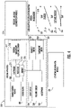
- FIG. 4 illustrates a block diagram of the sensing apparatus 210 of the sensing system of FIGs. 2 and 3 . It should be appreciated that, although particular systems are separately defined in the schematic block diagram of FIG. 4 , each or any of the systems may be otherwise combined or separated via hardware and/or software. As shown in FIG. 4 , the sensing apparatus 210 may include a controller 212, a plurality of sensors 217 in communication with the controller 212, a communication module 220 in communication with the controller 212, and a power source 222 electrically connected to the controller 212.
- the plurality of sensors 217 includes an inertial measurement unit (IMU) sensor 218 configured to detect sensor data 202 including accelerations 312 of the sensing apparatus 210 and the elevator car 103 when the sensing apparatus 210 is attached to the elevator car 103.
- the IMU sensor 218 may be a sensor, such as, for example, an accelerometer, a gyroscope, or a similar sensor known to one of skill in the art.
- the accelerations 312 detected by the IMU sensor 218 may include accelerations 312 as well as derivatives or integrals of accelerations, such as, for example, velocity, jerk, jounce, snap... etc.
- the IMU sensor 218 is in communication with the controller 212 of the sensing apparatus 210.
- the plurality of sensors 217 includes a pressure sensor 228 is configured to detect sensor data 202 including pressure data 314, such as, for example, atmospheric air pressure within the elevator shaft 117.
- the pressure sensor 228 may be a pressure altimeter or barometric altimeter in two non-limiting examples.
- the pressure sensor 228 is in communication with the controller 212.
- the controller 212 of the sensing apparatus 210 includes a processor 214 and an associated memory 216 comprising computer-executable instructions that, when executed by the processor 214, cause the processor 214 to perform various operations, such as, for example, edge pre-processing or processing the sensor data 202 collected by the IMU sensor 218, the light sensor 226, the pressure sensor 228, the microphone 230, the humidity sensor 232, and the temperature sensor 234.
- the controller 212 may process the accelerations 312 and/or the pressure data 314 in order to determine a probable location of the elevator car 103, discussed further below.
- the processor 214 may be but is not limited to a single-processor or multi-processor system of any of a wide array of possible architectures, including field programmable gate array (FPGA), central processing unit (CPU), application specific integrated circuits (ASIC), digital signal processor (DSP) or graphics processing unit (GPU) hardware arranged homogenously or heterogeneously.
- the memory 216 may be a storage device, such as, for example, a random access memory (RAM), read only memory (ROM), or other electronic, optical, magnetic or any other computer readable medium.
- the power source 222 of the sensing apparatus 210 is configured to store and supply electrical power to the sensing apparatus 210.
- the power source 222 may include an energy storage system, such as, for example, a battery system, capacitor, or other energy storage system known to one of skill in the art.
- the power source 222 may also generate electrical power for the sensing apparatus 210.
- the power source 222 may also include an energy generation or electricity harvesting system, such as, for example synchronous generator, induction generator, or other type of electrical generator known to one of skill in the art.
- the sensing apparatus 210 includes a communication module 220 configured to allow the controller 212 of the sensing apparatus 210 to communicate with the remote device 280 and/or controller 115 through at least one of short-range wireless protocols 203 and long-range wireless protocols 204.
- the communication module 220 may be configured to communicate with the remote device 280 using short-range wireless protocols 203, such as, for example, Bluetooth, Wi-Fi, HaLow (801.11ah), Wireless M-Bus, zWave, ZigBee, or other short-range wireless protocol known to one of skill in the art.
- the communication module 220 is configured to transmit the sensor data 202 to a local gateway device 240 and the local gateway device 240 is configured to transmit the sensor data 202 to a remote device 280 through a network 250, as described above.
- the communication module 220 may be configured to communicate with the remote device 280 using long-range wireless protocols 204, such as for example, cellular, LTE (NB-IoT, CAT M1), LoRa, Ingenu, SigFox, Satellite, or other long-range wireless protocol known to one of skill in the art.
- long-range wireless protocols 204 the communication module 220 is configured to transmit the sensor data 202 to a remote device 280 through a network 250.
- the short-range wireless protocol 203 is sub GHz Wireless M-Bus.
- the long-range wireless protocol is SigFox.
- the long-range wireless protocol is LTE NB-IoT or CAT M1 with 2G fallback.
- the sensing apparatus 210 includes a location determination module 330 configured to determine a location (i.e., position) of the elevator car 103 within the elevator shaft 117.
- the location of the elevator car 103 may be fixed locations along the elevator shaft 117, such as for example, the landings 125 of the elevator shaft 117.
- the locations may be equidistantly spaced apart along the elevator shaft 117 such as, for example, 5 meters or any other selected distance. Alternatively, the locations may be or intermittently spaced apart along the elevator shaft 117.
- the location determination module 330 may utilize various approaches to determine a location of the elevator car 103 within the elevator shaft 117.
- the location determination module 330 may be configured to determine a location of the elevator car 103 within the elevator shaft 117 using at least one of a pressure location determination module 310 and an acceleration location determination module 320.
- the acceleration location determination module 320 is configured to determine a distance traveled of the elevator car 103 within the elevator shaft 117 in response to the acceleration of the elevator car 103 detected along the Y axis.
- the sensing apparatus 210 may detect an acceleration along the Y axis shown at 322 and may integrate the acceleration to get a velocity of the elevator car 103 at 324.
- the sensing apparatus 210 may also integrate the velocity of the elevator car 103 to determine a distance traveled by the elevator car 103 within the elevator shaft 117 during the acceleration 312 detected at 322.
- the direction of travel of the elevator car 103 may also be determined in response to the acceleration 312 detected.
- the location determination module 330 may then determine the location of the elevator car 103 within the elevator shaft 117 in response to a starting location and a distance traveled away from that starting location.
- the starting location may be based upon tracking the past operation and/or movement of the elevator car 103.
- the pressure location determination module 310 is configured to detect an atmospheric air pressure within the elevator shaft 117 when the elevator car 103 is in motion and/or stationary using the pressure sensor 228.
- the pressure detected by the pressure sensor 228 may be associated with a location (e.g., height, elevation) within the elevator shaft 117 through either a look up table or a calculation of altitude using the barometric pressure change in two non-limiting embodiments.
- the direction of travel of the elevator car 103 may also be determined in response to the change in pressure detected via the pressure data 314.
- the pressure sensor 228 may need to periodically detect a baseline pressure to account for changes in atmospheric pressure due to local weather conditions. For example, this baseline pressure may need to be detected daily, hourly, or weekly in non-limiting embodiments.
- the baseline pressure may be detected whenever the elevator car 103 is stationary, or at certain intervals when the elevator car 103 is stationary and/or at a known location.
- the acceleration of the elevator car 103 may also need to be detected to know when the elevator car 103 is stationary and then when the elevator car 103 is stationary the sensing apparatus 210 may need to be offset to compensate the sensor drift and environment drift.
- the pressure location determination module 310 may be used to verify and/or modify a location of the elevator car 102 within the elevator shaft 117 determined by the acceleration location determination module 320.
- the acceleration location determination module 320 may be used to verify and/or modify a location of the elevator car 102 within the elevator shaft 117 determined by the pressure location determination module 310.
- the pressure location determination module 310 may be prompted to determine a location of the elevator car 103 within the elevator shaft 117 in response to an acceleration detected by the IMU sensor 218.
- FIG. 5 shows a flow chart of a method 500 of monitoring motion a conveyance apparatus within a conveyance system, in accordance with an embodiment of the disclosure.
- the conveyance system is an elevator system 101 and the conveyance apparatus is an elevator car 103.
- the method 500 may be performed by at least one of the sensing apparatus 210, the controller 115, and the remote device 280.
- a first atmospheric air pressure is detected proximate the conveyance apparatus at the first time using a pressure sensor 228 located on the conveyance apparatus.
- a second atmospheric air pressure is detected proximate the conveyance apparatus at a second time using the pressure sensor 228 located on the conveyance apparatus.
- a change in atmospheric air pressure proximate the conveyance apparatus is determined in response to the first atmospheric air pressure and the second atmospheric air pressure.
- a height change of a conveyance apparatus is detected in response to the change in atmospheric air pressure proximate the conveyance apparatus.
- the height change is confirmed or disconfirmed using at least one of a rate of change in atmospheric air pressure prior to the first time, an acceleration of the conveyance apparatus, a rate of change in static atmospheric air pressure, a rate of change in temperature, and a rate of change in relative humidity detection
- Weather changes that bring changes in local air pressure may provide false readings to the method 500, thus additional parameters may be used to confirm movement of the conveyance apparatus, such as, for example, local weather parameters, temperature, relative humidity, static atmospheric air pressure, or acceleration.
- Local weather parameters may change along with pressure, such as, for example, temperature and relative humidity.
- Static pressure is measure at a static or stationary location off of the conveyance apparatus, which moves. Thereby, a change in static atmospheric air pressure may be solely caused by the weather.
- Acceleration may be used to disconfirm movement of the conveyance apparatus detecting acceleration first, which prompts the controller 115 to then detect the first atmospheric air pressure and the second atmospheric air pressure.
- the method 500 may further include that an acceleration of the conveyance apparatus is detected and then detection of the first atmospheric air pressure proximate the conveyance apparatus at the first time using a pressure sensor located on the conveyance apparatus is commanded and detection of the second atmospheric air pressure proximate the conveyance apparatus at a second time using the pressure sensor located on the conveyance apparatus is commanded.
- a threshold speed indicating motion e.g. ⁇ 0.6 m/s equivalent
- the rate of change in atmospheric air pressure indicates a speed of 0.5 m/s, which is lower than a threshold speed indicating motion equivalent to 0.6 m/s
- the 0.5 m/s may be subtracted from the 1.5 m/s, thus resulting in 1.0 m/s of actual speed. Height can then be determined using the rate of speed of 1.0 m/s and the time traveled.
- the method 500 further comprises detecting a rate of change in atmospheric air pressure prior to the first time; determining that the conveyance apparatus was not moving prior to the first time in response to the rate of change in atmospheric air pressure prior to the first time; determining a rate of change in atmospheric air pressure between the first time and the second time; and adjusting the height change in response to a difference between the rate of change in atmospheric air pressure prior to the first time and the rate of change in atmospheric air pressure between the first time and the second time.
- Static atmospheric air pressure, detected by the static pressure senor 314A may be used to disconfirm movement of the conveyance apparatus.
- the method 500 may further include that a first static atmospheric air pressure proximate the conveyance apparatus is detected at about the first time using a static pressure sensor 228A located off of the conveyance apparatus and a second static atmospheric air pressure proximate the conveyance apparatus at is detected about the second time using the static pressure sensor 228A located off of the conveyance apparatus.
- the rate of change in static atmospheric air pressure proximate the conveyance apparatus is determined between the first time and the second time in response to the first static atmospheric air pressure, the second static atmospheric air pressure, the first time, and the second time.
- the height change may be disconfirmed in response to determining that the conveyance apparatus has not moved between the first time and the second time.
- the pressure sensor 228 located on the conveyance apparatus may detect a pressure change however that pressure change may be confirmed or disconfirmed by the static pressure sensor 228A located off of the conveyance apparatus.
- the static pressure sensor 228A detects a pressure change that may be attributed to a weather change
- the pressure change detected by the pressure sensors 228 may be adjusted or disconfirmed. Once disconfirmed, the controller 115 may reset floor level detection and learning.
- the height change determined in block 510 may be adjusted in response to the rate of change in static atmospheric air pressure.
- the static atmospheric air pressure may be subtracted from the atmospheric air pressure detected by the pressure sensor 228.
- the pressure sensor 228 located on the conveyance apparatus may detect a pressure change however that pressure change may be adjusted by the static pressure sensor 228A located off of the conveyance apparatus.
- the static pressure sensor 228A detects a pressure change that may be attributed to a weather change while the conveyance apparatus is moving, then the pressure change detected by the pressure sensors 228 may be adjusted to remove the pressure change attributed to the weather change, thus leaving only the pressure change attributed to the movement of the conveyance apparatus.
- Temperature detected by the temperature sensor 234 may be used to confirm movement of the conveyance apparatus.
- the method 500 may include that a first temperature proximate the conveyance apparatus is detected at about the first time and a second temperature proximate the conveyance apparatus at about the second time.
- the rate of change in temperature proximate the conveyance apparatus between the first time and the second time is determined in response to the first temperature, the second temperature, the first time, and the second time.
- the rate of change in temperature may be determined to be below a threshold temperature rate of change and it may be determined that the conveyance apparatus has moved between the first time and the second time in response to determining that the rate of change in temperature is below the threshold temperature rate of change.
- the height change may be confirmed in response to determining that the conveyance apparatus has moved between the first time and the second time.
- the pressure sensor 228 located on the conveyance apparatus may detect a pressure change however that pressure change may be confirmed or disconfirmed by the temperature sensor 234. For example, if the temperature sensor 234 does not detect a temperature change that may be attributed to a weather change while the conveyance apparatus is moving, then the pressure change detected by the pressure sensors 228 may be confirmed.
- the rate of change in relative humidity may be determined to be above a threshold relative humidity rate of change and it may be determined that the conveyance apparatus has not moved between the first time and the second time in response to determining that the rate of change in relative humidity is above the threshold relative humidity rate of change. Then the height change may be disconfirmed in response to determining that the conveyance apparatus has not moved between the first time and the second time.
- the pressure sensor 228 located on the conveyance apparatus may detect a pressure change however that pressure change may be confirmed or disconfirmed by the humidity sensor 232. For example, if the humidity sensors 232 detects a change in relative humidity that may be attributed to a weather change while the conveyance apparatus is moving, then the pressure change detected by the pressure sensors 228 may be adjusted or disconfirmed.
- the height change may be confirmed in response to determining that the conveyance apparatus has moved between the first time and the second time.
- the pressure sensor 228 located on the conveyance apparatus may detect a pressure change however that pressure change may be confirmed or disconfirmed by the humidity sensor 232. For example, if the humidity sensor 232 does not detect a change in relative humidity that may be attributed to a weather change while the conveyance apparatus is moving, then the pressure change detected by the pressure sensors 228 may be confirmed.
- the method 500 may also include that the pressure sensor 228 may be utilized to detect the initiation of movement of the conveyance apparatus and then the double integral of acceleration detected by the IMU sensor 218 may be utilized to detect the location of the conveyance apparatus within the conveyance system.
Landscapes
- Engineering & Computer Science (AREA)
- Automation & Control Theory (AREA)
- Physics & Mathematics (AREA)
- General Physics & Mathematics (AREA)
- Computer Networks & Wireless Communication (AREA)
- Radar, Positioning & Navigation (AREA)
- Remote Sensing (AREA)
- Elevator Control (AREA)
- Control Of Conveyors (AREA)
- Indicating And Signalling Devices For Elevators (AREA)
Claims (13)
- Verfahren (500) zum Überwachen einer Bewegung einer Fördervorrichtung in einem Fördersystem, wobei das Verfahren Folgendes umfasst:Erkennen eines ersten atmosphärischen Luftdrucks in der Nähe der Fördervorrichtung zu einem ersten Zeitpunkt unter Verwendung eines Drucksensors (228), der sich an der Fördervorrichtung (504) befindet;Erkennen eines zweiten atmosphärischen Luftdrucks in der Nähe der Fördervorrichtung zu einem zweiten Zeitpunkt unter Verwendung des Drucksensors, der sich an der Fördervorrichtung (506) befindet;Bestimmen einer Änderung des atmosphärischen Luftdrucks in der Nähe der Fördervorrichtung als Reaktion auf den ersten atmosphärischen Luftdruck und den zweiten atmosphärischen Luftdruck (508);Erkennen einer Höhenänderung einer Fördervorrichtung als Reaktion auf mindestens die Änderung des atmosphärischen Luftdrucks in der Nähe der Fördervorrichtung (510); undBestätigen oder Nicht-Bestätigen der Höhenänderung unter Verwendung mindestens eines von einer Änderungsrate eines atmosphärischen Luftdrucks vor dem ersten Zeitpunkt, einer Beschleunigung der Fördervorrichtung, einer Änderungsrate eines statischen atmosphärischen Luftdrucks, einer Änderungsrate einer Temperatur und einer Änderungsrate einer relativen Feuchtigkeitserkennung; gekennzeichnet durch:Erkennen einer Änderungsrate eines atmosphärischen Luftdrucks vor dem ersten Zeitpunkt;Bestimmen, dass sich die Fördervorrichtung vor dem ersten Zeitpunkt nicht bewegt hat, als Reaktion auf die Änderungsrate eines atmosphärischen Luftdrucks vor dem ersten Zeitpunkt;Bestimmen einer Änderungsrate eines atmosphärischen Luftdrucks zwischen dem ersten Zeitpunkt und dem zweiten Zeitpunkt; und Einstellen der Höhenänderung als Reaktion auf eine Differenz zwischen der Änderungsrate eines atmosphärischen Luftdrucks vor dem ersten Zeitpunkt und einer Änderungsrate eines atmosphärischen Luftdrucks zwischen dem ersten Zeitpunkt und dem zweiten Zeitpunkt.
- Verfahren nach Anspruch 1, ferner umfassend:Erkennen einer Beschleunigung der Fördervorrichtung;Befehlen eines Erkennens des ersten atmosphärischen Luftdrucks in der Nähe der Fördervorrichtung zu dem ersten Zeitpunkt unter Verwendung eines Drucksensors, der sich an der Fördervorrichtung befindet (228); undBefehlen eines Erkennens des zweiten atmosphärischen Luftdrucks in der Nähe der Fördervorrichtung zu einem zweiten Zeitpunkt unter Verwendung des Drucksensors, der sich an der Fördervorrichtung befindet.
- Verfahren nach einem der Ansprüche 1 oder 2, ferner umfassend:Erkennen eines ersten statischen atmosphärischen Luftdrucks in der Nähe der Fördervorrichtung zu etwa dem ersten Zeitpunkt unter Verwendung eines statischen Drucksensors (228A), der sich außerhalb der Fördervorrichtung befindet;Erkennen eines zweiten statischen atmosphärischen Luftdrucks in der Nähe der Fördervorrichtung zu etwa dem zweiten Zeitpunkt unter Verwendung des statischen Drucksensors, der sich außerhalb der Fördervorrichtung befindet;Bestimmen der Änderungsrate eines statischen atmosphärischen Luftdrucks in der Nähe der Fördervorrichtung zwischen dem ersten Zeitpunkt und dem zweiten Zeitpunkt als Reaktion auf den ersten statischen atmosphärischen Luftdruck, den zweiten statischen atmosphärischen Luftdruck, den ersten Zeitpunkt und den zweiten Zeitpunkt;Bestimmen, dass die Änderungsrate eines statischen atmosphärischen Luftdrucks über einer Schwellenwert-Änderungsrate eines statischen atmosphärischen Luftdrucks liegt;Bestimmen, dass sich die Fördervorrichtung zwischen dem ersten Zeitpunkt und dem zweiten Zeitpunkt nicht bewegt hat, als Reaktion auf ein Bestimmen, dass die Änderungsrate eines atmosphärischen Luftdrucks über der Schwellenwert-Änderungsrate eines atmosphärischen Luftdrucks liegt;
undNicht-Bestätigen der Höhenänderung als Reaktion auf ein Bestimmen, dass sich die Fördervorrichtung zwischen dem ersten Zeitpunkt und dem zweiten Zeitpunkt nicht bewegt hat. - Verfahren nach einem vorhergehenden Anspruch, ferner Folgendes umfassend:Erkennen eines ersten statischen atmosphärischen Luftdrucks in der Nähe der Fördervorrichtung etwa zu dem ersten Zeitpunkt unter Verwendung eines statischen Drucksensors (228A), der sich außerhalb der Fördervorrichtung befindet,Erkennen eines zweiten statischen atmosphärischen Luftdrucks in der Nähe der Fördervorrichtung zu etwa dem zweiten Zeitpunkt unter Verwendung des statischen Drucksensors, der sich außerhalb der Fördervorrichtung befindet;Bestimmen der Änderungsrate eines statischen atmosphärischen Luftdrucks in der Nähe der Fördervorrichtung zwischen dem ersten Zeitpunkt und dem zweiten Zeitpunkt als Reaktion auf den ersten statischen atmosphärischen Luftdruck, den zweiten statischen atmosphärischen Luftdruck, den ersten Zeitpunkt und den zweiten Zeitpunkt; undEinstellen der Höhenänderung als Reaktion auf die Änderungsrate eines statischen atmosphärischen Luftdrucks.
- Verfahren nach einem vorstehenden Anspruch, ferner umfassend:Erkennen einer ersten Temperatur in der Nähe der Fördervorrichtung etwa zu dem ersten Zeitpunkt,Erkennen einer zweiten Temperatur in der Nähe der Fördervorrichtung etwa zu dem zweiten Zeitpunkt,Bestimmen der Änderungsrate einer Temperatur in der Nähe der Fördervorrichtung zwischen dem ersten Zeitpunkt und dem zweiten Zeitpunkt als Reaktion auf die erste Temperatur, die zweite Temperatur, den ersten Zeitpunkt und den zweiten Zeitpunkt;Bestimmen, dass die Änderungsrate einer Temperatur über einem Schwellenwert für eine Änderungsrate einer Temperatur liegt, Bestimmen, dass sich die Fördervorrichtung zwischen dem ersten Zeitpunkt und dem zweiten Zeitpunkt nicht bewegt hat, als Reaktion auf ein Bestimmen, dass die Änderungsrate einer Temperatur über der Schwellenwert-Änderungsrate einer Temperatur liegt; undNicht-Bestätigen der Höhenänderung als Reaktion auf ein Bestimmen, dass sich die Fördervorrichtung zwischen dem ersten Zeitpunkt und dem zweiten Zeitpunkt nicht bewegt hat.
- Verfahren nach einem vorstehenden Anspruch, ferner umfassend:Erkennen einer ersten Temperatur in der Nähe der Fördervorrichtung etwa zu dem ersten Zeitpunkt;Erkennen einer zweiten Temperatur in der Nähe der Fördervorrichtung zu etwa dem zweiten Zeitpunkt;Bestimmen der Änderungsrate einer Temperatur in der Nähe der Fördervorrichtung zwischen dem ersten Zeitpunkt und dem zweiten Zeitpunkt als Reaktion auf die erste Temperatur, die zweite Temperatur, den ersten Zeitpunkt und den zweiten Zeitpunkt;Bestimmen, dass die Änderungsrate einer Temperatur unter einer Schwellenwert-Änderungsrate einer Temperaturliegt;Bestimmen, dass sich die Fördervorrichtung zwischen dem ersten Zeitpunkt und dem zweiten Zeitpunkt bewegt hat, als Reaktion auf ein Bestimmen, dass die Änderungsrate einer Temperatur unter der Schwellenwert-Änderungsrate einer Temperatur liegt; undBestätigen der Höhenänderung als Reaktion auf ein Bestimmen, dass sich die Fördervorrichtung zwischen dem ersten Zeitpunkt und dem zweiten Zeitpunkt bewegt hat.
- Verfahren nach einem vorstehenden Anspruch, ferner Folgendes umfassend:Erkennen einer ersten relativen Luftfeuchtigkeit in der Nähe der Fördervorrichtung etwa zu dem ersten Zeitpunkt,Erkennen einer zweiten relativen Luftfeuchtigkeit in der Nähe der Fördervorrichtung etwa zu dem zweiten Zeitpunkt,Bestimmen der Änderungsrate einer relativen Feuchtigkeit in der Nähe der Fördervorrichtung zwischen dem ersten Zeitpunkt und dem zweiten Zeitpunkt als Reaktion auf die erste relative Feuchtigkeit, die zweite relative Feuchtigkeit, den ersten Zeitpunkt und den zweiten Zeitpunkt;Bestimmen, dass die Änderungsrate einer relativen Luftfeuchtigkeit über einem Schwellenwert-Änderungsrate einer relativen Luftfeuchtigkeit liegt;Bestimmen, dass sich die Fördervorrichtung zwischen dem ersten Zeitpunkt und dem zweiten Zeitpunkt nicht bewegt hat, als Reaktion auf ein Bestimmen, dass die Änderungsrate einer relativen Luftfeuchtigkeit über dem Schwellenwert der Änderungsrate einer relativen Luftfeuchtigkeit liegt; undNicht-Bestätigen der Höhenänderung als Reaktion auf das Bestimmen, dass sich die Fördervorrichtung zwischen dem ersten Zeitpunkt und dem zweiten Zeitpunkt nicht bewegt hat.
- Verfahren nach einem vorhergehenden Anspruch, ferner Folgendes umfassend:Erkennen einer ersten relativen Feuchtigkeit in der Nähe der Fördervorrichtung etwa zu dem ersten Zeitpunkt;Erkennen einer zweiten relativen Luftfeuchtigkeit in der Nähe der Fördervorrichtung etwa zu dem zweiten Zeitpunkt;Bestimmen der Änderungsrate einer relativen Feuchtigkeit in der Nähe der Fördervorrichtung zwischen dem ersten Zeitpunkt und dem zweiten Zeitpunkt als Reaktion auf die erste relative Feuchtigkeit, die zweite relative Feuchtigkeit, den ersten Zeitpunkt und den zweiten Zeitpunkt;Bestimmen, dass die Änderungsrate einer relativen Feuchtigkeit unter einem Schwellenwert einer Änderungsrate einer relativen Feuchtigkeit liegt;Bestimmen, dass sich die Fördervorrichtung zwischen dem ersten Zeitpunkt und dem zweiten Zeitpunkt bewegt hat, als Reaktion auf ein Bestimmen, dass die Änderungsrate einer relativen Feuchtigkeit unter der Schwellenwert-Änderungsrate einer relativen Feuchtigkeit liegt; undBestätigen der Höhenänderung als Reaktion auf ein Bestimmen, dass sich die Fördervorrichtung zwischen dem ersten Zeitpunkt und dem zweiten Zeitpunkt bewegt hat.
- Verfahren nach einem vorstehenden Anspruch, wobei das Fördersystem ein Aufzugssystem (101) ist und die Fördervorrichtung eine Aufzugskabine (103) ist.
- Erfassungsvorrichtung (210) zum Überwachen einer Fördervorrichtung innerhalb eines Fördersystems, wobei die Erfassungsvorrichtung Folgendes umfasst:einen Prozessor (214); undeinen Speicher (216), der computerausführbare Anweisungen umfasst, die, wenn sie von dem Prozessor ausgeführt werden, den Prozessor dazu zu veranlassen, Operationen durchzuführen, wobei die Operationen Folgendes umfassen:Erkennen eines ersten atmosphärischen Luftdrucks in der Nähe der Fördervorrichtung zu einem ersten Zeitpunkt unter Verwendung eines Drucksensors (228), der sich an der Fördervorrichtung befindet,Erkennen eines zweiten atmosphärischen Luftdrucks in der Nähe der Fördervorrichtung zu einem zweiten Zeitpunkt unter Verwendung des Drucksensors, der sich an der Fördervorrichtung befindet;Bestimmen einer Änderung eines atmosphärischen Luftdrucks in der Nähe der Fördervorrichtung als Reaktion auf den ersten atmosphärischen Luftdruck und dem zweiten atmosphärischen Luftdruck;Erkennen einer Höhenänderung einer Fördervorrichtung als Reaktion auf mindestens die Änderung eines atmosphärischen Luftdrucks in der Nähe der Fördervorrichtung; undBestätigen oder Nicht-Bestätigen der Höhenänderung unter Verwendung von mindestens einer Änderungsrate eines atmosphärischen Luftdrucks, einer Beschleunigung der Fördervorrichtung, einer Änderungsrate eines statischen atmosphärischen Luftdrucks, einer Änderungsrate einer Temperatur und einer Änderungsrate eines Erkennens einer relativen Luftfeuchtigkeit, dadurch gekennzeichnet, dass die Vorgänge ferner umfassen:Erkennen einer Änderungsrate eines atmosphärischen Luftdrucks vor dem ersten Zeitpunkt;Bestimmen, dass sich die Fördervorrichtung vor dem ersten Zeitpunkt nicht bewegt hat, als Reaktion auf die Änderungsrate eines atmosphärischen Luftdrucks vor dem ersten Zeitpunkt,Bestimmen einer Änderungsrate eines atmosphärischen Luftdrucks zwischen dem ersten Zeitpunkt und dem zweiten Zeitpunkt; undEinstellen der Höhenänderung als Reaktion auf eine Differenz zwischen der Änderungsrate eines atmosphärischen Luftdrucks vor dem ersten Zeitpunkt und der Änderungsrate eines atmosphärischen Luftdrucks zwischen dem ersten Zeitpunkt und dem zweiten Zeitpunkt.
- System nach Anspruch 10, wobei die Operationen ferner Folgendes umfassen:Erkennen einer Beschleunigung der Fördervorrichtung zu dem ersten Zeitpunkt;Befehlen eines Erkennens des ersten atmosphärischen Luftdrucks in der Nähe der Fördervorrichtung zu dem ersten Zeitpunkt unter Verwendung eines Drucksensors (228), der sich an der Fördervorrichtung befindet; undBefehlen eines Erkennens des zweiten atmosphärischen Luftdrucks in der Nähe der Fördervorrichtung zu einem zweiten Zeitpunkt unter Verwendung des Drucksensors, der sich an der Fördervorrichtung befindet.
- System nach einem der Ansprüche 10 oder 11, wobei die Operationen ferner Folgendes umfassen:Erkennen eines ersten statischen atmosphärischen Luftdrucks in der Nähe der Fördervorrichtung zu etwa dem ersten Zeitpunkt unter Verwendung eines statischen Drucksensors (228A), der sich außerhalb der Fördervorrichtung befindet;Erkennen eines zweiten statischen atmosphärischen Luftdrucks in der Nähe der Fördervorrichtung zu etwa dem zweiten Zeitpunkt unter Verwendung des statischen Drucksensors, der sich außerhalb der Fördervorrichtung befindet;Bestimmen der Änderungsrate eines statischen atmosphärischen Luftdrucks in der Nähe der Fördervorrichtung zwischen dem ersten Zeitpunkt und dem zweiten Zeitpunkt als Reaktion auf ersten statischen atmosphärischen Luftdruck, den zweiten statischen atmosphärischen Luftdruck, den ersten Zeitpunkt und den zweiten Zeitpunkt;Bestimmen, dass die Änderungsrate eines statischen atmosphärischen Luftdrucks über einem Schwellenwert für die Änderungsrate eines statischen atmosphärischen Luftdrucks liegt;Bestimmen, dass sich die Fördervorrichtung zwischen dem ersten Zeitpunkt und dem zweiten Zeitpunkt nicht bewegt hat, als Reaktion auf ein Bestimmen, dass die Änderungsrate eines atmosphärischen Luftdrucks über der Schwellenwert-Änderungsrate eines atmosphärischen Luftdrucks liegt; undNicht-Bestätigen der Höhenänderung als Reaktion auf ein Bestimmen, dass sich die Fördervorrichtung zwischen dem ersten Zeitpunkt und dem zweiten Zeitpunkt nicht bewegt hat.
- System nach einem der Ansprüche 10 bis 12, wobei das Fördersystem ein Aufzugssystem (101) und die Fördervorrichtung eine Aufzugskabine (103) ist.
Applications Claiming Priority (1)
| Application Number | Priority Date | Filing Date | Title |
|---|---|---|---|
| US16/527,261 US12084310B2 (en) | 2019-07-31 | 2019-07-31 | Pressure sensor algorithm to detect elevator status information |
Publications (2)
| Publication Number | Publication Date |
|---|---|
| EP3771680A1 EP3771680A1 (de) | 2021-02-03 |
| EP3771680B1 true EP3771680B1 (de) | 2022-07-06 |
Family
ID=70738338
Family Applications (1)
| Application Number | Title | Priority Date | Filing Date |
|---|---|---|---|
| EP20174902.5A Active EP3771680B1 (de) | 2019-07-31 | 2020-05-15 | Drucksensoralgorithmus zur erkennung von aufzugsstatusinformationen |
Country Status (3)
| Country | Link |
|---|---|
| US (1) | US12084310B2 (de) |
| EP (1) | EP3771680B1 (de) |
| CN (1) | CN112299177B (de) |
Families Citing this family (4)
| Publication number | Priority date | Publication date | Assignee | Title |
|---|---|---|---|---|
| US11535491B2 (en) * | 2019-03-28 | 2022-12-27 | Otis Elevator Company | Verification of trapped passenger alarm |
| US11987472B2 (en) * | 2019-05-01 | 2024-05-21 | Otis Elevator Company | Air pressure sensor algorithm to detect elevator direction of motion |
| US12084310B2 (en) * | 2019-07-31 | 2024-09-10 | Otis Elevator Company | Pressure sensor algorithm to detect elevator status information |
| US11059702B2 (en) * | 2019-11-15 | 2021-07-13 | Otis Elevator Company | Combined dashboard weather, escalator condition based maintenance data |
Family Cites Families (41)
| Publication number | Priority date | Publication date | Assignee | Title |
|---|---|---|---|---|
| US6298287B1 (en) | 2000-07-24 | 2001-10-02 | Litton Systems, Inc. | System and method of compensating for pressure sensor errors and noise in inertial vertical loop data |
| JP3810669B2 (ja) | 2001-11-19 | 2006-08-16 | セイコーインスツル株式会社 | 移動検出型高度計 |
| ZA200307740B (en) | 2002-10-29 | 2004-07-02 | Inventio Ag | Device and method for remote maintenance of a lift. |
| US7162368B2 (en) | 2004-11-09 | 2007-01-09 | Honeywell International Inc. | Barometric floor level indicator |
| DE102006033605B8 (de) * | 2006-07-18 | 2008-07-10 | Fraba Ag | Vorrichtung und Verfahren zur Bestimmung von Vertikalpositionen |
| WO2009101566A1 (en) | 2008-02-15 | 2009-08-20 | Koninklijke Philips Electronics N.V. | Compensating pressure sensor measurements |
| DE102009041330A1 (de) | 2009-09-15 | 2011-04-07 | Henning Gmbh | Verbrauchersteuereinrichtung und Verfahren zur Betätigung wenigstens eines Verbrauchers eines Aufzugs |
| CN102471017B (zh) | 2009-09-22 | 2014-07-16 | 诺亚科技株式会社 | 利用加速度传感器的升降机层运行信息提示及显示装置 |
| CN102311024B (zh) * | 2010-07-01 | 2013-06-05 | 上海三菱电梯有限公司 | 用于检测电梯轿厢位置和速度的装置 |
| FI124586B (fi) | 2012-02-03 | 2014-10-31 | Suunto Oy | Menetelmä ja laite korkeuden määrittämiseksi |
| JP6106198B2 (ja) | 2012-03-13 | 2017-03-29 | コーニンクレッカ フィリップス エヌ ヴェKoninklijke Philips N.V. | 空気圧センサを使用する装置の高さ変化の監視方法 |
| JP6107409B2 (ja) | 2013-05-21 | 2017-04-05 | 富士ゼロックス株式会社 | 位置特定処理装置及び位置特定処理プログラム |
| JP6114175B2 (ja) | 2013-12-24 | 2017-04-12 | 京セラ株式会社 | 携帯電子機器、制御方法、及び制御プログラム |
| US9970757B2 (en) | 2014-01-08 | 2018-05-15 | Qualcomm Incorporated | Method and apparatus for positioning with always on barometer |
| US20170225921A1 (en) * | 2014-07-28 | 2017-08-10 | Otis Elevator Company | Elevator car location sensing system |
| US10112801B2 (en) | 2014-08-05 | 2018-10-30 | Richard Laszlo Madarasz | Elevator inspection apparatus with separate computing device and sensors |
| CN104748722B (zh) | 2015-03-13 | 2017-09-08 | 中国科学院光电研究院 | 利用卫星定位信息实时校准气压测高结果的高程定位方法 |
| US9574964B2 (en) | 2015-07-07 | 2017-02-21 | Toyota Jidosha Kabushiki Kaisha | Mobile computer atmospheric barometric pressure system |
| CN108317996B (zh) | 2015-08-27 | 2021-06-29 | 华为终端有限公司 | 一种确定楼层方法、相关设备和系统 |
| SG11201804016YA (en) * | 2015-12-02 | 2018-06-28 | Inventio Ag | Monitoring and/or registering a position of a tool in an elevator shaft |
| CN105712142B (zh) | 2016-03-22 | 2018-01-12 | 上海点络信息技术有限公司 | 一种电梯运行状态的检测系统及检测方法 |
| EP3264035A1 (de) | 2016-07-01 | 2018-01-03 | INTEL Corporation | System und verfahren zur innenhöhenbestimmung |
| US10254188B2 (en) | 2016-09-09 | 2019-04-09 | Qualcomm Incorporated | Adaptive pressure sensor sampling rate |
| CN106705935A (zh) | 2016-12-02 | 2017-05-24 | 上海华测导航技术股份有限公司 | 多轴无人机高度更新方法 |
| EP3190075B1 (de) | 2016-12-12 | 2023-08-30 | Lift Technology GmbH | Überwachungseinheit für die überwachung eines aufzugs |
| CN106744120A (zh) | 2017-01-23 | 2017-05-31 | 大连奥远电子股份有限公司 | 一种采集电梯运行距离位置的系统 |
| KR101784399B1 (ko) | 2017-02-13 | 2017-10-17 | (주)씨프로 | 대기압 및 가속도센서를 이용한 승강기 카메라의 층 운행정보 인지시스템 |
| WO2018211655A1 (ja) | 2017-05-18 | 2018-11-22 | 三菱電機株式会社 | 位置検出装置、エレベーター制御装置及びエレベーターシステム |
| SG10201704952RA (en) | 2017-06-15 | 2019-01-30 | Surbana Tech Pte Ltd | Lift monitoring apparatus and system |
| US10578639B2 (en) * | 2017-08-28 | 2020-03-03 | Otis Elevator Company | Hybrid altimeter for measuring vertical velocity |
| CN107720467A (zh) * | 2017-09-14 | 2018-02-23 | 江门市冠田智能科技有限公司 | 电梯定位方法、装置及存储介质 |
| CN107651516B (zh) | 2017-09-27 | 2019-06-21 | 宁夏电通物联网科技股份有限公司 | 基于三轴气压霍尔的电梯楼层检测装置及检测系统及方法 |
| CN108562269A (zh) | 2018-01-10 | 2018-09-21 | 云南电网有限责任公司电力科学研究院 | 一种相对高度测量方法及装置 |
| CN108458688B (zh) | 2018-02-23 | 2021-02-23 | 珠海全志科技股份有限公司 | 高度与速度更新方法、模块及无人机 |
| GB2574644B (en) | 2018-06-13 | 2022-09-07 | Avire Ltd | A location system, method, and calibration method |
| CN108946367B (zh) | 2018-09-12 | 2021-05-25 | 广州瓦良格机器人科技有限公司 | 基于相对气压及高度误差校正的电梯运行检测方法及装置 |
| US10822199B2 (en) * | 2019-03-28 | 2020-11-03 | Otis Elevator Company | Sensor fusion of acceleration sensor and air pressure sensor information to estimate elevator floor level and position |
| US12084310B2 (en) * | 2019-07-31 | 2024-09-10 | Otis Elevator Company | Pressure sensor algorithm to detect elevator status information |
| US20210087017A1 (en) * | 2019-09-20 | 2021-03-25 | Otis Elevator Company | Estimation and presentation of area of interest for condition based monitoring on doors: door health heat map |
| US20210087018A1 (en) * | 2019-09-20 | 2021-03-25 | Otis Elevator Company | Air pressure floor table detection: statistical analysis of location |
| US20210094794A1 (en) * | 2019-09-27 | 2021-04-01 | Otis Elevator Company | Air pressure and acceleration sensor floor correction by elevator status information |
-
2019
- 2019-07-31 US US16/527,261 patent/US12084310B2/en active Active
-
2020
- 2020-05-15 EP EP20174902.5A patent/EP3771680B1/de active Active
- 2020-07-31 CN CN202010757699.1A patent/CN112299177B/zh active Active
Also Published As
| Publication number | Publication date |
|---|---|
| CN112299177B (zh) | 2022-07-12 |
| US20210032076A1 (en) | 2021-02-04 |
| US12084310B2 (en) | 2024-09-10 |
| CN112299177A (zh) | 2021-02-02 |
| EP3771680A1 (de) | 2021-02-03 |
Similar Documents
| Publication | Publication Date | Title |
|---|---|---|
| US10822199B2 (en) | Sensor fusion of acceleration sensor and air pressure sensor information to estimate elevator floor level and position | |
| EP3771680B1 (de) | Drucksensoralgorithmus zur erkennung von aufzugsstatusinformationen | |
| EP3693311B1 (de) | Fördervorrichtungpositionsbestimmung mithilfe von wahrscheinlichkeit | |
| EP3798170A1 (de) | Luftdruck- und beschleunigungssensorbodenkorrektur durch aufzugsstatusinformationen | |
| US20190367325A1 (en) | Wireless sensor for conveyance system monitoring | |
| CN111348498B (zh) | 用于电梯监测的虚拟传感器 | |
| EP3733583B1 (de) | Verteiltes gesundheitsniveau eines aufzugsschachts | |
| EP3715301A1 (de) | Verifizierung eines alarms eines eingeschlossenen passagiers | |
| EP3733581A1 (de) | Luftdrucksensoralgorithmus zur erkennung einer aufzugsbewegungsrichtung | |
| CN111924676B (zh) | 传感器融合门状态检测 | |
| US11718500B2 (en) | Customer behavior driven predictive maintenance | |
| US20220106158A1 (en) | Floor identification using magnetic signature referencing and sensor fusion |
Legal Events
| Date | Code | Title | Description |
|---|---|---|---|
| PUAI | Public reference made under article 153(3) epc to a published international application that has entered the european phase |
Free format text: ORIGINAL CODE: 0009012 |
|
| STAA | Information on the status of an ep patent application or granted ep patent |
Free format text: STATUS: THE APPLICATION HAS BEEN PUBLISHED |
|
| AK | Designated contracting states |
Kind code of ref document: A1 Designated state(s): AL AT BE BG CH CY CZ DE DK EE ES FI FR GB GR HR HU IE IS IT LI LT LU LV MC MK MT NL NO PL PT RO RS SE SI SK SM TR |
|
| AX | Request for extension of the european patent |
Extension state: BA ME |
|
| STAA | Information on the status of an ep patent application or granted ep patent |
Free format text: STATUS: REQUEST FOR EXAMINATION WAS MADE |
|
| 17P | Request for examination filed |
Effective date: 20210723 |
|
| RBV | Designated contracting states (corrected) |
Designated state(s): AL AT BE BG CH CY CZ DE DK EE ES FI FR GB GR HR HU IE IS IT LI LT LU LV MC MK MT NL NO PL PT RO RS SE SI SK SM TR |
|
| GRAP | Despatch of communication of intention to grant a patent |
Free format text: ORIGINAL CODE: EPIDOSNIGR1 |
|
| STAA | Information on the status of an ep patent application or granted ep patent |
Free format text: STATUS: GRANT OF PATENT IS INTENDED |
|
| INTG | Intention to grant announced |
Effective date: 20220118 |
|
| GRAS | Grant fee paid |
Free format text: ORIGINAL CODE: EPIDOSNIGR3 |
|
| GRAA | (expected) grant |
Free format text: ORIGINAL CODE: 0009210 |
|
| STAA | Information on the status of an ep patent application or granted ep patent |
Free format text: STATUS: THE PATENT HAS BEEN GRANTED |
|
| AK | Designated contracting states |
Kind code of ref document: B1 Designated state(s): AL AT BE BG CH CY CZ DE DK EE ES FI FR GB GR HR HU IE IS IT LI LT LU LV MC MK MT NL NO PL PT RO RS SE SI SK SM TR |
|
| REG | Reference to a national code |
Ref country code: AT Ref legal event code: REF Ref document number: 1502749 Country of ref document: AT Kind code of ref document: T Effective date: 20220715 Ref country code: CH Ref legal event code: EP |
|
| REG | Reference to a national code |
Ref country code: DE Ref legal event code: R096 Ref document number: 602020003847 Country of ref document: DE |
|
| REG | Reference to a national code |
Ref country code: IE Ref legal event code: FG4D |
|
| REG | Reference to a national code |
Ref country code: LT Ref legal event code: MG9D |
|
| REG | Reference to a national code |
Ref country code: NL Ref legal event code: MP Effective date: 20220706 |
|
| PG25 | Lapsed in a contracting state [announced via postgrant information from national office to epo] |
Ref country code: SE Free format text: LAPSE BECAUSE OF FAILURE TO SUBMIT A TRANSLATION OF THE DESCRIPTION OR TO PAY THE FEE WITHIN THE PRESCRIBED TIME-LIMIT Effective date: 20220706 Ref country code: RS Free format text: LAPSE BECAUSE OF FAILURE TO SUBMIT A TRANSLATION OF THE DESCRIPTION OR TO PAY THE FEE WITHIN THE PRESCRIBED TIME-LIMIT Effective date: 20220706 Ref country code: PT Free format text: LAPSE BECAUSE OF FAILURE TO SUBMIT A TRANSLATION OF THE DESCRIPTION OR TO PAY THE FEE WITHIN THE PRESCRIBED TIME-LIMIT Effective date: 20221107 Ref country code: NO Free format text: LAPSE BECAUSE OF FAILURE TO SUBMIT A TRANSLATION OF THE DESCRIPTION OR TO PAY THE FEE WITHIN THE PRESCRIBED TIME-LIMIT Effective date: 20221006 Ref country code: NL Free format text: LAPSE BECAUSE OF FAILURE TO SUBMIT A TRANSLATION OF THE DESCRIPTION OR TO PAY THE FEE WITHIN THE PRESCRIBED TIME-LIMIT Effective date: 20220706 Ref country code: LV Free format text: LAPSE BECAUSE OF FAILURE TO SUBMIT A TRANSLATION OF THE DESCRIPTION OR TO PAY THE FEE WITHIN THE PRESCRIBED TIME-LIMIT Effective date: 20220706 Ref country code: LT Free format text: LAPSE BECAUSE OF FAILURE TO SUBMIT A TRANSLATION OF THE DESCRIPTION OR TO PAY THE FEE WITHIN THE PRESCRIBED TIME-LIMIT Effective date: 20220706 Ref country code: FI Free format text: LAPSE BECAUSE OF FAILURE TO SUBMIT A TRANSLATION OF THE DESCRIPTION OR TO PAY THE FEE WITHIN THE PRESCRIBED TIME-LIMIT Effective date: 20220706 Ref country code: ES Free format text: LAPSE BECAUSE OF FAILURE TO SUBMIT A TRANSLATION OF THE DESCRIPTION OR TO PAY THE FEE WITHIN THE PRESCRIBED TIME-LIMIT Effective date: 20220706 |
|
| REG | Reference to a national code |
Ref country code: AT Ref legal event code: MK05 Ref document number: 1502749 Country of ref document: AT Kind code of ref document: T Effective date: 20220706 |
|
| PG25 | Lapsed in a contracting state [announced via postgrant information from national office to epo] |
Ref country code: PL Free format text: LAPSE BECAUSE OF FAILURE TO SUBMIT A TRANSLATION OF THE DESCRIPTION OR TO PAY THE FEE WITHIN THE PRESCRIBED TIME-LIMIT Effective date: 20220706 Ref country code: IS Free format text: LAPSE BECAUSE OF FAILURE TO SUBMIT A TRANSLATION OF THE DESCRIPTION OR TO PAY THE FEE WITHIN THE PRESCRIBED TIME-LIMIT Effective date: 20221106 Ref country code: HR Free format text: LAPSE BECAUSE OF FAILURE TO SUBMIT A TRANSLATION OF THE DESCRIPTION OR TO PAY THE FEE WITHIN THE PRESCRIBED TIME-LIMIT Effective date: 20220706 Ref country code: GR Free format text: LAPSE BECAUSE OF FAILURE TO SUBMIT A TRANSLATION OF THE DESCRIPTION OR TO PAY THE FEE WITHIN THE PRESCRIBED TIME-LIMIT Effective date: 20221007 |
|
| REG | Reference to a national code |
Ref country code: DE Ref legal event code: R097 Ref document number: 602020003847 Country of ref document: DE |
|
| PG25 | Lapsed in a contracting state [announced via postgrant information from national office to epo] |
Ref country code: SM Free format text: LAPSE BECAUSE OF FAILURE TO SUBMIT A TRANSLATION OF THE DESCRIPTION OR TO PAY THE FEE WITHIN THE PRESCRIBED TIME-LIMIT Effective date: 20220706 Ref country code: RO Free format text: LAPSE BECAUSE OF FAILURE TO SUBMIT A TRANSLATION OF THE DESCRIPTION OR TO PAY THE FEE WITHIN THE PRESCRIBED TIME-LIMIT Effective date: 20220706 Ref country code: DK Free format text: LAPSE BECAUSE OF FAILURE TO SUBMIT A TRANSLATION OF THE DESCRIPTION OR TO PAY THE FEE WITHIN THE PRESCRIBED TIME-LIMIT Effective date: 20220706 Ref country code: CZ Free format text: LAPSE BECAUSE OF FAILURE TO SUBMIT A TRANSLATION OF THE DESCRIPTION OR TO PAY THE FEE WITHIN THE PRESCRIBED TIME-LIMIT Effective date: 20220706 Ref country code: AT Free format text: LAPSE BECAUSE OF FAILURE TO SUBMIT A TRANSLATION OF THE DESCRIPTION OR TO PAY THE FEE WITHIN THE PRESCRIBED TIME-LIMIT Effective date: 20220706 |
|
| PLBE | No opposition filed within time limit |
Free format text: ORIGINAL CODE: 0009261 |
|
| STAA | Information on the status of an ep patent application or granted ep patent |
Free format text: STATUS: NO OPPOSITION FILED WITHIN TIME LIMIT |
|
| PG25 | Lapsed in a contracting state [announced via postgrant information from national office to epo] |
Ref country code: SK Free format text: LAPSE BECAUSE OF FAILURE TO SUBMIT A TRANSLATION OF THE DESCRIPTION OR TO PAY THE FEE WITHIN THE PRESCRIBED TIME-LIMIT Effective date: 20220706 Ref country code: EE Free format text: LAPSE BECAUSE OF FAILURE TO SUBMIT A TRANSLATION OF THE DESCRIPTION OR TO PAY THE FEE WITHIN THE PRESCRIBED TIME-LIMIT Effective date: 20220706 |
|
| 26N | No opposition filed |
Effective date: 20230411 |
|
| PG25 | Lapsed in a contracting state [announced via postgrant information from national office to epo] |
Ref country code: AL Free format text: LAPSE BECAUSE OF FAILURE TO SUBMIT A TRANSLATION OF THE DESCRIPTION OR TO PAY THE FEE WITHIN THE PRESCRIBED TIME-LIMIT Effective date: 20220706 |
|
| PG25 | Lapsed in a contracting state [announced via postgrant information from national office to epo] |
Ref country code: SI Free format text: LAPSE BECAUSE OF FAILURE TO SUBMIT A TRANSLATION OF THE DESCRIPTION OR TO PAY THE FEE WITHIN THE PRESCRIBED TIME-LIMIT Effective date: 20220706 |
|
| REG | Reference to a national code |
Ref country code: CH Ref legal event code: PL |
|
| PG25 | Lapsed in a contracting state [announced via postgrant information from national office to epo] |
Ref country code: MC Free format text: LAPSE BECAUSE OF FAILURE TO SUBMIT A TRANSLATION OF THE DESCRIPTION OR TO PAY THE FEE WITHIN THE PRESCRIBED TIME-LIMIT Effective date: 20220706 |
|
| REG | Reference to a national code |
Ref country code: BE Ref legal event code: MM Effective date: 20230531 |
|
| PG25 | Lapsed in a contracting state [announced via postgrant information from national office to epo] |
Ref country code: MC Free format text: LAPSE BECAUSE OF FAILURE TO SUBMIT A TRANSLATION OF THE DESCRIPTION OR TO PAY THE FEE WITHIN THE PRESCRIBED TIME-LIMIT Effective date: 20220706 Ref country code: LU Free format text: LAPSE BECAUSE OF NON-PAYMENT OF DUE FEES Effective date: 20230515 Ref country code: LI Free format text: LAPSE BECAUSE OF NON-PAYMENT OF DUE FEES Effective date: 20230531 Ref country code: IT Free format text: LAPSE BECAUSE OF FAILURE TO SUBMIT A TRANSLATION OF THE DESCRIPTION OR TO PAY THE FEE WITHIN THE PRESCRIBED TIME-LIMIT Effective date: 20220706 Ref country code: CH Free format text: LAPSE BECAUSE OF NON-PAYMENT OF DUE FEES Effective date: 20230531 |
|
| REG | Reference to a national code |
Ref country code: IE Ref legal event code: MM4A |
|
| PG25 | Lapsed in a contracting state [announced via postgrant information from national office to epo] |
Ref country code: IE Free format text: LAPSE BECAUSE OF NON-PAYMENT OF DUE FEES Effective date: 20230515 |
|
| PG25 | Lapsed in a contracting state [announced via postgrant information from national office to epo] |
Ref country code: IE Free format text: LAPSE BECAUSE OF NON-PAYMENT OF DUE FEES Effective date: 20230515 |
|
| PG25 | Lapsed in a contracting state [announced via postgrant information from national office to epo] |
Ref country code: BE Free format text: LAPSE BECAUSE OF NON-PAYMENT OF DUE FEES Effective date: 20230531 |
|
| PGFP | Annual fee paid to national office [announced via postgrant information from national office to epo] |
Ref country code: DE Payment date: 20240418 Year of fee payment: 5 |
|
| PGFP | Annual fee paid to national office [announced via postgrant information from national office to epo] |
Ref country code: FR Payment date: 20240418 Year of fee payment: 5 |