WO2014112296A1 - 二次電池 - Google Patents
二次電池 Download PDFInfo
- Publication number
- WO2014112296A1 WO2014112296A1 PCT/JP2013/084334 JP2013084334W WO2014112296A1 WO 2014112296 A1 WO2014112296 A1 WO 2014112296A1 JP 2013084334 W JP2013084334 W JP 2013084334W WO 2014112296 A1 WO2014112296 A1 WO 2014112296A1
- Authority
- WO
- WIPO (PCT)
- Prior art keywords
- positive electrode
- terminal
- wiring
- wire
- connection terminal
- Prior art date
- Legal status (The legal status is an assumption and is not a legal conclusion. Google has not performed a legal analysis and makes no representation as to the accuracy of the status listed.)
- Ceased
Links
Images

Classifications
-
- B—PERFORMING OPERATIONS; TRANSPORTING
- B23—MACHINE TOOLS; METAL-WORKING NOT OTHERWISE PROVIDED FOR
- B23K—SOLDERING OR UNSOLDERING; WELDING; CLADDING OR PLATING BY SOLDERING OR WELDING; CUTTING BY APPLYING HEAT LOCALLY, e.g. FLAME CUTTING; WORKING BY LASER BEAM
- B23K11/00—Resistance welding; Severing by resistance heating
- B23K11/10—Spot welding; Stitch welding
- B23K11/11—Spot welding
- B23K11/115—Spot welding by means of two electrodes placed opposite one another on both sides of the welded parts
-
- H—ELECTRICITY
- H01—ELECTRIC ELEMENTS
- H01M—PROCESSES OR MEANS, e.g. BATTERIES, FOR THE DIRECT CONVERSION OF CHEMICAL ENERGY INTO ELECTRICAL ENERGY
- H01M50/00—Constructional details or processes of manufacture of the non-active parts of electrochemical cells other than fuel cells, e.g. hybrid cells
- H01M50/10—Primary casings; Jackets or wrappings
- H01M50/172—Arrangements of electric connectors penetrating the casing
- H01M50/174—Arrangements of electric connectors penetrating the casing adapted for the shape of the cells
- H01M50/178—Arrangements of electric connectors penetrating the casing adapted for the shape of the cells for pouch or flexible bag cells
-
- H—ELECTRICITY
- H01—ELECTRIC ELEMENTS
- H01M—PROCESSES OR MEANS, e.g. BATTERIES, FOR THE DIRECT CONVERSION OF CHEMICAL ENERGY INTO ELECTRICAL ENERGY
- H01M50/00—Constructional details or processes of manufacture of the non-active parts of electrochemical cells other than fuel cells, e.g. hybrid cells
- H01M50/50—Current conducting connections for cells or batteries
- H01M50/543—Terminals
- H01M50/547—Terminals characterised by the disposition of the terminals on the cells
- H01M50/55—Terminals characterised by the disposition of the terminals on the cells on the same side of the cell
-
- H—ELECTRICITY
- H01—ELECTRIC ELEMENTS
- H01M—PROCESSES OR MEANS, e.g. BATTERIES, FOR THE DIRECT CONVERSION OF CHEMICAL ENERGY INTO ELECTRICAL ENERGY
- H01M50/00—Constructional details or processes of manufacture of the non-active parts of electrochemical cells other than fuel cells, e.g. hybrid cells
- H01M50/50—Current conducting connections for cells or batteries
- H01M50/543—Terminals
- H01M50/552—Terminals characterised by their shape
- H01M50/553—Terminals adapted for prismatic, pouch or rectangular cells
- H01M50/557—Plate-shaped terminals
-
- H—ELECTRICITY
- H01—ELECTRIC ELEMENTS
- H01M—PROCESSES OR MEANS, e.g. BATTERIES, FOR THE DIRECT CONVERSION OF CHEMICAL ENERGY INTO ELECTRICAL ENERGY
- H01M50/00—Constructional details or processes of manufacture of the non-active parts of electrochemical cells other than fuel cells, e.g. hybrid cells
- H01M50/50—Current conducting connections for cells or batteries
- H01M50/543—Terminals
- H01M50/562—Terminals characterised by the material
-
- H—ELECTRICITY
- H01—ELECTRIC ELEMENTS
- H01M—PROCESSES OR MEANS, e.g. BATTERIES, FOR THE DIRECT CONVERSION OF CHEMICAL ENERGY INTO ELECTRICAL ENERGY
- H01M50/00—Constructional details or processes of manufacture of the non-active parts of electrochemical cells other than fuel cells, e.g. hybrid cells
- H01M50/50—Current conducting connections for cells or batteries
- H01M50/543—Terminals
- H01M50/564—Terminals characterised by their manufacturing process
- H01M50/566—Terminals characterised by their manufacturing process by welding, soldering or brazing
-
- B—PERFORMING OPERATIONS; TRANSPORTING
- B23—MACHINE TOOLS; METAL-WORKING NOT OTHERWISE PROVIDED FOR
- B23K—SOLDERING OR UNSOLDERING; WELDING; CLADDING OR PLATING BY SOLDERING OR WELDING; CUTTING BY APPLYING HEAT LOCALLY, e.g. FLAME CUTTING; WORKING BY LASER BEAM
- B23K2101/00—Articles made by soldering, welding or cutting
- B23K2101/36—Electric or electronic devices
- B23K2101/38—Conductors
-
- Y—GENERAL TAGGING OF NEW TECHNOLOGICAL DEVELOPMENTS; GENERAL TAGGING OF CROSS-SECTIONAL TECHNOLOGIES SPANNING OVER SEVERAL SECTIONS OF THE IPC; TECHNICAL SUBJECTS COVERED BY FORMER USPC CROSS-REFERENCE ART COLLECTIONS [XRACs] AND DIGESTS
- Y02—TECHNOLOGIES OR APPLICATIONS FOR MITIGATION OR ADAPTATION AGAINST CLIMATE CHANGE
- Y02E—REDUCTION OF GREENHOUSE GAS [GHG] EMISSIONS, RELATED TO ENERGY GENERATION, TRANSMISSION OR DISTRIBUTION
- Y02E60/00—Enabling technologies; Technologies with a potential or indirect contribution to GHG emissions mitigation
- Y02E60/10—Energy storage using batteries
Definitions
- the present invention relates to a secondary battery that has a terminal extending outward from an electrode body, and a wire is connected to the terminal.
- a secondary battery which has a terminal extending outward from an electrode body, and a wiring is connected to the terminal.
- a secondary battery as disclosed in, for example, Japanese Patent Application Laid-Open Nos. 2000-90907 and 2000-90906, terminals and wirings made of different types of metal materials are joined.
- the positive electrode lead made of foil-like aluminum and the external output terminal made of phosphor bronze are formed of a clad material formed by rolling and bonding aluminum and phosphor bronze. Spot welding is performed via the positive electrode connection lead.
- the terminal extending outward from the electrode body and the wiring connected to the terminal also need to use a metal material with a volume resistivity as low as possible.
- An object of the present invention is to provide a secondary battery in which a wire is connected to a terminal extending outward from an electrode body, wherein the terminal and the wire can be joined more reliably by resistance welding while reducing the resistance of the terminal and the wire. To obtain a good configuration.
- a secondary battery includes a chargeable / dischargeable electrode body, a terminal extending outward from the electrode body, a wire electrically connected to the terminal, and a connection between the terminal and the wire And a connecting member disposed in the part.
- the connection member is made of a material having a volume resistivity larger than that of the terminal and the wire, and sandwiches the end of the terminal and the end of the wire in a state where the end of the terminal and the end of the wire overlap. It is arranged as.
- the connection member, the terminal, and the wiring are joined to each other by resistance welding in the overlapping direction in a state where the connection member sandwiches the terminal and the wiring (first configuration).
- connection member is formed of a metal material having a volume resistivity larger than that of the terminal and the wiring while the terminal and the wiring are formed of a metal material having a small volume resistivity, and the terminal and the wiring are joined using the connection member. It becomes possible. That is, since the terminal and the wiring are directly and electrically connected, no current flows in the connecting member during charge and discharge of the battery. Therefore, by forming the connecting member with a metal material having a volume resistivity larger than that of the terminal and the wire, the terminal and the wire sandwiched by the connecting member can be joined by resistance welding. In addition, when the battery is charged and discharged, current flows to the terminal and wiring having a small volume resistivity, so that the battery resistance can be reduced.
- connection member is formed in a U shape so as to sandwich the end of the terminal and the end of the wire in a state where the end of the terminal and the end of the wire are overlapped 2)).
- the end of the terminal and the end of the wire can be more reliably sandwiched by the connection member in a superimposed state.
- connection member, the terminal, and the wiring are joined together at a plurality of locations by resistance welding (third configuration).
- the connection member, the terminal and the wiring can be joined more reliably. That is, as the number of joints by resistance welding increases, the joint strength increases. Therefore, by joining the connection member, the terminal and the wiring at a plurality of places by resistance welding, those members can be joined more firmly.
- the wiring is made of a metal material containing at least copper
- the connection member, the terminal and the wiring are made of a metal material containing at least copper.
- the rods are joined together by resistance welding (fourth configuration).
- the resistance of the wiring can be reduced. Thereby, the resistance of the battery can be reduced, and quick charging of the battery can be efficiently performed.
- the copper wiring does not directly contact the electrode bar and therefore does not adhere to the electrode bar.
- the copper wire can be joined to the terminal by resistance welding in a state in which the copper wire and the terminal are sandwiched by the connecting member made of a metal material having a high volume resistivity. This can prevent the wire from adhering to the electrode rod during resistance welding.
- connection member is made of a metal material containing at least nickel, and the terminal and the wiring are made of a material having a volume resistivity smaller than that of nickel. (Fifth configuration).
- the terminal and the wire extending outward from the electrode body are sandwiched between the connecting members having a volume resistivity larger than those in the state where they are superimposed on each other,
- the connection member, the terminal and the wiring are joined by resistance welding.
- the terminal and the wiring can be joined by resistance welding with a sufficient bonding strength while using a metal material having a small volume resistivity for the terminal and the wiring. Therefore, the terminal and the wiring can be more reliably joined by a low cost welding method while reducing the battery resistance.
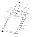
- FIG. 1 is a perspective view showing a schematic configuration of a laminate type battery according to the embodiment.
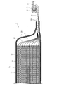
- FIG. 2 is a cross-sectional view taken along line II-II in FIG.
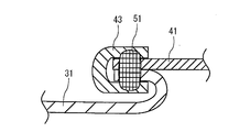
- FIG. 3 is a cross-sectional view showing a bonding structure of the positive electrode connection terminal and the positive electrode wiring.
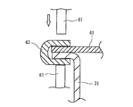
- FIG. 4 is a view showing how the positive electrode connection terminal and the positive electrode wiring are joined by resistance welding.
- FIG. 5 is an enlarged plan view showing the configuration around the bonding portion when the positive electrode connection terminal and the positive electrode wire are bonded at a plurality of places.
- FIG. 1 is a view showing the appearance of a laminate type battery 1 (secondary battery) according to an embodiment of the present invention.
- FIG. 2 is a cross-sectional view showing a schematic configuration of the laminate type battery 1.
- the laminate type battery 1 is a secondary battery in which an electrode body 10 functioning as a power generation body is covered by a laminate film outer package 20.
- the laminate type battery 1 includes an electrode assembly 10 and a laminate film outer package 20 covering the electrode assembly 10.
- the laminate type battery 1 includes a positive electrode connection terminal 31 (terminal) and a negative electrode connection terminal 32 which are connected to the positive electrode 11 and the negative electrode 12 of the electrode body 10 respectively.
- a non-aqueous electrolyte is also enclosed inside the laminate type battery 1.
- the electrode body 10 is a laminate in which the sheet-like positive electrode 11 and the negative electrode 12 are alternately stacked with the separator 13 interposed therebetween.
- the positive electrode 11 is formed by applying a positive electrode mixture containing a positive electrode active material which is a lithium-containing oxide capable of absorbing and releasing lithium ions, a conductive additive, a binder and the like onto a positive electrode current collector made of aluminum foil or the like and drying it. It is formed by Specifically, it is preferable to form a positive electrode active material-containing layer with a thickness of 30 ⁇ m to 300 ⁇ m on an aluminum foil with a thickness of 5 ⁇ m to 60 ⁇ m as the positive electrode 11.
- a positive electrode active material which is a lithium-containing oxide capable of absorbing and releasing lithium ions, a conductive additive, a binder and the like onto a positive electrode current collector made of aluminum foil or the like and drying it. It is formed by Specifically, it is preferable to form a positive electrode active material-containing layer with a thickness of 30 ⁇ m to 300 ⁇ m on an aluminum foil with a thickness of 5 ⁇ m to 60 ⁇ m as the positive electrode 11.
- a lithium-containing oxide which is a positive electrode active material for example, a lithium cobalt oxide such as LiCoO 2 , a lithium manganese oxide such as LiMn 2 O 4 , a lithium composite oxide such as a lithium nickel oxide such as LiNiO 2 is used Is preferred.
- the positive electrode active material only one type of substance may be used, or two or more types of substances may be used. Moreover, a positive electrode active material is not restricted to the thing of the above-mentioned substance. As shown in FIG. 2, the positive electrode current collector of the positive electrode 11 is connected to the positive electrode connection terminal 31 by a positive electrode lead 33.
- the negative electrode 12 is formed by applying and drying a negative electrode mixture containing a negative electrode active material capable of absorbing and releasing lithium ions, a conductive additive, a binder, and the like on a negative electrode current collector made of copper foil or the like. Specifically, it is preferable to form a negative electrode active material-containing layer with a thickness of 30 ⁇ m to 300 ⁇ m on a copper foil with a thickness of 5 ⁇ m to 60 ⁇ m as the negative electrode 12.
- the negative electrode active material for example, it is preferable to use a carbon material (graphites, pyrolytic carbons, cokes, glassy carbons, and the like) capable of inserting and extracting lithium ions.
- a negative electrode active material is not restricted to the thing of the above-mentioned substance.
- the negative electrode 12 is also connected to the negative electrode connection terminal 32 by a negative electrode lead, as in the case of the positive electrode 11. That is, although the structure which connects the positive electrode 11 to the positive electrode connection terminal 31 by the positive electrode lead 33 is shown by FIG. 2, similarly, the negative electrode 12 is also connected to the negative electrode connection terminal 32 by the negative electrode lead which is not shown in figure.
- the positive electrode connection terminal 31 is made of, for example, a foil-like metal material containing aluminum.
- the negative electrode connection terminal 32 is made of, for example, a foil-like metal material containing nickel.
- various surface coatings may be applied to the surfaces of the positive electrode connection terminal 31 and the negative electrode connection terminal 32, respectively, for the plating of different metals and the adhesion improvement with the adhesive layer 31a described later.
- each of the positive electrode connection terminal 31 and the negative electrode connection terminal 32 is sandwiched by the laminate film sheath 20 and integrated with the laminate film sheath 20.
- the other end sides of the positive electrode connection terminal 31 and the negative electrode connection terminal 32 protrude outward of the laminate film outer package 20. That is, as shown in FIG. 1, the positive electrode connection terminal 31 and the negative electrode connection terminal 32 protrude outward in the same direction in the same direction in the laminated film sheath 20 at positions away from each other.
- a positive electrode lead 33 extending from the positive electrode 11 and a negative electrode lead (not shown) extending from the negative electrode 12 are electrically connected to one end of the positive electrode connection terminal 31 and the negative electrode connection terminal 32 integrated with the laminate film sheath 20 respectively. It is done.
- a positive electrode wire 41 (wiring) and a negative electrode wire 42 are connected to the positive electrode connection terminal 31 and the negative electrode connection terminal 32 at tip end portions protruding from the laminate film outer package 20, respectively.
- the positive electrode wire 41 and the negative electrode wire 42 are made of a metal material containing copper.
- the positive electrode connection terminal 31 and the positive electrode wiring 41 are joined by resistance welding.
- the negative electrode connection terminal 32 and the negative electrode wiring 42 are also joined by resistance welding.
- connection terminal 31 made of a metal material containing aluminum and the positive electrode wiring 41 made of a metal material containing copper by resistance welding materials having small volume resistivity are used. It will be joined. Therefore, resistance welding is performed in a state in which the joint portion between the positive electrode connection terminal 31 and the positive electrode wiring 41 is sandwiched by the connection member 43 made of a metal material containing nickel having a large volume resistivity.
- the joint structure including the connection member 43 will be described later.
- the separator 13 is formed of, for example, polyethylene or polypropylene, a fusion of polyethylene and polypropylene, a porous film made of polyethylene terephthalate or polybutylene terephthalate, or a non-woven fabric made of cellulose or the like.
- non-aqueous electrolyte to be enclosed inside the laminate battery 1 examples include lithium carbonate, diethyl carbonate, methyl ethyl carbonate, propylene carbonate, ethylene carbonate, and other organic solvents such as LiPF 6 , LiBF 4 , LiAs 6 , and LiCF 3 SO 3.
- a solution in which a solute such as 3 is dissolved is used.
- a resin or a crosslinking agent may be mixed with this solution and gelled or solidified to be used as a non-aqueous electrolyte.
- the laminated film outer package 20 is made of a material in which one side of an aluminum metal foil is covered with nylon and the other side is covered with polypropylene. That is, the laminate film sheath 20 is made of a material obtained by laminating aluminum with nylon and polypropylene. Thereby, the laminate film sheaths 20 are adhered to each other by applying pressure while heating in a state where the laminate film sheaths 20 are superimposed.
- the metal foil is not limited to aluminum, and may be formed of another metal material such as stainless steel.
- the laminate film outer package 20 is formed in a substantially rectangular shape.
- the outer peripheral side of the laminate film sheath 20 is adhered to each other in a state in which the laminate 10 is enclosed by the laminate film sheath 20, whereby the bulging portion 1a and the seal portion 1b are formed as shown in FIG. 1 and FIG. It is formed. That is, a bulging portion 1a is formed by covering the laminate 10 with the laminate film outer package 20, and the bulging portion 1a is surrounded by bonding the laminate film outer package 20 together on three sides of the bulging portion 1a.
- the seal portion 1 b is formed on the
- adhesive layers 31 a and 32 a are respectively provided between the laminate film outer package 20 and the positive electrode connection terminal 31 and the negative electrode connection terminal 32 partially protruding outward.
- the laminate film outer package 20 can be firmly bonded to the positive electrode connection terminal 31 and the negative electrode connection terminal 32, respectively.
- connection member 43 formed in a substantially U shape. That is, the positive electrode connection terminal 31 and the positive electrode wiring 41 respectively formed in a foil shape are sandwiched by the connection member 43 in a state of being stacked in the thickness direction. Thus, the end portions in the longitudinal direction of the positive electrode connection terminal 31 and the positive electrode wire 41 are covered by the connection member 43.
- the positive electrode connection terminal 31 and the positive electrode wiring 41 are joined by resistance welding in the laminating direction in a state of being sandwiched by the connection member 43. That is, as illustrated in an enlarged manner in FIG. 3, the positive electrode connection terminal 31, the positive electrode wiring 41, and the connection member 43 are provided with the bonding portion 51 so as to extend in the overlapping direction (stacking direction).
- the joint portion 51 is formed by passing a current to the electrode rod 61 while sandwiching the positive electrode connection terminal 31, the positive electrode wiring 41 and the connection member 43 by a pair of electrode rods 61 of a welding device. Be done.
- the connection member 43 is made of, for example, a material such as nickel having a volume resistivity larger than that of the positive electrode connection terminal 31 and the positive electrode wiring 41.
- the volume resistivity of the positive electrode connection terminal 31 made of a metal material containing aluminum is 0.028 ⁇ ⁇ m
- the volume resistivity of the positive electrode wiring 41 made of a metal material containing copper is 0.015 ⁇ ⁇
- the volume resistivity of the connection member 43 is, for example, 0.069 ⁇ ⁇ m.
- connection member 43 As described above, when resistance welding is performed in a state where the positive electrode connection terminal 31 and the positive electrode wiring 41 are sandwiched by the connection member 43 having a relatively large volume resistivity, sufficient heat generation can be obtained in the connection member 43. As a result, the positive electrode connection terminal 31, the positive electrode wiring 41, and the connection member 43 are sufficiently melted to form the bonding portion 51.
- the bonding portion 51 is made of an alloy layer containing nickel. Therefore, sufficient bonding strength can be obtained at the bonding portion 51.
- a peeling strength test was performed using a test body in which one point is bonded by resistance welding in a state in which the positive electrode connecting terminal 31 and the positive electrode wiring 41 are sandwiched by the connecting members 43. .
- a positive electrode connection terminal of 7 mm in width and 0.1 mm in thickness and a positive electrode wiring of 3 mm in width and 0.1 mm in thickness are sandwiched by connecting members of 3 mm in width and 0.1 mm in thickness, while pressing with 25 N
- Ten specimens were fabricated by resistance welding at a current of 2.4 kA for 1.4 mS.
- the positive electrode connection terminal and the positive electrode wiring were peeled off in the direction of 180 degrees, respectively, and the peel strength of the bonding portion was determined.
- the peel strength of the joint was about 12.5N. In the configuration of the present embodiment, since it has a peeling strength of 10 N or more, it was found that the strength against falling or the like is sufficient.
- the positive electrode connection terminal 31 and the positive electrode wire 41 are in direct electrical contact. Therefore, when charging and discharging the battery, current flows in the positive electrode connection terminal 31 and the positive electrode wiring 41 without passing through the connection member 43. Therefore, current can flow to the positive electrode connection terminal 31 and the positive electrode wiring 41 having a relatively small volume resistivity, so that the resistance of the battery can be reduced.
- the resistance of positive electrode connection terminal 31 and positive electrode wiring 41 can be reduced, and positive electrode connection terminal 31 and positive electrode wiring 41 can be joined by inexpensive resistance welding such that sufficient bonding strength can be obtained. it can.
- a plurality of bonding portions 51 for bonding the positive electrode connection terminal 31, the positive electrode wire 41 and the connection member 43 may be provided (four in the example of FIG. 5).
- the joint strength of the positive electrode connection terminal 31, the positive electrode wiring 41, and the connection member 43 can be improved by providing the joint portions 51 at a plurality of places.
- the positive electrode connection terminal 31 and the positive electrode wire 41 can be joined with sufficient bonding strength by inexpensive resistance welding while reducing the resistance of the positive electrode connection terminal 31 and the positive electrode wire 41. Therefore, it is possible to prevent the increase in the manufacturing cost of the battery while reducing the resistance of the battery.
- the said embodiment demonstrated the structure of the laminate type battery 1 which covered the electrode body 10 by the laminate film exterior body 20.
- FIG. However, other types of batteries may be used as long as they can be charged and discharged.
- the positive electrode connection terminal 31 is made of a metal material containing aluminum
- the positive electrode wiring 41 is made of a metal material containing copper.
- the positive electrode connection terminal and the positive electrode wiring may be made of any metal material.
- connection member 43 is made of a metallic material containing nickel.
- the connecting member may be made of any metal material as long as the metal material is larger in volume resistivity than the positive electrode connection terminal and the positive electrode wiring.
- the positive electrode connection terminal 31 and the positive electrode wire 41 are sandwiched by the connection member 43 and joined by resistance welding.
- the negative electrode connection terminal 32 and the negative electrode wire 42 may be sandwiched by the connection member 43 and joined by resistance welding.
- the electrode body 10 is comprised by laminating
- the electrode body may have any configuration, such as a configuration in which a positive electrode, a negative electrode, and a separator, each formed in a strip shape, are wound.
- the positive electrode connection terminal 31 and the negative electrode connection terminal 32 are connected to the electrode body 10 one by one.
- a plurality of positive electrode connection terminals 31 and a plurality of negative electrode connection terminals 32 may be connected to the electrode body 10.
- the laminate type battery 1 is a lithium ion battery.
- the laminate type battery 1 may be a battery other than a lithium ion battery.
- the present invention is applicable to a secondary battery in which a terminal and a wire extending outward from an electrode body are connected.
Landscapes
- Chemical & Material Sciences (AREA)
- Chemical Kinetics & Catalysis (AREA)
- Electrochemistry (AREA)
- General Chemical & Material Sciences (AREA)
- Engineering & Computer Science (AREA)
- Manufacturing & Machinery (AREA)
- Mechanical Engineering (AREA)
- Connection Of Batteries Or Terminals (AREA)
Abstract
ラミネート形電池(1)は、電極体と(10)、正極接続端子(31)と、正極接続端子(31)に電気的に接続される正極配線(41)と、正極接続端子(31)と正極配線(41)との接続部分に配置される接続部材(43)とを備える。接続部材(43)は、正極接続端子(31)及び正極配線(41)よりも体積抵抗率の大きい材料によって構成されている。接続部材(43)、正極接続端子(31)及び正極配線(41)は、接続部材(43)が正極接続端子(31)及び正極配線(41)を挟み込んだ状態で、それらの積層方向に抵抗溶接によって互いに接合されている。
Description
本発明は、電極体から外方に向かって延びる端子を有し、該端子に配線が接続される二次電池に関する。
従来より、電極体から外方に向かって延びる端子を有し、該端子に配線が接続される二次電池が知られている。このような二次電池では、例えば特開2000-90907号公報および特開2000-90906号公報に開示されるように、異なる種類の金属材料からなる端子及び配線が接合される。
特開2000-90907号公報の構成では、箔状のアルミニウムからなる正極リードを、リン青銅からなる正極接続リードによって挟み込み、それらが重ね合わされている位置でスポット溶接されている。
一方、特開2000-90906号公報の構成では、箔状のアルミニウムからなる正極リードとリン青銅からなる外部出力端子とが、アルミニウムとリン青銅とを圧延及び接合してなるクラッド材により形成された正極接続リードを介して、スポット溶接されている。
特開2000-90907号公報および特開2000-90906号公報のように抵抗溶接を用いて異種金属同士を接合する場合、体積抵抗率の小さい材料では、接合部分で材料が十分に溶融しないため、十分な接合強度を確保できない可能性がある。したがって、抵抗溶接を用いて異種金属同士を接合する場合には、一方の部材に体積抵抗率が比較的大きい金属材料を用いるのが一般的である。
ところで、近年、携帯端末等の普及により、電池容量の大型化が要求されているとともに、電池の充電時間の短縮も要求されている。このように電池容量を増加させつつ、充電時間を短縮するためには、急速充電によって電池を効率良く充電する必要がある。
電池を充電する場合、定電流で充電(定電流充電)して電池の電圧が所定値に達した後に、定電圧で充電(定電圧充電)するのが一般的である。定電流充電の際に、電池の抵抗が大きいと、その分、電池に印加される電圧が大きくなる。そうすると、定電流充電が十分な時間、行われることなく、電池の電圧が短時間で所定値に達する。この場合、定電流充電によって十分な充電量が得られず、電池の充電時間が長くなる。
そのため、効率良く急速充電を行うためには、電池の抵抗をできるだけ小さくする必要がある。したがって、電極体から外方に向かって延びる端子及び該端子に接続される配線も、できるだけ体積抵抗率の小さい金属材料を用いる必要がある。
このように、端子及び配線に体積抵抗率の小さい金属材料を用いた場合、上述のように、抵抗溶接によって十分に材料を溶融させることができず、接合強度の低下を招くおそれがある。なお、部材同士を接合する方法としては、抵抗溶接以外にも、レーザー溶接や超音波溶接などの溶接方法もあるが、いずれの方法も高価な装置を必要とする。そのため、部材同士を接合する際は、より廉価な装置によって接合可能な抵抗溶接を用いるのが好ましい。
本発明の目的は、電極体から外方に向かって延びる端子に配線が接続される二次電池において、端子及び配線の抵抗を低減しつつ、端子と配線とを抵抗溶接によってより確実に接合可能な構成を得ることにある。
本発明の一実施形態に係る二次電池は、充放電可能な電極体と、電極体から外方に向かって延びる端子と、端子に電気的に接続される配線と、端子と配線との接続部分に配置される接続部材とを備える。接続部材は、端子及び配線よりも体積抵抗率の大きい材料によって構成されていて、端子の端部と配線の端部とを重ね合わせた状態で、端子の端部と配線の端部とを挟み込むように配置されている。接続部材、端子及び配線は、接続部材が端子及び配線を挟み込んだ状態で、重なる方向に抵抗溶接によって互いに接合されている(第1の構成)。
これにより、端子及び配線を体積抵抗率の小さい金属材料によって構成しつつ、接続部材を端子及び配線よりも体積抵抗率の大きい金属材料によって構成して、接続部材を用いて端子及び配線を接合することが可能になる。すなわち、端子と配線とは直接、電気的に接続されるため、電池の充放電の際に、接続部材には電流が流れない。よって、接続部材を端子及び配線よりも体積抵抗率の大きい金属材料によって構成することで、接続部材によって挟み込まれた端子及び配線を抵抗溶接によって接合することができる。しかも、電池の充放電の際には、電流は体積抵抗率の小さい端子及び配線に流れるため、電池の抵抗を低減することができる。
したがって、上述の構成により、電池の抵抗を低減しつつ、抵抗溶接によって端子と配線とを十分な接合強度で接合することができる。
第1の構成において、接続部材は、端子の端部と配線の端部とを重ね合わせた状態で端子の端部と配線の端部とを挟み込むようにU字状に形成されている(第2の構成)。これにより、端子の端部と配線の端部とを、重ね合わせた状態で接続部材によってより確実に挟み込むことができる。
第1または第2の構成において、接続部材、端子及び配線は、抵抗溶接によって複数個所で互いに接合されている(第3の構成)。これにより、接続部材、端子及び配線を、より確実に接合することができる。すなわち、抵抗溶接による接合箇所の数が増えるほど、接合強度は高くなる。よって、接続部材、端子及び配線を抵抗溶接によって複数個所で接合することにより、それらの部材をより強固に接合することができる。
第1から第3の構成のうちいずれか一つの構成において、配線は、少なくとも銅を含む金属材料によって構成されていて、接続部材、端子及び配線は、少なくとも銅を含む金属材料によって構成された電極棒を用いて抵抗溶接によって互いに接合される(第4の構成)。
配線に体積抵抗率が小さい銅を用いることにより、配線の抵抗を低減することができる。これにより、電池の抵抗を低減することができ、電池の急速充電を効率良く行うことができる。
しかも、抵抗溶接に用いる電極棒を比較的廉価な銅によって構成した場合でも、銅製の配線は、電極棒と直接、接触しないため、電極棒に付着しない。これにより、銅製の配線を、端子とともに体積抵抗率の高い金属材料からなる接続部材によって挟み込んだ状態で抵抗溶接によって端子と接合することができる。これにより、抵抗溶接時に配線が電極棒に付着するのを防止することができる。
したがって、上述の構成により、より廉価な溶接装置を用いて、電池の端子と配線とを十分な接合強度で接合することができる。
第1から第4の構成のうちいずれか一つの構成において、接続部材は、少なくともニッケルを含む金属材料によって構成されていて、端子及び配線は、ニッケルよりも体積抵抗率の小さい材料によって構成されている(第5の構成)。
これにより、端子及び配線を接続部材によって挟み込んだ状態で、それらの部材を抵抗溶接によって十分な接合強度で接合することができる。すなわち、上述の構成により、端子及び配線の抵抗を低減しつつ、端子及び配線を抵抗溶接によって十分な接合強度で接合可能な構成を実現できる。
本発明の一実施形態に係る二次電池によれば、電極体から外方に向かって延びる端子と配線とを、互いに重ね合わせた状態でそれらよりも体積抵抗率の大きい接続部材によって挟み込んで、接続部材、端子及び配線を抵抗溶接によって接合する。これにより、端子及び配線に体積抵抗率の小さい金属材料を用いつつ、端子と配線とを抵抗溶接によって十分な接合強度で接合することができる。したがって、電池の抵抗の低減を図りつつ、端子と配線とを低コストな溶接方法でより確実に接合することができる。
以下、図面を参照し、本発明の実施の形態を詳しく説明する。なお、各図中の構成部材の寸法は、実際の構成部材の寸法及び各構成部材の寸法比率等を忠実に表したものではない。
(全体構成)
図1は、本発明の一実施形態であるラミネート形電池1(二次電池)の外観を示す図である。図2は、ラミネート形電池1の概略構成を示す断面図である。このラミネート形電池1は、発電体として機能する電極体10がラミネートフィルム外装体20によって覆われた二次電池である。
図1は、本発明の一実施形態であるラミネート形電池1(二次電池)の外観を示す図である。図2は、ラミネート形電池1の概略構成を示す断面図である。このラミネート形電池1は、発電体として機能する電極体10がラミネートフィルム外装体20によって覆われた二次電池である。
図1及び図2に示すように、ラミネート形電池1は、電極体10と、該電極体10を覆うラミネートフィルム外装体20とを備える。また、ラミネート形電池1は、電極体10の正極11及び負極12にそれぞれ接続される正極接続端子31(端子)及び負極接続端子32を備える。なお、ラミネート形電池1の内部には、非水電解質も封入されている。
電極体10は、シート状の正極11及び負極12がセパレータ13を間に挟んで交互に積層された積層体である。
正極11は、リチウムイオンを吸蔵・放出可能なリチウム含有酸化物である正極活物質、導電助剤及びバインダなどを含む正極合剤を、アルミニウム箔などからなる正極集電体上に塗布して乾燥させることによって形成される。具体的には、正極11として、5μmから60μmの厚みのアルミニウム箔上に、30μmから300μmの厚みの正極活物質含有層を形成するのが好ましい。正極活物質であるリチウム含有酸化物としては、例えば、LiCoO2などのリチウムコバルト酸化物やLiMn2O4などのリチウムマンガン酸化物、LiNiO2などのリチウムニッケル酸化物等のリチウム複合酸化物を用いるのが好ましい。なお、正極活物質として、1種類の物質のみを用いてもよいし、2種類以上の物質を用いてもよい。また、正極活物質は、上述の物質のものに限られない。図2に示すように、正極11の正極集電体は、正極リード33によって正極接続端子31に接続されている。
負極12は、リチウムイオンを吸蔵・放出可能な負極活物質、導電助剤及びバインダなどを含む負極合剤を、銅箔などからなる負極集電体上に塗布して乾燥させることによって形成される。具体的には、負極12として、5μmから60μmの厚みの銅箔に、30μmから300μmの厚みの負極活物質含有層を形成するのが好ましい。負極活物質としては、例えば、リチウムイオンを吸蔵・放出可能な炭素材料(黒鉛類、熱分解炭素類、コークス類、ガラス状炭素類など)を用いるのが好ましい。なお、負極活物質は、上述の物質のものに限られない。特に図示しないが、負極12も、正極11と同様、負極リードによって負極接続端子32に接続されている。すなわち、図2には、正極11を正極リード33によって正極接続端子31に接続する構成が示されているが、同様に、負極12も図示しない負極リードによって負極接続端子32に接続されている。
正極接続端子31は、例えばアルミニウムを含む箔状の金属材料によって構成される。一方、負極接続端子32は、例えばニッケルを含む箔状の金属材料によって構成される。なお、正極接続端子31及び負極接続端子32の表面には、それぞれ、異種金属のメッキや、後述する接着層31aとの接着性向上のために各種表面コーティングが施されていてもよい。
図2に示すように、正極接続端子31及び負極接続端子32は、それぞれ、一端側がラミネートフィルム外装体20によって挟み込まれて該ラミネートフィルム外装体20と一体化される。一方、正極接続端子31及び負極接続端子32の他端側は、ラミネートフィルム外装体20の外方に向かって突出している。すなわち、図1に示すように、正極接続端子31及び負極接続端子32は、互いに離間した位置で、ラミネートフィルム外装体20の外方へ同じ方向に向かって突出している。正極接続端子31及び負極接続端子32においてラミネートフィルム外装体20と一体化された一端側には、それぞれ、正極11から延びる正極リード33及び負極12から延びる負極リード(図示省略)が電気的に接続されている。
正極接続端子31及び負極接続端子32には、それぞれ、ラミネートフィルム外装体20から突出した先端部分に正極配線41(配線)及び負極配線42が接続されている。正極配線41及び負極配線42は、銅を含む金属材料によって構成されている。正極接続端子31及び正極配線41は、抵抗溶接によって接合されている。負極接続端子32及び負極配線42も、抵抗溶接によって接合されている。
詳しくは後述するが、アルミニウムを含む金属材料によって構成される正極接続端子31と銅を含む金属材料によって構成される正極配線41とを、抵抗溶接によって溶接する場合、体積抵抗率の小さい材料同士を接合することになる。そのため、正極接続端子31と正極配線41との接合部分を、体積抵抗率の大きいニッケルを含む金属材料からなる接続部材43によって挟み込んだ状態で抵抗溶接を行う。接続部材43を含めた接合構造については後述する。
セパレータ13は、例えば、ポリエチレンやポリプロピレン、ポリエチレンとポリプロピレンとの融合体、ポリエチレンテレフタレートやポリブチレンテレフタレートなどによって構成された多孔質フィルム、または、セルロースなどからなる不織布によって形成される。
ラミネート外装型電池1の内部に封入される非水電解質としては、ジメチルカーボネートやジエチルカーボネート、メチルエチルカーボネート、プロピレンカーボネート、エチレンカーボネートなどの有機溶媒に、LiPF6、LiBF4、LiAs6、LiCF3SO3などの溶質を溶解させた溶液が用いられる。また、この溶液に、樹脂や架橋剤を混合してゲル状化または固形化させたものを非水電解質として用いてもよい。
ラミネートフィルム外装体20は、アルミニウム製の金属箔の一面側がナイロンで覆われ、且つ、他面側がポリプロピレンで覆われた材料からなる。すなわち、ラミネートフィルム外装体20は、アルミニウムをナイロン及びポリプロピレンでラミネートした材料からなる。これにより、ラミネートフィルム外装体20は、ラミネートフィルム外装体20同士を重ね合わせた状態で加熱しながら圧力を加えることによって、互いに接着される。なお、金属箔は、アルミニウムに限らず、ステンレス等の他の金属材料によって形成してもよい。
ラミネートフィルム外装体20は、略長方形状に形成されている。このラミネートフィルム外装体20によって積層体10を包み込んだ状態で、該ラミネートフィルム外装体20の外周側同士を接着することにより、図1及び図2に示すように膨出部1a及びシール部1bが形成される。すなわち、ラミネートフィルム外装体20が積層体10を覆うことにより膨出部1aが形成され、該膨出部1aの三方でラミネートフィルム外装体20同士を接着することにより該膨出部1aを囲むようにシール部1bが形成される。
ここで、ラミネートフィルム外装体20と、その外方に一部が突出する正極接続端子31及び負極接続端子32との間には、それぞれ、接着層31a,32aが設けられている。これらの接着層31a,32aを設けることにより、ラミネートフィルム外装体20と正極接続端子31及び負極接続端子32とをそれぞれ強固に接着することができる。
(接合構造)
次に、正極接続端子31と正極配線41との接合構造について図2から図4を用いて詳細に説明する。
次に、正極接続端子31と正極配線41との接合構造について図2から図4を用いて詳細に説明する。
ラミネートフィルム外装体20から一端側が突出した正極接続端子31の先端部分は、正極配線41の一端側とともに、略U字状に形成された接続部材43によって挟み込まれている。すなわち、それぞれ箔状に形成された正極接続端子31及び正極配線41は、厚み方向に積層された状態で接続部材43によって挟み込まれている。これにより、正極接続端子31及び正極配線41の長手方向の端部は接続部材43によって覆われている。
正極接続端子31及び正極配線41は、接続部材43によって挟み込まれた状態で、それらの積層方向に抵抗溶接によって接合されている。すなわち、図3に拡大して図示するように、正極接続端子31、正極配線41及び接続部材43には、それらが重なる方向(積層方向)に延びるように接合部51が形成されている。
接合部51は、図4に示すように、溶接装置の一対の電極棒61によって正極接続端子31、正極配線41及び接続部材43を挟み込んだ状態で、該電極棒61に電流を流すことにより形成される。
接続部材43は、例えばニッケルなど、正極接続端子31及び正極配線41よりも体積抵抗率の大きい材料によって構成されている。具体的には、アルミニウムを含む金属材料によって構成される正極接続端子31の体積抵抗率は0.028μΩ・m、銅を含む金属材料によって構成される正極配線41の体積抵抗率は0.015μΩ・mであるのに対し、接続部材43の体積抵抗率は例えば0.069μΩ・mである。
上述のように、比較的、体積抵抗率の大きい接続部材43によって正極接続端子31及び正極配線41を挟み込んだ状態で抵抗溶接する際には、接続部材43において十分な発熱が得られる。その結果、正極接続端子31、正極配線41及び接続部材43が十分に溶融して、接合部51が形成される。接合部51は、ニッケルを含む合金層からなる。したがって、接合部51で十分な接合強度が得られる。
接合部51の接合強度を確認するために、正極接続端子31及び正極配線41を接続部材43によって挟み込んだ状態で抵抗溶接によって1点が接合された試験体を用いて、剥離強度試験を行った。幅7mm、厚さ0.1mmの正極接続端子と、幅3mm、厚さ0.1mmの正極配線とを、幅3mm、厚さ0.1mmの接続部材によって挟み込んだ状態で、25Nで加圧しながら電流2.4kAを1.4mSの間、流して抵抗溶接することにより、10個の試験体を製作した。そして、正極接続端子と正極配線とをそれぞれ180度方向に引きはがし、接合部の剥離強度を求めた。10個の試験体の試験結果を平均すると、接合部の剥離強度は約12.5Nであった。本実施形態の構成では、10N以上の剥離強度を有するため、落下等に対する強度は十分であることが分かった。
よって、本実施形態の構成では、抵抗溶接によって形成される接合部51で十分な接合強度が得られる。
また、上述のように、接続部材43によって正極接続端子31及び正極配線41を挟み込むことにより、正極接続端子31と正極配線41とが直接、電気的に接触する。これにより、電池の充放電を行う際に接続部材43を介さずに正極接続端子31及び正極配線41に電流が流れる。したがって、比較的、体積抵抗率の小さい正極接続端子31及び正極配線41に電流を流すことができるため、電池の抵抗を低減することができる。
したがって、以上の構成により、正極接続端子31及び正極配線41の抵抗を低減しつつ、正極接続端子31と正極配線41とを廉価な抵抗溶接によって十分な接合強度が得られるように接合することができる。
なお、図5に示すように、正極接続端子31、正極配線41及び接続部材43を接合する接合部51を複数個所(図5の例では4箇所)、設けてもよい。このように、接合部51を複数個所、設けることにより、正極接続端子31、正極配線41及び接続部材43の接合強度を向上することができる。
(実施形態の効果)
以上より、この実施形態では、正極接続端子31及び正極配線41の端部を重ね合わせた状態で、それらよりも体積抵抗率の大きい略U字状の接続部材43によって挟み込む。その状態で、抵抗溶接によって、正極接続端子31、正極配線41及び接続部材43を接合する。これにより、正極接続端子31及び正極配線41を体積抵抗率の小さい材料によって構成した場合でも、抵抗溶接によって十分な接合強度が得られる。しかも、正極接続端子31と正極配線41とは直接、電気的に接触するため、体積抵抗率の大きい接続部材43には電流は流れない。
以上より、この実施形態では、正極接続端子31及び正極配線41の端部を重ね合わせた状態で、それらよりも体積抵抗率の大きい略U字状の接続部材43によって挟み込む。その状態で、抵抗溶接によって、正極接続端子31、正極配線41及び接続部材43を接合する。これにより、正極接続端子31及び正極配線41を体積抵抗率の小さい材料によって構成した場合でも、抵抗溶接によって十分な接合強度が得られる。しかも、正極接続端子31と正極配線41とは直接、電気的に接触するため、体積抵抗率の大きい接続部材43には電流は流れない。
したがって、上述の構成により、正極接続端子31及び正極配線41の抵抗を低減しつつ、廉価な抵抗溶接によって、正極接続端子31と正極配線41とを十分な接合強度で接合することができる。よって、電池の抵抗を低減しつつ、電池の製造コストの増加を防止することができる。
(その他の実施形態)
以上、本発明の実施の形態を説明したが、上述した実施の形態は本発明を実施するための例示に過ぎない。よって、上述した実施の形態に限定されることなく、その趣旨を逸脱しない範囲内で上述した実施の形態を適宜変形して実施することが可能である。
以上、本発明の実施の形態を説明したが、上述した実施の形態は本発明を実施するための例示に過ぎない。よって、上述した実施の形態に限定されることなく、その趣旨を逸脱しない範囲内で上述した実施の形態を適宜変形して実施することが可能である。
前記実施形態では、電極体10をラミネートフィルム外装体20によって覆ったラミネート形電池1の構成について説明した。しかしながら、充放電可能な二次電池であれば、他のタイプの電池であってもよい。
前記実施形態では、正極接続端子31はアルミニウムを含む金属材料によって構成されていて、正極配線41は銅を含む金属材料によって構成されている。しかしながら、リチウムよりも体積抵抗率の小さい金属材料であれば、正極接続端子及び正極配線はどのような金属材料によって構成されていてもよい。
前記実施形態では、接続部材43はニッケルを含む金属材料によって構成されている。しかしながら、正極接続端子及び正極配線よりも体積抵抗率の大きい金属材料であれば、接続部材はどのような金属材料によって構成されていてもよい。
前記実施形態では、正極接続端子31と正極配線41とを接続するために、接続部材43によって正極接続端子31及び正極配線41を挟み込んだ状態で抵抗溶接によって接合している。しかしながら、負極接続端子32と負極配線42とを接続するために、接続部材43によって負極接続端子32及び負極配線42を挟み込んだ状態で抵抗溶接によって接合してもよい。
前記実施形態では、それぞれシート状に形成された正極11、負極12及びセパレータ13を積層することによって、電極体10を構成する。しかしながら、電極体は、それぞれ帯状に形成された正極、負極及びセパレータを巻回した構成など、どのような構成であってもよい。
前記実施形態では、電極体10に正極接続端子31及び負極接続端子32が一つずつ接続されている。しかしながら、電極体10に、正極接続端子31及び負極接続端子32をそれぞれ複数、接続してもよい。
前記実施形態では、ラミネート形電池1はリチウムイオン電池である。しかしながら、ラミネート形電池1はリチウムイオン電池以外の電池であってもよい。
本発明は、電極体から外方に向かって延びる端子と配線とが接続される二次電池に利用可能である。
Claims (5)
- 充放電可能な電極体と、
前記電極体から外方に向かって延びる端子と、
前記端子に電気的に接続される配線と、
前記端子と前記配線との接続部分に配置される接続部材とを備え、
前記接続部材は、前記端子及び前記配線よりも体積抵抗率の大きい材料によって構成されていて、前記端子の端部と前記配線の端部とを重ね合わせた状態で、前記端子の端部と前記配線の端部とを挟み込むように配置され、
前記接続部材、前記端子及び前記配線は、前記接続部材が前記端子及び前記配線を挟み込んだ状態で、重なる方向に抵抗溶接によって互いに接合されている、二次電池。 - 請求項1に記載の二次電池において、
前記接続部材は、前記端子の端部と前記配線の端部とを重ね合わせた状態で前記端子の端部と前記配線の端部とを挟み込むようにU字状に形成されている、二次電池。 - 請求項1または2に記載の二次電池において、
前記接続部材、前記端子及び前記配線は、抵抗溶接によって複数個所で互いに接合されている、二次電池。 - 請求項1から3のいずれか一つに記載の二次電池において、
前記配線は、少なくとも銅を含む金属材料によって構成されていて、
前記接続部材、前記端子及び前記配線は、少なくとも銅を含む金属材料によって構成された電極棒を用いて抵抗溶接によって互いに接合される、二次電池。 - 請求項1から4のいずれか一つに記載の二次電池において、
前記接続部材は、少なくともニッケルを含む金属材料によって構成されていて、
前記端子及び前記配線は、ニッケルよりも体積抵抗率の小さい材料によって構成されている、二次電池。
Applications Claiming Priority (2)
| Application Number | Priority Date | Filing Date | Title |
|---|---|---|---|
| JP2013004714A JP6077312B2 (ja) | 2013-01-15 | 2013-01-15 | 二次電池 |
| JP2013-004714 | 2013-01-15 |
Publications (1)
| Publication Number | Publication Date |
|---|---|
| WO2014112296A1 true WO2014112296A1 (ja) | 2014-07-24 |
Family
ID=51209398
Family Applications (1)
| Application Number | Title | Priority Date | Filing Date |
|---|---|---|---|
| PCT/JP2013/084334 Ceased WO2014112296A1 (ja) | 2013-01-15 | 2013-12-20 | 二次電池 |
Country Status (2)
| Country | Link |
|---|---|
| JP (1) | JP6077312B2 (ja) |
| WO (1) | WO2014112296A1 (ja) |
Families Citing this family (2)
| Publication number | Priority date | Publication date | Assignee | Title |
|---|---|---|---|---|
| JP2017010856A (ja) * | 2015-06-24 | 2017-01-12 | 日立マクセル株式会社 | ラミネート形電池 |
| JP7668520B2 (ja) * | 2021-03-19 | 2025-04-25 | ナグシステム株式会社 | 抵抗溶接方法および抵抗溶接装置 |
Citations (8)
| Publication number | Priority date | Publication date | Assignee | Title |
|---|---|---|---|---|
| US3036200A (en) * | 1958-01-17 | 1962-05-22 | Atomic Energy Authority Uk | Resistance welding |
| US3277268A (en) * | 1964-10-12 | 1966-10-04 | Thomas Richard & Baldwins Ltd | Welding of coated sheet or strip |
| JPH10146679A (ja) * | 1996-11-13 | 1998-06-02 | Denso Corp | 異種材料の電気抵抗溶接方法 |
| JP2000090907A (ja) * | 1998-09-11 | 2000-03-31 | Matsushita Electric Ind Co Ltd | リード接合構造及びこの構造を用いた電池パック |
| JP2000243374A (ja) * | 1999-02-16 | 2000-09-08 | Hitachi Maxell Ltd | ポリマー電解質電池 |
| JP2002141051A (ja) * | 2000-11-01 | 2002-05-17 | Sony Corp | 電池およびその製造方法 |
| JP2003187778A (ja) * | 2001-12-21 | 2003-07-04 | Japan Storage Battery Co Ltd | 電 池 |
| JP2011204439A (ja) * | 2010-03-25 | 2011-10-13 | Furukawa Battery Co Ltd:The | 組電池、抵抗溶接方法および組電池の製造方法 |
Family Cites Families (4)
| Publication number | Priority date | Publication date | Assignee | Title |
|---|---|---|---|---|
| JPS52112768A (en) * | 1976-03-18 | 1977-09-21 | Showa Musen Kougiyou Kk | Method of connecting flexible conductor |
| JP2002016336A (ja) * | 2000-06-28 | 2002-01-18 | Japan Aviation Electronics Industry Ltd | 電気的接続構造及びその形成用治具 |
| JP2002289279A (ja) * | 2001-03-22 | 2002-10-04 | Sumitomo Wiring Syst Ltd | 接続クリップ |
| JP2004172295A (ja) * | 2002-11-19 | 2004-06-17 | Sony Corp | 回路基板及び電池ユニット |
-
2013
- 2013-01-15 JP JP2013004714A patent/JP6077312B2/ja active Active
- 2013-12-20 WO PCT/JP2013/084334 patent/WO2014112296A1/ja not_active Ceased
Patent Citations (8)
| Publication number | Priority date | Publication date | Assignee | Title |
|---|---|---|---|---|
| US3036200A (en) * | 1958-01-17 | 1962-05-22 | Atomic Energy Authority Uk | Resistance welding |
| US3277268A (en) * | 1964-10-12 | 1966-10-04 | Thomas Richard & Baldwins Ltd | Welding of coated sheet or strip |
| JPH10146679A (ja) * | 1996-11-13 | 1998-06-02 | Denso Corp | 異種材料の電気抵抗溶接方法 |
| JP2000090907A (ja) * | 1998-09-11 | 2000-03-31 | Matsushita Electric Ind Co Ltd | リード接合構造及びこの構造を用いた電池パック |
| JP2000243374A (ja) * | 1999-02-16 | 2000-09-08 | Hitachi Maxell Ltd | ポリマー電解質電池 |
| JP2002141051A (ja) * | 2000-11-01 | 2002-05-17 | Sony Corp | 電池およびその製造方法 |
| JP2003187778A (ja) * | 2001-12-21 | 2003-07-04 | Japan Storage Battery Co Ltd | 電 池 |
| JP2011204439A (ja) * | 2010-03-25 | 2011-10-13 | Furukawa Battery Co Ltd:The | 組電池、抵抗溶接方法および組電池の製造方法 |
Also Published As
| Publication number | Publication date |
|---|---|
| JP6077312B2 (ja) | 2017-02-08 |
| JP2014137862A (ja) | 2014-07-28 |
Similar Documents
| Publication | Publication Date | Title |
|---|---|---|
| JP7054892B2 (ja) | 組電池及び組電池の製造方法 | |
| JP4135473B2 (ja) | バイポーラ電池 | |
| CN105576281B (zh) | 非水电解质二次电池及其制造方法 | |
| KR101797338B1 (ko) | 2차 전지 | |
| JP2009087611A (ja) | 積層式電池 | |
| WO2014034241A1 (ja) | 角形二次電池 | |
| JP4655593B2 (ja) | バイポーラ電池 | |
| JP5678270B2 (ja) | 発電要素および二次電池 | |
| WO2010134170A1 (ja) | 積層型二次電池および積層型二次電池の製造方法 | |
| JP2010086780A (ja) | 角形二次電池 | |
| KR20190037110A (ko) | 전기 화학 소자 | |
| JP4042613B2 (ja) | バイポーラ電池 | |
| JP4670275B2 (ja) | バイポーラ電池および組電池 | |
| JP4218400B2 (ja) | バイポーラ電池、バイポーラ電池の製造方法、組電池および車両 | |
| JP2005129344A (ja) | 二次電池、組電池、複合組電池、車輌、及び、二次電池の製造方法 | |
| JP2019029642A (ja) | 電気化学セルモジュール及び電気化学セルモジュールの製造方法 | |
| JP6682203B2 (ja) | 二次電池の製造方法 | |
| JP6077312B2 (ja) | 二次電池 | |
| JP2012164476A (ja) | ラミネート形電池およびそれを備えた積層型電池 | |
| CN116711044A (zh) | 蓄电单元和蓄电装置 | |
| JP2002134094A (ja) | 密閉型電池 | |
| JP2011216205A (ja) | ラミネート形電池およびその製造方法 | |
| JP2006156000A (ja) | バイポーラ電池およびその製造方法、組電池、自動車 | |
| WO2023189249A1 (ja) | 蓄電装置 | |
| JP4367220B2 (ja) | バイポーラ電池、バイポーラ電池の製造方法、組電池、およびこの組電池を用いた自動車 |
Legal Events
| Date | Code | Title | Description |
|---|---|---|---|
| 121 | Ep: the epo has been informed by wipo that ep was designated in this application |
Ref document number: 13872004 Country of ref document: EP Kind code of ref document: A1 |
|
| NENP | Non-entry into the national phase |
Ref country code: DE |
|
| 122 | Ep: pct application non-entry in european phase |
Ref document number: 13872004 Country of ref document: EP Kind code of ref document: A1 |