WO2014098172A1 - 加工装置の制御装置、加工装置、加工装置の制御プログラム、加工装置の制御方法、及び加工方法 - Google Patents
加工装置の制御装置、加工装置、加工装置の制御プログラム、加工装置の制御方法、及び加工方法 Download PDFInfo
- Publication number
- WO2014098172A1 WO2014098172A1 PCT/JP2013/084027 JP2013084027W WO2014098172A1 WO 2014098172 A1 WO2014098172 A1 WO 2014098172A1 JP 2013084027 W JP2013084027 W JP 2013084027W WO 2014098172 A1 WO2014098172 A1 WO 2014098172A1
- Authority
- WO
- WIPO (PCT)
- Prior art keywords
- processing
- phase difference
- vibration
- rotations
- workpiece
- Prior art date
- Legal status (The legal status is an assumption and is not a legal conclusion. Google has not performed a legal analysis and makes no representation as to the accuracy of the status listed.)
- Ceased
Links
Images

Classifications
-
- B—PERFORMING OPERATIONS; TRANSPORTING
- B23—MACHINE TOOLS; METAL-WORKING NOT OTHERWISE PROVIDED FOR
- B23Q—DETAILS, COMPONENTS, OR ACCESSORIES FOR MACHINE TOOLS, e.g. ARRANGEMENTS FOR COPYING OR CONTROLLING; MACHINE TOOLS IN GENERAL CHARACTERISED BY THE CONSTRUCTION OF PARTICULAR DETAILS OR COMPONENTS; COMBINATIONS OR ASSOCIATIONS OF METAL-WORKING MACHINES, NOT DIRECTED TO A PARTICULAR RESULT
- B23Q17/00—Arrangements for observing, indicating or measuring on machine tools
- B23Q17/09—Arrangements for observing, indicating or measuring on machine tools for indicating or measuring cutting pressure or for determining cutting-tool condition, e.g. cutting ability, load on tool
- B23Q17/0952—Arrangements for observing, indicating or measuring on machine tools for indicating or measuring cutting pressure or for determining cutting-tool condition, e.g. cutting ability, load on tool during machining
- B23Q17/098—Arrangements for observing, indicating or measuring on machine tools for indicating or measuring cutting pressure or for determining cutting-tool condition, e.g. cutting ability, load on tool during machining by measuring noise
-
- B—PERFORMING OPERATIONS; TRANSPORTING
- B23—MACHINE TOOLS; METAL-WORKING NOT OTHERWISE PROVIDED FOR
- B23Q—DETAILS, COMPONENTS, OR ACCESSORIES FOR MACHINE TOOLS, e.g. ARRANGEMENTS FOR COPYING OR CONTROLLING; MACHINE TOOLS IN GENERAL CHARACTERISED BY THE CONSTRUCTION OF PARTICULAR DETAILS OR COMPONENTS; COMBINATIONS OR ASSOCIATIONS OF METAL-WORKING MACHINES, NOT DIRECTED TO A PARTICULAR RESULT
- B23Q15/00—Automatic control or regulation of feed movement, cutting velocity or position of tool or work
- B23Q15/007—Automatic control or regulation of feed movement, cutting velocity or position of tool or work while the tool acts upon the workpiece
- B23Q15/12—Adaptive control, i.e. adjusting itself to have a performance which is optimum according to a preassigned criterion
-
- B—PERFORMING OPERATIONS; TRANSPORTING
- B23—MACHINE TOOLS; METAL-WORKING NOT OTHERWISE PROVIDED FOR
- B23Q—DETAILS, COMPONENTS, OR ACCESSORIES FOR MACHINE TOOLS, e.g. ARRANGEMENTS FOR COPYING OR CONTROLLING; MACHINE TOOLS IN GENERAL CHARACTERISED BY THE CONSTRUCTION OF PARTICULAR DETAILS OR COMPONENTS; COMBINATIONS OR ASSOCIATIONS OF METAL-WORKING MACHINES, NOT DIRECTED TO A PARTICULAR RESULT
- B23Q17/00—Arrangements for observing, indicating or measuring on machine tools
- B23Q17/09—Arrangements for observing, indicating or measuring on machine tools for indicating or measuring cutting pressure or for determining cutting-tool condition, e.g. cutting ability, load on tool
- B23Q17/0952—Arrangements for observing, indicating or measuring on machine tools for indicating or measuring cutting pressure or for determining cutting-tool condition, e.g. cutting ability, load on tool during machining
- B23Q17/0971—Arrangements for observing, indicating or measuring on machine tools for indicating or measuring cutting pressure or for determining cutting-tool condition, e.g. cutting ability, load on tool during machining by measuring mechanical vibrations of parts of the machine
- B23Q17/0976—Detection or control of chatter
-
- G—PHYSICS
- G05—CONTROLLING; REGULATING
- G05B—CONTROL OR REGULATING SYSTEMS IN GENERAL; FUNCTIONAL ELEMENTS OF SUCH SYSTEMS; MONITORING OR TESTING ARRANGEMENTS FOR SUCH SYSTEMS OR ELEMENTS
- G05B19/00—Programme-control systems
- G05B19/02—Programme-control systems electric
- G05B19/18—Numerical control [NC], i.e. automatically operating machines, in particular machine tools, e.g. in a manufacturing environment, so as to execute positioning, movement or co-ordinated operations by means of programme data in numerical form
- G05B19/404—Numerical control [NC], i.e. automatically operating machines, in particular machine tools, e.g. in a manufacturing environment, so as to execute positioning, movement or co-ordinated operations by means of programme data in numerical form characterised by control arrangements for compensation, e.g. for backlash, overshoot, tool offset, tool wear, temperature, machine construction errors, load, inertia
-
- G—PHYSICS
- G05—CONTROLLING; REGULATING
- G05B—CONTROL OR REGULATING SYSTEMS IN GENERAL; FUNCTIONAL ELEMENTS OF SUCH SYSTEMS; MONITORING OR TESTING ARRANGEMENTS FOR SUCH SYSTEMS OR ELEMENTS
- G05B19/00—Programme-control systems
- G05B19/02—Programme-control systems electric
- G05B19/18—Numerical control [NC], i.e. automatically operating machines, in particular machine tools, e.g. in a manufacturing environment, so as to execute positioning, movement or co-ordinated operations by means of programme data in numerical form
- G05B19/416—Numerical control [NC], i.e. automatically operating machines, in particular machine tools, e.g. in a manufacturing environment, so as to execute positioning, movement or co-ordinated operations by means of programme data in numerical form characterised by control of velocity, acceleration or deceleration
- G05B19/4163—Adaptive control of feed or cutting velocity
-
- G—PHYSICS
- G05—CONTROLLING; REGULATING
- G05B—CONTROL OR REGULATING SYSTEMS IN GENERAL; FUNCTIONAL ELEMENTS OF SUCH SYSTEMS; MONITORING OR TESTING ARRANGEMENTS FOR SUCH SYSTEMS OR ELEMENTS
- G05B2219/00—Program-control systems
- G05B2219/30—Nc systems
- G05B2219/37—Measurements
- G05B2219/37433—Detected by acoustic emission, microphone
-
- G—PHYSICS
- G05—CONTROLLING; REGULATING
- G05B—CONTROL OR REGULATING SYSTEMS IN GENERAL; FUNCTIONAL ELEMENTS OF SUCH SYSTEMS; MONITORING OR TESTING ARRANGEMENTS FOR SUCH SYSTEMS OR ELEMENTS
- G05B2219/00—Program-control systems
- G05B2219/30—Nc systems
- G05B2219/37—Measurements
- G05B2219/37435—Vibration of machine
-
- G—PHYSICS
- G05—CONTROLLING; REGULATING
- G05B—CONTROL OR REGULATING SYSTEMS IN GENERAL; FUNCTIONAL ELEMENTS OF SUCH SYSTEMS; MONITORING OR TESTING ARRANGEMENTS FOR SUCH SYSTEMS OR ELEMENTS
- G05B2219/00—Program-control systems
- G05B2219/30—Nc systems
- G05B2219/41—Servomotor, servo controller till figures
- G05B2219/41256—Chattering control
-
- G—PHYSICS
- G05—CONTROLLING; REGULATING
- G05B—CONTROL OR REGULATING SYSTEMS IN GENERAL; FUNCTIONAL ELEMENTS OF SUCH SYSTEMS; MONITORING OR TESTING ARRANGEMENTS FOR SUCH SYSTEMS OR ELEMENTS
- G05B2219/00—Program-control systems
- G05B2219/30—Nc systems
- G05B2219/49—Nc machine tool, till multiple
- G05B2219/49074—Control cutting speed
-
- G—PHYSICS
- G05—CONTROLLING; REGULATING
- G05B—CONTROL OR REGULATING SYSTEMS IN GENERAL; FUNCTIONAL ELEMENTS OF SUCH SYSTEMS; MONITORING OR TESTING ARRANGEMENTS FOR SUCH SYSTEMS OR ELEMENTS
- G05B2219/00—Program-control systems
- G05B2219/30—Nc systems
- G05B2219/49—Nc machine tool, till multiple
- G05B2219/49105—Emitted noise of tool
Definitions
- the present invention relates to a control device of a processing device, a processing device, a control program of the processing device, a control method of the processing device, and a processing method.
- chatter vibration which is a type of self-excited vibration
- chatter vibration which is a type of self-excited vibration
- the processing is, for example, cutting.
- a transfer function of a system in which chatter vibration including a machining tool and a workpiece is generated is obtained by an impulse response test, and a cutting depth at machining and a rotational speed of the machining tool
- a method of determining the number of rotations of the processing tool in which the chatter vibration hardly occurs by calculating the convergence and divergence of the chatter vibration generated during the machining in the range of and determining the stability limit diagram.
- chatter vibration is generated by processing the chatter frequency during processing of a system in which chatter vibration is generated by using the rotational speed calculated by the following equation (1) as a stable rotation speed.
- fc is a chattering frequency
- Z is the number of cutting tools
- K is an integer.
- the method of obtaining the transfer function by the impulse response test is performed by stopping the processing tool, there is a difference between the obtained transfer function and the transfer function at the time of processing or processing of the processing tool.
- the diagram is also different from that at the time of processing.
- the method of calculating the stable rotation speed from the chatter frequency does not necessarily calculate the optimum rotation speed that does not cause chatter vibration because there is a difference between the chatter frequency and the resonance frequency (natural frequency) of the entire processing apparatus .
- the present invention has been made in view of such circumstances, and when processing a workpiece by rotation of a processing tool, a control device of a processing device that enables stable processing with suppressed chatter vibration. It is an object of the present invention to provide a processing device, a control program of the processing device, a control method of the processing device, and a processing method.
- control device of the processing device of the present invention processing device, control program of processing device, control method of processing device, and processing method adopt the following means.
- a control device of a processing device is a control device of a processing device that processes a workpiece by rotation of a processing tool, and is a vibration detection unit that detects a vibration generated by the processing of the workpiece.
- acquisition means for acquiring a physical quantity having a correlation with the phase difference of chatter vibration during processing based on the detection result of the vibration by the vibration detection means, and changes according to the physical quantity acquired by the acquisition means
- the physical quantity is multiplied by the correction coefficient to obtain the resonant frequency of the processing apparatus, and the rotational speed calculation means for calculating the rotational speed of the processing tool based on the resonant frequency, and the rotational speed calculation means
- rotation speed control means for rotating the processing tool at the rotation speed.
- the vibration generated by the processing of the workpiece is detected by the vibration detection unit.
- the vibration generated by the processing of the workpiece is correlated with the phase difference of chatter vibration at the time of processing.
- the phase difference of chatter vibration at the time of processing that is, the difference between the phase of chatter vibration at the previous processing and the phase of chatter vibration at the present processing.
- the number of rotations of the processing tool be the number of rotations corresponding to the resonance frequency of the entire processing apparatus.
- a physical quantity having a correlation with the phase difference of chatter vibration at the time of processing is acquired by the acquisition unit based on the detection result of the vibration by the vibration detection unit. Then, by multiplying the physical quantity by the correction factor that changes according to the acquired physical quantity by the rotation speed calculation means, the resonance frequency of the processing apparatus is determined, and the rotation speed of the processing tool is calculated based on the resonance frequency. Ru. That is, the correction coefficient is a value for setting the resonance frequency of the processing apparatus by multiplying the acquired physical quantity. The correction coefficient is obtained in advance. Thereby, the number of rotations of the processing tool for performing stable processing is calculated. Then, the rotational speed control means rotates the processing tool at the rotational speed calculated by the rotational speed calculation means.
- the present configuration enables stable processing with chatter vibration suppressed when processing a workpiece by rotation of the processing tool.
- the vibration detection unit is a sound detection unit that detects a sound generated by the processing of the workpiece or an acceleration detection unit that detects a rotational acceleration of the processing tool.
- the detection result of the sound by the sound detection means be a frequency or a sound pressure level of the sound.
- the frequency and sound pressure level of the sound detected by the sound detection means have a correlation with the phase difference of chatter vibration at the time of processing. Therefore, according to the present configuration, the correction coefficient can be easily calculated.
- the apparatus further includes phase difference calculation means for calculating a phase difference of chatter vibration during processing based on the detection result of the sound by the sound detection means, and the rotation speed calculation means has the predetermined phase difference.
- the rotation speed of the processing tool is increased by a first predetermined number when it is smaller than the first threshold, and the rotation speed of the processing tool is reduced by a second predetermined number when the phase difference is larger than a second threshold which is larger than the first threshold. If the phase difference is between the first threshold and the second threshold, it is preferable to calculate the number of rotations of the processing tool by multiplying the physical quantity by the correction coefficient.
- the rotation speed of the processing tool is close to the rotation speed according to the resonance frequency, and stable processing is possible.
- the phase difference of the chatter vibration at the time of processing is calculated by the phase difference calculation unit based on the detection result by the sound detection unit. Then, if the calculated phase difference is smaller than the first threshold, the number of rotations of the processing tool is increased by a first predetermined number. In addition, when the phase difference is larger than the second threshold, the number of rotations of the processing tool is reduced by a second predetermined number.
- the first predetermined number and the second predetermined number may be the same value or different values.
- the phase difference is smaller than the first threshold value, the phase difference is close to 0, and the rotation speed of the processing tool is increased to be close to the rotation speed according to the resonance frequency.
- the phase difference is larger than the second threshold value, the phase difference is close to 1, and the rotation speed of the processing tool is reduced to be close to the rotation speed according to the resonance frequency.
- this structure enables stable processing which suppressed chatter vibration more.
- a control device of a processing device is a control device of a processing device that processes a workpiece by rotation of a processing tool, and is a vibration detection unit that detects a vibration generated by the processing of the workpiece.
- phase difference calculating means for calculating a phase difference of chatter vibration during processing based on the detection result of the vibration by the vibration detecting means, and the phase difference calculated by the phase difference calculating means is smaller than a predetermined threshold.
- the number of rotations of the processing tool is increased by a predetermined number, and the number of rotations of the processing tool is decreased by a predetermined number when the phase difference is larger than the threshold,
- rotation speed control means for rotating the processing tool at the rotation speed.
- the vibration generated by the processing of the workpiece is detected by the vibration detection unit.
- Vibrations generated by the processing of the workpiece are correlated with the phase difference of chatter vibration during processing.
- the phase difference of chatter vibration at the time of processing that is, the difference between the phase of chatter vibration at the previous processing and the phase of chatter vibration at the present processing.
- a phase difference means only a small number part.
- the number of rotations of the processing tool be the number of rotations corresponding to the resonance frequency of the entire processing apparatus.
- the phase difference is close to 0 and small, or the phase difference is close to 1 (2 ⁇ ) and large, the number of rotations of the processing tool is close to the number of rotations according to the resonance frequency, and stable processing is possible.
- the phase difference calculation means calculates the phase difference of chatter vibration during processing based on the detection result by the vibration detection means. Then, the rotation number calculation means increases the rotation number of the processing tool by a predetermined number when the calculated phase difference is smaller than a predetermined threshold, and decreases the rotation number of the processing tool by a predetermined number when the phase difference is larger than the threshold. .
- the phase difference is smaller than the threshold value, the phase difference is close to 0, and the rotation speed of the processing tool is increased to be close to the rotation speed according to the resonance frequency.
- the phase difference is larger than the threshold value, the phase difference is close to 1, and the rotation speed of the processing tool is reduced to be close to the rotation speed according to the resonance frequency.
- the rotational speed control means rotates the processing tool at the rotational speed calculated by the rotational speed calculation means.
- the threshold value is different for each integer part of the phase difference.
- the threshold value is made different for each integral part of the phase difference, so that the number of rotations of the processing tool can be made highly accurate and the number of rotations can be made according to the resonance frequency of the entire processing device.
- the threshold value is set as a first threshold value and a second threshold value greater than the first threshold value
- the rotational speed calculating means calculates the phase difference calculated by the phase difference calculating means.
- the number of rotations of the processing tool is increased by a first predetermined number when it is smaller than the threshold, and the number of rotations of the processing tool is decreased by a second predetermined number when the phase difference is larger than the second threshold.
- the threshold is set to the first threshold and the second threshold larger than the first threshold.
- the number of rotations of the processing tool is increased by a first predetermined number. Further, when the phase difference is larger than the second threshold value, the number of rotations of the processing tool is reduced by a second predetermined number.
- the first predetermined number and the second predetermined number may be the same value or different values.
- the rotational speed of the processing tool can be made highly accurate and can be made to correspond to the resonance frequency of the entire processing apparatus.
- the rotation speed calculation means increases the rotation speed of the processing tool by the second predetermined number as a result of the rotation speed of the processing tool being greater than the second threshold, the rotation speed of the processing tool When it becomes smaller than the said 1st threshold value, it is preferable to fix the rotation speed of the said processing tool to this rotation speed.
- the case where the number of rotations of the processing tool becomes smaller than the first threshold after being increased by the second predetermined number is when the integer part of the phase difference changes.
- the integer part of the phase difference changes again, the phase difference becomes larger than the second threshold, and the number of rotations changes frequently and the control is not performed. It may be stable.
- the smaller the phase difference the smaller the sound pressure caused by the chatter vibration and the smaller the chatter vibration, for example, and therefore the smaller the phase difference, the better.
- a processing apparatus includes a processing tool that processes a workpiece by rotation, and the control device described above.
- a control program of a processing apparatus is a control program of a processing apparatus including a vibration detection unit that processes a workpiece by rotation of a processing tool and detects a vibration generated by the processing of the workpiece.
- Acquisition means for acquiring a physical quantity having a correlation with the phase difference of chatter vibration at the time of processing based on the detection result of vibration by the vibration detection means, and the physical quantity acquired by the acquisition means.
- the physical quantity is multiplied by the correction coefficient that changes in response to the function to obtain the resonance frequency of the processing apparatus and to function as rotation number calculation means for calculating the rotation number of the processing tool based on the resonance frequency.
- a control program of a processing apparatus is a control program of a processing apparatus including a vibration detection means for processing a workpiece by rotation of a processing tool and detecting a vibration generated by the processing of the workpiece.
- a phase difference calculating means for calculating a phase difference of chatter vibration during processing based on a detection result of the vibration detected by the vibration detecting means; and a predetermined phase difference calculated by the phase difference calculating means.
- the rotation speed of the processing tool is functioned as rotation number calculation means for decreasing the rotation number of the processing tool by a predetermined number.
- a control method of a processing apparatus is a control method of a processing apparatus for processing a workpiece by rotation of a processing tool, and a first step of detecting a vibration generated by processing of the workpiece And a second step of acquiring a physical quantity having a correlation with a phase difference of chatter vibration during processing based on a detection result of vibration, and multiplying the physical quantity by a correction coefficient that changes according to the acquired physical quantity. And a third step of calculating the number of revolutions of the processing tool based on the resonance frequency, and a fourth step of rotating the processing tool at the calculated number of revolutions. .
- a control method of a processing apparatus is a control method of a processing apparatus for processing a workpiece by rotation of a processing tool, and a first step of detecting a vibration generated by processing of the workpiece And the second step of calculating the phase difference of chatter vibration during processing based on the detection result of vibration, and, if the calculated phase difference is smaller than a predetermined threshold, increase the number of rotations of the processing tool by a predetermined number If the phase difference is larger than the threshold value, a third step of decreasing the number of rotations of the processing tool by a predetermined number and a fourth step of rotating the processing tool at the calculated number of rotations are included.
- a processing method is a processing method for processing a workpiece by rotation of a processing tool, and a first step of detecting a vibration generated by processing the workpiece, and a detection result of the vibration
- the second step of acquiring a physical quantity having a correlation with the phase difference of chatter vibration at the time of processing, and multiplying the physical quantity by a correction coefficient that changes in accordance with the acquired physical quantity.
- a processing method is a processing method for processing a workpiece by rotation of a processing tool, comprising: a first step of detecting a vibration generated by the processing of the workpiece; and a detection result of the vibration
- it includes a third step of decreasing the number of rotations of the processing tool by a predetermined number, and a fourth step of processing the workpiece by rotating the processing tool at the calculated number of rotations.
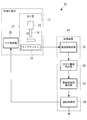
- FIG. 1 is a block diagram showing a configuration of a processing apparatus 10 according to the present embodiment.
- the processing device 10 includes an NC processing device 12 and a control device 14.
- the NC processing apparatus 12 processes the workpiece 16 by rotation of the processing tool.
- the end mill 18 is used as an example of a processing tool, and cutting is performed as an example of processing.
- the end mill 18 is rotated by being connected to the main shaft 20.
- the processing chamber 22 in which the workpiece 16 is cut by the end mill 18 is provided with a microphone 24 for detecting a sound generated by the cutting of the workpiece 16.
- the control device 14 calculates the number of rotations of the end mill 18 and outputs a control signal indicating the calculated number of rotations to the NC control board 26 provided in the NC processing device 12.
- the NC control board 26 rotates the end mill 18 based on the input control signal.
- the control device 14 includes a frequency analysis unit 28, a chatter vibration determination unit 30, an optimal rotation number calculation unit 32, and a rotation control unit 34.
- the frequency analysis unit 28 analyzes the frequency of the sound signal indicating the sound detected by the microphone 24.
- the chattering vibration determination unit 30 determines, based on the frequency output from the frequency analysis unit 28, whether chattering vibration, which is a type of self-excited vibration, occurs in the cutting of the workpiece 16. Further, the chattering vibration determination unit 30 acquires a physical quantity having a correlation with the phase difference of chatter vibration at the time of cutting, based on the detection result of the sound by the sound detection means. In the present embodiment, the chattering vibration determination unit 30 acquires chatter frequency as a physical quantity.
- the control device 14 includes an acceleration sensor for detecting the rotational acceleration of the end mill 18 on the main shaft 20 instead of the analysis of the frequency of the sound signal detected by the microphone 24, and detects the detected acceleration waveform as FFT (Fast Fourier Transform)
- FFT Fast Fourier Transform
- the optimum rotation number calculation unit 32 calculates the optimum rotation number of the end mill 18.
- the rotation control unit 34 converts the rotation number calculated by the optimum rotation number calculation unit 32 into a signal for inputting to the NC processing device 12.
- the control device 14 may be, for example, a central processing unit (CPU) or random access (RAM). Memory, and a computer readable recording medium and the like.
- CPU central processing unit
- RAM random access
- a series of processes for realizing various functions of the frequency analysis unit 28, chatter vibration determination unit 30, optimum rotation number calculation unit 32, and rotation control unit 34 are, for example, recorded in a recording medium or the like in the form of a program.
- the CPU reads this program into a RAM or the like, and executes information processing / calculation processing to realize various functions.
- chattering vibration generated in cutting of the workpiece 16 by the end mill 18 will be described.
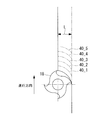
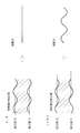
- FIG. 2 shows a state of cutting of the workpiece 16 by the end mill 18.
- the workpiece 16 is cut by the end mill 18 with the thickness L in the order of the processing surfaces 40_1, 40_2, 40_3, 40_4, and 40_5.
- the end mill 18 cuts the workpiece 16 while vibrating to receive a force. For this reason, the vibration is transferred to the workpiece 16.
- the force received by the end mill 18 is proportional to the thickness of the workpiece 16 cut.
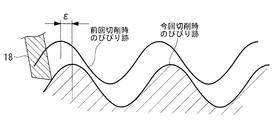
- FIG. 3 is a figure which represented the curvilinear process surface 40 in FIG. 2 in linear form.
- phase difference is calculated from the following equation (2). Further, the integer K is represented by the following equation (3). As described above, in the present embodiment, when the phase difference is represented by an integer and a small number, only the fractional part is referred to as the phase difference.
- fc is the chatter frequency [Hz]
- Z is the number of blades of the end mill 18
- n is the number of rotations.
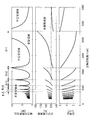
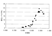
- FIG. 6 is a graph showing the number of rotations at which the end mill 18 can perform stable cutting.
- the horizontal axis represents the rotation speed of the end mill 18 (spindle rotational speed), and the vertical axis represents the axial depth (axial limit cut), chatter frequency, and phase difference of the end mill 18 capable of stable cutting. I assume.
- the graph showing the relationship between the number of revolutions of the end mill 18 and the axial limit cut in FIG. 6 is a stability limit diagram.
- the optimum number of revolutions per integer K (the broken line in FIG. 6, also referred to as a stability limit peak) at which the axial limit cutting is maximum is the apex. It is shown that stable cutting with the end mill 18 is possible on the lower side of the mountain shape (stable area).
- the optimal rotation number is a rotation number obtained by substituting the resonance frequency (natural frequency) fs of the processing apparatus 10 in place of the chatter frequency fc of the equation (1). On the other hand, cutting by the end mill 18 becomes unstable on the upper side of the mountain shape (unstable region).
- the relationship between the rotation speed of the end mill 18 and the chatter frequency indicates that the chatter frequency increases as the rotation speed increases for each range of each integer K.
- the number of rotations of the end mill 18 be close to the optimum number of rotations, which is the number of rotations corresponding to the resonance frequency of the entire processing apparatus 10.
- the microphone 24 detects a sound at the time of cutting by the end mill 18, and the frequency analysis unit 28 performs frequency analysis to obtain chatter frequency.
- the chatter frequency is determined for each different rotation speed of the end mill 18, and a graph showing the relationship between the rotation speed of the end mill 18 and the chatter frequency as shown in FIG. That is, the optimum rotational speed is determined.
- the calculated ratio (fs / fc) of the resonance frequency to the chatter frequency of the processing apparatus 10 is a correction coefficient for obtaining the resonance frequency from the phase difference.
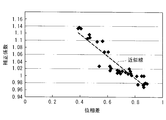
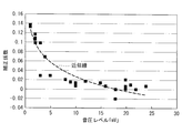
- FIG. 7 is an example of a graph showing the relationship between the phase difference and the correction coefficient, which have a correlation with chatter frequency.
- the relationship between the phase difference (chatter frequency) and the correction factor can be approximated by an approximation line. In this way, the correction factor changes according to the phase difference or chatter frequency.
- the correction coefficient is experimentally obtained in advance as described above.
- the correction coefficient is preferably determined for each different type of end mill 18, but the correction coefficient for a representative type of end mill 18 may be applied to other types of end mills 18.
- the following equation (4) calculates the resonance frequency fs of the processing apparatus 10 by multiplying the chatter frequency fc by the correction frequency R according to the chatter frequency fc, where R is the correction coefficient, and the end mill 18 based on the resonance frequency fs.
- the equation is for finding the optimum number of revolutions as the number of revolutions of
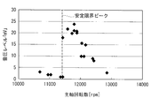
- FIG. 8 is a graph showing the relationship between the phase difference and the optimum rotation number.
- FIG. 8 corresponds to a graph obtained by superposing the relationship between the number of rotations of the end mill 18 and the axial limit cut, and the relationship between the number of rotations and the chatter frequency in FIG.
- a second phase difference threshold larger than the first phase difference threshold and the first phase difference threshold is set as a threshold for determining whether the number of rotations of the end mill 18 is close to the optimum number of rotations. Ru. If the phase difference is smaller than the first phase difference threshold, the number of rotations of the end mill 18 is increased by a first predetermined number. When the phase difference is larger than the second phase difference threshold, the number of rotations of the end mill 18 is decreased by a second predetermined number.
- the phase difference When the phase difference is smaller than the first phase difference threshold, the phase difference is close to 0, and the rotation speed of the end mill 18 is increased to be close to the optimum rotation speed.
- the phase difference when the phase difference is larger than the second phase difference threshold, the phase difference is close to 1, and the number of rotations of the end mill 18 is reduced to be close to the optimum number of rotations.
- the first predetermined number and the second predetermined number may be the same value or different values, and in the present embodiment, both are 2% of the number of rotations up to that point as an example.
- the first phase difference threshold and the second phase difference threshold are set to different values for each integral part of the phase difference.
- Table 1 below is an example of the range of the phase difference that varies depending on the integer K.
- the first phase difference threshold corresponding to each integer K is set to +0.1 of the phase difference minimum value
- the second phase difference corresponding to each integer K The threshold value is set to -0.1 of the phase difference maximum value.
- phase difference minimum value and the phase difference maximum value for each integer K by using the transfer function obtained by performing the hammering test on the end mill 18 (for example, reference “Science Eiji, generation mechanism and suppression of chatter vibration in cutting, Daido Steel Co., Ltd., Japan, Daido Steel Co., Ltd., December 27, 2011, Vol. 82, No. 2, p. 143-p. See section 155).
- the transfer function of the end of the end mill 18 is determined by a hammering test, the cutting resistance matrix is determined based on equation (14) of the above document, and the transfer function is based on equation (20) of the above document And the characteristic value of what multiplied the cutting resistance matrix is calculated
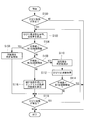
- FIG. 9 is a flow chart showing a flow of rotation speed control processing (rotation speed control program) of the end mill 18 according to the present embodiment.
- the rotation speed control process is performed by the control device 14 simultaneously with the start of cutting of the workpiece 16 by the NC processing device 12.
- the rotational speed control program may be installed in advance in a storage medium (not shown) of the control device 14, or may be provided in a state of being stored in a computer readable storage medium, through wired or wireless communication means. The form etc. which are delivered can be applied.
- the chattering vibration determination unit 30 determines whether chattering vibration occurs due to cutting. Specifically, the frequency analysis unit 28 analyzes the frequency of the sound detected by the microphone 24, and the chattering vibration determination unit 30 determines whether this frequency is within the chatter frequency range.
- step 100 the process proceeds to step 102.
- step 102 the rotation speed control process is ended. That is, in the case of a negative determination, since the rotation speed of the end mill 18 is a rotation speed that does not generate chatter vibration, the rotation speed is maintained and cutting is continued.
- the chattering vibration determination unit 30 acquires the chatter frequency and calculates the phase difference from the chatter frequency.
- the optimum rotation number calculation unit 32 determines whether the phase difference is smaller than the first phase difference threshold value. If the determination is affirmative, the process proceeds to step 106. If the determination is negative, the process proceeds to step 108. Do.
- step 106 the optimum rotation number calculation unit 32 increases the rotation number by a predetermined number, and the rotation control unit 34 outputs a control signal indicating the increased rotation number to the NC control board 26, and the process proceeds to step 118.
- the NC control board 26 rotates the end mill 18 at the rotation speed indicated by the input control signal, and continues cutting the workpiece 16.
- step 108 the optimum rotation number calculation unit 32 determines whether the phase difference is larger than the second phase difference threshold value. If the determination is affirmative, the process proceeds to step 110, and if the negative determination is made, the process proceeds to step 116.
- step 110 the optimum rotation number calculation unit 32 decreases the number of rotations by a predetermined number, and the rotation control unit 34 outputs a control signal indicating the decreased number of rotations to the NC control board 26, and proceeds to step 112.
- the NC control board 26 rotates the end mill 18 at the rotation speed indicated by the input control signal, and continues cutting the workpiece 16.
- the chattering vibration determination unit 30 acquires the chatter frequency and calculates the phase difference from the chatter frequency.
- the optimum rotation number calculation unit 32 determines whether the phase difference is smaller than the first phase difference threshold value, and in the case of a positive determination, the number of rotations of the end mill 18 is fixed and the rotation number control process is ended. If not, the process proceeds to step 118.
- step 114 the process of step 114 will be described in detail.
- the determination in step 114 is affirmative, the number of rotations of the end mill 18 is greater than the second phase difference threshold, and as a result of increasing the number of rotations of the end mill 18 by a predetermined number, the number of rotations of the end mill 18 is greater than the first phase difference threshold It is a case of becoming smaller.
- the integer part of the phase difference changes again and the phase difference becomes larger than the second phase difference threshold.
- the smaller the phase difference the smaller the sound pressure level caused by the chatter vibration, and the smaller the chatter vibration.
- the rotation speed of the end mill 18 and the sound pressure level in FIG. 11 the sound pressure level is lower as the rotation speed is lower with respect to the optimum rotation speed which is the stable limit peak. Therefore, it is understood that the smaller the phase difference, the better.
- step 114 when an affirmative determination is made in step 114, rotation is performed while being fixed without reducing the number of rotations smaller than the first phase difference threshold, and cutting of the workpiece 16 is continued.
- step 108 determines whether the phase difference is larger than the first phase difference threshold and smaller than the second phase difference threshold, that is, the number of rotations of the end mill 18 is a number of rotations away from the optimum number of rotations. Is the case.
- step 116 the optimum rotation number calculation unit 32 calculates the optimum rotation number of the end mill 18 by the equation (4) using the correction coefficient, and the rotation control unit 34 controls the NC control panel to indicate the calculated optimum rotation number. Then, the process proceeds to step 118.
- the NC control board 26 changes the speed of the end mill 18 so as to reach the rotation speed indicated by the input control signal, and continues cutting the workpiece 16. As a result, the number of rotations of the end mill 18 approaches the optimum number of rotations.
- step 118 the chattering vibration determination unit 30 determines whether chattering vibration occurs due to cutting, and in the case of a positive judgment, the process returns to step 102, the optimization of the number of rotations of the end mill 18 is repeated, and in the case of a negative judgment. Ends the rotational speed control process, and continues cutting the workpiece 16 while fixing the rotational speed of the end mill 18.
- the control device 14 of the processing apparatus 10 calculates the phase difference of chatter vibration at the time of cutting based on the detection result of the sound generated by the cutting of the workpiece 16 by the end mill 18.
- the phase difference is smaller than the first phase difference threshold, the number of rotations of the end mill 18 is increased by a predetermined number, and when the phase difference is larger than the second phase difference threshold, the number of rotations of the end mill 18 is decreased by a predetermined number.
- the control device 14 multiplies the chatter frequency by a correction coefficient that changes in accordance with the chatter frequency, whereby the processing device 10 is obtained.
- the resonance frequency is determined, and the number of rotations of the end mill 18 is calculated based on the resonance frequency.
- control device 14 when cutting the workpiece 16 by the rotation of the end mill 18, the control device 14 enables stable cutting with chatter vibration suppressed.
- FIG. 12 is a graph showing the relationship between the sound pressure level and the correction coefficient. As shown in FIG. 12, the correction coefficient can be calculated from the sound pressure level by an approximate expression.
- the first phase difference threshold and the second phase difference threshold are set as the threshold for determining whether the number of rotations of the end mill 18 is close to the optimum number of rotations. Is not limited to this, and only one threshold may be set.
- the central value of the range of the phase difference per integer K is used as a threshold, and if the phase difference is smaller than the threshold, the number of rotations of the end mill 18 is increased by a predetermined number, and if the phase difference is larger than the threshold, the end mill The number of rotations of 18 is reduced by a predetermined number. In the case of this mode, calculation of the number of revolutions of the end mill 18 and the shift using the correction coefficient as in step 116 are not performed.
- the present invention is not limited to this.
- the rotational frequency of the end mill 18 may be calculated by equation (1) using the chatter frequency fc without using it.
Landscapes
- Engineering & Computer Science (AREA)
- Mechanical Engineering (AREA)
- Human Computer Interaction (AREA)
- Manufacturing & Machinery (AREA)
- Physics & Mathematics (AREA)
- General Physics & Mathematics (AREA)
- Automation & Control Theory (AREA)
- Automatic Control Of Machine Tools (AREA)
- Numerical Control (AREA)
- Machine Tool Sensing Apparatuses (AREA)
Priority Applications (1)
| Application Number | Priority Date | Filing Date | Title |
|---|---|---|---|
| US14/650,137 US10525561B2 (en) | 2012-12-20 | 2013-12-19 | Control device for working device, working device, control program for working device, control method for working device, and working method |
Applications Claiming Priority (2)
| Application Number | Priority Date | Filing Date | Title |
|---|---|---|---|
| JP2012277911A JP6021632B2 (ja) | 2012-12-20 | 2012-12-20 | 加工装置の制御装置、加工装置、加工装置の制御プログラム、加工装置の制御方法、及び加工方法 |
| JP2012-277911 | 2012-12-20 |
Publications (1)
| Publication Number | Publication Date |
|---|---|
| WO2014098172A1 true WO2014098172A1 (ja) | 2014-06-26 |
Family
ID=50978492
Family Applications (1)
| Application Number | Title | Priority Date | Filing Date |
|---|---|---|---|
| PCT/JP2013/084027 Ceased WO2014098172A1 (ja) | 2012-12-20 | 2013-12-19 | 加工装置の制御装置、加工装置、加工装置の制御プログラム、加工装置の制御方法、及び加工方法 |
Country Status (3)
| Country | Link |
|---|---|
| US (1) | US10525561B2 (enExample) |
| JP (1) | JP6021632B2 (enExample) |
| WO (1) | WO2014098172A1 (enExample) |
Cited By (3)
| Publication number | Priority date | Publication date | Assignee | Title |
|---|---|---|---|---|
| JP2018126837A (ja) * | 2017-02-10 | 2018-08-16 | Dmg森精機株式会社 | 安定限界線図作成装置及び安定限界線図作成方法 |
| WO2018185993A1 (ja) * | 2017-04-04 | 2018-10-11 | Dmg森精機株式会社 | 主軸回転速度制御装置 |
| JP6605185B1 (ja) * | 2019-04-08 | 2019-11-13 | 三菱電機株式会社 | 数値制御装置およびびびり振動の発生判定方法 |
Families Citing this family (17)
| Publication number | Priority date | Publication date | Assignee | Title |
|---|---|---|---|---|
| JP5594685B2 (ja) * | 2010-03-30 | 2014-09-24 | 国立大学法人名古屋大学 | 工具軌跡生成装置、工具軌跡算出方法および工具軌跡生成プログラム |
| US9690282B2 (en) | 2011-02-28 | 2017-06-27 | Solidcam Ltd. | Computerized tool path generation |
| US8489224B2 (en) | 2011-02-28 | 2013-07-16 | Solidcam Ltd. | Computerized tool path generation |
| JP6625794B2 (ja) * | 2014-05-21 | 2019-12-25 | Dmg森精機株式会社 | びびり振動を抑制可能な主軸安定回転数の算出方法、その報知方法、主軸回転数制御方法及びncプログラム編集方法、並びにその装置。 |
| TWI564110B (zh) * | 2014-11-20 | 2017-01-01 | 財團法人工業技術研究院 | 回授控制數値加工機及其方法 |
| US10022832B2 (en) * | 2015-03-31 | 2018-07-17 | Dmg Mori Seiki Co., Ltd. | Fine-tuning speed application interface |
| JP6803248B2 (ja) * | 2017-01-27 | 2020-12-23 | オークマ株式会社 | 工作機械の振動抑制方法及び装置 |
| EP3602355A1 (en) * | 2017-03-20 | 2020-02-05 | Solidcam Ltd. | Computerized system and method for generating a chatter free milling cnc program for machining a workpiece |
| DE102017005488A1 (de) * | 2017-06-09 | 2018-12-13 | Blum-Novotest Gmbh | Vorrichtung und Verfahren zum Messen und Kontrollieren eines drehantreibbaren Werkzeugs in einer Werkzeugmaschine |
| JP6719678B2 (ja) * | 2017-08-28 | 2020-07-08 | 三菱電機株式会社 | 数値制御装置 |
| JP2019072806A (ja) * | 2017-10-17 | 2019-05-16 | オムロン株式会社 | 切削加工装置 |
| JP6629816B2 (ja) * | 2017-10-31 | 2020-01-15 | ファナック株式会社 | 診断装置および診断方法 |
| WO2020084772A1 (ja) * | 2018-10-26 | 2020-04-30 | 三菱電機株式会社 | 数値制御装置および数値制御方法 |
| JP7479028B2 (ja) * | 2020-03-18 | 2024-05-08 | 国立大学法人東海国立大学機構 | 工作機械の振動特性の変化を計測する方法および装置 |
| JP7721944B2 (ja) * | 2021-03-31 | 2025-08-13 | ブラザー工業株式会社 | 数値制御装置と数値制御装置の制御方法 |
| CN117120946A (zh) * | 2021-04-26 | 2023-11-24 | 三菱电机株式会社 | 数控装置、学习装置及颤振的抑制方法 |
| DE102022127965B3 (de) * | 2022-10-22 | 2024-02-01 | KAPP NILES GmbH & Co. KG | Verfahren zum Schleifen einer Verzahnung oder eines Profils eines Werkstücks |
Citations (7)
| Publication number | Priority date | Publication date | Assignee | Title |
|---|---|---|---|---|
| JP2000143022A (ja) * | 1998-11-10 | 2000-05-23 | Ricoh Co Ltd | 給紙装置 |
| JP2007044852A (ja) * | 2005-08-12 | 2007-02-22 | Univ Nagoya | 機械加工装置、機械加工装置の回転数演算装置、機械加工装置のびびり振動評価装置および機械加工装置のびびり振動評価方法 |
| JP2009291872A (ja) * | 2008-06-04 | 2009-12-17 | Univ Nagoya | 切削装置 |
| JP2010105160A (ja) * | 2010-01-15 | 2010-05-13 | Nagoya Univ | 機械加工装置、機械加工装置の回転数演算装置、機械加工装置のびびり振動評価装置および機械加工装置のびびり振動評価方法 |
| JP2012171058A (ja) * | 2011-02-22 | 2012-09-10 | Okuma Corp | 安定限界線図作成方法及び装置 |
| JP2012196741A (ja) * | 2011-03-22 | 2012-10-18 | Okuma Corp | 回転速度表示装置 |
| JP2012206230A (ja) * | 2011-03-30 | 2012-10-25 | Brother Industries Ltd | 加工びびり振動検出装置、及び工作機械 |
Family Cites Families (10)
| Publication number | Priority date | Publication date | Assignee | Title |
|---|---|---|---|---|
| JPS5153686A (en) * | 1974-11-05 | 1976-05-12 | Kogyo Gijutsuin | Kosakukikainiokeru bibirishindoyokuseihoho |
| US6507165B2 (en) * | 2000-02-10 | 2003-01-14 | Fanuc Ltd. | Controller for machine |
| JP5160980B2 (ja) | 2008-07-08 | 2013-03-13 | オークマ株式会社 | 振動抑制方法及び装置 |
| US8005574B2 (en) * | 2008-07-08 | 2011-08-23 | Okuma Corporation | Vibration suppressing method and device |
| JP5234772B2 (ja) | 2008-10-28 | 2013-07-10 | オークマ株式会社 | 工作機械の振動抑制方法及び装置 |
| JP5226484B2 (ja) | 2008-11-28 | 2013-07-03 | オークマ株式会社 | びびり振動抑制方法 |
| JP5105102B2 (ja) | 2009-04-10 | 2012-12-19 | エヌティーエンジニアリング株式会社 | 作業機械のびびり抑制方法及び装置 |
| KR101006710B1 (ko) * | 2010-08-06 | 2011-01-10 | 주식회사 창성에이스산업 | 전원 및 통신선이 포함된 누액 감시 시스템 |
| JP4942839B2 (ja) * | 2010-09-10 | 2012-05-30 | 株式会社牧野フライス製作所 | びびり振動検出方法及びびびり振動回避方法、並びに工作機械 |
| JP5525411B2 (ja) | 2010-10-25 | 2014-06-18 | オークマ株式会社 | 振動抑制方法及び振動抑制装置 |
-
2012
- 2012-12-20 JP JP2012277911A patent/JP6021632B2/ja not_active Expired - Fee Related
-
2013
- 2013-12-19 US US14/650,137 patent/US10525561B2/en not_active Expired - Fee Related
- 2013-12-19 WO PCT/JP2013/084027 patent/WO2014098172A1/ja not_active Ceased
Patent Citations (7)
| Publication number | Priority date | Publication date | Assignee | Title |
|---|---|---|---|---|
| JP2000143022A (ja) * | 1998-11-10 | 2000-05-23 | Ricoh Co Ltd | 給紙装置 |
| JP2007044852A (ja) * | 2005-08-12 | 2007-02-22 | Univ Nagoya | 機械加工装置、機械加工装置の回転数演算装置、機械加工装置のびびり振動評価装置および機械加工装置のびびり振動評価方法 |
| JP2009291872A (ja) * | 2008-06-04 | 2009-12-17 | Univ Nagoya | 切削装置 |
| JP2010105160A (ja) * | 2010-01-15 | 2010-05-13 | Nagoya Univ | 機械加工装置、機械加工装置の回転数演算装置、機械加工装置のびびり振動評価装置および機械加工装置のびびり振動評価方法 |
| JP2012171058A (ja) * | 2011-02-22 | 2012-09-10 | Okuma Corp | 安定限界線図作成方法及び装置 |
| JP2012196741A (ja) * | 2011-03-22 | 2012-10-18 | Okuma Corp | 回転速度表示装置 |
| JP2012206230A (ja) * | 2011-03-30 | 2012-10-25 | Brother Industries Ltd | 加工びびり振動検出装置、及び工作機械 |
Cited By (6)
| Publication number | Priority date | Publication date | Assignee | Title |
|---|---|---|---|---|
| JP2018126837A (ja) * | 2017-02-10 | 2018-08-16 | Dmg森精機株式会社 | 安定限界線図作成装置及び安定限界線図作成方法 |
| WO2018146913A1 (ja) * | 2017-02-10 | 2018-08-16 | Dmg森精機株式会社 | 安定限界線図作成装置及び安定限界線図作成方法 |
| WO2018185993A1 (ja) * | 2017-04-04 | 2018-10-11 | Dmg森精機株式会社 | 主軸回転速度制御装置 |
| JP2018176296A (ja) * | 2017-04-04 | 2018-11-15 | Dmg森精機株式会社 | 主軸回転速度制御装置 |
| JP6605185B1 (ja) * | 2019-04-08 | 2019-11-13 | 三菱電機株式会社 | 数値制御装置およびびびり振動の発生判定方法 |
| WO2020208685A1 (ja) * | 2019-04-08 | 2020-10-15 | 三菱電機株式会社 | 数値制御装置およびびびり振動の発生判定方法 |
Also Published As
| Publication number | Publication date |
|---|---|
| US10525561B2 (en) | 2020-01-07 |
| JP2014121741A (ja) | 2014-07-03 |
| US20150306720A1 (en) | 2015-10-29 |
| JP6021632B2 (ja) | 2016-11-09 |
Similar Documents
| Publication | Publication Date | Title |
|---|---|---|
| JP6021632B2 (ja) | 加工装置の制御装置、加工装置、加工装置の制御プログラム、加工装置の制御方法、及び加工方法 | |
| JP5525411B2 (ja) | 振動抑制方法及び振動抑制装置 | |
| CN101722438B (zh) | 机床的振动抑制方法和装置 | |
| CN101310921B (zh) | 机床的振动抑制装置和振动抑制方法 | |
| JP4743646B2 (ja) | 工作機械の振動抑制装置 | |
| TWI289092B (en) | Detecting and suppressing methods for milling tool chatter | |
| CN101417398B (zh) | 振动抑制方法及装置 | |
| JP4177028B2 (ja) | 小径エンドミルによる加工方法及び加工条件決定方法 | |
| JP4433422B2 (ja) | 振動抑制装置 | |
| JP5802062B2 (ja) | 工作機械の制御装置及び制御方法 | |
| US20090110499A1 (en) | Method for suppressing vibration and device therefor | |
| JP5622626B2 (ja) | 回転速度表示装置 | |
| WO2012133222A1 (ja) | 工作機械及びその加工制御装置 | |
| CN101623835A (zh) | 振动抑制方法及装置 | |
| JP2014140918A (ja) | 切削振動抑止方法、演算制御装置、および工作機械 | |
| JP5631779B2 (ja) | 工作機械の振動抑制方法及び装置 | |
| CN110102787B (zh) | 一种基于幅值调制的变主轴转速车削颤振抑制方法 | |
| JP5155090B2 (ja) | 工作機械の振動判定方法及び振動抑制装置 | |
| JP2013220479A (ja) | びびり振動の抑制システム及び抑制方法 | |
| JP5226484B2 (ja) | びびり振動抑制方法 | |
| JP5587707B2 (ja) | 振動抑制装置 | |
| JP5767931B2 (ja) | 工作機械の振動抑制方法および振動抑制装置 | |
| JP2021020260A (ja) | 工作機械の主軸回転数制御装置および制御方法 | |
| JP4995115B2 (ja) | 振動抑制方法及び装置 | |
| KR20190133888A (ko) | 가속도 센서를 이용한 채터 감지 방법 및 시스템 |
Legal Events
| Date | Code | Title | Description |
|---|---|---|---|
| 121 | Ep: the epo has been informed by wipo that ep was designated in this application |
Ref document number: 13864600 Country of ref document: EP Kind code of ref document: A1 |
|
| WWE | Wipo information: entry into national phase |
Ref document number: 14650137 Country of ref document: US |
|
| NENP | Non-entry into the national phase |
Ref country code: DE |
|
| 122 | Ep: pct application non-entry in european phase |
Ref document number: 13864600 Country of ref document: EP Kind code of ref document: A1 |