WO2014097839A1 - 不織布及びその製造方法 - Google Patents
不織布及びその製造方法 Download PDFInfo
- Publication number
- WO2014097839A1 WO2014097839A1 PCT/JP2013/081995 JP2013081995W WO2014097839A1 WO 2014097839 A1 WO2014097839 A1 WO 2014097839A1 JP 2013081995 W JP2013081995 W JP 2013081995W WO 2014097839 A1 WO2014097839 A1 WO 2014097839A1
- Authority
- WO
- WIPO (PCT)
- Prior art keywords
- nonwoven fabric
- convex
- less
- roller
- concave
- Prior art date
- Legal status (The legal status is an assumption and is not a legal conclusion. Google has not performed a legal analysis and makes no representation as to the accuracy of the status listed.)
- Ceased
Links
Images




Classifications
-
- D—TEXTILES; PAPER
- D04—BRAIDING; LACE-MAKING; KNITTING; TRIMMINGS; NON-WOVEN FABRICS
- D04H—MAKING TEXTILE FABRICS, e.g. FROM FIBRES OR FILAMENTARY MATERIAL; FABRICS MADE BY SUCH PROCESSES OR APPARATUS, e.g. FELTS, NON-WOVEN FABRICS; COTTON-WOOL; WADDING ; NON-WOVEN FABRICS FROM STAPLE FIBRES, FILAMENTS OR YARNS, BONDED WITH AT LEAST ONE WEB-LIKE MATERIAL DURING THEIR CONSOLIDATION
- D04H3/00—Non-woven fabrics formed wholly or mainly of yarns or like filamentary material of substantial length
- D04H3/08—Non-woven fabrics formed wholly or mainly of yarns or like filamentary material of substantial length characterised by the method of strengthening or consolidating
- D04H3/14—Non-woven fabrics formed wholly or mainly of yarns or like filamentary material of substantial length characterised by the method of strengthening or consolidating with bonds between thermoplastic yarns or filaments produced by welding
-
- A—HUMAN NECESSITIES
- A61—MEDICAL OR VETERINARY SCIENCE; HYGIENE
- A61F—FILTERS IMPLANTABLE INTO BLOOD VESSELS; PROSTHESES; DEVICES PROVIDING PATENCY TO, OR PREVENTING COLLAPSING OF, TUBULAR STRUCTURES OF THE BODY, e.g. STENTS; ORTHOPAEDIC, NURSING OR CONTRACEPTIVE DEVICES; FOMENTATION; TREATMENT OR PROTECTION OF EYES OR EARS; BANDAGES, DRESSINGS OR ABSORBENT PADS; FIRST-AID KITS
- A61F13/00—Bandages or dressings; Absorbent pads
- A61F13/15—Absorbent pads, e.g. sanitary towels, swabs or tampons for external or internal application to the body; Supporting or fastening means therefor; Tampon applicators
- A61F13/51—Absorbent pads, e.g. sanitary towels, swabs or tampons for external or internal application to the body; Supporting or fastening means therefor; Tampon applicators characterised by the outer layers of the pads
-
- D—TEXTILES; PAPER
- D04—BRAIDING; LACE-MAKING; KNITTING; TRIMMINGS; NON-WOVEN FABRICS
- D04H—MAKING TEXTILE FABRICS, e.g. FROM FIBRES OR FILAMENTARY MATERIAL; FABRICS MADE BY SUCH PROCESSES OR APPARATUS, e.g. FELTS, NON-WOVEN FABRICS; COTTON-WOOL; WADDING ; NON-WOVEN FABRICS FROM STAPLE FIBRES, FILAMENTS OR YARNS, BONDED WITH AT LEAST ONE WEB-LIKE MATERIAL DURING THEIR CONSOLIDATION
- D04H11/00—Non-woven pile fabrics
- D04H11/08—Non-woven pile fabrics formed by creation of a pile on at least one surface of a non-woven fabric without addition of pile-forming material, e.g. by needling, by differential shrinking
-
- D—TEXTILES; PAPER
- D04—BRAIDING; LACE-MAKING; KNITTING; TRIMMINGS; NON-WOVEN FABRICS
- D04H—MAKING TEXTILE FABRICS, e.g. FROM FIBRES OR FILAMENTARY MATERIAL; FABRICS MADE BY SUCH PROCESSES OR APPARATUS, e.g. FELTS, NON-WOVEN FABRICS; COTTON-WOOL; WADDING ; NON-WOVEN FABRICS FROM STAPLE FIBRES, FILAMENTS OR YARNS, BONDED WITH AT LEAST ONE WEB-LIKE MATERIAL DURING THEIR CONSOLIDATION
- D04H3/00—Non-woven fabrics formed wholly or mainly of yarns or like filamentary material of substantial length
- D04H3/018—Non-woven fabrics formed wholly or mainly of yarns or like filamentary material of substantial length characterised by the shape
-
- D—TEXTILES; PAPER
- D04—BRAIDING; LACE-MAKING; KNITTING; TRIMMINGS; NON-WOVEN FABRICS
- D04H—MAKING TEXTILE FABRICS, e.g. FROM FIBRES OR FILAMENTARY MATERIAL; FABRICS MADE BY SUCH PROCESSES OR APPARATUS, e.g. FELTS, NON-WOVEN FABRICS; COTTON-WOOL; WADDING ; NON-WOVEN FABRICS FROM STAPLE FIBRES, FILAMENTS OR YARNS, BONDED WITH AT LEAST ONE WEB-LIKE MATERIAL DURING THEIR CONSOLIDATION
- D04H3/00—Non-woven fabrics formed wholly or mainly of yarns or like filamentary material of substantial length
- D04H3/08—Non-woven fabrics formed wholly or mainly of yarns or like filamentary material of substantial length characterised by the method of strengthening or consolidating
- D04H3/16—Non-woven fabrics formed wholly or mainly of yarns or like filamentary material of substantial length characterised by the method of strengthening or consolidating with bonds between thermoplastic filaments produced in association with filament formation, e.g. immediately following extrusion
-
- D—TEXTILES; PAPER
- D06—TREATMENT OF TEXTILES OR THE LIKE; LAUNDERING; FLEXIBLE MATERIALS NOT OTHERWISE PROVIDED FOR
- D06C—FINISHING, DRESSING, TENTERING OR STRETCHING TEXTILE FABRICS
- D06C11/00—Teasing, napping or otherwise roughening or raising pile of textile fabrics
-
- D—TEXTILES; PAPER
- D06—TREATMENT OF TEXTILES OR THE LIKE; LAUNDERING; FLEXIBLE MATERIALS NOT OTHERWISE PROVIDED FOR
- D06C—FINISHING, DRESSING, TENTERING OR STRETCHING TEXTILE FABRICS
- D06C3/00—Stretching, tentering or spreading textile fabrics; Producing elasticity in textile fabrics
- D06C3/06—Stretching, tentering or spreading textile fabrics; Producing elasticity in textile fabrics by rotary disc, roller, or like apparatus
Definitions
- the present invention relates to a nonwoven fabric containing long fibers and a method for producing the same.
- spunbonded nonwoven fabrics are frequently used because they are high in breaking strength, excellent in processing suitability, and economical.
- the spunbonded nonwoven fabric has a lack of plumpness due to its manufacturing method, and it has been difficult to improve the touch feeling at the moment of touch.
- the present applicant has previously proposed a non-woven fabric comprising fibers in which a part of a long fiber is broken, only one end is fixed by a heat-sealed portion, and the free end on the other end is thickened. (See Patent Document 1).
- This invention relates to the nonwoven fabric which fixed the web containing a long fiber by the heat-fusion part.
- the non-woven fabric includes a fiber in which a part of the long fiber is broken and only one end is fixed by the heat-sealing part.
- the portion located between the heat fusion portions adjacent to each other in the orientation direction of the long fibers has an elongation of 35% or more with respect to a tensile load of 1 cN / 1 mm.
- the present invention provides a method for producing a nonwoven fabric in which a plurality of portions of the nonwoven fabric are partially stretched at a temperature of 50 ° C. or less, and the nonwoven fabric subjected to the partial stretching processing is subjected to raising processing for raising constituent fibers of the nonwoven fabric.
- the raising process is performed using a convex roller having a plurality of convex portions on the peripheral surface.
- the convex portions are arranged in a random pattern in at least one of the rotation axis direction and the circumferential direction.
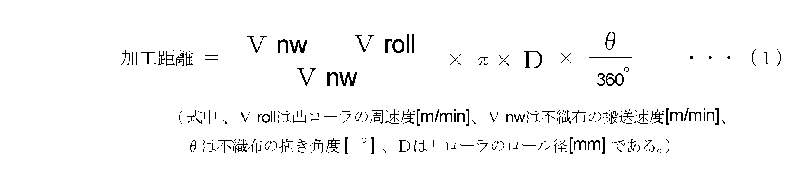
- the convex roller has a processing distance of 350 mm or more obtained by the following formula (1).
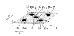
- FIG. 1 is a perspective view showing an embodiment of the nonwoven fabric of the present invention.
- 2 is a cross-sectional view taken along the line II shown in FIG.
- FIG. 3 is an explanatory diagram for explaining a method of measuring the elongation of a portion located between adjacent heat-sealed portions.
- FIG. 4 is a schematic view showing a method for measuring the amount of raised fibers of the nonwoven fabric of the present invention.
- FIG. 5 is a schematic view showing a preferred production apparatus used in the method for producing a nonwoven fabric of the present invention.
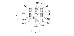
- FIG. 6 is a schematic diagram showing a partially stretched portion provided in the manufacturing apparatus shown in FIG.
- FIG. 7 is an enlarged cross-sectional view of a main part of the partially stretched portion shown in FIG. FIG.
- FIG. 8 is an enlarged cross-sectional view of a main part when the first uneven roller and the second uneven roller of the partially extending portion shown in FIG.
- FIG. 9 shows a position d 1/2 that bisects the engagement depth d 0 when the first uneven roller and the second uneven roller of the partially stretched portion shown in FIG. It is the plane sectional view which looked at the plane section.
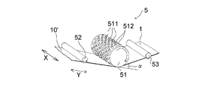
- FIG. 10 is a schematic diagram showing a raised processing portion provided in the manufacturing apparatus shown in FIG.
- FIG. 11 is a diagram showing a random pattern of convex portions of the raised portion shown in FIG.
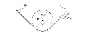
- FIG. 12 is an explanatory diagram for explaining a processing distance by the convex roller provided in the raised processing unit.
- FIG. 10 is a schematic diagram showing a raised processing portion provided in the manufacturing apparatus shown in FIG.
- FIG. 11 is a diagram showing a random pattern of convex portions of the raised portion shown in FIG.
- FIG. 12 is an explanatory diagram for explaining a processing distance by the convex roller provided in
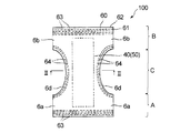
- FIG. 13 is a diagram for explaining an example of the usage pattern of the nonwoven fabric of the present invention, and is a developed plan view showing a state in which a pants-type disposable diaper is developed and extended.
- 14 is a sectional view taken along line II-II in FIG.
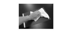
- FIG. 15 is a diagram illustrating a situation in which sensory evaluation of touch is performed.
- FIG. 16 is a diagram illustrating a situation in which sensory evaluation of a touch feeling is performed.
- the nonwoven fabric 1 of the present embodiment is a nonwoven fabric in which a web including long fibers 2 is fixed by a heat fusion part 3, and a part of the long fibers 2 is broken, and only one end 20 a. Is provided with a fiber 20 fixed by the heat-sealing part 3.
- the nonwoven fabric 1 will be described below with the longitudinal direction of the nonwoven fabric 1 as the Y direction and the width direction of the nonwoven fabric 1 as the X direction, as shown in FIG.
- the MD direction along the fiber orientation direction is determined as the longitudinal direction (Y direction) and the CD direction perpendicular to the MD direction along the fiber orientation direction is determined as the width direction (X direction). Therefore, in the following description, the Y direction and the MD direction mean the same direction, and the X direction and the CD direction mean the same direction.
- the non-woven fabric 1 of this embodiment will be described in detail.
- the non-woven fabric 1 is a spunbonded non-woven fabric 10 in which a web containing long fibers 2 is intermittently crimped or fused with each other by a heat-sealing portion 3 and fixed. It is formed based on.
- this will be described as the original spunbond nonwoven fabric (raw material nonwoven fabric) 10.
- the raw material nonwoven fabric 10 is a nonwoven fabric before breaking a part of the long fibers 2.
- the “long fiber” has a fiber length of 30 mm or more, and the raw nonwoven fabric 10 is preferably a so-called continuous long fiber having a fiber length of 150 mm or more because a nonwoven fabric 1 having high breaking strength can be obtained. .
- the nonwoven fabric 1 is inexpensive and can provide a good touch feeling, and the basis weight is preferably 5 g / m 2 or more, and preferably 100 g / m 2 or less from the viewpoint of processing suitability. 25 g / m 2 or less, more preferably 5 g / m 2 or more and 100 g / m 2 or less, more preferably 5 g / m 2 or more and 25 g / m 2 or less.
- the non-woven fabric 1 has a 1 cN / 1 mm tensile portion located between the heat fusion portions 3 and 3 adjacent to each other in the orientation direction (Y direction) of the long fibers 2.
- the elongation is 35% or more with respect to the load, preferably 40% or more, more preferably 50% or more, and particularly preferably 60% or more.
- the elongation is preferably 200% or less, more preferably 150% or less, and particularly preferably 120% or less.
- the elongation is 1 cN / 1 mm.
- the elongation is preferably 40% or more and 200% or less with respect to the tensile load, more preferably 50% or more and 150% or less, particularly 60% or more and 120% or less. Is preferred.
- the measuring method of elongation is shown below, it is an elongation between the heat fusion parts 3 of the nonwoven fabric 1 or the raw material nonwoven fabric 10.
- a plurality of fibers between the embosses fixed by embossing are usually intertwined with each other and are difficult to move when an external force is applied, but the nonwoven fabric 1 having an elongation of 35% or more is fixed by embossing.
- the elongation is measured by the following method.
- the Y-direction of the region T extends from both side edges along the Y-direction of the rectangular measurement piece at an intermediate position in the Y-direction of the two heat-sealing portions 3 and 3.
- a measurement sample is prepared by making cuts extending in the X direction to the positions of both side edges.
- the measurement sample is attached to a chuck of a tensile tester (for example, Tensilon tensile tester “RTA-100” manufactured by Orientec Co., Ltd.) so that the Y direction is the tensile direction.
- the distance between chucks is 25 mm.
- the measurement sample is pulled at 50 mm / min, and the elongation (%) is measured when a tensile load of 1 cN / 1 mm is applied to a width of 1 mm.
- the nonwoven fabric 1 has a breaking strength value of preferably 5.00 N / 50 mm or more, more preferably 8 N / 50 mm or more and 30 N / 50 mm or less, from the viewpoint of prevention of breakage during use and processing suitability. preferable.
- the value of the breaking strength of the raw nonwoven fabric 10 is preferably 7 N / 50 mm or more, and more preferably 10 N / 50 mm or more and 50 N / 50 mm or less, from the viewpoint of achieving the breaking strength of the nonwoven fabric 1.
- the manufacturing method of the nonwoven fabric 1 mentioned later is a method with little fall from the value of the breaking strength of the raw material nonwoven fabric 10 compared with the other conventional raising method.
- the breaking strength of the nonwoven fabric 1 and the raw material nonwoven fabric 10 satisfies the above range in the X direction (CD direction).
- the ratio of the breaking strength between the nonwoven fabric 1 and the raw material nonwoven fabric 10 is 0.5 or more, preferably 0.7 or more and 1.0 or less, more specifically. Is preferably 0.5 or more and 1.0 or less, and more preferably 0.7 or more and 1.0 or less.
- the breaking strength is measured by the following method.
- a rectangular measuring piece having a size of 200 mm in the X direction (width direction) and 50 mm in the Y direction (longitudinal direction) is cut out from the nonwoven fabric 1 or the raw material nonwoven fabric 10.
- the cut out rectangular measurement piece is used as a measurement sample.
- the measurement sample is attached to a chuck of a tensile tester (for example, Tensilon tensile tester “RTA-100” manufactured by Orientec Co., Ltd.) so that the X direction is the tensile direction.
- the distance between chucks is 150 mm.
- the measurement sample is pulled at 300 mm / min, and the maximum load point until the sample breaks is defined as the breaking strength in the X direction. Further, a rectangular measurement piece having a size of 200 mm in the Y direction and 50 mm in the X direction is cut out and used as a measurement sample. This measurement sample is attached to the chuck of a tensile tester so that the Y direction is the tensile direction. The breaking strength in the Y direction is obtained by the same procedure as the method for measuring the breaking strength in the X direction described above.
- the nonwoven fabric 1 has a bulk softness of preferably 4.5 cN or less, more preferably 3 cN or less, still more preferably 2.5 cN or less, and more preferably 0.1 cN or more from the viewpoint of excellent bulk softness. It is preferable that it is 0.5 cN or more. Specifically, it is preferably 0.1 cN or more and 4.5 cN or less, more preferably 0.1 cN or more and 3 cN or less, in terms of becoming supple, such as a baby or infant. More preferably, it is 5 cN or more and 2.5 cN or less.
- the raw nonwoven fabric 10 has a bulk softness of preferably 10 cN or less, more preferably 6 cN or less, and more preferably 1 cN or more from the viewpoint of obtaining a soft and soft feel. Specifically, it is preferably 0.5 cN or more and 10 cN or less, and more preferably 1 cN or more and 8 cN or less. Bulk softness is measured by the following measurement method.
- the bulk softness of the nonwoven fabric 1 is obtained by cutting the nonwoven fabric 1 in the Y direction (longitudinal direction) 150 mm and the X direction (width direction) 30 mm in a 22 ° C. and 65% RH environment, and using a stapler in a ring shape with a diameter of 45 mm. Stop the edges at the top and bottom. At this time, the stapler core is elongated in the Y direction (longitudinal direction).
- the ring is placed in a cylindrical shape on the sample stage, and the compression speed is 10 mm on a flat plate substantially parallel to the stage from above. Measure the maximum load when compressing at a rate of / min and make it bulk bulkiness.
- a tensile tester for example, Tensilon tensile tester “RTA-100” manufactured by Orientec Co., Ltd.
- the nonwoven fabric 1 has a compression characteristic value at the time of a minute load of 14.7 (cN / cm 2 ) / mm (15 (gf / cm 2 ) / mm) or less from the viewpoint of providing a soft feeling. Is preferably 11.8 (cN / cm 2 ) / mm (12 (gf / cm 2 ) / mm) or less, more preferably 10.8 (cN / cm 2 ) / mm (11 (gf / cm 2 ) / mm) or less is more preferable.
- the lower limit of the compression characteristic value of the nonwoven fabric 1 is not particularly limited, but is about 1.0 (cN / cm 2 ) / mm (1.0 (gf / cm 2 ) / mm) from the viewpoint of production.
- the compression characteristic value of the raw material nonwoven fabric 10 having a basis weight of about 5 to 25 g / m 2 that has not been processed is 19.6 (cN / cm 2 ) / mm (20.0 (gf / cm 2 ) / Mm) to 29.4 (cN / cm 2 ) / mm (30.0 (gf / cm 2 ) / mm).
- the compression characteristic value at a minute load is measured by the method described in Japanese Patent Application Laid-Open No. 2012-92475. This will be specifically described below.
- Measurement of the data that is the basis for calculating the compression characteristic value at the time of a minute load is performed using KES FB3-AUTO-A (trade name) manufactured by Kato Tech Co., Ltd. in an environment of 22 ° C. and 65% RH. Specifically, three nonwoven fabrics 1 are cut into 20 cm ⁇ 20 cm to prepare measurement samples. Next, one of the measurement samples is placed on the test stand with the raised surface facing upward (if not raised, or if both surfaces are raised, measure both and adopt the smaller one). Next, it compresses between the steel plates of the circular plane of area 2cm ⁇ 2 >.
- the compression rate is 20 ⁇ m / sec
- the maximum compression load is 9.80 cN / cm 2 (10.0 gf / cm 2 )
- the recovery process is also measured at the same rate.
- the amount of displacement between the steel plates is x (mm)
- the load is y (cN / cm 2 )
- the value of x increases as it is compressed.
- the compression characteristic value at the minute load is calculated by extracting the deformation amount of the thickness at the minute load from the measured data (x, y).
- the first load that is not a recovery process is a load between 0.29 cN / cm 2 (0.30 gf / cm 2 ) and 0.98 cN / cm 2 (1.00 gf / cm 2 ), and at that time
- the amount of deformation data is extracted, an approximate straight line is obtained for the relationship between x and y by the least square method, and the slope at that time is defined as the characteristic value (unit (cN / cm 2 ) / mm). Three points are measured with one measurement sample. A total of 9 points of 3 samples are measured.
- the characteristic values at each of the nine locations are calculated, and the average value is set as the compression characteristic value when the nonwoven fabric is subjected to a minute load.
- the compression characteristic value at the time of a minute load indicates that the lower the numerical value, the easier it is to be crushed with a smaller load, and it is possible to express the good feeling (particularly plump feeling) when the nonwoven fabric is rubbed.
- the raised fiber including the fiber 20 in which only one end 20a is fixed by the heat-sealing part 3 is 10 / cm or more from the viewpoint of improving the touch.
- the number is 15 / cm or more.
- the upper limit is preferably 50 pieces / cm or less.
- the “raised fiber” means a loop between the fiber 20 in which only one end portion 20 a is fixed by the heat fusion part 3 and the heat fusion parts 3, 3 in the nonwoven fabric 1.
- the fiber which consists of the loop-shaped fiber 21 standing up in the shape is meant.
- the amount of the raised fiber is measured by the following measuring method. As shown in FIG. 2, the loop-shaped fiber 21 means a fiber that does not have a free end portion and is fixed at both ends by the heat-sealing portion 3.
- FIG. 4 is a schematic view showing a method for measuring the amount of fibers raised in the fibers constituting the nonwoven fabric 1 in an environment of 22 ° C. and 65% RH.
- a 20 cm ⁇ 20 cm measuring piece is cut out with a sharp razor, and as shown in FIG. 4A, X passes through a plurality of heat-sealed portions 3 on the raised surface of the measuring piece.
- a measurement sample 104 is formed by folding in a fold line Z extending in the direction.
- this measurement sample 104 is placed on an A4 size black mount, and as shown in FIG.
- an A4 size black mount in which holes 107 of 1 cm in length and 1 cm in width are further formed. Put on. At this time, as shown in FIG. 4B, the fold 105 of the measurement sample 104 is arranged so that it can be seen from the hole 107 of the upper black mount.
- “Kenran (black) continuous weight 265 g” of Fuji Kyowa Paper Co., Ltd. was used. Thereafter, a weight of 50 g is placed on each side of the upper mount hole 107 at a position 5 cm outward along the fold line 105 to create a state in which the measurement sample 104 is completely folded.
- FIG. 4B an A4 size black mount in which holes 107 of 1 cm in length and 1 cm in width are further formed.
- the inside of the mount hole 107 is observed at a magnification of 30 times using a microscope (VHX-900 manufactured by KEYENCE), and the measurement sample 104 has a fold 105 to 0.
- the fiber when counting the number of raised fibers, for example, there is a fiber that crosses the virtual line 108 that is 0.2 mm above the fold 105 twice, such as a fiber 106a shown in FIG.
- the fiber counts as two. Specifically, in the example shown in FIG. 4C, there are four fibers crossing the virtual line 108 once and one fiber 106a crossing the virtual line 108 twice, but two fibers 106a crossing the virtual line 108 twice. Counted as a book, the amount of raised fibers is 6 / cm.
- the raised fibers preferably have a height of 0.7 mm or more, and more preferably 2.0 mm or more, from the viewpoint of enhancing the feeling of plumpness and enhancing the touch feeling.
- the height of the raised fiber exceeds 5 mm, the appearance becomes fluffy, and when it is rubbed during use, it becomes fluffy or fluffy.
- the height of the raised fiber is preferably 5 mm or less, and more preferably 3 mm or less.
- the height of the raised fiber means the fiber height in a natural state without pulling the fiber during measurement, unlike the length of the fiber. When the value of the length of the raised fiber is large or the rigidity of the fiber is high, the height of the raised fiber tends to increase.
- the height of the raised fiber is measured by the following measurement method.
- the height of the raised fiber is measured at the same time as measuring the amount of the raised fiber. Specifically, as shown in FIG. 4C, the inside of the hole 107 of the mount is observed, and a line is drawn in parallel from the crease 105 to a point where fibers that are raised every 0.05 mm do not intersect. Next, compared to the amount of raised fibers measured as described above (determined from the imaginary line 108 above 0.2 mm), a parallel line that halves the fibers that intersect the parallel line is selected, and from there Measure the distance to the crease. Three sheets are measured for the nonwoven fabric for measuring the above operation, and an average of nine places in three places and three pieces per piece is taken as the height of the raised fiber.
- the heat-sealed portion 3 by embossing shown in FIGS. 1 and 2 preferably has an area of each heat-fused portion 3 of 0.05 mm 2 or more and 10 mm 2 or less from the viewpoint of touch and suitability for processing. and more preferably 1 mm 2 or more 1 mm 2 or less.
- the number of heat-sealing portions 3 is preferably 10 / cm 2 or more and 250 / cm 2 or less, and more preferably 35 / cm 2 or more and 65 / cm 2 or less.
- the distance between the centers of the heat fusion parts 3 adjacent in the X direction is preferably 0.5 mm or more and 10 mm or less, more preferably 1 mm or more and 3 mm or less, and the heat fusion part adjacent in the Y direction.
- the distance between the centers of the three is preferably 0.5 mm or more and 10 mm or less, and more preferably 1 mm or more and 3 mm or less.
- the heat fusion part 3 was intermittently formed by thermocompression bonding by embossing (by using an embossed convex roller and a flat roller), by ultrasonic welding, or intermittently heated and partially fused. Things. Among these, the thermocompression bonding is preferable in that the fiber is easily broken.
- the shape of the heat fusion part 3 is not particularly limited, and may be any shape such as a circle, a rhombus, and a triangle in addition to the ellipse shown in FIG.
- the ratio of the total area of the heat fusion part 3 to the surface area of one surface of the nonwoven fabric 1 is preferably 5% or more and 30% or less, and it is 10% or more and 20% or less because it is difficult to produce pills. Further preferred.
- the manufacturing apparatus 200 that is preferably used in the method for manufacturing the nonwoven fabric 1 is roughly divided into a partially stretched portion 4 and a raised portion 5 disposed on the downstream side of the partially stretched portion 4.
- the partially stretched portion 4 is a portion that performs a partially stretched process on each of a plurality of portions of the nonwoven fabric 10.
- the first uneven roller (first type) 41 and the second uneven roller (second type) 42 are provided.
- the “partial stretching” process referred to here is a method of processing so as to have an unstretched part and a stretched part instead of subjecting the entire nonwoven fabric to a stretching process due to a difference in speed between rollers. .
- the unstretched portion is a portion of the nonwoven fabric that has not been stretched, and “do not stretch” means that the stretch treatment is not actively applied.
- the first uneven roller 41 is adjacent to a plurality of convex portions 411 regularly arranged in the transport direction (Y direction) and the width direction (X direction) in the transport direction (Y direction). It has the some convex part 411 and the some recessed part 412 distribute
- the second concavo-convex roller 42 also has a plurality of convex portions 421 regularly arranged in the transport direction (Y direction) and the width direction (X direction), and the transport direction (Y direction). And the plurality of concave portions 422 arranged between the convex portions 421 adjacent to each other in the width direction (X direction).
- the concave and convex rollers 41 and 42 are rotated in the circumferential direction.
- the convex portions 411 and the plurality of convex portions 421 of the second concave-convex roller 42 are respectively disposed on the peripheral surfaces of the concave-convex rollers 41, 42, and are uniform in the circumferential direction and the rotation axis direction (X direction). Arranged regularly.
- the convex portion 411 of the first concave / convex roller 41 is disposed at a position corresponding to the concave portion 422 of the second concave / convex roller 42, and the convex portion 421 of the second concave / convex roller 42 corresponds to the concave portion 412 of the first concave / convex roller 41. It is arranged in.
- first concavo-convex rollers 41 and second concavo-convex rollers 42 are so-called steel matching emboss rollers.
- the top shapes of the convex portions 411 of the first concave / convex roller 41 and the convex portions 421 of the second concave / convex roller 22 are circular, quadrangular (diamond, rectangular, etc.), elliptical, polygonal (hexagon, eight (Square, dodecagon, dodecagon, etc.).
- the area of the top surface of the convex portions 411 and 421 is preferably 1 mm 2 or more and 100 mm 2 or less from the viewpoint of improving the softness of the nonwoven fabric 4 after processing while preventing penetration during processing of the nonwoven fabric 4. and more preferably 2 or more 25 mm 2 or less.
- It edge portion of the top of the convex portions 411 and 421 is R-shaped, preferably from the viewpoint of nonwoven fabric pores is less likely to open at the time of processing, 0.2 mm or more 0.5mm or less ⁇ dots long as R value A 1 (Distance in the circumferential direction of the top of the convex portions 411, 421) or 0.2 mm to 0.5 mm ⁇ dot length A 2 (distance in the X direction of the top of the convex portions 411, 421) 7).
- the area of the top surface of the convex portions 411 and 421 is an R intermediate point (projecting the convex portion from the upper surface). The partial mechanical stretch ratio described later is similarly determined from the midpoint.
- the shape of the convex portions 411 and 421 viewed from the side includes a trapezoidal shape, a quadrangular shape, a curved shape or the like as shown in FIG.
- a trapezoid or a rectangle is preferable, and an average elevation angle (base angle) ⁇ (see FIG. 8) of the trapezoid is preferably 77 ° or more.
- base angle base angle
- the gap it is more preferably 85 ° or more and 150 ° or less.
- the convex portions 411 of the first uneven roller 41 are uniform, and the height h 1 (see FIG. 8) from the peripheral surface of the roller 41 to the apex of the convex portion 411 is preferably 1 to 10 mm. More preferably, it is ⁇ 7 mm.
- the distance (pitch) between the convex portions 411 adjacent to each other in the rotation axis direction (X direction) is preferably 0.01 mm or more and 20 mm or less, more preferably 1 mm or more and 10 mm or less, and projections adjacent in the circumferential direction.
- the distance between the portions 411 (pitch P 1 see FIG.
- the height h 1 of the convex portion 411 of the first concave / convex roller 41 and the height h 2 of the convex portion 421 of the second concave / convex roller 42 are different from each other.
- the convex portion 421 of the concave / convex roller 42 is formed higher than the convex portion 411 of the first concave / convex roller 41.
- the top shapes of the convex portions 411 of the first concave / convex roller 41 and the convex portions 421 of the second concave / convex roller 42, and the bottom shapes of the concave portions 412 of the first concave / convex roller 41 and the concave portions 422 of the second concave / convex roller 42, respectively. May be the same or different, but from the viewpoint of forming a gap (gap between the convex portion 411 of the first concave-convex roller 41 and the convex portion 421 of the second concave-convex roller 42) during roller rotation , May be different.
- the area of the bottom surface of the concave portions 412 and 422 is larger than the area of the top surface of the convex portions 411 and 421, and the area of the bottom surface of the concave portions 412 and 422 is 4 mm 2 or more and 225 mm 2 or less. Preferably, it is 4 mm 2 or more and 36 mm 2 or less.
- the area ratio of the area of the top of the concavo-convex roller (ratio of the area of the top to the total area of the concavo-convex processed area) is 4% to 20%, more preferably 7% to 15% for both the first roller and the second roller. When it is below, the non-woven fabric cannot be formed into a narrow pressure part, and the touch is good and a stretch ratio is high (the stretch ratio increases as the area ratio decreases).
- first uneven roller 41 and the second uneven roller 42 are meshed to the maximum.
- “when fully meshed” is not meshing during processing when the nonwoven fabric 10 is partially stretched through the nonwoven fabric 10 between the pair of first uneven rollers 41 and the second uneven rollers 42.
- the tops of at least one of the convex portions 411 and 421 of the first concave and convex rollers 41 and 42 are brought into contact with the bottom surfaces of the other concave portions 422 and 412, and the first concave and convex rollers 41 and the second concave and convex rollers 42.
- the gap over the entire circumference is preferably 0.6 mm or more and 8 mm or less, and more preferably 0.8 mm or more and 3 mm or less. preferable.
- a gap is formed over the entire circumference of the convex portions 411 and 421 means that there is a gap between the convex portion 411 adjacent to the Y direction and the convex portion 421 as shown in FIG. It is formed, and a gap is also formed between the convex part 411 and the convex part 421 adjacent in the X direction, which means that the convex part 411 and the convex part 421 are completely separated and independent.
- the gap is a measured value at the narrowest position on the entire circumference. At this time, the meshed state is adjusted so that the difference between the maximum gap and the minimum gap is minimized.
- the pressing amount (meshing depth) when the first concavo-convex roller 41 and the second concavo-convex roller 42 are maximally engaged is 3 from the viewpoint of improving the touch of the nonwoven fabric 10 after processing. It is preferably 5 mm or more, more preferably 4 mm or more and 10 mm or less, and particularly preferably 4 mm or more and 6 mm or less.
- “the amount of pressing when fully engaged” means that the convex portion 411 of the first concave / convex roller 41 and the convex portion 421 of the second concave / convex roller 42 adjacent to the convex portion 411 are meshed to the maximum. This means the same as the depth d 0 of the meshing.
- first concavo-convex roller 41 and the second concavo-convex roller 42 are meshed to the maximum, and as shown in FIG. 8, the engagement of the first concavo-convex roller 41 and the second concavo-convex roller 42 is viewed in a longitudinal section (first concavo-convex roller 41 And the second concave-convex roller 42 are cut in the vertical direction (thickness direction) along the transport direction (Y direction), and the meshing depth d 0 is bisected.
- the ratio of the gap in the transport direction obtained using the following formula (2) at the position d 1/2 is preferably 2% or more and less than 60% from the viewpoint of improving the touch of the nonwoven fabric 4 and maintaining the strength. More preferably, it is 10 to 40%.
- Percentage of gap in conveyance direction ⁇ [(a ⁇ (b + c)] / a ⁇ ⁇ 100 (2)
- a is the position of the convex portions 411, 421 of one of the first concave / convex rollers 41 and the second concave / convex rollers 42 adjacent to each other in the conveying direction (Y direction) at the position d1 / 2.
- a is the pitch of the convex portions 421 of the second concave and convex rollers 42 adjacent to each other in the circumferential direction at the position d 1/2 that bisects, and b is bisected.
- the top of the convex portion 411 of the first uneven roller 41 and there is a gap of 0.2 mm or more between the bottom surface of the concave portion 422 of the second concave / convex roller 42 or between the top portion of the convex portion 421 of the second concave / convex roller 42 and the bottom surface of the concave portion 412 of the first concave / convex roller 41. It is more preferable that there is a gap of 0.2 mm or more and 10 mm or less.
- the height h 2 of the convex portion 421 of the second uneven roller 42 is formed higher than the height h 1 of the first concave-convex roller 41, the first concave-convex roller
- the aforementioned predetermined gap is formed between the top of the convex portion 421 of 41 and the bottom surface of the concave portion 422 of the second uneven roller 42.
- the pair of first concavo-convex rollers 41 and the second concavo-convex roller 42 rotate by transmitting a driving force from a driving means (not shown) using a gear (not shown).
- the pair of first concavo-convex rollers 41 and the second concavo-convex rollers 42 may be rotated by meshing with one of the rotating shafts by transmitting a driving force from a driving means (not shown). From the viewpoint of effective partial stretching by stretching at the center of the groove, it is preferable to transmit driving force using gears to both rotating shafts, apart from meshing.
- the rotational speeds (circumferential speed V) of the pair of first uneven rollers 41 and the second uneven rollers 42 are controlled by a control unit (not shown) included in the manufacturing apparatus 200.
- the circumferential speed V of the first concavo-convex roller 41 and the second concavo-convex roller 42 is substantially the same as the speed on the surface of the first concavo-convex roller 41, and more specifically, the convexity of the first concavo-convex roller 41.
- the position obtained by subtracting the engagement depth D at the time of processing, which will be described later, from the top end of the portion 411 is used as the diameter, and is obtained as the circumferential speed from the rotational speed of the roller.
- the raised part 5 includes a convex roller 51 having a plurality of convex portions 511 on the peripheral surface as shown in FIG.
- the convex roller 51 is of a metallic cylindrical shape such as an aluminum alloy or steel.
- the convex roller 51 rotates when a driving force from a driving means (not shown) is transmitted to its rotating shaft.
- the rotation speed of the convex roller 51 is controlled by a control unit (not shown) included in the manufacturing apparatus.
- the raised processing unit 5 includes transport rollers 52 and 53 that transport the partially stretched nonwoven fabric 10 ′ on the upstream side and the downstream side of the convex roller 51.
- the conveyance speed of the stretched nonwoven fabric 10 ′ is controlled by a control unit (not shown) provided in the manufacturing apparatus.
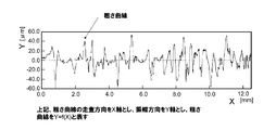
- the convex roller 51 cannot be expressed in a regular repeating pattern in at least one of the convex and concave shapes formed by the convex portions 511 and the concave portions 512 when measured in the rotation axis direction (X direction) and the circumferential direction of the convex roller 51. And has an uneven shape composed of random patterns.
- the roughness curve was measured using a contact-type roughness meter “SURFTEST SJ-210 (manufactured by Mitutoyo Corporation)”. Since the convex portion 511 of the convex roller 51 has a random pattern in the circumferential direction of the convex roller 51, the convex portion having a different height enters the nonwoven fabric 10 ′ at a random depth and scratches the fibers in the nonwoven fabric 10 ′. The long fibers in the nonwoven fabric 10 ′ are scratched at random positions in the thickness direction in the nonwoven fabric 10 ′, and a part thereof is broken.
- the bundled long fibers in the nonwoven fabric are randomly loosened in the thickness direction of the nonwoven fabric, and the touch feeling is greatly improved.
- the convex portion 511 enters the nonwoven fabric 10 ′ at a uniform depth and scratches the long fibers in the nonwoven fabric 10 ′, if the convex portion 511 is shallow, only the surface layer in the nonwoven fabric 10 ′ is loosened, and the touch feeling is improved.
- the protrusion 511 is deeply penetrated, the whole of the nonwoven fabric 10 'is loosened, but the long fibers 2 are also ruptured and broken, and the touch feeling is not improved.
- the convex part 511 of the convex roller 51 is also random in the rotation axis direction of the convex roller 51, the random pattern improves the touch more uniformly in the X direction (width direction) of the nonwoven fabric 10 ′. There is also an advantage of being able to.
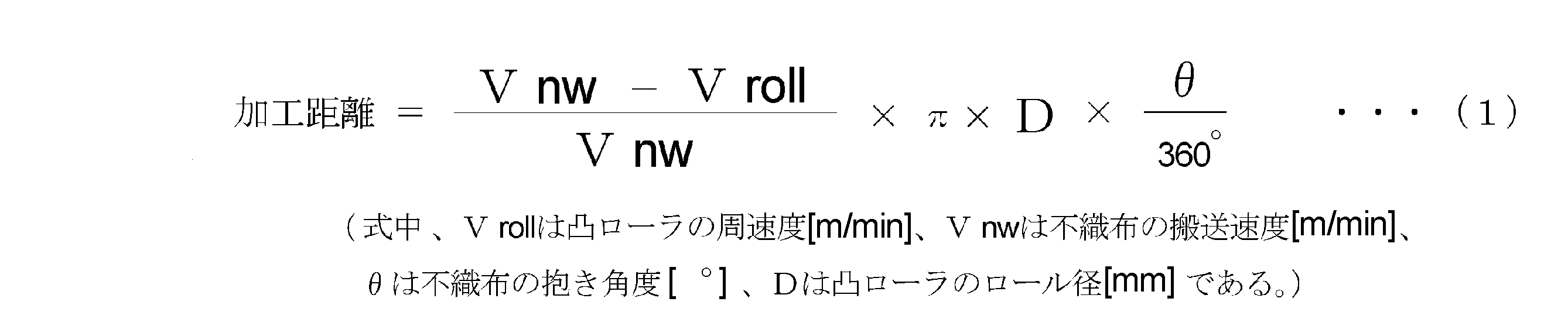
- the processing distance obtained by the following formula (1) is preferably 350 mm or more, more preferably 800 mm or more, and particularly preferably 1000 mm or more. It is preferably 10,000 mm or less, more preferably 5000 mm or less, specifically preferably 350 mm or more and 10,000 mm or less, and more preferably 1000 mm or more and 5000 mm or less.
- required by following formula (1) means the distance which the convex roller 51 and the nonwoven fabric contact
- the roller diameter of the convex roller 51 indicated by D is the diameter on the peripheral surface of the convex roller 51.
- a raw material nonwoven fabric 10 is used as a raw material for the nonwoven fabric 1.
- the raw material nonwoven fabric 10 include a spunbond nonwoven fabric and a laminated nonwoven fabric of a spunbond layer and a meltblown layer.
- the laminated nonwoven fabric include a spunbond-spunbond laminated nonwoven fabric and a spunbond-spunbond-spun layer. Examples thereof include bond laminated nonwoven fabric, spunbond-meltblown-spunbond laminated nonwoven fabric, and spunbond-spunbond-meltblown-spunbond laminated nonwoven fabric.
- the constituent fibers constituting the nonwoven fabric are made of a thermoplastic resin
- the thermoplastic resins include polyolefin resins, polyester resins, polyamide resins, acrylonitrile resins, vinyl resins. And vinylidene resins.
- the polyolefin resin include polyethylene, polypropylene, and polybuden.
- the polyester resin include polyethylene terephthalate and polybutylene terephthalate. Nylon etc. are mentioned as a polyamide-type resin.
- the vinyl resin include polyvinyl chloride.
- the vinylidene resin include polyvinylidene chloride. Modified products and mixtures of these various resins can also be used.
- thermoplastic resins polyolefin resins are particularly preferably used from the viewpoints of cost and touch.
- the fineness of the constituent fibers is preferably 0.5 dtex or more and 5 dtex or less, and more preferably 1 dtex or more and 3 dtex or less.
- the basis weight of the raw material nonwoven fabric 10 is preferably 5 g / m 2 or more and 50 g / m 2 or less, and more preferably 8 g / m 2 or more and 25 g / m 2 or less.
- the number of the heat-sealed portions is preferably 10 pieces / cm 2 or more and 250 pieces / cm 2 or less, and more preferably 35 pieces / cm 2 or more and 65 pieces / cm 2 or less.
- the shape of the heat fusion part is not particularly limited, and may be any shape such as a circle, a rhombus, and a triangle.
- the ratio of the total area of the heat-sealed portion to the surface area of one surface of the raw material nonwoven fabric 10 is preferably 3% to 50%, and more preferably 5% to 30%.
- the raw material nonwoven fabric 10 is heat-processed at the temperature below melting
- first, partial stretching is performed on each of a plurality of locations of the raw material nonwoven fabric 10 at a temperature of 50 ° C. or lower.
- the belt-shaped raw material nonwoven fabric 10 is unwound from a raw roll (not shown), and the raw material nonwoven fabric 10 is steel-matched embossed roller via conveying rollers 44 and 45 as shown in FIG.
- the raw material nonwoven fabric 10 is partially stretched by being conveyed between a pair of rollers 41 and 42. More specifically, the conveyed raw material nonwoven fabric 10 is moved between a plurality of convex portions 411 of one roller 41 and a plurality of concave portions 422 of the other roller 42 shown in FIGS. 6 and 7.
- the pressing force is further applied between the plurality of convex portions 421 of the other roller 42 and the plurality of concave portions 412 of the one roller 41, so that the conveying direction and the conveying direction are respectively applied to a plurality of locations of the raw material nonwoven fabric 10.
- Stretching is performed in a direction perpendicular to In this way, by performing stretching in the transport direction and the direction orthogonal to the transport direction, it is possible to suppress the decrease in breaking strength of the manufactured nonwoven fabric 1 by direction.
- the temperature of 50 ° C. or lower means that the temperature is not normal when the rollers 41 and 42 are not actively heated and the raw nonwoven fabric 10 is stretched.
- the melting point of any kind of constituent fiber resin from the viewpoint that the raw nonwoven fabric 10 does not become hard by causing heat fusion between the constituent fibers of the nonwoven fabric. Means a lower temperature.
- the direction orthogonal to the conveyance direction is the same direction as the rotation axis direction of the roller described above.
- raising treatment for raising the constituent fibers of the raw material nonwoven fabric 10 is applied to the raw material nonwoven fabric 10 ′ that has been subjected to the partial stretching processing.
- the raw material nonwoven fabric 10 ′ is conveyed to the convex roller 51 via the conveyance rollers 52 and 53.
- the convex roller 51 which has the convex part 511 in a surrounding surface
- a part of long fiber 2 which comprises the raw material nonwoven fabric 10 is fractured
- the nonwoven fabric 1 having the fibers 20 fixed by the heat fusion part 3 is continuously manufactured (see FIGS. 1 and 2).
- the rotation direction of the convex roller 51 is preferably rotated at a speed not less than 0.3 times and not more than 10 times the conveying speed of the raw material nonwoven fabric 10 ′. Further, when rotating in the circumferential direction (forward direction with respect to the conveying direction), it is preferable to rotate the convex roller 51 at a speed of 1.5 times or more and 20 times or less.
- the speed of the convex roller 51 means the peripheral speed on the peripheral surface of the convex roller 51.
- the surface (back surface) is different from the surface of the raw material nonwoven fabric 10 ′ processed by the convex roller 51. Is further processed by another convex roller 51.
- the nonwoven fabric manufactured by the suitable manufacturing method of the nonwoven fabric 1 mentioned above forms the weakening point in the heat-fusion part 3 with the steel matching embossing roller 43, and raises with the convex roller 51, it is manufactured with the conventional raising method. It is characterized in that the proportion of the loop-like fibers 21 is smaller than that of the non-woven fabric. Further, since the weakening point is formed in the heat-bonding portion 3 by the steel matching embossing roller 43 and the raised roller 51 is raised, so-called breaks (fissures, holes) are hardly formed between the heat-bonding portions 3, and the raw material nonwoven fabric 10 The breaking strength of can be maintained as it is.
- ruptured and only the one end part 20a is being fixed by the heat-fusion part 3 is formed.
- the part (refer FIG. 3) located between the heat-fusion parts 3 and 3 adjacent to the orientation direction (Y direction) of the long fiber 2 is with respect to the tensile load of 1 cN / 1mm.
- the elongation is 40% or more. Therefore, despite the high breaking strength, there is a feeling of plumpness as a whole, and the touch feeling when touched first is further improved.
- the spunbond nonwoven fabric or the spunbond laminated nonwoven fabric used as the raw material nonwoven fabric 10 has less plumpness in the past and is inferior to the touch compared to the nonwoven fabric of the air-through manufacturing method. Smoothness and plumpness have been added to greatly improve the touch. Moreover, according to the manufacturing method of the nonwoven fabric 1 of this embodiment, although the breaking strength is high as described above, the nonwoven fabric 1 has an overall plump feeling and further improved the touch feeling when first touched. Can be manufactured continuously.
- the range of use of the nonwoven fabric 1 is suitably used mainly for components in absorbent articles such as disposable diapers and sanitary napkins.
- the constituent member include a surface sheet, a back sheet, a sheet constituting an outer packaging material of the disposable diaper, and the nonwoven fabric 1 is particularly suitable for a surface sheet of an absorbent article used for a wearer's skin contact surface. Used for.
- the use range of the nonwoven fabric 1 is also suitably used for a cleaning sheet.
- the disposable diaper using the nonwoven fabric 1 will be described as an example.
- the pants-type disposable diaper 100 is positioned on the non-skin contact surface side of the absorbent main body 50 including the absorbent body 40 and fixes the absorbent main body 50.
- the outer packaging material 60 is provided.
- the absorbent main body 50 includes a liquid-permeable top sheet 70, a liquid-impermeable (including water-repellent) back sheet 80, and a liquid-retaining property interposed between both sheets 70 and 80. It has the absorber 40 and is substantially vertically long as shown in FIG.
- the outer packaging material 60 includes a back side portion A disposed on the back side of the wearer, an abdominal side portion B disposed on the abdomen side, and an inseam located between the crotch portions.
- the outer packaging material 60 includes an outer layer sheet 62 that forms the outer surface of the diaper, and an inner layer sheet 61 that is located on the skin contact surface side and is partially joined to the outer layer sheet 62.
- the waist elastic member 63 and the leg elastic member 64 for gathering are disposed between the sheets 61 and 62 in the waist and leg 6d that form the leg opening.
- the absorbent main body 50 is disposed across the back side portion A and the abdominal side portion B of the outer packaging material 60, and both end portions in the longitudinal direction of the absorbent main body 50 are disposed on the outer packaging material 60. It is in the position retreated inward in the longitudinal direction from both ends in the longitudinal direction.
- the absorbent main body 50 has a non-skin contact surface of the back sheet 80 of the absorbent main body 50 with an inner layer sheet 61 of the outer packaging material 60 by a bonding method using an adhesive, heat seal, ultrasonic seal or the like. It is joined to the skin contact surface.
- FIG. 14 the absorbent main body 50 has a non-skin contact surface of the back sheet 80 of the absorbent main body 50 with an inner layer sheet 61 of the outer packaging material 60 by a bonding method using an adhesive, heat seal, ultrasonic seal or the like. It is joined to the skin contact surface.
- side cuffs 55, 55 made of a liquid-impermeable or water-repellent and breathable material are provided on both sides along the longitudinal direction of the absorbent main body 50.
- an elastic member 56 for forming the side cuff is disposed and fixed in an extended state.
- the side cuff 55 can stand on the free end side when the diaper is worn, and can prevent excrement from flowing out in the width direction of the absorbent main body 50.
- the side cuff 55 forming sheet has a portion 55 a having a predetermined width on the outer side in the width direction of the absorbent main body 50 wound around the non-skin contact surface side of the absorbent body 40. 40 and the back sheet 80 are fixed. Note that the portion 55 a having a predetermined width may be fixed between the back sheet 30 and the outer packaging material 60.
- the nonwoven fabric 1 of this embodiment is preferably used as the outer layer sheet 62 and the inner layer sheet 61 of the outer packaging material 60 of the pants-type disposable diaper 100 used on the skin contact surface of the wearer. Moreover, it can also be used as the surface sheet 70, the back surface sheet 80, and the side cuff 55 forming sheet. As the member of each part when the nonwoven fabric 1 is not used, those used for absorbent articles such as disposable diapers can be used without particular limitation. For example, as the top sheet 70, a liquid-permeable nonwoven fabric, a perforated film, or a laminate thereof can be used, and as the back sheet 80, a resin film or a laminate of the resin film and the nonwoven fabric can be used. Can do.
- a stretchable film, a nonwoven fabric, a woven fabric, or a laminated sheet thereof can be used.
- a nonwoven fabric a nonwoven fabric, or a laminated sheet thereof
- a water-repellent nonwoven fabric or the like can be used.
- the absorber 40 those conventionally used for absorbent articles such as disposable diapers can be used without particular limitation.
- the absorbent body 40 a fiber aggregate of a fiber material such as pulp or a material in which a superabsorbent polymer is supported and wrapped with a covering material such as tissue paper or a water-permeable nonwoven fabric is used.
- a covering material such as tissue paper or a water-permeable nonwoven fabric.
- the elastic member 56 for forming side cuffs, the waist elastic member 63, and the leg elastic member 64 those normally used for absorbent articles such as disposable diapers can be used without particular limitation.
- a stretchable material made of natural rubber, polyurethane, polystyrene-polyisoprene copolymer, polystyrene-polybutadiene copolymer, polyethylene- ⁇ -olefin copolymer such as ethyl acrylate-ethylene, or the like can be used.
- the nonwoven fabric of this invention is not restrict
- the manufacturing method of the nonwoven fabric of this invention is not restrict
- the raw material nonwoven fabric 10 is subjected to a partial stretching process, other than using the raw material nonwoven fabric 10 that is heat-treated at a temperature lower than the melting point of the fiber that is configured in a separate step.
- the heat treatment may be performed at a temperature lower than the melting point of the fibers constituting the raw material nonwoven fabric 10.
- a hot air treatment unit is provided on the upstream side of the partial stretching unit 4, and the raw nonwoven fabric 10 heat-treated by the hot air processing unit is continuously steel-matched in the partial stretching unit 4. It may be conveyed between the pair of rollers 41 and 42 of the embossing roller 43 and subjected to partial stretching.
- the portion located between the heat fusion portions adjacent to each other in the orientation direction of the long fibers preferably has an elongation of 40% or more with respect to a tensile load of 1 cN / 1 mm, and further an elongation of 50% or more.
- the degree of elongation is preferably 60% or more, more preferably 200% or less, and further preferably 150% or less, particularly 120% or less.
- the nonwoven fabric according to ⁇ 1> preferably having a degree of elongation of.
- ⁇ 3> The nonwoven fabric according to ⁇ 1> or ⁇ 2>, wherein the nonwoven fabric preferably has a breaking strength value of 5.00 N / 50 mm or more and 8 N / 50 mm or more and 30 N / 50 mm or less.
- the ratio of the breaking strength of the raw material nonwoven fabric before breaking a part of the nonwoven fabric and the long fibers (breaking strength of the nonwoven fabric / breaking strength of the raw material nonwoven fabric) is 0.5 or more, preferably 0.7 or more, and 1
- the nonwoven fabric preferably has a bulk softness of 4.5 cN or less, more preferably 3 cN or less, still more preferably 2.5 cN or less, and preferably 0.5 cN or more.
- the compression characteristic value at the time of the minute load is preferably 14.7 (cN / cm 2 ) / mm (15 (gf / cm 2 ) / mm) or less, preferably 11.8 (cN / cm 2 ) / mm ( 12 (gf / cm 2 ) / mm) or less, more preferably 10.8 (cN / cm 2 ) / mm (11 (gf / cm 2 ) / mm) or less, ⁇
- the nonwoven fabric according to any one of 1> to ⁇ 4>.
- the amount of the raised fiber including the fiber in which only one end is fixed by the heat fusion part is preferably 10 / cm or more, and more preferably 15 / cm or more. 50 / cm or less, and the height is preferably 0.7 mm or more, more preferably 2.0 mm or more, preferably 5 mm or less, and 3 mm or less. More preferably, the nonwoven fabric according to any one of the above items ⁇ 1> to ⁇ 5>. ⁇ 7> The non-woven fabric before breaking a part of the long fibers preferably has a bulk softness of 10 cN or less, more preferably 6 cN or less, and preferably 1 cN or more. The nonwoven fabric according to any one of ⁇ 6>.
- ⁇ 8> The non-woven fabric according to any one of ⁇ 1> to ⁇ 7>, wherein the non-woven fabric before breaking a part of the long fibers is heat-treated at a temperature lower than the melting point of the fibers constituting the non-woven fabric.
- a method for producing a nonwoven fabric wherein a part of the nonwoven fabric is partially stretched at a temperature of 50 ° C. or less, and the nonwoven fabric subjected to the partial stretching process is subjected to raising to raise the constituent fibers of the nonwoven fabric,
- the raising process is performed using a convex roller having a plurality of convex portions on the peripheral surface, In the convex roller, in at least one of the rotation axis direction and the circumferential direction, the convex portions are arranged in a random pattern,
- the convex roller is a method for producing a nonwoven fabric in which a processing distance obtained by the following formula (1) is 350 mm or more.
- ⁇ 10> The method for producing a nonwoven fabric according to ⁇ 9>, wherein the convex portions of the convex roller are arranged in a random pattern in the circumferential direction of the convex roller in the raising process.
- ⁇ 11> The method for producing a nonwoven fabric according to ⁇ 9> or ⁇ 10>, wherein the raised portions of the raised roller are arranged in a random pattern in the direction of the rotation axis of the raised roller in the raising process.
- the processing distance is preferably 350 mm or more, more preferably 800 mm or more, and particularly preferably 1000 mm or more.
- the method for producing a nonwoven fabric according to any one of ⁇ 9> to ⁇ 11> preferably 10,000 mm or less, and more preferably 5000 mm or less.
- the rotation direction of the convex roller is rotated in the direction opposite to the conveying direction of the raw material nonwoven fabric, and the convex roller is rotated at a speed of 0.3 to 10 times the conveying speed of the raw material nonwoven fabric.
- the partial stretching process is performed using a pair of concave and convex rollers, One roller has a plurality of convex portions on the peripheral surface, and the other roller has a concave portion into which the convex portion enters the peripheral surface at a position corresponding to the convex portion of the one roller.
- the meshing depth between the convex portion of one of the rollers and the convex portion of the other roller is preferably 3.5 mm or more, more preferably 4 mm or more and 10 mm or less, and 4 mm or more and 6 mm or less.
- the area of the top surfaces of the convex portions of the pair of concavo-convex rollers is preferably 1 mm 2 or more and 100 mm 2 or less, more preferably 4 mm 2 or more and 25 mm 2 or less, ⁇ 14> The manufacturing method of the nonwoven fabric as described.
- the height h 1 of the convex portions of the first concave and convex rollers constituting the pair of concave and convex rollers is different from the height h 2 of the convex portions of the second concave and convex rollers.
- ⁇ 18> The partial stretching is performed by pressing between a plurality of convex portions of one roller and a plurality of concave portions of the other roller, and further, a plurality of convex portions of the other roller and one roller.
- ⁇ 14> to ⁇ 17> wherein the material is sandwiched between a plurality of concave portions and stretched in each of a plurality of locations of the raw material nonwoven fabric in the transport direction and in a direction perpendicular to the transport direction.
- Manufacturing method of non-woven fabric ⁇ 19> The method for producing a nonwoven fabric according to any one of ⁇ 9> to ⁇ 18>, wherein a nonwoven fabric having a bulk softness of 10 cN or less is used as the raw material nonwoven fabric.
- ⁇ 20> The method for producing a nonwoven fabric according to any one of ⁇ 9> to ⁇ 19>, wherein the raw nonwoven fabric is subjected to a heat treatment at a temperature lower than the melting point of the fibers constituting the raw nonwoven fabric before the partial stretching process.
- ⁇ 21> An absorbent article using the nonwoven fabric according to any one of ⁇ 1> to ⁇ 8> as a constituent member.
- ⁇ 22> A disposable diaper using the nonwoven fabric according to any one of ⁇ 1> to ⁇ 8> as a constituent member.
- Example 1 A spunbonded nonwoven fabric having a basis weight of 18 g / m 2 , a thickness of 0.29 mm, and a bulk density of 16.1 g / cm 3 made of polypropylene resin having a fiber diameter of 16 ⁇ m was used as the raw material nonwoven fabric.
- the bulk softness of the raw material nonwoven fabric measured based on the above-described bulk softness measurement method was 7.6 cN.
- this spunbonded nonwoven fabric is partially stretched through a steel matching embossing roller 43 shown in FIGS. 6 and 7, and further raised by a convex roller 51 in which convex portions 511 shown in FIG. 11 are arranged in a random pattern. And the nonwoven fabric of Example 1 was produced.
- each convex portion 411 of the roller 41 and each convex portion 421 of the roller 42 was 4 mm.
- the height of the convex part 411 is 5 mm
- the distance (pitch P 1 ) between the convex parts 411 adjacent in the circumferential direction is 8.5 mm
- the distance (pitch P) between the convex parts 411 adjacent in the rotation axis direction. 2 ) was 8.5 mm.
- Each convex part 421 in the roller 42 of the steel matching embossing roller 43 is the same.
- required by Formula (1) mentioned above was 2435 mm.
- Example 2 The same raw material nonwoven fabric as in Example 1 is used, and a two-step process is performed under the same conditions as in Example 1 except that the convex roller 51 having a processing distance of 864 mm determined by the above-described formula (1) is used. A non-woven fabric was prepared.
- Example 3 The same raw material nonwoven fabric as in Example 1 is used, and a two-step process is performed under the same conditions as in Example 1 except that the convex roller 51 having a processing distance of 393 mm determined by the above-described formula (1) is used. A non-woven fabric was prepared.
- Example 4 Using a spunbonded nonwoven fabric having a basis weight of 17 g / m 2 , a thickness of 0.26 mm, and a bulk density of 15.3 g / cm 3 made of polypropylene resin having a fiber diameter of 16 ⁇ m as the raw material nonwoven fabric, the processing required by the above formula (1) A nonwoven fabric of Example 4 was produced by performing two-stage treatment under the same conditions as in Example 1 except that the convex roller 51 having a distance of 370 mm was used. In addition, the bulk softness of the raw material nonwoven fabric measured based on the above-described bulk softness measurement method was 4.2 cN.
- Example 5 As a raw material nonwoven fabric, a spunbond nonwoven fabric having a basis weight of 18 g / m 2 , a thickness of 0.27 mm, and a bulk density of 15.0 g / cm 3 made of a polypropylene resin having a fiber diameter of 18 ⁇ m is used, and the processing required by the above-described formula (1) A nonwoven fabric of Example 5 was produced by performing two-stage treatment under the same conditions as in Example 1 except that the convex roller 51 having a distance of 707 mm was used. In addition, the bulk softness of the raw material nonwoven fabric measured based on the above-described bulk softness measurement method was 10 cN.
- Comparative Example 1 The same raw material nonwoven fabric as in Example 1 was used.
- As the steel matching embossing roller for performing the partial stretching process a pair of rollers having a meshing depth of 3 mm between each convex portion of one roller and each convex portion of the other roller was used.
- the convex roller to which the raising process is performed the convex portions are arranged in a regular pattern, and the processing distance obtained by the above-described formula (1) is 393 mm. Otherwise, the nonwoven fabric of Comparative Example 1 was produced by performing two-stage treatment under the same conditions as in Example 1.
- Example 2 The raw material nonwoven fabric used in Example 1 was used as the nonwoven fabric of Comparative Example 2. The nonwoven fabric of Comparative Example 2 was not particularly subjected to partial stretching or raising.
- the breaking strength is high, the whole has a plump feeling, and the touch feeling when touched first is improved.
- the method for producing a nonwoven fabric of the present invention it is possible to continuously produce a nonwoven fabric having an overall feeling of fluff and improved touch feeling when first touched even though the breaking strength is high. .
Landscapes
- Engineering & Computer Science (AREA)
- Textile Engineering (AREA)
- Health & Medical Sciences (AREA)
- Vascular Medicine (AREA)
- Biomedical Technology (AREA)
- Heart & Thoracic Surgery (AREA)
- Epidemiology (AREA)
- Life Sciences & Earth Sciences (AREA)
- Animal Behavior & Ethology (AREA)
- General Health & Medical Sciences (AREA)
- Public Health (AREA)
- Veterinary Medicine (AREA)
- Treatment Of Fiber Materials (AREA)
- Nonwoven Fabrics (AREA)
- Absorbent Articles And Supports Therefor (AREA)
Abstract
Description

本実施形態の不織布1は、図1に示すように、長繊維2を含むウェブを熱融着部3により固定した不織布であって、長繊維2の一部が破断されて、一端部20aのみが熱融着部3により固定されている繊維20を備えている。不織布1については、図1に示すように、不織布1の長手方向をY方向、不織布1の幅方向をX方向として、以下説明する。尚、不織布1に関し、構成繊維の配向方向により繊維の配向方向に沿うMD方向を長手方向(Y方向)、それと直交するCD方向を幅方向(X方向)と判断する。従って、以下の説明では、Y方向とMD方向とは同じ方向を意味し、X方向とCD方向は同じ方向を意味する。
22℃65%RH環境下にて、不織布1又は原料不織布10から、X方向に5mm、配向方向(Y方向)に50mm以上の寸法の長方形形状の測定片を切り出す。この切り出された長方形形状の測定片の中央領域にあるY方向に隣り合う2個の熱融着部3,3を選出する。次に、図3に示すように、選出した熱融着部3,3どうしの間に位置する部分、言い換えれば、選出した2個の熱融着部3,3で挟まれた領域Tの不織布の伸度を測定するために、2個の熱融着部3,3のY方向の中間位置にて、前記長方形形状の測定片のY方向に沿う両側縁それぞれから領域TのY方向に沿う両側縁それぞれの位置まで、X方向に延びる切り込みを入れて測定サンプルを作製する。この測定サンプルを、Y方向が引張方向となるように、引張試験機(例えば、オリエンテック社製テンシロン引張り試験機「RTA-100」)のチャックに取り付ける。チャック間距離は25mmとする。測定サンプルを50mm/分で引っ張り、幅1mmに対して1cN/1mmの引張荷重をかけた際の伸度(%)を測定する。尚、伸度(%)は、設定した上記チャック間距離に対する、伸長されて増加した分の長さの割合であり、例えば、設定した上記チャック間距離25mmのサンプルが50mmに伸長した場合、その伸度(%)は{(50-25)/25}×100=100%とされる。
22℃65%RH環境下にて、不織布1又は原料不織布10から、X方向(幅方向)に200mm、Y方向(長手方向)に50mmの寸法の長方形形状の測定片を切り出す。この切り出された長方形形状の測定片を測定サンプルとする。この測定サンプルを、X方向が引張方向となるように、引張試験機(例えば、オリエンテック社製テンシロン引張り試験機「RTA-100」)のチャックに取り付ける。チャック間距離は150mmとする。測定サンプルを300mm/分で引っ張り、サンプル破断までの最大荷重点をX方向の破断強度とする。また、Y方向に200mm、X方向に50mmの寸法の長方形形状の測定片を切り出し、これを測定サンプルとする。この測定サンプルを、そのY方向が引張方向となるように引張試験機のチャックに取り付ける。上述したX方向の破断強度の測定方法と同様の手順によってY方向の破断強度を求める。
尚、原料不織布10は、そのバルクソフトネスが、柔軟なものが得られ肌触りに優れる観点から、10cN以下であることが好ましく、6cN以下であることが更に好ましく、そして1cN以上であることが好ましく、具体的には、0.5cN以上10cN以下であることが好ましく、1cN以上8cN以下であることが更に好ましい。
バルクソフトネスは、以下の測定法により測定する。
不織布1のバルクソフトネスは、22℃65%RH環境下にて、不織布1をY方向(長手方向)に150mm、X方向(幅方向)に30mm切り出し、直径45mmのリング状に、ホッチキスを用いて端部を上下2箇所で止める。このときステープラーの芯はY方向(長手方向)に長くなるようにする。引張試験機(例えば、オリエンテック社製テンシロン引張り試験機「RTA-100」)を用いて、試料台の上に前記リングを筒状に立て、上方から台とほぼ平行な平板にて圧縮速度10mm/分の速度で圧縮していった際の最大荷重を測定し、バルクスフトネスとする。
微小荷重時の圧縮特性値の算出の元となるデータの測定はカトーテック株式会社製のKES FB3-AUTO-A(商品名)を用い、22℃65%RH環境下にて測定を行う。具体的には、不織布1を20cm×20cmに3枚カットして測定サンプルを準備する。次にそのうちの1枚の測定サンプルを試験台に起毛面を上に向けて設置する(起毛してない場合、または両面が起毛している場合は両方測定して小さいほうを採用する)。次に、面積2cm2の円形平面の鋼板間で圧縮する。圧縮速度20μm/sec、最大圧縮荷重9.80cN/cm2(10.0gf/cm2)、回復過程も同一速度で測定する。このとき、鋼板間の変位量をx(mm)とし、荷重をy(cN/cm2)とし、荷重を検知した点の位置をx=0として圧縮方向に測定する。xの値は圧縮されるほど大きくなる。
図4は、22℃65%RH環境下にて、不織布1を構成する繊維の中で起毛している繊維の量を測定する方法を示した模式図である。先ず、測定する不織布から、鋭利なかみそりで、20cm×20cmの測定片を切り出し、図4(a)に示すように、測定片の起毛した面において、複数個の熱融着部3を通るX方向に延びる折り返し線Zにて山折りして測定サンプル104を形成する。次に、この測定サンプル104を、A4サイズの黒い台紙の上に載せ、図4(b)に示すように、さらにその上に、縦1cm×横1cmの穴107をあけたA4サイズの黒い台紙を載せる。このとき、図4(b)に示すように、測定サンプル104の折り目105が、上側の黒い台紙の穴107から見えるように配置する。両台紙には、富士共和製紙株式会社の「ケンラン(黒)連量265g」を用いた。その後、上側の台紙の穴107の両側それぞれから、折り目105に沿って外方に5cm離れた位置に、50gのおもりをそれぞれ載せ、測定サンプル104が完全に折りたたまれた状態を作る。次に、図4(c)に示すように、マイクロスコープ(KEYENCE社製VHX-900)を用いて、30倍の倍率で、台紙の穴107内を観察し、測定サンプル104の折り目105から0.2mm上方に平行移動した位置に形成される仮想線108よりも上方に起毛している1cmあたりの起毛した繊維の本数を計測する。9箇所計測し、平均値(少数第二位を四捨五入)を起毛している繊維の量とする。
凹凸ローラの頂部の面積の面積率(凹凸加工された領域の全体の面積に対する頂部の面積の割合)は第一ローラ、第二ローラともに4%以上20%以下、より好ましくは7%以上15%以下であると不織布の狭圧部ができずに肌触りがよく、かつ延伸倍率の高いものができる(面積率が小さいほど延伸倍率が高くなる)。
搬送方向の隙間の割合={〔(a-(b+c)〕/a}×100・・・(2)
ここで、aは二等分する位置d1/2での搬送方向(Y方向)に隣り合う第1凹凸ローラ41及び第2凹凸ローラ42の内の一方の凹凸ローラの凸部411,421のピッチ、bは二等分する位置d1/2での一方の凹凸ローラの凸部411,421の搬送方向(Y方向)の厚み、cは二等分する位置d1/2での他方の凹凸ローラの凸部421,411の搬送方向(Y方向)の厚みである。例えば、図8に示す製造装置200を用いて説明すると、aは二等分する位置d1/2での周方向に隣り合う第2凹凸ローラ42の凸部421のピッチ、bは二等分する位置d1/2での第2凹凸ローラ42の凸部421の搬送方向の厚み、cは二等分する位置d1/2での第1凹凸ローラ41の凸部421の搬送方向の厚みである。
なお、前記粗さ曲線は、接触式の粗さ計「SURFTEST SJ-210(株式会社ミツトヨ製)」を用いて測定した。
凸ローラ51の凸部511が凸ローラ51の周方向にランダムパターンであることによって、高さの異なる凸部が不織布10’にランダムな深さで入り込み不織布10’中の繊維を引っかくことになり、不織布10’中の厚み方向のランダムな位置で不織布10’中の長繊維を引っかき、その一部を破断する。不織布10’中の厚み方向のランダムな位置で不織布10’中の長繊維を引っかくことで、不織布の厚み方向において、ランダムに不織布中の束なった長繊維がほぐされタッチ感が大きく向上する。均一な深さで凸部511が不織布10’に入り込み不織布10’中の長繊維を引っかく場合、凸部511の入り込みが浅いと、不織布10’中の表層のみがほぐされタッチ感の向上は見られないし、また凸部511の入り込みが深い場合には、不織布10’中の全体がほぐされるが、長繊維2の破断も多くなり破れが生じ、タッチ感は向上しない。
さらに前記ランダムパターンは、凸ローラ51の凸部511が凸ローラ51の回転軸方向にもランダムである場合には、不織布10’のX方向(幅方向)に、より均一に肌触りを向上することができるというメリットもある。
尚、下記式(1)で求められる加工距離は、図12に示すように、凸ローラ51と不織布とが接している距離を意味する。また、Dで示す凸ローラ51のローラ径は、凸ローラ51の周面での直径である。
また、原料不織布10は、ふっくら感を高め、タッチ感を高める観点から、原料不織布10を構成する繊維の融点未満の温度で熱処理されていることが好ましく、特に熱風処理されていることが好ましい。
本実施形態の不織布1には、図1及び図2に示すように、長繊維2の一部が破断されて、一端部20aのみが熱融着部3により固定されている繊維20が形成されている。また、不織布1においては、長繊維2の配向方向(Y方向)に隣り合う熱融着部3,3どうしの間に位置する部分(図3参照)が、1cN/1mmの引張荷重に対して、40%以上の伸度である。その為、破断強度が高いにも拘わらず、全体にふっくら感があり、最初に触った際のタッチ感が更に向上する。原料不織布10として用いた、スパンボンド不織布やスパンボンドの積層不織布は、従来ふっくら感が少なく、エアスルー製法の不織布と比較して肌触りに劣るものであるが、上述した本実施形態の不織布1は、滑らかさに、ふっくらさが加わり肌触りが大きく向上している。
また、本実施態様の不織布1の製造方法によれば、前述したような、破断強度が高いにも拘わらず、全体にふっくら感があり、最初に触った際のタッチ感が更に向上した不織布1を連続して製造することができる。
吸収性本体50は、図14に示すように、液透過性の表面シート70、液不透過性(撥水性も含む)の裏面シート80及び両シート70,80間に介在された液保持性の吸収体40を有しており、図13に示すように、実質的に縦長である。
外包材60は、図13に示すように、着用者の背側に配される背側部A、腹側に配される腹側部B、それらの間に位置し股間部に配される股下部Cを有しており、背側部Aと腹側部Bの両側縁部6a,6b同士が接合されて、一対のサイドシール部(図示せず)、一対のレッグ開口部(図示せず)及びウエスト開口部(図示せず)が形成される。また、外包材60は、おむつの外面を形成する外層シート62、その肌当接面側に位置して部分的に該外層シート62と接合された内層シート61を有しており、ウエスト開口部及びレッグ開口部を形成するウエスト部及びレッグ部6dにおける両シート61,62間に、ギャザー形成用のウエスト部弾性部材63及びレッグ部弾性部材64が配されている。
吸収性本体50の長手方向に沿う両側部には、図14に示すように、液不透過性又は撥水性で且つ通気性の素材から構成された側方カフス55,55が設けられている。各側方カフス55の自由端部近傍には、側方カフス形成用の弾性部材56が伸長状態で配設固定されている。側方カフス55は、おむつの装着時に自由端部側が起立し、吸収性本体50の幅方向への排泄物の流出を阻止することができる。側方カフス55形成用シートは、図14に示すように、吸収性本体50の幅方向外方の所定幅の部分55aが、吸収体40の非肌当接面側に巻き込まれて、吸収体40と裏面シート80との間に固定されている。尚、所定幅の部分55aが、裏面シート30と外包材60との間に固定されていてもよい。
側方カフス形成用の弾性部材56、ウエスト部弾性部材63及びレッグ部弾性部材64としては、通常、使い捨ておむつ等の吸収性物品に用いられるもの等を、特に制限なく用いることができる。例えば、天然ゴム、ポリウレタン、ポリスチレン-ポリイソプレン共重合体、ポリスチレン-ポリブタジエン共重合体、アクリル酸エチル-エチレン等のポリエチレン-αオレフィン共重合体等からなる伸縮性の材料等を用いることができる。
また、本発明の不織布の製造方法は、上述の実施態様の製造方法に何ら制限されるものではなく、適宜変更可能である。
長繊維を含むウェブを熱融着部により固定した不織布であって、
前記長繊維の一部が破断されて、一端部のみが前記熱融着部により固定されている繊維を備えており、
前記長繊維の配向方向に隣り合う前記熱融着部どうしの間に位置する部分は、1cN/1mmの引張荷重に対して35%以上の伸度である不織布。
前記長繊維の配向方向に隣り合う前記熱融着部どうしの間に位置する部分は、1cN/1mmの引張荷重に対して40%以上の伸度であることが好ましく、更に50%以上の伸度であることが好ましく、特に60%以上の伸度であることが好ましく、そして200%以下の伸度であることが好ましく、更に150%以下の伸度であることが好ましく、特に120%以下の伸度であることが好ましい、前記<1>記載の不織布。
<3>
前記不織布は、破断強度の値が、5.00N/50mm以上であることが好ましく、8N/50mm以上30N/50mm以下である、前記<1>又は<2>記載の不織布。
<4>
前記不織布と前記長繊維の一部を破断する前の原料不織布の破断強度の比(不織布の破断強度/原料不織布の破断強度)が、0.5以上、好ましくは0.7以上、そして、1.0以下である、前記<1>~<3>の何れか1に記載の不織布。
<5>
前記不織布は、そのバルクソフトネスが4.5cN以下であることが好ましく、3cN以下であることがより好ましく、2.5cN以下であることが更に好ましく、そして0.5cN以上であることが好ましく、その微小荷重時の圧縮特性値が14.7(cN/cm2)/mm(15(gf/cm2)/mm)以下であることが好ましく、11.8(cN/cm2)/mm(12(gf/cm2)/mm)以下であることがより好ましく、10.8(cN/cm2)/mm(11(gf/cm2)/mm)以下であることがより好ましい、前記<1>~<4>の何れか1に記載の不織布。
<6>
一端部のみが前記熱融着部により固定されている前記繊維を含む起毛している繊維は、その量が10本/cm以上であることが好ましく、15本/cm以上であることが更に好ましく、50本/cm以下であることが好ましく、且つその高さが0.7mm以上であることが好ましく、2.0mm以上であることが更に好ましく、5mm以下であることが好ましく、3mm以下であることがさらに好ましい、前記<1>~<5>の何れか1に記載の不織布。
<7>
前記長繊維の一部を破断する前の不織布は、そのバルクソフトネスが10cN以下であることが好ましく、6cN以下であることが更に好ましく、そして1cN以上であることが好ましい、前記<1>~<6>の何れか1に記載の不織布。
<8>
前記長繊維の一部を破断する前の不織布は、その不織布を構成する繊維の融点未満の温度で熱処理されている、前記<1>~<7>の何れか1に記載の不織布。
50℃以下の温度で不織布の複数箇所それぞれに部分延伸加工を施し、該部分延伸加工の施された不織布に該不織布の構成繊維を起毛する起毛加工を施す不織布の製造方法であって、
前記起毛加工は、周面に複数個の凸部を有する凸ローラを用いて行い、
前記凸ローラは、回転軸方向および周方向の少なくとも何れか一方において、凸部がランダムパターンで配されており、
前記凸ローラは、下記式(1)で求められる加工距離が350mm以上である不織布の製造方法。
前記起毛加工における、前記凸ローラの凸部が凸ローラの周方向にランダムパターンで配されている、前記<9>記載の不織布の製造方法。
<11>
前記起毛加工における、前記凸ローラの凸部が凸ローラの回転軸方向にランダムパターンで配されている、前記<9>又は<10>記載の不織布の製造方法。
<12>
前記加工距離が、350mm以上であることが好ましく、800mm以上であることが更に好ましく、1000mm以上であることが殊更好ましい。そして10000mm以下であることが好ましく、5000mm以下であることが更に好ましい、前記<9>~<11>の何れか1に記載の不織布の製造方法。
<13>
前記起毛加工における、凸ローラの回転方向を、原料不織布の搬送方向に対して逆方向に回転させ、原料不織布の搬送速度に対し、0.3倍以上10倍以下の速度で前記凸ローラを回転させる、前記<9>~<12>の何れか1に記載の不織布の製造方法。
<14>
前記部分延伸加工は、一対の凹凸ローラを用いて行い、
一方のローラが周面に複数個の凸部を有し、他方のローラが周面に一方の前記ローラの前記凸部に対応する位置に該凸部が入り込む凹部を有しており、
一方の前記ローラの凸部と他方の前記ローラの凸部との噛み合い深さが、3.5mm以上であることが好ましく、4mm以上10mm以下であることが更に好ましく、4mm以上6mm以下であることが殊更好ましい、前記<9>~<13>の何れか1に記載の不織布の製造方法。
<15>
前記部分延伸加工における、一対の前記凹凸ローラの凸部の頂部表面の面積は、1mm2以上100mm2以下であることが好ましく、4mm2以上25mm2以下であることが更に好ましい、前記<14>記載の不織布の製造方法。
<16>
前記部分延伸加工における、一対の前記凹凸ローラを構成する第1凹凸ローラの凸部の高さh1と第2凹凸ローラの凸部の高さh2とが異なっており、第2凹凸ローラの凸部の方が第1凹凸ローラの凸部よりも高く形成されている、前記<14>又は<15>記載の不織布の製造方法。
<17>
前記第1凹凸ロール及び前記第2凹凸ロールを最大に噛み合わせたときに、噛み合わせ
の深さd0を二等分する位置d1/2にて平断面視すると、前記第1凹凸ロール及び第2凹凸ロールそれぞれの凸部の全周に亘って、好ましくは0.1mm以上10mm以下、より好ましくは0.6mm以上8mm以下、さらに好ましくは、0.8mm以上3mm以下の隙間が形成されている、前記<16>記載の不織布の製造方法。
<18>
前記部分延伸加工は、一方のローラの有する複数個の凸部と、他方のローラの有する複数個の凹部との間で挟圧し、さらに他方のローラの有する複数個の凸部と、一方のローラの有する複数個の凹部との間で挟圧して、原料不織布の複数箇所それぞれに搬送方向及び搬送方向に直交する方向に延伸加工を施す、前記<14>~<17>の何れか1に記載の不織布の製造方法。
<19>
原料不織布として、そのバルクソフトネスが10cN以下の不織布を用いる、前記<9>~<18>の何れか1に記載の不織布の製造方法。
<20>
前記部分延伸加工を施す前に、原料不織布に、該原料不織布を構成する繊維の融点未満の温度で熱処理を施す、前記<9>~<19>の何れか1に記載の不織布の製造方法。
前記<1>~<8>の何れか1に記載の不織布を構成部材として用いた吸収性物品。
<22>
前記<1>~<8>の何れか1に記載の不織布を構成部材として用いた使い捨ておむつ。
原料不織布として、繊維径16μmのポリプロピレン樹脂からなる坪量18g/m2、厚み0.29mm、嵩密度16.1g/cm3のスパンボンド不織布を使用した。尚、上述したバルクソフトネスの測定方法に基づいて測定した原料不織布のバルクソフトネスは7.6cNであった。次に、このスパンボンド不織布を、図6及び図7に示すスチールマッチングエンボスローラ43に通して部分延伸加工し、更に図11に示す凸部511がランダムパターンで配された凸ローラ51により起毛加工して実施例1の不織布を作製した。用いたスチールマッチングエンボスローラ43におけるローラ41の各凸部411とローラ42の各凸部421との噛み合いの深さは4mmであった。また凸部411の高さが5mmであり、周方向に隣り合う凸部411同士の距離(ピッチP1)は8.5mmであり、回転軸方向に隣り合う凸部411同士の距離(ピッチP2)は8.5mmであった。スチールマッチングエンボスローラ43のローラ42における各凸部421も同じである。また、上述した式(1)で求められる加工距離が2435mmであった。
実施例1と同じ原料不織布を使用し、上述した式(1)で求められる加工距離が864mmである凸ローラ51を用いる以外は、実施例1と同様の条件で二段階処理して実施例2の不織布を作製した。
実施例1と同じ原料不織布を使用し、上述した式(1)で求められる加工距離が393mmである凸ローラ51を用いる以外は、実施例1と同様の条件で二段階処理して実施例3の不織布を作製した。
原料不織布として、繊維径16μmのポリプロピレン樹脂からなる坪量17g/m2、厚み0.26mm、嵩密度15.3g/cm3のスパンボンド不織布を使用し、上述した式(1)で求められる加工距離が370mmである凸ローラ51を用いる以外は、実施例1と同様の条件で二段階処理して実施例4の不織布を作製した。尚、上述したバルクソフトネスの測定方法に基づいて測定した原料不織布のバルクソフトネスは4.2cNであった。
原料不織布として、繊維径18μmのポリプロピレン樹脂からなる坪量18g/m2、厚み0.27mm、嵩密度15.0g/cm3のスパンボンド不織布を使用し、上述した式(1)で求められる加工距離が707mmである凸ローラ51を用いる以外は、実施例1と同様の条件で二段階処理して実施例5の不織布を作製した。尚、上述したバルクソフトネスの測定方法に基づいて測定した原料不織布のバルクソフトネスは10cNであった。
実施例1と同じ原料不織布を使用した。部分延伸加工を施すスチールマッチングエンボスローラとしては、一方のローラの各凸部と他方のローラの各凸部との噛み合いの深さは3mmである一対のローラを用いた。起毛加工を施す凸ローラは凸部が規則的なパターンで配されており、上述した式(1)で求められる加工距離が393mmであった。それ以外は、実施例1と同様の条件で二段階処理して比較例1の不織布を作製した。
実施例1に用いた原料不織布を比較例2の不織布とした。比較例2の不織布は、特に部分延伸加工も起毛加工も行わなかった。
実施例1~3、比較例1~2の不織布について、定法により坪量、厚み及び嵩密度を測定すると共に、上述した方法に従って、熱融着部どうしの間に位置する部分の伸度、破断強度、バルクソフトネス、微小荷重時の圧縮特性値、起毛している繊維の量、起毛している繊維の高さを測定した。また、実施例1~3、比較例1~2の不織布について、後述する方法に従って、肌触り性及びタッチ感をそれぞれ評価した。評価環境は室温20℃、湿度60%RHであった。それらの結果を下記表1に示す。
上述した熱融着部どうしの間に位置する部分の伸度の測定法に基づいて、実施例1~3、比較例1~2の不織布における熱融着部どうしの間に位置する部分の伸度を測定した。
実施例1~3、比較例1~2で得られた不織布について、元の不織布を基準(1点)としたときの5段階の(5点に近づく程よりよい肌触り)官能評価を5人に対して行い、各不織布について1人につき3枚行い、その全ての値の平均値を、整数桁に四捨五入して求め、表1に示した。なお、本評価は図15に示すように、各不織布を揉むように触ったときの官能評価である。
実施例1~3、比較例1~2で得られた不織布について、元の不織布を基準(1点)としたときの5段階の(5点に近づく程よりよい肌触り)官能評価を5人に対して行い、各不織布について1人につき3枚行い、その全ての値の平均値を、整数桁に四捨五入して求め、表1に示した。なお、本評価は図16に示すように、各不織布に軽くタッチするように触ったときの官能評価である。

また、本発明の不織布の製造方法によれば、破断強度が高いにも拘わらず、全体にふっくら感があり、最初に触った際のタッチ感が向上した不織布を連続して製造することができる。
Claims (22)
- 長繊維を含むウェブを熱融着部により固定した不織布であって、
前記長繊維の一部が破断されて、一端部のみが前記熱融着部により固定されている繊維を備えており、
前記長繊維の配向方向に隣り合う前記熱融着部どうしの間に位置する部分は、1cN/1mmの引張荷重に対して35%以上の伸度である不織布。 - 前記長繊維の配向方向に隣り合う前記熱融着部どうしの間に位置する部分は、1cN/1mmの引張荷重に対して40%以上の伸度であるか、50%以上の伸度であるか、又は60%以上の伸度であり、そして200%以下の伸度であるか、150%以下の伸度であるか、又は120%以下の伸度である請求項1に記載の不織布。
- 前記不織布は、破断強度の値が、5.00N/50mm以上、又は8N/50mm以上30N/50mm以下である請求項1又は2に記載の不織布。
- 前記不織布と前記長繊維の一部を破断する前の原料不織布の破断強度の比(不織布の破断強度/原料不織布の破断強度)が、0.5以上、又は0.7以上、そして、1.0以下である請求項1~3の何れか1項に記載の不織布。
- 前記不織布は、そのバルクソフトネスが4.5cN以下であるか、3cN以下であるか、又は2.5cN以下であり、そして0.5cN以上であり、その微小荷重時の圧縮特性値が14.7(cN/cm2)/mm(15(gf/cm2)/mm)以下であるか、11.8(cN/cm2)/mm(12(gf/cm2)/mm)以下であるか、又は10.8(cN/cm2)/mm(11(gf/cm2)/mm)以下である請求項1~4の何れか1項に記載の不織布。
- 一端部のみが前記熱融着部により固定されている前記繊維を含む起毛している繊維は、その量が10本/cm以上、又は15本/cm以上であり、そして、50本/cm以下であり、且つその高さが0.7mm以上、又は2.0mm以上であり、そして、5mm以下、又は3mm以下である請求項1~5の何れか1項に記載の不織布。
- 前記長繊維の一部を破断する前の不織布は、そのバルクソフトネスが10cN以下、又は6cN以下であり、そして、1cN以上である請求項1~6の何れか1項に記載の不織布。
- 前記長繊維の一部を破断する前の不織布は、その不織布を構成する繊維の融点未満の温度で熱処理されている、請求項1~7の何れか1項に記載の不織布。
- 50℃以下の温度で不織布の複数箇所それぞれに部分延伸加工を施し、該部分延伸加工の施された不織布に該不織布の構成繊維を起毛する起毛加工を施す不織布の製造方法であって、
前記起毛加工は、周面に複数個の凸部を有する凸ローラを用いて行い、
前記凸ローラは、回転軸方向および周方向の少なくとも何れか一方において、凸部がランダムパターンで配されており、
前記凸ローラは、下記式(1)で求められる加工距離が350mm以上である不織布の製造方法。

- 前記起毛加工における、前記凸ローラの凸部が凸ローラの周方向にランダムパターンで配されている、請求項9に記載の不織布の製造方法。
- 前記起毛加工における、前記凸ローラの凸部が凸ローラの回転軸方向にランダムパターンで配されている、請求項9又は10に記載の不織布の製造方法。
- 前記加工距離が、350mm以上、800mm以上、又は1000mm以上であり、そして、10000mm以下、又は5000mm以下である請求項9~11の何れか1項に記載の不織布の製造方法。
- 前記起毛加工における、凸ローラの回転方向を、原料不織布の搬送方向に対して逆方向に回転させ、原料不織布の搬送速度に対し、0.3倍以上10倍以下の速度で前記凸ローラを回転させる、請求項9~12の何れか1項に記載の不織布の製造方法。
- 前記部分延伸加工は、一対の凹凸ローラを用いて行い、
一方のローラが周面に複数個の凸部を有し、他方のローラが周面に一方の前記ローラの前記凸部に対応する位置に該凸部が入り込む凹部を有しており、
一方の前記ローラの凸部と他方の前記ローラの凸部との噛み合い深さが、3.5mm以上、そして、4mm以上10mm以下であるか、又は4mm以上6mm以下である請求項9~13の何れか1項に記載の不織布の製造方法。 - 前記部分延伸加工における、一対の前記凹凸ローラの凸部の頂部表面の面積は、1mm2以上100mm2以下であるか、又は4mm2以上25mm2以下である請求項14に記載の不織布の製造方法。
- 前記部分延伸加工における、一対の前記凹凸ローラを構成する第1凹凸ローラの凸部の高さh1と第2凹凸ローラの凸部の高さh2とが異なっており、第2凹凸ローラの凸部の方が第1凹凸ローラの凸部よりも高く形成されている、請求項14又は15に記載の不織布の製造方法。
- 前記第1凹凸ロール及び前記第2凹凸ロールを最大に噛み合わせたときに、噛み合わせ
の深さd0を二等分する位置d1/2にて平断面視すると、前記第1凹凸ロール及び第2凹凸ロールそれぞれの凸部の全周に亘って、0.1mm以上10mm以下、0.6mm以上8mm以下、又は0.8mm以上3mm以下の隙間が形成されている請求項16に記載の不織布の製造方法。 - 前記部分延伸加工は、一方のローラの有する複数個の凸部と、他方のローラの有する複数個の凹部との間で挟圧し、さらに他方のローラの有する複数個の凸部と、一方のローラの有する複数個の凹部との間で挟圧して、原料不織布の複数箇所それぞれに搬送方向及び搬送方向に直交する方向に延伸加工を施す、請求項14~17の何れか1項に記載の不織布の製造方法。
- 原料不織布として、そのバルクソフトネスが10cN以下の不織布を用いる、請求項9~18の何れか1項に記載の不織布の製造方法。
- 前記部分延伸加工を施す前に、原料不織布に、該原料不織布を構成する繊維の融点未満の温度で熱処理を施す、請求項9~19の何れか1項に記載の不織布の製造方法。
- 請求項1~8の何れか1項に記載の不織布を構成部材として用いた吸収性物品。
- 請求項1~8の何れか1項に記載の不織布を構成部材として用いた使い捨ておむつ。
Priority Applications (2)
| Application Number | Priority Date | Filing Date | Title |
|---|---|---|---|
| CN201380019918.4A CN104220662B (zh) | 2012-12-19 | 2013-11-28 | 无纺布及其制造方法 |
| RU2014141376/12A RU2558905C1 (ru) | 2012-12-19 | 2013-11-28 | Нетканый материал и способ его изготовления |
Applications Claiming Priority (4)
| Application Number | Priority Date | Filing Date | Title |
|---|---|---|---|
| JP2012276679 | 2012-12-19 | ||
| JP2012-276679 | 2012-12-19 | ||
| JP2013235917A JP5514948B1 (ja) | 2012-12-19 | 2013-11-14 | 不織布及びその製造方法 |
| JP2013-235917 | 2013-11-14 |
Publications (1)
| Publication Number | Publication Date |
|---|---|
| WO2014097839A1 true WO2014097839A1 (ja) | 2014-06-26 |
Family
ID=50978180
Family Applications (1)
| Application Number | Title | Priority Date | Filing Date |
|---|---|---|---|
| PCT/JP2013/081995 Ceased WO2014097839A1 (ja) | 2012-12-19 | 2013-11-28 | 不織布及びその製造方法 |
Country Status (4)
| Country | Link |
|---|---|
| JP (1) | JP5514948B1 (ja) |
| CN (1) | CN104220662B (ja) |
| RU (1) | RU2558905C1 (ja) |
| WO (1) | WO2014097839A1 (ja) |
Cited By (2)
| Publication number | Priority date | Publication date | Assignee | Title |
|---|---|---|---|---|
| JP2020014747A (ja) * | 2018-07-27 | 2020-01-30 | 日本製紙クレシア株式会社 | 不織布ワイパーおよびその製造方法 |
| CN113230032A (zh) * | 2021-04-26 | 2021-08-10 | 嘉兴学院 | 一种复合芯体及其制备方法 |
Families Citing this family (4)
| Publication number | Priority date | Publication date | Assignee | Title |
|---|---|---|---|---|
| JP6546435B2 (ja) * | 2015-04-14 | 2019-07-17 | 花王株式会社 | 不織布の製造方法 |
| CN104988660B (zh) * | 2015-06-18 | 2019-01-25 | 厦门延江新材料股份有限公司 | 一种立体热风无纺布生产方法 |
| CN108048979B (zh) * | 2018-02-13 | 2023-03-14 | 盐城工业职业技术学院 | 一种基于高压静电蓬化和热定型原理的人造羽绒生产设备 |
| CN112593375A (zh) * | 2020-12-23 | 2021-04-02 | 李小刚 | 一种新一代智能制造无纺布喷绒质量揉搓检验设备 |
Citations (3)
| Publication number | Priority date | Publication date | Assignee | Title |
|---|---|---|---|---|
| JPH1072757A (ja) * | 1996-08-21 | 1998-03-17 | Mitsui Petrochem Ind Ltd | 清拭材用不織布およびその製造方法 |
| JP2002302861A (ja) * | 2001-04-09 | 2002-10-18 | Chisso Corp | 起毛様不織布、その製造法及びそれを用いた繊維製品 |
| WO2012042972A1 (ja) * | 2010-09-30 | 2012-04-05 | 花王株式会社 | 不織布及び不織布の製造方法 |
Family Cites Families (8)
| Publication number | Priority date | Publication date | Assignee | Title |
|---|---|---|---|---|
| JPH11318791A (ja) * | 1998-05-18 | 1999-11-24 | Uni Charm Corp | 起毛させた拭き取りシート及びその製造方法並びにこの拭き取りシートを用いた清掃用物品 |
| JP4338578B2 (ja) * | 2004-04-28 | 2009-10-07 | 花王株式会社 | 嵩高シート及びその製造方法 |
| JP4742819B2 (ja) * | 2005-11-08 | 2011-08-10 | 東レ株式会社 | ワイピングクロスおよびその製造方法 |
| US7803244B2 (en) * | 2006-08-31 | 2010-09-28 | Kimberly-Clark Worldwide, Inc. | Nonwoven composite containing an apertured elastic film |
| JP5099752B2 (ja) * | 2007-05-24 | 2012-12-19 | 花王株式会社 | 表面シートの製造方法 |
| JP4975089B2 (ja) * | 2008-12-25 | 2012-07-11 | 花王株式会社 | 不織布及びその製造方法 |
| CN101974829A (zh) * | 2010-08-27 | 2011-02-16 | 山东俊富非织造材料有限公司 | 物理改性非织造布及其制造方法 |
| US20120238170A1 (en) * | 2011-03-15 | 2012-09-20 | Paul Thomas Weisman | Fluid Permeable Structured Fibrous Web |
-
2013
- 2013-11-14 JP JP2013235917A patent/JP5514948B1/ja active Active
- 2013-11-28 CN CN201380019918.4A patent/CN104220662B/zh active Active
- 2013-11-28 WO PCT/JP2013/081995 patent/WO2014097839A1/ja not_active Ceased
- 2013-11-28 RU RU2014141376/12A patent/RU2558905C1/ru active
Patent Citations (3)
| Publication number | Priority date | Publication date | Assignee | Title |
|---|---|---|---|---|
| JPH1072757A (ja) * | 1996-08-21 | 1998-03-17 | Mitsui Petrochem Ind Ltd | 清拭材用不織布およびその製造方法 |
| JP2002302861A (ja) * | 2001-04-09 | 2002-10-18 | Chisso Corp | 起毛様不織布、その製造法及びそれを用いた繊維製品 |
| WO2012042972A1 (ja) * | 2010-09-30 | 2012-04-05 | 花王株式会社 | 不織布及び不織布の製造方法 |
Cited By (4)
| Publication number | Priority date | Publication date | Assignee | Title |
|---|---|---|---|---|
| JP2020014747A (ja) * | 2018-07-27 | 2020-01-30 | 日本製紙クレシア株式会社 | 不織布ワイパーおよびその製造方法 |
| JP7128682B2 (ja) | 2018-07-27 | 2022-08-31 | 日本製紙クレシア株式会社 | 不織布ワイパーおよびその製造方法 |
| CN113230032A (zh) * | 2021-04-26 | 2021-08-10 | 嘉兴学院 | 一种复合芯体及其制备方法 |
| CN113230032B (zh) * | 2021-04-26 | 2022-07-12 | 嘉兴学院 | 一种复合芯体及其制备方法 |
Also Published As
| Publication number | Publication date |
|---|---|
| RU2558905C1 (ru) | 2015-08-10 |
| JP5514948B1 (ja) | 2014-06-04 |
| CN104220662A (zh) | 2014-12-17 |
| CN104220662B (zh) | 2017-06-13 |
| JP2014139358A (ja) | 2014-07-31 |
Similar Documents
| Publication | Publication Date | Title |
|---|---|---|
| JP6099030B2 (ja) | 吸収性物品 | |
| JP5514948B1 (ja) | 不織布及びその製造方法 | |
| CN108348374B (zh) | 吸收性物品 | |
| JP5622921B2 (ja) | 不織布 | |
| JP4982615B2 (ja) | 不織布 | |
| EP2623657A1 (en) | Non-woven fabric and method for producing non-woven fabric | |
| JP6326222B2 (ja) | 使い捨てパンツ型おむつ | |
| JP6442181B2 (ja) | パンツ型使い捨ておむつ | |
| JP5989988B2 (ja) | 吸収性物品 | |
| WO2016013448A1 (ja) | パンツ型使い捨ておむつ | |
| JP5530023B1 (ja) | 不織布 | |
| JP4889439B2 (ja) | 伸縮性不織布 | |
| JP6170822B2 (ja) | 不織布及びその製造方法 | |
| JP5779011B2 (ja) | 吸収性物品 | |
| JP7319042B2 (ja) | 複合伸縮シートの製造方法 | |
| JP2015104605A (ja) | 使い捨てパンツ型おむつ | |
| JP6283208B2 (ja) | 使い捨てパンツ型おむつ | |
| JP2015104607A (ja) | 使い捨てパンツ型おむつ | |
| JP6538410B2 (ja) | 不織布及びその製造方法 | |
| JP7572913B2 (ja) | 吸収性物品 | |
| JP3214474U (ja) | 使い捨てパンツ型おむつ | |
| JP6546435B2 (ja) | 不織布の製造方法 | |
| JP7319041B2 (ja) | 吸収性物品用複合伸縮シート、それを有する吸収性物品、及びその製造方法 | |
| JP6355254B2 (ja) | 繊維積層体の製造方法及び繊維積層体 |
Legal Events
| Date | Code | Title | Description |
|---|---|---|---|
| 121 | Ep: the epo has been informed by wipo that ep was designated in this application |
Ref document number: 13865056 Country of ref document: EP Kind code of ref document: A1 |
|
| WWE | Wipo information: entry into national phase |
Ref document number: IDP00201405280 Country of ref document: ID |
|
| ENP | Entry into the national phase |
Ref document number: 2014141376 Country of ref document: RU Kind code of ref document: A |
|
| NENP | Non-entry into the national phase |
Ref country code: DE |
|
| 122 | Ep: pct application non-entry in european phase |
Ref document number: 13865056 Country of ref document: EP Kind code of ref document: A1 |