WO2014087592A1 - 原料気化供給装置 - Google Patents
原料気化供給装置 Download PDFInfo
- Publication number
- WO2014087592A1 WO2014087592A1 PCT/JP2013/006812 JP2013006812W WO2014087592A1 WO 2014087592 A1 WO2014087592 A1 WO 2014087592A1 JP 2013006812 W JP2013006812 W JP 2013006812W WO 2014087592 A1 WO2014087592 A1 WO 2014087592A1
- Authority
- WO
- WIPO (PCT)
- Prior art keywords
- raw material
- control device
- gas
- flow rate
- receiving tank
- Prior art date
Links
Images


Classifications
-
- C—CHEMISTRY; METALLURGY
- C23—COATING METALLIC MATERIAL; COATING MATERIAL WITH METALLIC MATERIAL; CHEMICAL SURFACE TREATMENT; DIFFUSION TREATMENT OF METALLIC MATERIAL; COATING BY VACUUM EVAPORATION, BY SPUTTERING, BY ION IMPLANTATION OR BY CHEMICAL VAPOUR DEPOSITION, IN GENERAL; INHIBITING CORROSION OF METALLIC MATERIAL OR INCRUSTATION IN GENERAL
- C23C—COATING METALLIC MATERIAL; COATING MATERIAL WITH METALLIC MATERIAL; SURFACE TREATMENT OF METALLIC MATERIAL BY DIFFUSION INTO THE SURFACE, BY CHEMICAL CONVERSION OR SUBSTITUTION; COATING BY VACUUM EVAPORATION, BY SPUTTERING, BY ION IMPLANTATION OR BY CHEMICAL VAPOUR DEPOSITION, IN GENERAL
- C23C16/00—Chemical coating by decomposition of gaseous compounds, without leaving reaction products of surface material in the coating, i.e. chemical vapour deposition [CVD] processes
- C23C16/44—Chemical coating by decomposition of gaseous compounds, without leaving reaction products of surface material in the coating, i.e. chemical vapour deposition [CVD] processes characterised by the method of coating
- C23C16/448—Chemical coating by decomposition of gaseous compounds, without leaving reaction products of surface material in the coating, i.e. chemical vapour deposition [CVD] processes characterised by the method of coating characterised by the method used for generating reactive gas streams, e.g. by evaporation or sublimation of precursor materials
- C23C16/4481—Chemical coating by decomposition of gaseous compounds, without leaving reaction products of surface material in the coating, i.e. chemical vapour deposition [CVD] processes characterised by the method of coating characterised by the method used for generating reactive gas streams, e.g. by evaporation or sublimation of precursor materials by evaporation using carrier gas in contact with the source material
- C23C16/4482—Chemical coating by decomposition of gaseous compounds, without leaving reaction products of surface material in the coating, i.e. chemical vapour deposition [CVD] processes characterised by the method of coating characterised by the method used for generating reactive gas streams, e.g. by evaporation or sublimation of precursor materials by evaporation using carrier gas in contact with the source material by bubbling of carrier gas through liquid source material
-
- C—CHEMISTRY; METALLURGY
- C23—COATING METALLIC MATERIAL; COATING MATERIAL WITH METALLIC MATERIAL; CHEMICAL SURFACE TREATMENT; DIFFUSION TREATMENT OF METALLIC MATERIAL; COATING BY VACUUM EVAPORATION, BY SPUTTERING, BY ION IMPLANTATION OR BY CHEMICAL VAPOUR DEPOSITION, IN GENERAL; INHIBITING CORROSION OF METALLIC MATERIAL OR INCRUSTATION IN GENERAL
- C23C—COATING METALLIC MATERIAL; COATING MATERIAL WITH METALLIC MATERIAL; SURFACE TREATMENT OF METALLIC MATERIAL BY DIFFUSION INTO THE SURFACE, BY CHEMICAL CONVERSION OR SUBSTITUTION; COATING BY VACUUM EVAPORATION, BY SPUTTERING, BY ION IMPLANTATION OR BY CHEMICAL VAPOUR DEPOSITION, IN GENERAL
- C23C16/00—Chemical coating by decomposition of gaseous compounds, without leaving reaction products of surface material in the coating, i.e. chemical vapour deposition [CVD] processes
- C23C16/44—Chemical coating by decomposition of gaseous compounds, without leaving reaction products of surface material in the coating, i.e. chemical vapour deposition [CVD] processes characterised by the method of coating
- C23C16/448—Chemical coating by decomposition of gaseous compounds, without leaving reaction products of surface material in the coating, i.e. chemical vapour deposition [CVD] processes characterised by the method of coating characterised by the method used for generating reactive gas streams, e.g. by evaporation or sublimation of precursor materials
- C23C16/4485—Chemical coating by decomposition of gaseous compounds, without leaving reaction products of surface material in the coating, i.e. chemical vapour deposition [CVD] processes characterised by the method of coating characterised by the method used for generating reactive gas streams, e.g. by evaporation or sublimation of precursor materials by evaporation without using carrier gas in contact with the source material
-
- C—CHEMISTRY; METALLURGY
- C23—COATING METALLIC MATERIAL; COATING MATERIAL WITH METALLIC MATERIAL; CHEMICAL SURFACE TREATMENT; DIFFUSION TREATMENT OF METALLIC MATERIAL; COATING BY VACUUM EVAPORATION, BY SPUTTERING, BY ION IMPLANTATION OR BY CHEMICAL VAPOUR DEPOSITION, IN GENERAL; INHIBITING CORROSION OF METALLIC MATERIAL OR INCRUSTATION IN GENERAL
- C23C—COATING METALLIC MATERIAL; COATING MATERIAL WITH METALLIC MATERIAL; SURFACE TREATMENT OF METALLIC MATERIAL BY DIFFUSION INTO THE SURFACE, BY CHEMICAL CONVERSION OR SUBSTITUTION; COATING BY VACUUM EVAPORATION, BY SPUTTERING, BY ION IMPLANTATION OR BY CHEMICAL VAPOUR DEPOSITION, IN GENERAL
- C23C16/00—Chemical coating by decomposition of gaseous compounds, without leaving reaction products of surface material in the coating, i.e. chemical vapour deposition [CVD] processes
- C23C16/44—Chemical coating by decomposition of gaseous compounds, without leaving reaction products of surface material in the coating, i.e. chemical vapour deposition [CVD] processes characterised by the method of coating
- C23C16/52—Controlling or regulating the coating process
-
- F—MECHANICAL ENGINEERING; LIGHTING; HEATING; WEAPONS; BLASTING
- F17—STORING OR DISTRIBUTING GASES OR LIQUIDS
- F17C—VESSELS FOR CONTAINING OR STORING COMPRESSED, LIQUEFIED OR SOLIDIFIED GASES; FIXED-CAPACITY GAS-HOLDERS; FILLING VESSELS WITH, OR DISCHARGING FROM VESSELS, COMPRESSED, LIQUEFIED, OR SOLIDIFIED GASES
- F17C9/00—Methods or apparatus for discharging liquefied or solidified gases from vessels not under pressure
- F17C9/02—Methods or apparatus for discharging liquefied or solidified gases from vessels not under pressure with change of state, e.g. vaporisation
-
- F—MECHANICAL ENGINEERING; LIGHTING; HEATING; WEAPONS; BLASTING
- F22—STEAM GENERATION
- F22B—METHODS OF STEAM GENERATION; STEAM BOILERS
- F22B1/00—Methods of steam generation characterised by form of heating method
- F22B1/28—Methods of steam generation characterised by form of heating method in boilers heated electrically
- F22B1/284—Methods of steam generation characterised by form of heating method in boilers heated electrically with water in reservoirs
- F22B1/285—Methods of steam generation characterised by form of heating method in boilers heated electrically with water in reservoirs the water being fed by a pump to the reservoirs
Definitions
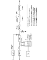
- MFC 1 to MFC 3 are calorific mass flow controllers
- TC is a tank temperature controller
- T is a raw material receiving tank
- PR is a tank internal pressure controller
- RTU is a reactor tube (test sample)
- FT-IR Is an infrared spectrophotometer
- the raw material receiving tank T is filled with dimethyl zinc (DMZn, saturated vapor pressure 15 Torr at 24 ° C.).
- DMZn dimethyl zinc
- the temperature in the vicinity of the reactor tube RTU and FT-IR is adjusted to a temperature of 100 to 700 ° C. by a heating device.
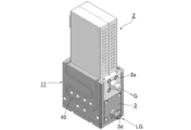
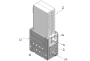
- the vaporizer 1 heats the inside of the vaporization chamber 3, the vaporization chamber 3 having a plurality of compartments (three chambers in the embodiment), a vaporization promoting block body (not shown) provided in each chamber, and the vaporization chamber 3.
- a heating device (not shown) is provided, and the vaporized source gas G flows into the high-temperature pressure flow control device 2 from the gas outlet 3e.
- a block body and a heating device are provided in each chamber of the vaporization chamber 3, but each chamber of the vaporization chamber 3 can be a vacant chamber.
- the high-temperature pressure type flow rate control device 2 is a well-known device, and the device main body 2a is adjustable in temperature by a heating device (not shown).
- 22 is a downstream stop valve, and 23 is a source gas outlet.
- the wetted parts and / or the wetted parts made of stainless steel (SUS316L), Hastelloy C22 and Spron 100 are all subjected to Al 2 O 3 passivation treatment and have an average thickness of 20 nm.
- a film mainly composed of Al 2 O 3 is uniformly formed on the entire wetted part and / or the wetted part.
- Al 2 O 3 passivation treatment is performed, but Cr 2 O 3 passivation treatment may be performed instead. In some cases, it is also possible to perform Al 2 O 3 passivation treatment on some devices and Cr 2 O 3 passivation treatment on other devices.
- FIG. 4 is a block configuration diagram of the raw material vaporization supply apparatus according to the second embodiment, and the configuration of the raw material vaporization supply apparatus is the same as the apparatus shown in FIGS.
- the pressure detector of the high-temperature pressure flow controller 2 is a Hastelloy C22
- the diaphragm constituting the valve body of the high-temperature pressure flow controller 2 is a spron 100.
- the gas installation part and the liquid contact part of the equipment are all formed of stainless steel (SUS316L).
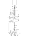
- FIG. 7 is a block diagram of the raw material vaporization supply apparatus according to the third embodiment, and the configuration of the raw material vaporization supply apparatus is the same as that shown in FIG.
- the pressure detector of the high-temperature pressure-type flow control device 2 is a Hastelloy C22
- the diaphragm constituting the valve body part of the high-temperature-type pressure-type flow control device 2 is a spron 100.
- the gas contact part and the liquid contact part of the devices are all formed of stainless steel (SUS316L).
Abstract
Description
しかし、このバブリング方式は、供給する原料ガスの流量制御や原料ガスの濃度制御、原料ガスの蒸気圧等の点に多くの問題があり、これ等の問題を解決するものとして、本願発明者等は先に、圧力式流量制御装置により原料ガスの流量制御を行うようにした気化器方式の原料気化供給装置(特開2009-252760号)を公開している。
また、本願発明者等は、上記気化器方式と平行して、圧力式流量制御装置により原料ガスの流量制御を行うようにしたベーキング方式の原料気化供給装置(特開2013-33782号、特開2012-234860号等)の開発を進めている。
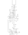
尚、図9に於いて、Mは加熱温度制御装置、V1は液体供給量制御弁、Lはリリーフ弁、Gpは原料受入タンク加圧用ガス、LGは原料液体、Gは原料ガス、To~T1は温度検出器、V2~V7は開閉弁、P0~P1は圧力検出器、3は気化チャンバ、4は脈動低減用オリフィス、5は液溜部、7,8は流路、9はバッファータンクである。
同様に、気化器1の加熱温度検出器Toからの信号によって加熱温度制御装置Mを介して加熱装置6aのヒータへの入力や液体供給量制御弁V1の開度調整が行われ、前記液体供給量制御装置Qと加熱温度制御装置Mとによって、高温型圧力式流量制御装置2の上流側ガス圧が所望の圧力値以上となるように制御される。
尚、図12に於いて、14は原料液体供給口、15はパージガス供給口、16は希釈ガス供給口、17は他の薄膜形成用ガス供給口、18,19,20は流路、V8~V16はバルブである。
尚、原料ガスGの流路等のパージはパージガス供給口15からN2等のパージガスGpを供給することにより、また、ヘリウムやアルゴン、水素等の希釈ガスG1は、希釈ガス供給口16から必要に応じて供給される。更に、原料ガスGの流路は恒温加熱装置12により40℃~220℃に加熱されており、原料ガスGが再凝縮することはない。
また、高温圧力式流量制御装置2の使用により、マスフローコントローラ(熱式質量流量制御装置)のような原料ガスGの凝縮による詰まりが皆無となり、熱式質量流量制御装置を用いた原料気化供給装置よりも安定した原料ガスGの供給ができる。
更に、原料受入タンクT内の原料蒸気G0の蒸気圧が若干変動しても、高精度な流量制御ができること、原料気化供給装置の大幅な小型化と製造コストの引下げが出来ること等の優れた効用が得られる。
先ず、第1の問題は原料ガスGの熱分解の問題である。一般に、半導体のプロセス処理装置においては、管路途中に於けるプロセスガスの再凝縮の防止やプロセス処理効率の観点から、より高い蒸気圧の高純度原料ガスGの安定供給が望まれている。具体的には、200kPa abs.程度の高蒸気圧を求められるケースが存在するが、200kPa abs.の蒸気圧を得るには、原料ガスGを相当の高温度に加熱する必要があり、例えば、原料ガスがTEOSの場合には200℃に、TEBの場合には150℃に、TMInの場合には150℃に、DEZnの場合には140℃に、TiCl4の場合には160℃に、夫々加熱、保持する必要がある。
しかし、従来のこの種不働態処理技術は、ガス温度が100~120℃以下の低温ガスを取り扱う管路や機器類を対象とするものであり、150℃を超える高温度の有機金属原料ガスを取り扱う管路や機器類に対しては、不働態処理を施すことによる原料ガスの熱分解防止効果等に付いての解析が十分に行なわれていないと言う問題がある。
特に、ステンレス鋼との接触により、低温度で熱分解を起こすジエチル亜鉛(DEZn)のような原料ガスであっても、Al2O3不働態処理をすることにより110℃近傍まで加熱することが出来、高い圧力の原料ガス供給が可能となる。
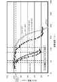
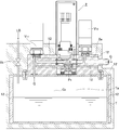
本願発明者等は、先ず、半導体製造用に使用される各種の有機金属材料(以下MO原料と呼ぶ)の熱分解特性を評価するため、図1の如き試験装置を製作し、これを用いて、金属表面及びその温度と、これに接触する各種のMO原料ガスの熱分解開始温度の関係を調査した。尚、試験に供した金属は、ステンレス鋼(SUS316L)とスプロン(100)とハステロイ(C22)の3種類である。
尚、図示されてはいないが、リアクターチューブRTU及びFT-IRの近傍は加熱装置により100~700℃の温度に調節されている。
また、リアクターチューブRTUとしては、(1)SUS316L製6.35mmφ×1000mm、(2)ハステロイC22製6.35mmφ×1000mm、(3)Al2O3不働態表面を有する12.7mmφのSUS316L製管内にスプロン100の試験片を入れたもの、(4)上記(1)の内表面にAl2O3不働態処理を施したもの、及び(5)上記(1)の内表面にCr2O3不働態処理を施したもの、の5種類の試験体を製作し、これをリアクターチューブRTUとして用いた。
また、表1には、合成樹脂材(ポリイミド樹脂PI及び4フッ化エチレン樹脂PFA)製の試験片について行なった試験結果も記載している。これは、一部の機器類の接ガス部、例えば、圧力式流量制御装置の上流側や下流側に設置するバルブのバルブシートやシール材等に、合成樹脂材が使用されることがあるからである。

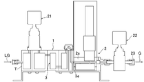
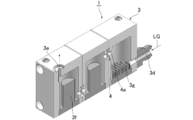
図3は、本願発明の第1実施例を示すものであり、当該原料気化供給装置は、原料受入タンクTと液供給用バルブ21と気化器1と高温型圧力式流量制御装置2等から構成されており、原料受入タンクTと気化器1の間に液供給用バルブ21が設けられている。また、原料受入タンクTには加熱装置(図示省略)が設けられている。
尚、上記気化器1では、気化チャンバ3の各室内にブロック体や加熱装置を設けるようにしているが、気化チャンバ3の各室を単なる空室とすることも可能である。
尚、図3において、22は下流側ストップバルブ、23は原料ガス出口である。
尚、第1実施例では、Al2O3不働態処理を施しているが、此れに代えてCr2O3不働態処理を施してもよい。また、場合によっては、一部の機器類にAl2O3不働態処理を、その他の機器類にCr2O3不働態処理を施すことも可能である。
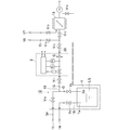
図4は、第2実施例に係る原料気化供給装置のブロック構成図であり、原料気化供給装置の構成は、従前の図9~図11に示した装置と同じである同様である。
また、当該第2実施例においても、高温型圧力式流量制御装置2の圧力検出器をハステロイC22により、また、高温型圧力式流量制御装置2の弁体部を構成するダイヤフラムをスプロン100により、更に、給液バルブ21及び下流側ストップバルブ22のバルブシートをPFAにより夫々形成している点を除いて、バルブ本体や気化器1、流路を構成する部材、流量制御装置本体2a等の各機器類の設ガス部及び接液部は、全てステンレス鋼(SUS316L)により形成されている。
また、原料気化供給装置そのものの作動は従前の図9~図11の場合と同様であるため、ここではその説明を省略する。
図7は、第3実施例に係る原料気化供給装置のブロック構成図であり、原料気化供給装置の構成は、前記図12に示したものと同様である。
また、当該第3実施例においても、高温型圧力式流量制御装置2の圧力検出器をハステロイC22により、また、高温型圧力式流量制御装置2の弁体部を構成するダイヤフラムをスプロン100により、更に、給液バルブ21及び下流側ストップバルブ22のバルブシートをPFAにより夫々形成している点を除いて、バルブ本体や気化器1、流路を構成する部材、流量制御装置本体2a等の各機器類の接ガス部及び接液部は、全てステンレス鋼(SUS316L)により形成されている。
また、原料気化供給装置そのものの作動は前記図12の場合と同様であるため、ここではその説明を省略する。
Ta タンク内部の上方空間
LG 原料液体(MO材料)
G 原料ガス
Go 原料蒸気(飽和蒸気)
Gp 原料受入タンク加圧用ガス
PG パージガス
MFC1~MFC3 熱量式質量流量制御装置(マスフローコントローラ)
V1 液体供給量制御弁
V2~V7 開閉弁
Q 液体供給量制御装置
M 加熱温度制御装置
L リリーフ弁
To~T1 温度検出器
Po~P1 圧力検出器
Tc タンク温度調節装置
Pr 圧力調整装置
RTU リアクターチューブ
FT-IR 赤外分光光度計
1 気化器
2 高温型圧力式流量制御装置
2a 流量制御装置本体
2b ピエゾ駆動部
2c 断熱用シャフト
3 気化チャンバ
3d 液体入口
3e ガス出口
3f~3g 加熱促進体
4 脈動低減用オリフィス
4a 通孔
5 液溜部
6(6a~6c) 加熱装置
7 流路
8(8a~8b) 流路
9 バッファータンク
10 ヒータ
11 加熱板
12 恒温加熱装置
13 プロセスチャンバ
14 原料液体供給口
15 パージガス供給口
16 希釈ガス供給口
17 薄膜形成用ガス供給口
18 流路
19 流路
20 流路
21 給液バルブ
22 下流側ストップバルブ
23 原料ガス出口
Claims (12)
- 原料受入タンクと、原料受入タンクから圧送されてきた液体を気化する気化器と、気化器からの原料ガスの流量を調整する流量制御装置と、気化器と流量制御装置とこれ等に接続された流路の所望部分を加熱する加熱装置とを備える原料気化供給装置であって、少なくとも前記原料受入タンクと気化器と流量制御装置と前記各機器装置間を連結する流路と該流路に介設した開閉弁バルブのいずれかの金属表面の各接液部又は接ガス部に、不働態処理を施したことを特徴とする原料気化供給装置。
- 原料を貯留した原料受入タンクと、原料受入タンクへ原料を供給する流路と、原料受入タンクの内部空間部から原料ガスをプロセスチャンバへ供給する原料ガス流路と、プロセスチャンバへ供給する原料ガス流量を制御する流量制御装置と、原料受入タンクと原料ガス流路と流量制御装置とを設定温度に加熱する恒温加熱装置とを備える原料気化供給装置であって、少なくとも前記原料受入タンクと流量制御装置と前記各機器装置間を連結する流路と該流路に介設した開閉弁のいずれかの金属表面の各接液部又は接ガス部に、不働態処理を施したことを特徴とする原料気化供給装置。
- 金属表面の各接液部又は接ガス部に施す不働態処理が、Al2O3不働態処理又はCr2O3不働態処理又はFeF2不働態処理であることを特徴とする請求項1又は請求項2に記載の原料気化供給装置。
- 流量制御装置が、高温型圧力式流量制御装置であることを特徴とする請求項1又は請求項2に記載の原料気化供給装置。
- 気化器の気化チャンバの上方に流量制御装置の装置本体を搭載する構成とした請求項1に記載の原料気化供給装置。
- 流量制御装置の上流側のガス圧力が予め定めた設定圧力以上となるように、原料受入れタンクから気化器へ圧送する液体量を調整する液体供給制御装置を備えた構成とした請求項1に記載の原料気化供給装置。
- 流量制御装置の上流側圧力が予め定めた設定圧力以上となるように、気化器の加熱温度を調整する温度制御装置を備えた構成とした請求項1に記載の原料気化供給装置。
- パージガス供給路を流量制御装置の一次側へ分岐状に連結すると共に希釈ガス供給路を流量制御装置の二次側へ分岐状に連結するようにした請求項2に記載の原料気化供給装置。
- 接液部又は接ガス部の金属をステンレス鋼(SUS316L)、ハステロイ(C22),スプロン(100)の何れか、また、接液部又は接ガス部を形成する合成樹脂材として4フッ化エチレン樹脂(PFA)を、更に金属外表面の不働態処理としてAl2O3不働態処理を夫々使用するようにした請求項1又は請求項2に記載の原料気化供給装置。
- 圧力検出器の接液部又は接ガス部をハステロイ(C22)製に、バルブ類のシートを4フッ化エチレン樹脂(PFA)製に、流量制御装置のコントロール弁のダイヤフラムをスプロン(100)製に、流路及びその他の機器類の構成部材をステンレス鋼(SUS316L)製に夫々した請求項9に記載の原料気化供給装置。
- 流量制御装置からの原料ガス(但し、ジエチル亜鉛(DEZn)の原料ガスを除く)の加熱温度を、蒸気圧が200kPa abs以下となる温度とした請求項9に記載の原料気化供給装置。
- 流量制御装置からの原料ガスGをジエチル亜鉛(DEZn)としてその加熱温度を105℃以下とするようにした請求項9に記載の原料気化供給装置。
Priority Applications (3)
| Application Number | Priority Date | Filing Date | Title |
|---|---|---|---|
| CN201380057690.8A CN104822858B (zh) | 2012-12-06 | 2013-11-20 | 原料气化供给装置 |
| KR1020157003850A KR101613141B1 (ko) | 2012-12-06 | 2013-11-20 | 원료 기화 공급 장치 |
| US14/650,496 US9994955B2 (en) | 2012-12-06 | 2013-11-20 | Raw material vaporization and supply apparatus |
Applications Claiming Priority (2)
| Application Number | Priority Date | Filing Date | Title |
|---|---|---|---|
| JP2012-267021 | 2012-12-06 | ||
| JP2012267021A JP5837869B2 (ja) | 2012-12-06 | 2012-12-06 | 原料気化供給装置 |
Publications (1)
| Publication Number | Publication Date |
|---|---|
| WO2014087592A1 true WO2014087592A1 (ja) | 2014-06-12 |
Family
ID=50883034
Family Applications (1)
| Application Number | Title | Priority Date | Filing Date |
|---|---|---|---|
| PCT/JP2013/006812 WO2014087592A1 (ja) | 2012-12-06 | 2013-11-20 | 原料気化供給装置 |
Country Status (6)
| Country | Link |
|---|---|
| US (1) | US9994955B2 (ja) |
| JP (1) | JP5837869B2 (ja) |
| KR (1) | KR101613141B1 (ja) |
| CN (1) | CN104822858B (ja) |
| TW (1) | TWI503443B (ja) |
| WO (1) | WO2014087592A1 (ja) |
Cited By (1)
| Publication number | Priority date | Publication date | Assignee | Title |
|---|---|---|---|---|
| US10646844B2 (en) | 2015-04-30 | 2020-05-12 | Fujikin Incorporated | Vaporization supply apparatus |
Families Citing this family (18)
| Publication number | Priority date | Publication date | Assignee | Title |
|---|---|---|---|---|
| JP6712440B2 (ja) * | 2015-03-13 | 2020-06-24 | 株式会社堀場エステック | 液体材料気化装置、液体材料気化システム |
| JP6627474B2 (ja) * | 2015-09-30 | 2020-01-08 | 東京エレクトロン株式会社 | 原料ガス供給装置、原料ガス供給方法及び記憶媒体 |
| DE102016208166A1 (de) * | 2016-05-12 | 2017-11-16 | Robert Bosch Gmbh | Kraftstoffversorgungssystem für eine gasbetriebene Brennkraftmaschine und Verfahren zum Betreiben eines Kraftstoffversorgungssystems |
| EP3521730A4 (en) * | 2016-09-28 | 2020-05-20 | Clean Planet Inc. | HEAT PRODUCTION SYSTEM |
| JP6948803B2 (ja) | 2017-03-02 | 2021-10-13 | 東京エレクトロン株式会社 | ガス供給装置、ガス供給方法及び成膜方法 |
| JP6877188B2 (ja) * | 2017-03-02 | 2021-05-26 | 東京エレクトロン株式会社 | ガス供給装置、ガス供給方法及び成膜方法 |
| WO2019021949A1 (ja) | 2017-07-25 | 2019-01-31 | 株式会社フジキン | 流体制御装置 |
| KR102338026B1 (ko) | 2017-07-25 | 2021-12-10 | 가부시키가이샤 후지킨 | 유체 제어 장치 |
| CN108128955A (zh) * | 2017-12-27 | 2018-06-08 | 江苏南大光电材料股份有限公司 | 含mo源溶剂的回收装置及其方法 |
| US11788190B2 (en) * | 2019-07-05 | 2023-10-17 | Asm Ip Holding B.V. | Liquid vaporizer |
| KR20220035965A (ko) | 2019-08-29 | 2022-03-22 | 가부시키가이샤 후지킨 | 유체 공급 시스템 |
| JPWO2021054135A1 (ja) | 2019-09-19 | 2021-03-25 | ||
| JP7240770B2 (ja) | 2019-12-16 | 2023-03-16 | 株式会社フジキン | 気化供給方法及び気化供給装置 |
| JP7412747B2 (ja) * | 2020-01-30 | 2024-01-15 | 株式会社フジキン | 圧電素子駆動式バルブ、圧力式流量制御装置及び気化供給装置 |
| DE102020001894A1 (de) | 2020-03-24 | 2021-09-30 | Azur Space Solar Power Gmbh | Metallorganische chemische Gasphasenepitaxie- oder Gasphasenabscheidungsvorrichtung |
| JP7470375B2 (ja) | 2020-03-30 | 2024-04-18 | 株式会社フジキン | 流体制御装置及びこれを用いた流体制御システム |
| KR102323922B1 (ko) * | 2020-05-18 | 2021-11-09 | 주식회사 제이원테크코리아 | 발광분광분석기의 아르곤 가스 유지관리 시스템 및 그 방법 |
| DE102021117457A1 (de) | 2021-07-06 | 2023-01-12 | Aixtron Se | Verdampfungsquelle für einen CVD-Reaktor |
Citations (4)
| Publication number | Priority date | Publication date | Assignee | Title |
|---|---|---|---|---|
| JPH08288282A (ja) * | 1995-04-18 | 1996-11-01 | Asahi Chem Ind Co Ltd | 半導体装置用絶縁膜の製造方法 |
| WO2007036997A1 (ja) * | 2005-09-28 | 2007-04-05 | Tadahiro Ohmi | 液体材料供給装置、液体材料供給装置のための制御方法 |
| JP2009252760A (ja) * | 2008-04-01 | 2009-10-29 | Fujikin Inc | 気化器を備えたガス供給装置 |
| JP2012234860A (ja) * | 2011-04-28 | 2012-11-29 | Fujikin Inc | 原料の気化供給装置 |
Family Cites Families (20)
| Publication number | Priority date | Publication date | Assignee | Title |
|---|---|---|---|---|
| JPH11111644A (ja) * | 1997-09-30 | 1999-04-23 | Japan Pionics Co Ltd | 気化供給装置 |
| US6921062B2 (en) * | 2002-07-23 | 2005-07-26 | Advanced Technology Materials, Inc. | Vaporizer delivery ampoule |
| JP4085012B2 (ja) | 2003-02-13 | 2008-04-30 | 忠弘 大見 | 真空排気系用バルブ |
| US7422810B2 (en) * | 2004-01-22 | 2008-09-09 | Bloom Energy Corporation | High temperature fuel cell system and method of operating same |
| JP4537101B2 (ja) | 2004-03-29 | 2010-09-01 | 財団法人国際科学振興財団 | 液体材料供給装置、液体材料供給装置のための制御方法 |
| EP1866074A4 (en) * | 2005-03-16 | 2017-01-04 | Entegris Inc. | System for delivery of reagents from solid sources thereof |
| CN101115860B (zh) * | 2005-03-24 | 2011-08-24 | 株式会社爱发科 | 真空部件的制造方法、树脂被膜形成装置及真空成膜系统 |
| JP4656147B2 (ja) * | 2005-09-13 | 2011-03-23 | 日本電気株式会社 | 多孔質絶縁膜の形成方法および半導体装置 |
| JP4256884B2 (ja) * | 2006-06-23 | 2009-04-22 | 東京エレクトロン株式会社 | 気化器への原料液供給ユニット |
| JP4605790B2 (ja) * | 2006-06-27 | 2011-01-05 | 株式会社フジキン | 原料の気化供給装置及びこれに用いる圧力自動調整装置。 |
| JP2008028058A (ja) * | 2006-07-20 | 2008-02-07 | Tokyo Electron Ltd | 半導体装置の製造方法、半導体装置の製造装置、半導体装置及び記憶媒体 |
| JP5267130B2 (ja) * | 2006-12-22 | 2013-08-21 | 日本電気株式会社 | 半導体装置およびその製造方法 |
| DE102007011589A1 (de) * | 2007-03-08 | 2008-09-11 | Schott Ag | Fördereinrichtung für Precursor |
| JP2009084625A (ja) * | 2007-09-28 | 2009-04-23 | Tokyo Electron Ltd | 原料ガスの供給システム及び成膜装置 |
| US7874208B2 (en) * | 2007-10-10 | 2011-01-25 | Brooks Instrument, Llc | System for and method of providing a wide-range flow controller |
| KR100936378B1 (ko) * | 2009-04-27 | 2010-01-13 | 에스엔유 프리시젼 주식회사 | 원료 공급 유닛과 박막 증착 장치 및 박막 증착 방법 |
| JP5573666B2 (ja) * | 2010-12-28 | 2014-08-20 | 東京エレクトロン株式会社 | 原料供給装置及び成膜装置 |
| JP5755958B2 (ja) * | 2011-07-08 | 2015-07-29 | 株式会社フジキン | 半導体製造装置の原料ガス供給装置 |
| JP5652960B2 (ja) | 2011-08-01 | 2015-01-14 | 株式会社フジキン | 原料気化供給装置 |
| US8724974B2 (en) * | 2011-09-30 | 2014-05-13 | Fujikin Incorporated | Vaporizer |
-
2012
- 2012-12-06 JP JP2012267021A patent/JP5837869B2/ja active Active
-
2013
- 2013-11-20 KR KR1020157003850A patent/KR101613141B1/ko active IP Right Grant
- 2013-11-20 US US14/650,496 patent/US9994955B2/en active Active
- 2013-11-20 CN CN201380057690.8A patent/CN104822858B/zh not_active Expired - Fee Related
- 2013-11-20 WO PCT/JP2013/006812 patent/WO2014087592A1/ja active Application Filing
- 2013-11-26 TW TW102143011A patent/TWI503443B/zh active
Patent Citations (4)
| Publication number | Priority date | Publication date | Assignee | Title |
|---|---|---|---|---|
| JPH08288282A (ja) * | 1995-04-18 | 1996-11-01 | Asahi Chem Ind Co Ltd | 半導体装置用絶縁膜の製造方法 |
| WO2007036997A1 (ja) * | 2005-09-28 | 2007-04-05 | Tadahiro Ohmi | 液体材料供給装置、液体材料供給装置のための制御方法 |
| JP2009252760A (ja) * | 2008-04-01 | 2009-10-29 | Fujikin Inc | 気化器を備えたガス供給装置 |
| JP2012234860A (ja) * | 2011-04-28 | 2012-11-29 | Fujikin Inc | 原料の気化供給装置 |
Cited By (1)
| Publication number | Priority date | Publication date | Assignee | Title |
|---|---|---|---|---|
| US10646844B2 (en) | 2015-04-30 | 2020-05-12 | Fujikin Incorporated | Vaporization supply apparatus |
Also Published As
| Publication number | Publication date |
|---|---|
| TWI503443B (zh) | 2015-10-11 |
| CN104822858A (zh) | 2015-08-05 |
| US20150322567A1 (en) | 2015-11-12 |
| KR101613141B1 (ko) | 2016-04-18 |
| CN104822858B (zh) | 2017-08-01 |
| JP2014114463A (ja) | 2014-06-26 |
| TW201441412A (zh) | 2014-11-01 |
| US9994955B2 (en) | 2018-06-12 |
| JP5837869B2 (ja) | 2015-12-24 |
| KR20150030770A (ko) | 2015-03-20 |
Similar Documents
| Publication | Publication Date | Title |
|---|---|---|
| WO2014087592A1 (ja) | 原料気化供給装置 | |
| JP2014114463A5 (ja) | ||
| JP5461786B2 (ja) | 気化器を備えたガス供給装置 | |
| TWI525734B (zh) | And a raw material gas supply device for a semiconductor manufacturing apparatus | |
| US8151814B2 (en) | Method for controlling flow and concentration of liquid precursor | |
| JP5652960B2 (ja) | 原料気化供給装置 | |
| TW578214B (en) | Method of forming oxynitride film or the like and system for carrying out the same | |
| JP3745413B2 (ja) | 半導体薄膜法で使用される多くの液状前駆物質に対する気化シーケンス方法 | |
| US20140124064A1 (en) | Raw material vaporizing and supplying apparatus | |
| WO2008001483A1 (fr) | Vaporiseur/distributeur de substance et régulateur de pression automatique destiné à être utilisé dans un tel dispositif | |
| US5520001A (en) | Vapor controller | |
| JPWO2006101171A1 (ja) | 真空部品の製造方法、樹脂被膜形成装置及び真空成膜システム | |
| KR20220093357A (ko) | 2차원 층을 증착하기 위한 cvd 반응기의 용도 | |
| TW202114775A (zh) | 低揮發性前驅物的供應系統 | |
| JP2014205892A (ja) | 成膜ユニットおよび成膜装置 | |
| TW201739950A (zh) | 限制擴散速率之熱化學氣相沉積塗層 | |
| TW202343625A (zh) | 流體供給系統、基板處理裝置及半導體裝置之製造方法暨程式 | |
| TW202416415A (zh) | 混合氣體供應裝置 | |
| KR20230131132A (ko) | 원료 공급 시스템, 기판 처리 장치 및 반도체 장치의 제조 방법 | |
| JP2023129259A (ja) | 流体供給システム、基板処理装置及び半導体装置の製造方法並びにプログラム | |
| CN116695094A (zh) | 流体供给系统、基板处理装置、半导体器件的制造方法以及程序 |
Legal Events
| Date | Code | Title | Description |
|---|---|---|---|
| 121 | Ep: the epo has been informed by wipo that ep was designated in this application |
Ref document number: 13860938 Country of ref document: EP Kind code of ref document: A1 |
|
| ENP | Entry into the national phase |
Ref document number: 20157003850 Country of ref document: KR Kind code of ref document: A |
|
| NENP | Non-entry into the national phase |
Ref country code: DE |
|
| WWE | Wipo information: entry into national phase |
Ref document number: 14650496 Country of ref document: US |
|
| 122 | Ep: pct application non-entry in european phase |
Ref document number: 13860938 Country of ref document: EP Kind code of ref document: A1 |