WO2014077091A1 - シールドコネクタ - Google Patents
シールドコネクタ Download PDFInfo
- Publication number
- WO2014077091A1 WO2014077091A1 PCT/JP2013/078548 JP2013078548W WO2014077091A1 WO 2014077091 A1 WO2014077091 A1 WO 2014077091A1 JP 2013078548 W JP2013078548 W JP 2013078548W WO 2014077091 A1 WO2014077091 A1 WO 2014077091A1
- Authority
- WO
- WIPO (PCT)
- Prior art keywords
- shield
- cylindrical portion
- shield member
- pressing member
- pressing
- Prior art date
- Legal status (The legal status is an assumption and is not a legal conclusion. Google has not performed a legal analysis and makes no representation as to the accuracy of the status listed.)
- Ceased
Links
Images



Classifications
-
- H—ELECTRICITY
- H01—ELECTRIC ELEMENTS
- H01R—ELECTRICALLY-CONDUCTIVE CONNECTIONS; STRUCTURAL ASSOCIATIONS OF A PLURALITY OF MUTUALLY-INSULATED ELECTRICAL CONNECTING ELEMENTS; COUPLING DEVICES; CURRENT COLLECTORS
- H01R13/00—Details of coupling devices of the kinds covered by groups H01R12/70 or H01R24/00 - H01R33/00
- H01R13/648—Protective earth or shield arrangements on coupling devices, e.g. anti-static shielding
- H01R13/658—High frequency shielding arrangements, e.g. against EMI [Electro-Magnetic Interference] or EMP [Electro-Magnetic Pulse]
- H01R13/6581—Shield structure
-
- H—ELECTRICITY
- H01—ELECTRIC ELEMENTS
- H01R—ELECTRICALLY-CONDUCTIVE CONNECTIONS; STRUCTURAL ASSOCIATIONS OF A PLURALITY OF MUTUALLY-INSULATED ELECTRICAL CONNECTING ELEMENTS; COUPLING DEVICES; CURRENT COLLECTORS
- H01R13/00—Details of coupling devices of the kinds covered by groups H01R12/70 or H01R24/00 - H01R33/00
- H01R13/46—Bases; Cases
- H01R13/52—Dustproof, splashproof, drip-proof, waterproof, or flameproof cases
- H01R13/5202—Sealing means between parts of housing or between housing part and a wall, e.g. sealing rings
-
- H—ELECTRICITY
- H01—ELECTRIC ELEMENTS
- H01R—ELECTRICALLY-CONDUCTIVE CONNECTIONS; STRUCTURAL ASSOCIATIONS OF A PLURALITY OF MUTUALLY-INSULATED ELECTRICAL CONNECTING ELEMENTS; COUPLING DEVICES; CURRENT COLLECTORS
- H01R13/00—Details of coupling devices of the kinds covered by groups H01R12/70 or H01R24/00 - H01R33/00
- H01R13/46—Bases; Cases
- H01R13/502—Bases; Cases composed of different pieces
-
- H—ELECTRICITY
- H01—ELECTRIC ELEMENTS
- H01R—ELECTRICALLY-CONDUCTIVE CONNECTIONS; STRUCTURAL ASSOCIATIONS OF A PLURALITY OF MUTUALLY-INSULATED ELECTRICAL CONNECTING ELEMENTS; COUPLING DEVICES; CURRENT COLLECTORS
- H01R13/00—Details of coupling devices of the kinds covered by groups H01R12/70 or H01R24/00 - H01R33/00
- H01R13/648—Protective earth or shield arrangements on coupling devices, e.g. anti-static shielding
-
- H—ELECTRICITY
- H01—ELECTRIC ELEMENTS
- H01R—ELECTRICALLY-CONDUCTIVE CONNECTIONS; STRUCTURAL ASSOCIATIONS OF A PLURALITY OF MUTUALLY-INSULATED ELECTRICAL CONNECTING ELEMENTS; COUPLING DEVICES; CURRENT COLLECTORS
- H01R9/00—Structural associations of a plurality of mutually-insulated electrical connecting elements, e.g. terminal strips or terminal blocks; Terminals or binding posts mounted upon a base or in a case; Bases therefor
- H01R9/03—Connectors arranged to contact a plurality of the conductors of a multiconductor cable, e.g. tapping connections
- H01R9/05—Connectors arranged to contact a plurality of the conductors of a multiconductor cable, e.g. tapping connections for coaxial cables
- H01R9/0518—Connection to outer conductor by crimping or by crimping ferrule
Definitions
- the present invention relates to a shield connector.
- Patent Document 1 discloses a shield connector provided with a metal housing as a shield shell having a cylindrical portion and a cylindrical shield member disposed in the cylindrical portion.
- the outer periphery of the terminal housing is covered with a shield member, the outer periphery of the shield member is covered with a cylindrical portion of the metal housing, and the metal housing is bolted to the shield case.
- the shield connector of Patent Document 1 has a structure in which a terminal portion of a shield member is sandwiched between a terminal housing and a metal housing as a shield shell. For this reason, a gap is easily formed at the contact portion between the shield shell and the shield member, and waterproofing is difficult.
- the shield member is held by bolting the shield shell to the shield case. For this reason, the contact reliability between the shield shell and the shield member is managed by indirect bolting at other locations, and it is difficult to ensure the contact reliability.
- An object of the present invention is to provide a shield connector that can easily perform waterproofing treatment between a shield shell and a shield member and can ensure contact reliability between the shield shell and the shield member. .
- the shield connector according to the embodiment is disposed on the inner peripheral side of the cylindrical portion with the shield shell having a cylindrical portion, the cylindrical shield member disposed on the inner peripheral side of the cylindrical portion, and the shield member interposed therebetween.
- a pressing member presses the terminal portion of the shield member toward the cylindrical portion, and fixes the shield member and the cylindrical portion in close contact with each other.
- the terminal portion of the shield member is sandwiched between the cylindrical portion and the pressing member inserted into the cylindrical portion, and is fixed in close contact with the cylindrical portion. For this reason, no gap is formed in the contact portion between the shield shell and the shield member.
- the shield member is pressed by a pressing member inserted into the cylindrical portion of the shield shell and is sandwiched and fixed between the cylindrical portion. For this reason, the contact reliability between the shield shell and the shield member can be directly managed.
- the waterproof treatment between the shield shell and the shield member can be easily performed, and the contact reliability between the shield shell and the shield member can be easily achieved. Sex can be secured.
- the shield member may have a folded portion in which a terminal portion of the shield member is folded toward an outer peripheral side of the shield member, and the pressing member may be disposed in the folded portion.
- the pressing member is disposed in the folded portion that is folded back with the end portion of the shield member facing the outer peripheral side. For this reason, it is possible to prevent the shield member from coming off from the cylindrical portion of the shield shell.
- the shield connector further includes a fixing member that is disposed on the outer periphery of the shield member, is fixed to the inner periphery of the cylindrical portion, and presses the pressing member, and the pressing member receives the pressing by the fixing member.
- the shield member may be pressed toward the cylindrical portion.
- the pressing member is pressed by the fixing member fixed to the cylindrical portion and presses the shield member toward the cylindrical portion. For this reason, the pressing force of the pressing member can be increased by the fixing member, and waterproofness and contact reliability can be further ensured. In addition, displacement of the pressing member can be prevented by the fixing member.
- FIG. 1 is a perspective view of a shield connector according to a first embodiment of the present invention.
- FIG. 2 is a cross-sectional view of the shield connector according to the first embodiment of the present invention.
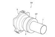
- FIG. 3 is a perspective view of a shield connector according to the second embodiment of the present invention.
- FIG. 4 is a cross-sectional view of a shield connector according to the second embodiment of the present invention.
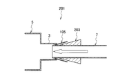
- FIG. 5 is a schematic view before the pressing member of the shield connector according to the third embodiment of the present invention is assembled.
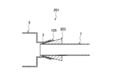
- FIG. 6 is a schematic view when the pressing member of the shield connector according to the third embodiment of the present invention is assembled.
- FIG. 7 is a cross-sectional view of a shield connector according to a fourth embodiment of the present invention.
- a waterproof connector according to an embodiment of the present invention will be described with reference to FIGS.
- FIG. 1st Embodiment is described using FIG. 1, FIG.
- the shield connector 1 includes a shield shell 5 having a cylindrical portion 3 and a cylindrical shield member 7 disposed in the cylindrical portion 3.
- a shield member 7 is inserted into the cylindrical portion 3 on the inner peripheral side, and a terminal portion of the shield member 7 is sandwiched and fixed between the cylindrical portion 3 and the pressing member 9 inserted into the cylindrical portion 3. Yes.
- the pressing member 9 presses the shield member 7 toward the cylindrical portion 3 and fixes the shield member 7 in close contact with the cylindrical portion 3.
- the pressing member 9 includes a crimping ring that crimps the shield member 7 toward the inner peripheral surface of the cylindrical portion 3.
- the shield connector 1 is assembled to the wire lead-out portion side of the housing that accommodates the terminal connected to the terminal portion of the wire.
- the shield connector 1 By covering the outer periphery of the electric wire led out from the housing with the shield connector 1, intrusion and leakage of noise and the like can be prevented.
- the shield connector 1 will be described.
- the shield connector 1 includes a shield shell 5, a shield member 7, and a pressing member 9.
- the shield shell 5 is made of a conductive material, and is assembled to the electric wire outlet portion side of the housing.
- the shield shell 5 is provided with a cylindrical portion 3 into which an electric wire is inserted.
- a shield member 7 is disposed on the inner peripheral side of the cylindrical portion 3.
- the shield member 7 is made of a conductive metal foil formed in a sheet shape, and is formed in a cylindrical shape. The shield member 7 is inserted into the inner periphery of the cylindrical portion 3 of the shield shell 5 and covers the outer periphery of the electric wire led out from the housing.
- the shield member 7 is electrically connected to the shield shell 5 to form a shield circuit that prevents intrusion and leakage of noise and the like with respect to the electric wire.
- Such a shield member 7 is fixed to the cylindrical portion 3 of the shield shell 5 by the pressing member 9.
- the pressing member 9 is composed of a ring-shaped caulking ring that can be expanded in diameter, and is inserted into the inner periphery of the terminal portion of the shield member 7.
- the pressing member 9 is formed on the inner peripheral surface of the cylindrical portion 3 with a jig (not shown) or the like as indicated by an arrow in FIG. 2 in a state where the shield member 7 is inserted into the cylindrical portion 3 of the shield shell 5.
- the shield member 7 is pressed toward the cylindrical portion 3 side so as to increase in diameter, and the outer peripheral surface of the shield member 7 is brought into close contact with the inner peripheral surface of the cylindrical portion 3 and fixed.
- the caulking of the pressing member 9 causes the shield shell 5 and the shield member 7 to conduct to form a shield circuit. Since this shield circuit is formed on the inner peripheral side of the cylindrical portion 3, it is possible to improve the shielding performance against noise as compared with the case where it is formed on the outer peripheral side of the cylindrical portion 3.
- the shield shell 5 and the shield member 7 are not indirect contact such as bolting at other places but directly by the pressing member 9, the contact between the shield shell 5 and the shield member 7. Reliability can be improved.
- the contact portion between the shield shell 5 and the shield member 7 by the pressing member 9 is located on the inner peripheral side of the cylindrical portion 3 and is in close contact with the pressing member 9, it reduces the chance of contact with water or the like, Formation of a gap between the shield shell 5 and the shield member 7 is prevented, and waterproofness and corrosion resistance can be improved.
- the shield member 7 is nipped and fixed to the cylindrical portion 3 by a pressing member 9 inserted into the cylindrical portion 3 of the shield shell 5. Specifically, the cylindrical portion of the shield shell 5 is pressed by the pressing member 9. 3, the contact reliability between the shield shell 5 and the shield member 7 can be directly managed.
- the pressing member 9 is disposed at the terminal portion of the shield member 7, whereby the waterproof treatment between the shield shell 5 and the shield member 7 can be easily performed, and the shield shell The contact reliability between 5 and the shield member 7 can be ensured.
- the pressing member 9 consists of a caulking ring that caulks the shield member 7 toward the inner peripheral surface of the cylindrical portion 3, it can be waterproofed with a simple structure and ensure contact reliability. Can do.
- the pressing member 103 is disposed in a folded portion 105 that is folded back with the end portion of the shield member 7 facing the outer peripheral side.
- a fixing member 107 fixed to the inner periphery of the cylindrical portion 3 is disposed on the outer periphery of the shield member 7, and the pressing member 103 is pressed by the fixing member 107 to press the shield member 7 toward the cylindrical portion 3.
- the pressing member 103 is made of rubber packing as an elastic member that presses the shield member 7 toward the inner peripheral surface of the cylindrical portion 3.
- the cylindrical portion 3 of the shield shell 5 is formed such that the opening side has a larger diameter than the base side, and a step portion 109 is formed on the base side.
- the side surface of the step portion 109 is in contact with the end surface of the folded portion 105 provided at the terminal portion of the shield member 7.
- the folded portion 105 of the shield member 7 is formed by folding the end portion of the shield member 7 to the outer peripheral side by a predetermined length.
- a pressing member 103 is disposed in the folded portion 105.
- the pressing member 103 is formed of a rubber packing as an elastic member that is formed in an annular shape and is elastically deformable, and is disposed in the folded portion 105 so as to be covered with the folded portion 105.
- the pressing member 103 is pressed on the side surface on the opening side by the fixing member 107 fixed to the cylindrical portion 3 in a state where the shield member 7 is inserted into the cylindrical portion 3 of the shield shell 5, and the folded portion of the shield member 7.
- 105 is pressed to the cylindrical portion 3 side, and the outer peripheral surface of the folded portion 105 is brought into close contact with the inner peripheral surface of the cylindrical portion 3 and fixed.
- the fixing member 107 is formed in an annular shape, and is fastened and fixed to the cylindrical portion 3 via a screw portion 111 formed between the outer peripheral surface and the inner peripheral surface of the cylindrical portion 3.
- the fixing member 107 is fastened to the screw portion 111 to press the pressing member 103 between the side wall surface of the stepped portion 109 and elastically deforms the pressing member 103 so that the shield shell 5 and the shield member 7 are connected. Fix in close contact.
- the shield shell 5 and the shield member 7 are electrically connected to form a shield circuit.
- the rubber packing as the pressing member 103 is disposed between the shield shell 5 and the fixing member 107, the space between the shield shell 5 and the fixing member 107 can be reliably waterproofed.
- the pressing member 103 is disposed in the folded portion 105 of the shield member 7, the strength can be improved with respect to a load in a direction of coming out of the cylindrical portion 3 that is applied to the shield member 7.
- the pressing member 103 is disposed in the folded portion 105 that is folded back with the terminal portion of the shield member 7 facing the outer peripheral side, so that the shield member 7 from the cylindrical portion 3 of the shield shell 5 is disposed. Omission can be prevented.
- the pressing member 103 is pressed by the fixing member 107 fixed to the cylindrical portion 3 and presses the shield member 7 to the cylindrical portion 3 side, the pressing force of the pressing member 103 can be increased by the fixing member 107, Waterproofness and contact reliability can be further ensured. In addition, the positional deviation of the pressing member 103 can be prevented by the fixing member 107.
- the pressing member 103 is made of rubber packing as an elastic member that presses the shield member 7 toward the inner peripheral surface of the cylindrical portion 3, it is possible to reliably waterproof between the shield shell 5 and the fixing member 107. it can.
- the pressing member 203 is disposed in a folded portion 105 that is folded with the terminal portion of the shield member 7 turned toward the outer peripheral side.
- the pressing member 203 is formed of a wedge-shaped bush that is press-fitted into the cylindrical portion 3 and presses the shield member 7 toward the inner peripheral surface of the cylindrical portion 3.
- the pressing member 203 is a bush formed in an annular and tapered wedge shape, and is disposed on the folded portion 105 so as to be covered with the folded portion 105. Press fit.
- the pressing member 203 is inserted toward the folded portion 105 as shown by the arrow in FIG. 5 with the folded portion 105 side of the shield member 7 inserted into the cylindrical portion 3 of the shield shell 5 for a predetermined length.
- the folded portion 105 of the shield member 7 is pressed to the cylindrical portion 3 side, and the outer peripheral surface of the folded portion 105 is brought into close contact with the inner peripheral surface of the cylindrical portion 3 and fixed.
- the shield shell 5 and the shield member 7 are brought into conduction to form a shield circuit.
- the bush as the pressing member 203 is disposed between the shield shell 5 and the shield member 7, the space between the shield shell 5 and the shield member 7 can be reliably waterproofed.
- the strength can be improved with respect to a load in a direction of coming out of the cylindrical portion 3 that is applied to the shield member 7.
- the pressing member 203 is press-fitted into the cylindrical portion 3 of the shield shell 5, there is no need to use a member such as the fixing member 107 (see FIG. 4), the number of parts can be reduced, and the assembling property can be improved. can do.
- the pressing member 203 is disposed in the folded portion 105 that is folded back with the end portion of the shield member 7 facing the outer peripheral side, so that the shield member 7 from the cylindrical portion 3 of the shield shell 5 is disposed. Omission can be prevented.
- the pressing member 203 is formed of a wedge-shaped bush that is press-fitted into the cylindrical portion 3 and presses the shield member 7 toward the inner peripheral surface of the cylindrical portion 3. The number of points can be reduced and the assemblability can be improved.
- the pressing member 303 is inserted into the cylindrical portion 3 of the shield shell 5, and the terminal portion of the shielding member 7 is disposed between the cylindrical portion 3 and the pressing member 303 and is cylindrical. By crimping the portion 3 toward the pressing member 303 side, the shield member 7 is closely attached between the cylindrical portion 3 and the pressing member 303 and fixed.
- the pressing member 303 is formed of a member that is formed in an annular shape and has a reaction force against an external force applied from the outer peripheral side toward the inner peripheral side, and is inserted into the inner periphery of the terminal portion of the shield member 7. Is disposed between the cylindrical portion 3 and the pressing member 303.
- the pressing member 303 has the shielding member 7 inserted into the cylindrical portion 3 of the shielding shell 5 and, as shown by the arrow in FIG.
- the shield member 7 is pressed toward the cylindrical portion 3 by a reaction force caused by crimping toward the cylindrical portion 3, and the outer peripheral surface of the shield member 7 is brought into close contact with the inner peripheral surface of the cylindrical portion 3 and fixed.
- the shield shell 5 and the shield member 7 are electrically connected to form a shield circuit. Since this shield circuit is formed on the inner peripheral side of the cylindrical portion 3, it is possible to improve the shielding performance against noise as compared with the case where it is formed on the outer peripheral side of the cylindrical portion 3.
- the shield shell 5 and the shield member 7 are not indirect contact such as bolt fastening in other places, but directly contacted by the reaction force of the pressing member 303 by caulking of the cylindrical portion 3, The contact reliability between the shield shell 5 and the shield member 7 can be improved.
- the contact portion between the shield shell 5 and the shield member 7 due to the reaction force of the pressing member 303 is located on the inner peripheral side of the cylindrical portion 3 and is in close contact with the pressing member 303, so there is an opportunity to contact with water or the like. This can reduce the formation of a gap between the shield shell 5 and the shield member 7 and improve waterproofness and corrosion resistance.
- the terminal portion of the shield member 7 is disposed between the cylindrical portion 3 and the pressing member 303, and the cylindrical member 3 is caulked toward the pressing member 303 side, whereby the shield member 7 is connected to the cylindrical portion. 3 and the pressing member 303 are closely attached and fixed so that no gap is formed at the contact portion between the shield shell 5 and the shield member 7.
- the shield member 7 is fixed in close contact with the cylindrical portion 3 of the shield shell 5 by the reaction force of the pressing member 303 by caulking the cylindrical portion 3, the contact reliability between the shield shell 5 and the shield member 7 is secured. Can be directly managed.
- the waterproofing treatment between the shield shell 5 and the shield member 7 can be easily performed by disposing the pressing member 303 at the terminal portion of the shield member 7, and the shield shell The contact reliability between 5 and the shield member 7 can be ensured.
- the shield member is a conductive metal foil formed in a sheet shape, but is not limited to this, and is a braided conductor formed in a stitch shape. Also good.
- the caulking ring as the pressing member is inserted on the inner peripheral side of the shield member, but not limited to this, the caulking ring is arranged at the folded portion of the shield member and is caulked toward the inner peripheral surface of the cylindrical portion. Also good.
- the fixing of the cylindrical portion of the shield shell and the fixing member is screw connection, but is not limited to this, for example, uneven engagement and adhesion, spline connection and adhesion, press fitting of the fixing member to the cylindrical portion, etc. Any configuration may be used as long as the fixing member can be fixed to the cylindrical portion and the pressing member can be pressed by the fixing member.
- the pressing member is not limited to a caulking ring, a rubber packing, a bush, or the like, and any member can be used as long as it can seal between the shield shell and the shield member or between the shield shell and the fixing member. May be.
Landscapes
- Connector Housings Or Holding Contact Members (AREA)
- Details Of Connecting Devices For Male And Female Coupling (AREA)
Abstract
Description
Claims (3)
- 円筒部を有するシールドシェルと、
前記円筒部の内周側に配置される円筒状のシールド部材と、
前記シールド部材を挟んで前記円筒部の内周側に配置される押圧部材であって、前記シールド部材の端末部を前記円筒部側に押圧して前記シールド部材と前記円筒部とを密着させて固定する押圧部材と、
を備えたシールドコネクタ。 - 前記シールド部材は、前記シールド部材の端末部を前記シールド部材の外周側に向けて折り返した折返部を有し、
前記押圧部材は、前記折返部に配置された
請求項1記載のシールドコネクタ。 - 前記シールド部材の外周に配置され、前記円筒部の内周に固定され、前記押圧部材を押圧する固定部材をさらに備え、
前記押圧部材は、前記固定部材による押圧を受けて前記シールド部材を前記円筒部側に押圧する
請求項2記載のシールドコネクタ。
Priority Applications (3)
| Application Number | Priority Date | Filing Date | Title |
|---|---|---|---|
| US14/440,884 US20150303611A1 (en) | 2012-11-15 | 2013-10-22 | Shielded connector |
| DE112013005463.9T DE112013005463T5 (de) | 2012-11-15 | 2013-10-22 | Abgeschirmter Verbinder |
| CN201380058938.2A CN104781997A (zh) | 2012-11-15 | 2013-10-22 | 屏蔽连接器 |
Applications Claiming Priority (2)
| Application Number | Priority Date | Filing Date | Title |
|---|---|---|---|
| JP2012250864A JP2014099339A (ja) | 2012-11-15 | 2012-11-15 | シールドコネクタ |
| JP2012-250864 | 2012-11-15 |
Publications (1)
| Publication Number | Publication Date |
|---|---|
| WO2014077091A1 true WO2014077091A1 (ja) | 2014-05-22 |
Family
ID=50731010
Family Applications (1)
| Application Number | Title | Priority Date | Filing Date |
|---|---|---|---|
| PCT/JP2013/078548 Ceased WO2014077091A1 (ja) | 2012-11-15 | 2013-10-22 | シールドコネクタ |
Country Status (5)
| Country | Link |
|---|---|
| US (1) | US20150303611A1 (ja) |
| JP (1) | JP2014099339A (ja) |
| CN (1) | CN104781997A (ja) |
| DE (1) | DE112013005463T5 (ja) |
| WO (1) | WO2014077091A1 (ja) |
Families Citing this family (5)
| Publication number | Priority date | Publication date | Assignee | Title |
|---|---|---|---|---|
| JP6451568B2 (ja) | 2015-09-14 | 2019-01-16 | 株式会社オートネットワーク技術研究所 | シールドコネクタ |
| US10680355B2 (en) | 2016-01-27 | 2020-06-09 | Aptiv Technologies Limited | Terminal assembly for shielded cable |
| JP6230013B1 (ja) * | 2017-04-07 | 2017-11-15 | Smk株式会社 | 電気コネクタ |
| EP3425741B1 (en) * | 2017-07-05 | 2022-08-24 | Aptiv Technologies Limited | Terminal assembly for shielded cable |
| DE102018121582A1 (de) | 2018-09-04 | 2020-03-05 | Rosenberger Hochfrequenztechnik Gmbh & Co. Kg | Elektrische Verteilervorrichtung, Montageverfahren und Signalübertragungssystem |
Citations (2)
| Publication number | Priority date | Publication date | Assignee | Title |
|---|---|---|---|---|
| JP2003179381A (ja) * | 2001-12-11 | 2003-06-27 | Auto Network Gijutsu Kenkyusho:Kk | 機器用シールドコネクタ装置 |
| JP2012138199A (ja) * | 2010-12-24 | 2012-07-19 | Yazaki Corp | シールドコネクタ |
Family Cites Families (12)
| Publication number | Priority date | Publication date | Assignee | Title |
|---|---|---|---|---|
| JPH0386577U (ja) * | 1989-12-21 | 1991-09-02 | ||
| JP2537434B2 (ja) * | 1991-03-08 | 1996-09-25 | 横河航空電機株式会社 | グランディングコネクタ構造 |
| JP2000164302A (ja) * | 1998-11-25 | 2000-06-16 | Furukawa Electric Co Ltd:The | シールド電線用コネクタ |
| JP2002008744A (ja) * | 2000-06-20 | 2002-01-11 | Auto Network Gijutsu Kenkyusho:Kk | シールド電線の端末接続構造 |
| JP4316482B2 (ja) * | 2004-12-03 | 2009-08-19 | 矢崎総業株式会社 | シールド電線のアース処理方法及びアース処理構造 |
| JP4744419B2 (ja) * | 2006-11-10 | 2011-08-10 | 矢崎総業株式会社 | シールド端末処理方法、およびシールド端末処理構造 |
| KR100993098B1 (ko) * | 2008-12-18 | 2010-11-08 | 엘에스전선 주식회사 | 고정용 압착밴드, 이를 이용하여 차폐 커넥터와 일괄형 편조차폐선을 결합하는 방법 및, 차폐 커넥터 구조체 |
| CN201774089U (zh) * | 2010-05-08 | 2011-03-23 | 吕永锋 | 一种具有屏蔽密封结构的连接器附件 |
| CN101888043A (zh) * | 2010-06-21 | 2010-11-17 | 贵州航天电器股份有限公司 | 一种屏蔽端接附件 |
| JP2012104417A (ja) * | 2010-11-11 | 2012-05-31 | Toyota Motor Corp | コネクタ |
| JP5833300B2 (ja) * | 2010-11-11 | 2015-12-16 | 矢崎総業株式会社 | コネクタ |
| JP2013162724A (ja) * | 2012-02-08 | 2013-08-19 | Sumitomo Wiring Syst Ltd | シールドシェルへのシールド用筒状編組部材の固定方法 |
-
2012
- 2012-11-15 JP JP2012250864A patent/JP2014099339A/ja not_active Abandoned
-
2013
- 2013-10-22 DE DE112013005463.9T patent/DE112013005463T5/de not_active Ceased
- 2013-10-22 CN CN201380058938.2A patent/CN104781997A/zh active Pending
- 2013-10-22 US US14/440,884 patent/US20150303611A1/en not_active Abandoned
- 2013-10-22 WO PCT/JP2013/078548 patent/WO2014077091A1/ja not_active Ceased
Patent Citations (2)
| Publication number | Priority date | Publication date | Assignee | Title |
|---|---|---|---|---|
| JP2003179381A (ja) * | 2001-12-11 | 2003-06-27 | Auto Network Gijutsu Kenkyusho:Kk | 機器用シールドコネクタ装置 |
| JP2012138199A (ja) * | 2010-12-24 | 2012-07-19 | Yazaki Corp | シールドコネクタ |
Also Published As
| Publication number | Publication date |
|---|---|
| JP2014099339A (ja) | 2014-05-29 |
| DE112013005463T5 (de) | 2015-08-20 |
| CN104781997A (zh) | 2015-07-15 |
| US20150303611A1 (en) | 2015-10-22 |
Similar Documents
| Publication | Publication Date | Title |
|---|---|---|
| US9325120B2 (en) | Wire harness and connection structure of shield shell and braided shield | |
| JP5768618B2 (ja) | ワイヤハーネスの端末防水構造 | |
| JP6234034B2 (ja) | シールドコネクタ構造 | |
| JP6130722B2 (ja) | 端子接続構造 | |
| JP6086381B2 (ja) | コネクタ構造 | |
| CN102893459B (zh) | 屏蔽连接器 | |
| US8986045B2 (en) | Connecting structure of shield braided part | |
| JP6053920B2 (ja) | コネクタの防水構造 | |
| JP5914679B2 (ja) | シールドコネクタ | |
| JP2010061891A (ja) | コネクタ | |
| JP2014099339A (ja) | シールドコネクタ | |
| JP5367881B1 (ja) | コネクタ、およびコネクタ接続構造 | |
| WO2016147376A1 (ja) | ワイヤハーネス | |
| JP5367882B1 (ja) | コネクタおよびコネクタ接続構造 | |
| CN110190451A (zh) | 接线器及其屏蔽套组件 | |
| WO2019004207A1 (ja) | シールド付き電線用コネクタ | |
| WO2017047468A1 (ja) | シールドコネクタ | |
| JP2016213053A (ja) | パッキン、コネクタ及びワイヤハーネス | |
| JP2002270281A (ja) | 防水型シールドコネクタ | |
| JP2016006733A (ja) | 組合せ端子金具 | |
| JP2010176960A (ja) | 電気コネクタ | |
| JP2006294514A (ja) | シールド金具及び該シールド金具を備えたシールド構造 | |
| JP5390362B2 (ja) | コネクタユニット | |
| WO2015063917A1 (ja) | シールドシェルの固定構造 | |
| JP2000092651A (ja) | 導電性チューブの接続方法及び接続構造 |
Legal Events
| Date | Code | Title | Description |
|---|---|---|---|
| 121 | Ep: the epo has been informed by wipo that ep was designated in this application |
Ref document number: 13855789 Country of ref document: EP Kind code of ref document: A1 |
|
| WWE | Wipo information: entry into national phase |
Ref document number: 14440884 Country of ref document: US |
|
| WWE | Wipo information: entry into national phase |
Ref document number: 112013005463 Country of ref document: DE Ref document number: 1120130054639 Country of ref document: DE |
|
| 122 | Ep: pct application non-entry in european phase |
Ref document number: 13855789 Country of ref document: EP Kind code of ref document: A1 |