WO2014073652A1 - 電極材料及び電極材料の製造方法 - Google Patents
電極材料及び電極材料の製造方法 Download PDFInfo
- Publication number
- WO2014073652A1 WO2014073652A1 PCT/JP2013/080293 JP2013080293W WO2014073652A1 WO 2014073652 A1 WO2014073652 A1 WO 2014073652A1 JP 2013080293 W JP2013080293 W JP 2013080293W WO 2014073652 A1 WO2014073652 A1 WO 2014073652A1
- Authority
- WO
- WIPO (PCT)
- Prior art keywords
- electrode material
- electrode
- layer
- less
- primary particles
- Prior art date
Links
Images


Classifications
-
- H—ELECTRICITY
- H01—ELECTRIC ELEMENTS
- H01M—PROCESSES OR MEANS, e.g. BATTERIES, FOR THE DIRECT CONVERSION OF CHEMICAL ENERGY INTO ELECTRICAL ENERGY
- H01M4/00—Electrodes
- H01M4/02—Electrodes composed of, or comprising, active material
- H01M4/36—Selection of substances as active materials, active masses, active liquids
- H01M4/362—Composites
- H01M4/366—Composites as layered products
-
- H—ELECTRICITY
- H01—ELECTRIC ELEMENTS
- H01M—PROCESSES OR MEANS, e.g. BATTERIES, FOR THE DIRECT CONVERSION OF CHEMICAL ENERGY INTO ELECTRICAL ENERGY
- H01M4/00—Electrodes
- H01M4/02—Electrodes composed of, or comprising, active material
- H01M4/36—Selection of substances as active materials, active masses, active liquids
- H01M4/58—Selection of substances as active materials, active masses, active liquids of inorganic compounds other than oxides or hydroxides, e.g. sulfides, selenides, tellurides, halogenides or LiCoFy; of polyanionic structures, e.g. phosphates, silicates or borates
- H01M4/5825—Oxygenated metallic salts or polyanionic structures, e.g. borates, phosphates, silicates, olivines
-
- H—ELECTRICITY
- H01—ELECTRIC ELEMENTS
- H01M—PROCESSES OR MEANS, e.g. BATTERIES, FOR THE DIRECT CONVERSION OF CHEMICAL ENERGY INTO ELECTRICAL ENERGY
- H01M10/00—Secondary cells; Manufacture thereof
- H01M10/05—Accumulators with non-aqueous electrolyte
- H01M10/052—Li-accumulators
- H01M10/0525—Rocking-chair batteries, i.e. batteries with lithium insertion or intercalation in both electrodes; Lithium-ion batteries
-
- H—ELECTRICITY
- H01—ELECTRIC ELEMENTS
- H01M—PROCESSES OR MEANS, e.g. BATTERIES, FOR THE DIRECT CONVERSION OF CHEMICAL ENERGY INTO ELECTRICAL ENERGY
- H01M4/00—Electrodes
- H01M4/02—Electrodes composed of, or comprising, active material
- H01M4/62—Selection of inactive substances as ingredients for active masses, e.g. binders, fillers
- H01M4/624—Electric conductive fillers
- H01M4/625—Carbon or graphite
-
- Y—GENERAL TAGGING OF NEW TECHNOLOGICAL DEVELOPMENTS; GENERAL TAGGING OF CROSS-SECTIONAL TECHNOLOGIES SPANNING OVER SEVERAL SECTIONS OF THE IPC; TECHNICAL SUBJECTS COVERED BY FORMER USPC CROSS-REFERENCE ART COLLECTIONS [XRACs] AND DIGESTS
- Y02—TECHNOLOGIES OR APPLICATIONS FOR MITIGATION OR ADAPTATION AGAINST CLIMATE CHANGE
- Y02E—REDUCTION OF GREENHOUSE GAS [GHG] EMISSIONS, RELATED TO ENERGY GENERATION, TRANSMISSION OR DISTRIBUTION
- Y02E60/00—Enabling technologies; Technologies with a potential or indirect contribution to GHG emissions mitigation
- Y02E60/10—Energy storage using batteries
Definitions
- the present invention relates to an electrode material that can be used for a lithium ion secondary battery or the like and a method for producing the electrode material.
- lithium metal phosphates such as LiFePO 4 having an olivine crystal structure (space group Pnma) have been used as electrodes for lithium ion secondary batteries and the like.
- Lithium metal phosphate is excellent in terms of cost, safety, durability, and the like, but is poor in electronic conductivity and Li ion conductivity.
- the surface of the electrode active material may need to be subjected to carbon coating treatment in order to supplement electron conductivity.
- Li ion conductivity lithium metal phosphate can only have a one-dimensional ion conduction direction, and the degree of freedom in the diffusion direction is low, and the Li diffusivity itself is also low. For this reason, there have been attempts to supplement the conductivity (diffusibility) of Li ions by coating the surface of the electrode active material with a Li ion conductive layer.
- Patent Document 1 discloses an electrode active material coated with a coating layer made of LiFePO 4 and a coating layer containing carbon in the electrode active material represented by the general formula LiMnPO 4 .
- Patent Document 2 discloses a core containing Li, M, P, and O (where M is at least one of Fe, Mn, Co, and Ni), at least one of N and C, and Li, M. Particles coated with an oxide coating comprising, P and O are disclosed. In this case, a mode in which Li ion conductivity (diffusibility) is supplemented by the oxide coating and high input / output characteristics are exhibited is shown.
- Patent Document 3 discloses an electrode material in which a surface of the electrode active material is coated with a composite coating layer made of conductive carbon and a Li ion conductive material.
- the surface of the electrode active material is coated with a composite coating layer composed of conductive carbon and a Li ion conductive material, whereby the electron conductivity and the Li ion conductivity are covered. Improves both sex.
- the primary particle size of the electrode active material is reduced because the electron conductivity and Li ion conductivity of the electrode active material are low. Accordingly, it is necessary to increase the contact area between the carbon coat and the Li ion conductive material and the electrode active material to supplement the electron conductivity, and limit the diffusion distance of Li ions in the electrode active material.
- the secondary particle size is also reduced, and the viscosity of the coating dispersion for using the electrode active material as an electrode material is increased.
- Patent Document 1 Patent Document 2 and Patent Document 3 do not describe the deterioration of coating property and the coating layer, and do not describe means for solving them.
- an object of the present invention is to improve compatibility between electronic conductivity and lithium ion conductivity in an electrode using lithium metal phosphate, to obtain excellent electrode characteristics, and to deteriorate coating properties and coating properties. It is to suppress the deterioration of the layer.
- the area equivalent diameter determined by the following formula (1) from the specific surface area by the nitrogen adsorption Brunauer-Emmett Taylor (BET) multipoint method is 45 nm or more.
- Formula (1) (Area equivalent diameter) 6 / ⁇ (true density of electrode active material) ⁇ (specific surface area) ⁇
- binding means to include both chemical bonds and physical bonds.
- the general formula LiMPO 4 means that Li: M: P: O contains each component at a ratio of approximately 1: 1: 1: 4. That is, it does not require that each component is contained at a ratio of 1: 1: 1: 4 strictly or that no impurities are contained.
- the Li ion conductive material is provided with a layer including a Li ion conductive material including Li, at least one of Fe and Mn, and P and O
- the Li ions can form the layer in two or three dimensions. It becomes movable originally, and Li ion conductivity can be increased.
- the layer containing the conductive carbon C is provided, the electron conductivity can be increased. That is, compatibility between electronic conductivity and lithium ion conductivity can be improved.
- the Li ions are It becomes possible to move two-dimensionally or three-dimensionally from one primary particle to another primary particle through the layer, and Li ion conductivity can be increased.
- electrons can move from one primary particle to another primary particle through a layer containing conductive carbon C, electron conductivity can be increased. In other words, compatibility between electronic conductivity and lithium ion conductivity can be further improved.
- the electrode material according to the second aspect of the present invention is the electrode material according to the first aspect, wherein the flat plate surface at the time of compression molding into a flat plate pellet is irradiated with X-rays of single-crystal spectral Al-K ⁇ ,
- each of C1s, Li1s, Fe2p3 / 2, Mn2p3 / 2, P2p and O1s surface composition calculated from narrow scan results of electron orbit, characterized by being represented by the formula C c Li a Fe x Mn 1 -x P y O z.
- ⁇ is a number satisfying the following formula (3) when it is assumed that the average valences N Fe and N Mn are both 2)
- Formula (2) z [ ⁇ a + xN Fe + (1-x) N Mn + 5y ⁇ / 2] ⁇
- the Li ion conductive substance contains an amount of Li ions effective to express high Li ion conductivity and (poly) phosphate ions.
- the Li ion conductive material contains at least one of Fe and Mn, which are transition metal elements, in an amount effective for exhibiting electronic conductivity.
- the amount of ⁇ corresponding to oxygen vacancies in the Li ion conductive material may be zero, but when the amount is a positive amount within the range of the above formula (3) indicating the range of the oxygen vacancy rate, the Li Since the ion conductive material may have n-type semiconductivity, it may have higher electronic conductivity. When ⁇ is larger than the range of the above formula (3), the structural stability as a substance may be impaired.
- conductive carbon C is also included in a quantitative ratio effective for imparting electron conductivity.
- the electrode material provided with a layer containing such a Li ion conductive substance and conductive carbon C exhibits good charge / discharge characteristics.
- the take-off angle is 53 ⁇ 10 degrees” is not limited to “53 ⁇ 10 degrees” in a strict sense, but also includes its peripheral values.
- Electrode material according to the third aspect of the present invention in the second embodiment, in the general formula C c Li a Fe x Mn 1 -x P y O z, a is 2.0 to 3.0 And y is 1.5 or more and 1.6 or less.
- the Li ion conductive material has particularly excellent Li ion conductivity and also has effective electronic conductivity.
- the electrode material provided with a layer containing a substance and conductive carbon C exhibits particularly good charge / discharge characteristics.
- a is 2.5 or more and 3.0 or less.
- y is more than 1.6 and not more than 2.0.
- the electrode material according to a fifth aspect of the present invention is the electrode material according to any one of the first to fourth aspects, wherein the primary particles have an average particle diameter of 20 nm or more and less than the area equivalent diameter. It is characterized by.
- This “average particle diameter” is the particle diameter d (here, the average value of the major and minor diameters of the primary particles) obtained by observation with a high resolution electron microscope (transmission type and scanning type) and the observed primary particles. It is a body area average diameter calculated from the number n of n by the formula ( ⁇ nd 3 / ⁇ nd 2 ).
- the field of view is appropriately selected so that sufficient n can be secured.
- the average particle diameter of the primary particles is smaller than the area equivalent diameter calculated from the specific surface area obtained by the nitrogen adsorption BET multipoint method. This indicates that there is a portion where the nitrogen gas used for the measurement of the BET specific surface area cannot be contacted / adsorbed on the entire surface of all the primary particles constituting the electrode material of this embodiment.
- the electrode coating dispersion liquid cannot enter and contact the binding site as in the case of nitrogen used for the BET specific surface area measurement.
- the binding site has both Li ion conductivity and electronic conductivity as described above, when the electrode material for the main body is used for a battery, the active material primary particles at the binding site are used as the electrode material.
- the electrode material of this aspect the average particle diameter of the primary particle of an electrode active material is 20 nm or more. If the average particle size of the primary particles is smaller than this, the electrode active material is altered and the charge / discharge capacity is reduced.
- the electrode material according to a sixth aspect of the present invention is the electrode material according to any one of the first to fifth aspects, wherein the maximum secondary particle size is any one of the first to fifth aspects.
- the electrode material has a direct current conductivity of 10 ⁇ 6 S / cm or more at 25 ° C. after being pulverized so as to be 20 ⁇ m or less and compressed at 60 MPa.
- the electrode material of this embodiment has high electron conductivity, it exhibits good charge / discharge characteristics, and when the electrode material is used as a battery electrode, it is coated with an electrode material that is smooth, has a high packing density, and is difficult to peel off.
- a construction layer can be formed. Note that “the maximum secondary particle size is 20 ⁇ m or less” is not limited to “20 ⁇ m or less” in a strict sense, but also includes its peripheral values. Further, the “DC conductivity of the electrode material at 25 ° C. in a state compressed at 60 MPa” is not limited to “60 MPa” and “25 ° C.” in a strict sense, but “peripheral values of the electrode material” It also includes “DC conductivity”.
- the redox potential on the basis of the electrode potential of metal Li / Li + is as high as about 4.1V. It becomes an electrode material having a potential. Therefore, it can be used as a high energy density electrode material that can be easily replaced with conventional electrode materials such as layered crystal structure LiCoO 2 having a similar redox potential and spinel type crystal structure LiMn 2 O 4. become.
- the electrode material according to an eighth aspect of the present invention is characterized in that, in the seventh aspect, the area equivalent diameter is 70 nm or less.
- the Li ion conductivity in the electrode active material becomes extremely poor, and the specific surface area is too small.
- the contact interface between the electrode material and the Li ion conducting medium such as an electrolyte sealed in the battery is insufficient.
- the electrode material made of an electrode active material having a layer containing the above-described Li ion conductive material it is difficult to obtain good battery characteristics.
- the area equivalent diameter is sufficiently small, and therefore the specific surface area is sufficiently large, so that the contact interface can be sufficiently ensured, so that good battery characteristics can be obtained.
- the electrode material according to the ninth aspect of the present invention is characterized in that, in the eighth aspect, the area equivalent diameter is 60 nm or less.
- the area equivalent diameter is further reduced, and therefore the specific surface area is further increased. Therefore, the contact interface can be further sufficiently secured, so that very good battery characteristics can be obtained.
- the electrode material according to a tenth aspect of the present invention is the electrode material according to any one of the first to ninth aspects, wherein the layer containing the Li ion conductive substance and the conductive carbon C is an amorphous layer.
- the amorphous layer means a layer having an amorphous structure, and a part thereof may have a crystal structure.
- the layer is an amorphous layer, Li ions can move three-dimensionally through the layer, and Li ion conductivity is higher. In other words, compatibility between electronic conductivity and lithium ion conductivity can be further improved.
- the electrode material according to an eleventh aspect of the present invention is characterized in that, in any one of the first to tenth aspects, the area equivalent diameter is 50 nm or more.
- the specific surface area is limited to these values or less, the viscosity of the coating dispersion is kept low even when the amount ratio of the electrode material is further increased when preparing the coating dispersion. be able to. Thereby, deterioration of coating property and deterioration of a coating layer can be suppressed further.
- a mixing step 1 for dispersing and mixing a fine powder electrode active material substrate, a raw material to be a Li ion source, and a raw material to be an ion source of at least one of Fe ions and Mn ions;
- a mixing step 2 for dispersing and mixing the mixture obtained in the mixing step 1 and a raw material to be a phosphate ion source or a polyvalent phosphate ion source, and the mixture and conductive carbon C source obtained in the mixing step 2
- each raw material added to the electrode active material substrate is dispersed or mixed in a dry manner or dispersed or dissolved in an appropriate solvent such as water or alcohol. Can be made. If necessary, a step of distilling off the solvent may be added after these steps. Moreover, the mixing process 1 and the mixing process 2 may be simultaneously performed as a single process.
- the area equivalent diameter determined by the following formula (1) from the specific surface area by the nitrogen adsorption BET multipoint method is obtained.
- An electrode material having a relatively small specific surface area such as 45 nm or more can be produced.
- the viscosity of the coating dispersion can be kept low even if the quantity ratio of the electrode material is increased. it can. Thereby, deterioration of coating property and deterioration of a coating layer can be suppressed.
- Formula (1) (Area equivalent diameter) 6 / ⁇ (true density of electrode active material) ⁇ (specific surface area) ⁇
- a part or most of at least one of Fe and Mn in the raw material serving as an ion source of at least one of the Fe ions and Mn ions added in the mixing step 1 is contained.
- the composition inside the primary particles of the electrode active material changes from the original composition, or Fe and Mn in the Li ion conductive material existing on the surface of the primary particles.
- the content of at least one of the above may change from the additive composition of at least one of Fe and Mn in the raw material serving as an ion source of at least one of the Fe ions and Mn ions added in the mixing step 1 .
- FIG. 4 is a diagram showing the X-ray diffraction result of Example 1.
- FIG. 6 is a diagram showing the X-ray diffraction result of Example 2. It is a figure which shows the constant current discharge rate characteristic of Example 1.
- FIG. It is a figure which shows the constant current discharge rate characteristic of Example 2.
- LiMPO 4 [Fe t Mn 1-t ]
- t is a number of 0 or more and 1 or less
- electrochemical oxidation Alternatively, Li ions are released or occluded along with the reduction. And, in the process of oxidation or reduction, it has a crystal structure in which the cation can move only in the one-dimensional allowable movement direction inside the crystal lattice.
- Examples of such an electrode active material include those having an olivine type crystal structure (orthorhombic system, space group Pnma) represented by LiMPO 4 .
- LiMPO 4 the general formula LiMPO 4 means that Li: M: P: O contains each component at a ratio of approximately 1: 1: 1: 4. That is, it does not require that each component is contained at a ratio of 1: 1: 1: 4 strictly or that no impurities are contained.
- M is at least one of Fe and Mn. Therefore, in the case where a plurality of these are included, the total number of these is included in the present invention as long as each component is contained such that Li: M: P: O is approximately 1: 1: 1: 4, where M is the number. It is.
- an electrode active material in which 80% or more of M is Mn is preferable. In such an electrode active material, redox based on the electrode potential of metal Li / Li + in a usage range of 80% or more of the electrode active material.
- the electrode material has a high potential of about 4.1V. Therefore, it can be used as a high energy density electrode material that can be easily replaced with conventional electrode materials such as layered crystal structure LiCoO 2 having a similar redox potential and spinel type crystal structure LiMn 2 O 4. become.
- the electrode active material in the electrode material of the present invention preferably has an average primary particle diameter of 20 nm or more and less than the area equivalent diameter.
- the average particle size is determined by observation with a high-resolution electron microscope (transmission type and scanning type), etc. (here, the average value of the major and minor diameters of the primary particles is used) and the observed primary particles. It is a body area average diameter calculated from the number n of n by the formula ( ⁇ nd 3 / ⁇ nd 2 ).
- the field of view is appropriately selected so that sufficient n can be secured.
- the average particle diameter of primary particles of the electrode active material is smaller than the area equivalent diameter calculated from the specific surface area obtained by the nitrogen adsorption BET multipoint method. This indicates that there is a site where the nitrogen gas used for the measurement of the BET specific surface area does not contact and adsorb among all the surfaces of all the primary particles constituting the electrode material of this embodiment.
- a plurality of primary particles are aggregated, and the primary particles are bound to each other mainly through a layer containing the Li ion conductive material and conductive carbon to form dense secondary particles. is doing.
- the binding liquid is not infiltrated / contacted with the binding site as in the case of nitrogen used for the BET specific surface area measurement. Since the interaction with the polar polymer binder such as PVDF added to the coating dispersion liquid hardly occurs at the site, an increase in the viscosity of the coating dispersion liquid is suppressed and deterioration of the coating layer can be prevented.
- the binding site has both Li ion conductivity and electronic conductivity as described above, when the electrode material for the main body is used for a battery, the active material primary particles at the binding site are used as the electrode material. Works well.
- the average particle diameter of a primary particle is 20 nm or more. If the average particle size of the primary particles is smaller than this, the electrode active material is altered and the charge / discharge capacity is reduced.
- the electrode active material can be synthesized based on a known wet manufacturing method, solid phase baking manufacturing method, or solid phase baking manufacturing method of a reaction intermediate by wet synthesis (for example, so-called sol-gel manufacturing method).
- a known wet manufacturing method solid phase baking manufacturing method, or solid phase baking manufacturing method of a reaction intermediate by wet synthesis
- sol-gel manufacturing method for example, so-called sol-gel manufacturing method.
- an electrode active material corresponding to LiMPO 4 having an olivine type crystal structure or an electrode material containing the same is disclosed in JP 2002-151082 (wet manufacturing method) and JP 2004-095385 (wet manufacturing method).
- JP-A No. 2007-119304 wet manufacturing method
- JP-A No. 9-134724 solid-phase baking manufacturing method
- JP-A No. 2004-63386 solid-phase baking manufacturing method
- JP-A No. 2003-157845 sol-gel manufacturing method
- a substance containing Li, at least one of Fe and Mn, and P and O is used as a Li ion conductive substance.
- the Li ion conductive material has a property that allows two-dimensional or three-dimensional internal movement of Li ions. More preferably, the layer containing Li ion conductive material has a 10 -8 S / cm or equivalent ionic conductivity based on diffusion transfer of Li ions, more than 10 -8 S / cm electric conductivity. Even more preferably, it has a 10 -6 S / cm or equivalent of the ion conductivity, a 10 -6 S / cm or equivalent electron conductivity.
- This electronic conductivity can be brought about by the Li ion conductive material containing a certain amount or more of a transition metal element (here, at least one of Fe and Mn).
- the Li ion conductive material containing such a transition metal element as a constituent element functions not only as a Li ion conduction path, but also as an electron conduction path with the electrode active material primary particles represented by the general formula LiMPO 4 , As a whole of the electrode material, polarization in charge / discharge can be reduced.
- Examples of such a Li ion conductive material include a material having a basic composition of (poly) phosphate partially substituted with Fe and Mn, and the following compounds in which a plurality of these are combined (in the following, r is a positive number of 1 or less, preferably about 0.3 or less, and the coefficient of Li is a positive number).
- Li 3-2r Fe (II) r PO 4 Li 2-2r Fe (II) r P 2 O 7 , Li 3-3r Fe (III) r PO 4 , Li 2-3r Fe (III) r P 2 O 7 , Li 9-4r Fe (II) 2r (PO 4 ) 3 , Li 9-6r Fe (III) 2r (PO 4 ) 3 etc.
- Li 3-2r Mn (II) r PO 4 Li 2-2r Mn (II) x P 2 O 7 , Li 3-3r Mn (III) r PO 4 , Li 2-3r Mn (III) r P 2 O 7 , Li 9-4r Mn (II) 2r (PO 4 ) 3 , Li 9-6r Mn (III) 2r (PO 4 ) 3 etc.
- the Li ion conductive substance has an amorphous structure at least partially. This is because Li ions can move three-dimensionally in the material and Li ion conductivity is further increased.
- the Li ion conductive material may contain at least one of Fe and Mn and one or more other elements in addition to P and O. When the element is a transition metal element, the electron conductivity may be further increased.
- each element ratio in each example of the Li ion conductive material is not limited to a strict ratio represented by these chemical formulas, and may be at least partially substituted or changed.
- a part of the constituent elements may be lost or excessive stoichiometrically.
- bitumens such as tar and coal pitch, which are subjected to thermal decomposition from a partially molten state to produce conductive carbon, aromatic compounds, chain hydrocarbons, or derivatives thereof , Sugars such as dextrin, or derivatives thereof can be used.
- the layer thickness is preferably 0.6 nm or more and 5 nm or less in observation with a high-resolution transmission electron microscope or the structure evaluation means having the same resolution as described above.
- the surface layer of the primary particles is preferably an amorphous layer. This is because Li ions can move three-dimensionally in the layer, and Li ion conductivity is further increased.
- the amorphous layer means a layer having an amorphous structure, and a part thereof may have a crystal structure. It is possible to confirm whether or not this surface layer is an amorphous layer using a high-resolution transmission electron microscope or the like.
- FIG. 1 shows a schematic diagram of an electrode material according to an embodiment of the present invention.
- An electrode material 1 includes a plurality of primary particles through an outer layer 4 as a composite layer in which primary particles 2 of an electrode active material LiMPO 4 include a Li ion conductive material and conductive carbon C. Are formed as secondary particles formed by agglomeration and binding to each other. Further, an inner layer 3 made of a Li ion conductive material is provided between the primary particles 2 and the outer layer 4. Note that the inner layer 3 and the outer layer 4 contain Li, a Li ion conductive material containing P and O, and at least one of Fe and Mn. Further, in the primary particles 2 of the electrode active material LiMPO 4 , Li ions can move only in one direction in the direction A. However, in the inner layer 3 and the outer layer 4, Li ions can move two-dimensionally or three-dimensionally.
- the layer provided on the surface of the primary particle 2 includes an inner layer 3 made of a Li ion conductive material, a composite layer containing a Li ion conductive material and conductive carbon C.
- the outer layer 4 is clearly divided.
- the present invention also includes a case where the inner layer 3 and the outer layer 4 form an integrated composite layer without having a clear boundary between them.
- a composite layer containing a Li ion conductive material and conductive carbon C is provided on the surface of primary particles of the electrode active material LiMPO 4 .
- an electrode material using LiMPO 4 as an electrode active material has been made to increase the contact area with an electrolytic solution in order to improve its charge / discharge characteristics.
- an electrode active material is used that has a large specific surface area, allows the electrolyte to penetrate well into the gaps between the primary particles in the secondary particles, and easily contacts the primary particles.
- a coating dispersion in which the electrode material and a conductive auxiliary agent are mixed and dispersed together with a commonly used polar polymer binder such as PVDF is used.
- the interaction between the electrode material surface and the polar polymer binder is strong, and the viscosity of the coating dispersion tends to increase. For this reason, when the solid content concentration of the electrode material and the like in the coating dispersion is increased, the coating dispersion may increase in viscosity (gelation) and the coating property may be significantly deteriorated.
- a PVDF solvent such as N-methylpyrrolidone is added to prevent such an increase in viscosity, not only the solvent cost is increased, but also the fixability of the coating layer on the current collector foil is deteriorated. It may become impossible to apply, or it may cause cracking or peeling of the coating layer after drying or pressing.
- the electrode material of the present invention can relatively increase the area equivalent diameter determined from the specific surface area by the following formula (1) without impairing the charge / discharge characteristics of the electrode material. Is relatively small, the above-mentioned adverse effects are unlikely to occur during the preparation of the coating dispersion. Furthermore, it is possible to increase the solid content concentration of the electrode material and the like in the coating dispersion by reducing the amount of the solvent added, or to reduce the amount of the binder added.
- Formula (1) (Area equivalent diameter) 6 / ⁇ (true density of electrode active material) ⁇ (specific surface area) ⁇
- the area equivalent diameter determined by the above formula (1) from the specific surface area by the nitrogen adsorption BET multipoint method is 45 nm or more, more preferably 50 nm or more. Since the primary particles are bound via a layer containing the Li ion conductive substance and conductive carbon C to form dense secondary particles, Li ions are separated from the primary particles via the layer. It becomes possible to move to another primary particle two-dimensionally or three-dimensionally, and Li ion conductivity can be increased. Further, since electrons can move from one primary particle to another primary particle through a layer containing conductive carbon C, the electron conductivity can be increased. In other words, compatibility between electronic conductivity and lithium ion conductivity can be further improved.
- the electrode material when used as an electrode of a battery, even when the amount of the electrode material is increased when the dispersion for coating on the current collector metal foil is prepared, The interaction with the polar polymer binder such as PVDF added to can be suppressed, and the viscosity of the result and the industrial dispersion can be suppressed low. Thereby, deterioration of coating property and deterioration of a coating layer can be suppressed.
- the electrode material of the present invention has both Li ion conductivity and electron conductivity as described above, when the electrode material for the main body is used for a battery, the Li ion conductive material, the conductive carbon C, Since the Li ion conduction path is maintained by the presence of the binding site between the primary particle layer and the plurality of primary particles therethrough, the binding can be achieved even if the electrolyte does not penetrate into the gap between the primary particles.
- the active material primary particles at the site function well as an electrode material.
- the electrode material of the present invention irradiates the flat plate surface when compressed into a flat plate pellet with X-rays of single crystal spectrum Al—K ⁇ , and the vertical and horizontal directions of the flat plate surface are 0 and 90 degrees, respectively.
- the X-ray photoelectron spectroscopic measurement obtained when the take-off angle is about 53 ⁇ 10 degrees it is calculated from the narrow scan results of each electron orbit of C1s, Li1s, Fe2p3 / 2, Mn2p3 / 2, P2p and O1s surface composition, represented by the general formula C c Li a Fe x Mn 1 -x P y O z.
- ⁇ is a number satisfying the following formula (3) when it is assumed that the average valences N Fe and N Mn of Fe and Mn are both 2)
- Formula (2) z [ ⁇ a + xN Fe + (1-x) N Mn + 5y ⁇ / 2] ⁇
- the surface layer composition calculated from the X-ray photoelectron spectroscopy measurement can be escaped from the outer surface of the electrode material after being excited by X-ray irradiation.
- the average composition up to a depth equal to the mean free path.
- the electrode active material primary particles having a layer containing the Li ion conductive material and conductive carbon C constituting the electrode material, the depth of about 6 to 7 nm or less below the outermost surface.
- the average elemental composition corresponds to the average elemental composition. That is, this is an average composition within a depth range of about 6 to 7 nm, including the layer containing the Li ion conductive material and the conductive carbon C, and the surface layer portion of the electrode active material under the layer. Conceivable.
- the Li ion conductive substance contains an amount of Li ion effective to express high Li ion conductivity and (poly) phosphate ion, and the Li ion conductivity.
- the substance contains at least one of Fe and Mn, which are transition metal elements in an amount effective to develop electronic conductivity.
- the amount of ⁇ corresponding to oxygen vacancies in the Li ion conductive material may be zero, but when the amount is a positive amount within the range of the above formula (3), the Li ion conductive material is p-type. Since it may have semiconductivity, it may have higher electron conductivity.
- ⁇ is larger than the range of the above formula (3), the structural stability as a substance may be impaired.
- conductive carbon C is also included in a quantity ratio effective for imparting electron conductivity.
- the electrode material provided with a layer containing such a Li ion conductive substance and conductive carbon C exhibits good charge / discharge characteristics.
- a in the general formula C c Li a Fe x Mn 1-x P y O z of the surface layer composition calculated from the X-ray photoelectron spectroscopy measurement, a is 2.0 or more and 3 0.0 or less, and y is 1.5 or more and 1.6 or less. More preferably, a is 2.5 or more and 3.0 or less, and y is more than 1.6 and 2.0 or less.
- the Li ion conductive material has particularly excellent Li ion conductivity and also has an effective electronic conductivity. Therefore, the Li ion conductive material and the conductive carbon C The electrode material provided with a layer containing, exhibits particularly good charge / discharge characteristics.
- the average particle diameter of primary particles of the electrode active material is 20 nm or more and less than the area equivalent diameter.
- This “average particle diameter” is the particle diameter d (here, the average value of the major and minor diameters of the primary particles) obtained by observation with a high resolution electron microscope (transmission type and scanning type) and the observed primary particles. It is a “body area average diameter” calculated from the number n of n by the formula ( ⁇ nd 3 / ⁇ nd 2 ).
- the field of view is appropriately selected so that sufficient n can be secured.
- the average particle diameter of the primary particles is smaller than the area equivalent diameter calculated from the specific surface area obtained by the nitrogen adsorption BET multipoint method. This indicates that there is a site where the nitrogen gas used for the measurement of the BET specific surface area does not contact and adsorb among all the surfaces of all the primary particles constituting the electrode material of this embodiment.
- a plurality of primary particles are aggregated, and the primary particles are bonded together through a layer mainly containing the Li ion conductive substance and conductive carbon to form dense secondary particles. is doing. For this reason, nitrogen does not contact and adsorb on the surface of the primary particles in the binding part, and the specific surface area measured by the BET multipoint measurement is reduced accordingly.
- the average particle diameter of the primary particles of the electrode active material becomes smaller than the area equivalent diameter.
- this electrode material is used as an electrode of a battery, as in the case of nitrogen used for the BET specific surface area measurement, since the electrode coating dispersion does not enter and contact the binding site, Since an interaction with a polar polymer binder such as PVDF added to the coating dispersion liquid is unlikely to occur, an increase in the viscosity of the coating dispersion liquid is suppressed, and deterioration of the coating layer can be prevented.
- the average particle diameter of the primary particle of an electrode active material is 20 nm or more. If the average particle size of the primary particles is smaller than this, the electrode active material is altered and the charge / discharge capacity is reduced.
- the electrode material of the present invention may include a portion where primary particles of the electrode active material are directly bonded and bound to each other without using the layer containing the Li ion conductive material and the conductive carbon. . Even in such a binding site, the nitrogen gas used for the BET specific surface area measurement described above does not contact and adsorb, and the specific surface area measured by the BET multipoint measurement is reduced accordingly, and the equivalent area diameter increases. The average particle diameter of the primary particles is smaller than the area equivalent diameter.
- the portion where the primary particles are directly bonded and bonded to each other may exist in the electrode material of the present invention, but is bonded through a layer containing the Li ion conductive material and conductive carbon. It is preferred that there be less than the site.
- a specific criterion for this for example, a plurality of binding sites between primary particles in the electrode material are observed with a high-resolution transmission electron microscope, and the Li ion conductive substance and the conductive material are observed in these observation images. It is preferable that the sum of the projected lengths of the portions where the primary particles are directly bonded and bound to each other is shorter than the sum of the projected lengths of the bound portions via the layer containing the active carbon.
- the electrode material of the present invention has a DC conductivity of 10 ⁇ 6 at 25 ° C. in a state of being compressed at about 60 MPa after being pulverized so that the maximum secondary particle size is about 20 ⁇ m or less.
- S / cm or more is preferable. Further, it is more preferably 10 ⁇ 4 S / cm or more.
- Such an electrode material exhibits good charge / discharge characteristics due to its high electron conductivity.
- a sufficient amount of conductive carbon precursor is added to and mixed with the electrode active material (or its precursor), and then a sufficient firing temperature and firing holding time in an inert gas atmosphere. It is important that the conductive carbon C produced by pyrolysis has sufficient electronic conductivity by firing at.
- content of the conductive carbon C in the electrode material of this invention is about 1 mass% or more and 10 mass% or less, Preferably it is 1.2 mass% or more and 6 mass% or less.
- the maximum secondary particle diameter of the electrode material is set to 20 ⁇ m or less, so that a coating layer of the electrode material that is smooth, has a high packing density, and is difficult to peel can be formed. .
- 80% or more of M becomes Mn. Therefore, in a usage range of 80% or more of the electrode active material, the oxidation-reduction potential based on the electrode potential of metal Li / Li + is about 4.1V. It becomes the electrode material which has. Therefore, it can be used as a high energy density electrode material that can be easily replaced with conventional electrode materials such as layered crystal structure LiCoO 2 having a similar redox potential and spinel type crystal structure LiMn 2 O 4. become.
- the area-equivalent diameter needs to be 70 nm or less, and more preferably 60 nm or less.
- Li ion conductivity in the electrode active material becomes extremely poor, and when the specific surface area is too small, the battery is assembled in the battery when the electrode material is used as a battery component.
- the contact interface between the electrode material and the Li ion conducting medium such as an electrolyte solution enclosed in the electrode is insufficient.
- the electrode material made of an electrode active material having a layer containing the above-described Li ion conductive material it is difficult to obtain good battery characteristics.
- the area equivalent diameter is sufficiently small, and thus the specific surface area is sufficiently large. It is done.
- the coefficient t of M is 0.2 or more and 0.8 or less, that is, when 20 to 80% of M is Fe, the area equivalent diameter is 85 nm or less in order to obtain good battery characteristics. It is preferable that In addition, in the case where the coefficient t of M exceeds 0.8, that is, the ratio exceeding 80% of M is Fe, the area equivalent diameter may be 130 nm or less in order to obtain good battery characteristics. preferable.
- Example 1 Below, the manufacturing method of Example 1 is demonstrated.
- a LiMnPO 4 substrate having a fine particle diameter was prepared in the following manner with reference to Japanese Patent No. 4465412 and Japanese Patent Publication No. 2010-500113.
- an aqueous solution of reagent LiOH.H 2 O that is close to saturation at room temperature hereinafter referred to as an Li source aqueous solution
- an aqueous solution of reagent MnSO 4 that is close to saturation at room temperature hereinafter referred to as an Mn source aqueous solution
- a mixed solution of dimethyl sulfoxide (DMSO) and water hereinafter referred to as a P source DMSO aqueous solution
- DMSO dimethyl sulfoxide
- P P source DMSO aqueous solution
- the Li source aqueous solution is added to the P source DMSO aqueous solution while stirring until the pH reaches about 7, and then the Mn source aqueous solution and the remaining P source DMSO aqueous solution are alternately alternated to maintain this pH.
- a raw material mixed solution containing precipitation was obtained. This raw material mixed solution was heated and reacted at 105 ° C. for 18 hours, and after cooling, the precipitate was collected by centrifugation, washed with water and centrifuged three times, and vacuum-dried at 80 ° C., whereby LiMnPO 4 An electrode active material substrate was obtained.
- LiMnPO 4 electrode active material substrate is 59 m 2 / g (area equivalent diameter: 30 nm), and observation with a transmission electron microscope reveals elongated primary particle crystals with a major axis of about 50 nm and a minor axis of about 15 nm. It was inside and outside.
- An electrode material in which a composite layer containing an Li-ion conductive substance and conductive carbon C having an amorphous structure was coated on this LiMnPO 4 substrate was produced in the following manner. First, as a raw material for the Li ion conductive substance, a 0.1M aqueous solution containing 0.23 g of reagent lithium acetate and a 0.1M aqueous solution containing 1.51 g of reagent iron (III) ammonium oxalate trihydrate. And were prepared.
- the carbon content in the electrode material of Example 1 was 4.7% by mass. Moreover, the specific surface area by nitrogen adsorption BET multipoint method was 33 m ⁇ 2 > / g, and the area equivalent diameter calculated
- a plurality of primary particles having a primary particle diameter of about 50 nm or less and an average particle diameter calculated from the above-described method of calculating the body area average diameter of about 38 nm are aggregated. -Bound secondary particles (secondary particle diameter of about several ⁇ m to several tens of ⁇ m) were observed.
- the electrode material of Example 1 satisfies the relationship of “20 nm ⁇ primary particle diameter ⁇ area equivalent diameter and 45 nm ⁇ area equivalent diameter ⁇ 60 nm” corresponding to the above-described preferred embodiment of the present invention. Further, in high-resolution observation with a transmission electron microscope, a coating layer having a thickness of about 2 nm with no crystal lattice stripes observed on the surface of the primary particles was observed over almost the entire circumference of the primary particle image.
- Formula (1) (Area equivalent diameter) 6 / ⁇ (true density of electrode active material) ⁇ (specific surface area) ⁇
- FIG. 1 the powder X-ray-diffraction result of this electrode material by a Cu-K alpha ray source is shown in FIG.
- a relatively broad diffraction peak of the LiMnPO 4 crystal as the electrode active material substrate was observed, but the impurity Li 3 PO 4 crystal observed in the LiMnPO 4 electrode active material substrate before the above-described composite layer coating was observed.
- the diffraction peak of No. was reduced to a trace level, and no other diffraction peak of crystal was observed. From the above, it is considered that the coating layer of the LiMnPO 4 substrate exists in an amorphous state.
- the electrode material had a DC conductivity of 4.8 ⁇ 10 ⁇ when the electrode material was pulverized so that the maximum secondary particle size was about 20 ⁇ m or less and was compressed at about 60 MPa at 25 ° C. It was 4 S / cm and had electron conductivity.
- X-ray photoelectron spectroscopy (XPS) measurement was performed on the electrode material as follows.
- a VG Theta-Probe manufactured by Thermo Fisher Scientific Co., Ltd. was used as the measuring device.
- the electrode material of Example 1 was compression-molded into a flat plate pellet, and the pellet-shaped flat plate surface was irradiated with X-rays using single crystal spectral Al-K ⁇ as a radiation source, and vertical and horizontal to the pellet-shaped flat plate surface.
- X-ray photoelectron spectroscopy measurement was performed at an extraction angle of about 53 degrees (fixed angle mode) when the directions were 0 and 90 degrees, respectively.
- the surface layer composition calculated from X-ray photoelectron spectroscopy is equal to the mean free path of the inner shell electrons of the surface layer constituent elements of the electrode material, which can escape from the outer surface of the electrode material after being excited by X-ray irradiation. Average composition up to depth. Specifically, in the electrode active material primary particles having a layer containing the Li ion conductive material and conductive carbon C constituting the electrode material, the depth of about 6 to 7 nm or less below the outermost surface. This corresponds to the average elemental composition of the surface layer.
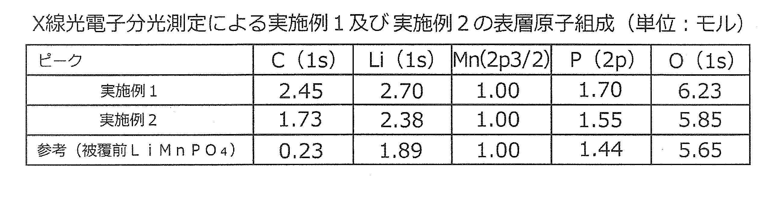
- the surface layer composition of the electrode material of Example 1 (general formula C c Li a Fe x Mn 1 -x P y O z) is a C 2.45 Li 2.70 MnP 1.70 O 6.23 became.
- Table 1 also shows the surface layer composition of the electrode material of Example 2 below, and as a reference sample, was calculated from the X-ray photoelectron spectroscopy results for the LiMnPO 4 substrate before coating the composite layer. The surface layer composition of the LiMnPO 4 substrate is also shown.
- the surface layer composition obtained from the X-ray photoelectron spectroscopic measurement is the bulk composition of LiMnPO 4 crystal (the coefficient a of Li and the coefficient y of P are both 1). ), The coefficient a of Li is 1.89, and the coefficient y of P is 1.44, both of which are excessive compared to Mn. However, in Example 1, the coefficient a of Li is 2.70, and the coefficient y of P is 1.70. Compared to the LiMnPO 4 substrate before coating the composite layer, these ratios in the surface layer of the electrode material are , You can see that it has increased significantly.
- the electrode material of Example 1 contains an amount of Li ion effective for expressing high Li ion conductivity and (poly) phosphate ion, and an amount effective for expressing electron conductivity. It is considered that the transition metal element Mn is also contained. Furthermore, since the electrode material of the present example also includes conductive carbon C having high electronic conductivity in the surface layer, a composite layer containing Li ion conductive material and conductive carbon C is eventually formed on the surface of the primary particles. This corresponds to the coating layer existing in an amorphous state.
- Li coefficient a is 2.5 or more and 3.0 or less and P coefficient y is 1. It exceeds 6 and is 2.0 or less.
- z 6.23
- Formula (2) z [ ⁇ a + xN Fe + (1-x) N Mn + 5y ⁇ / 2] ⁇ From this, the value of “ ⁇ / ⁇ a + xN Fe + (1-x) N Mn + 5y ⁇ ” corresponding to the oxygen deficiency rate in the following formula (3) is calculated as 0.056, and the following formula (3) It was in the range.
- Formula (3) 0.1 ⁇ ⁇ / ⁇ a + xN Fe + (1-x) N Mn + 5y ⁇ ⁇ 0
- N-methylpyrrolidone (NMP) as a dispersion solvent, acetylene black as a conductive auxiliary agent, PVDF (# 9130 manufactured by Kureha Co., Ltd.) as a binder, and electrode material: conductive auxiliary agent : Binder 86.2: 6.8: 7 was added at a mass ratio, and a coating solution diluted with a dispersion solvent was prepared. This coating solution is applied onto an aluminum foil using an automatic coating device (applicator) manufactured by Hosen Co., Ltd., dried and pressed to provide an electrode carrying amount of about 7.0 mg / cm 2 . A positive electrode mixture electrode having a layer thickness of about 40 ⁇ m was produced.
- the positive electrode mixture electrode was assembled with a metal Li foil negative electrode through a porous polyolefin separator, and an electrolyte solution having an ethylene carbonate: ethyl methyl carbonate amount ratio of 3: 7 in which 1 M LiPF 6 was dissolved was used.
- An added 2032 type coin battery was produced.
- Example 2 Below, the manufacturing method of the electrode material of Example 2 is demonstrated.
- the LiMnPO 4 substrate produced in the same manner as in Example 1 the Li ion conductive material and the conductive carbon were formed together with the conductive carbon C in a self-organized manner on the surface layer of the LiMnPO 4 substrate.
- An electrode material provided with a layer containing C was prepared as follows.
- the carbon content in the electrode material of Example 2 was 4.0% by mass.
- the specific surface area by nitrogen adsorption BET multipoint method was 32 m ⁇ 2 > / g, and the area equivalent diameter calculated
- the primary particle diameter is about 50 nm or less, and the average particle diameter calculated from the above-described method for calculating the average body area diameter is about 39 nm.
- Secondary particles secondary particle diameter of about several ⁇ m to several tens of ⁇ m in which a plurality of close primary particles were aggregated and bound were observed.
- FIG. 3 shows the result of powder X-ray diffraction of this electrode material using a Cu—K ⁇ ray source.
- a comparatively broad diffraction peak of LiMnPO 4 crystal as an electrode active material substrate was observed, but it was observed in the LiMnPO 4 electrode active material substrate before the composite layer coating as in Example 1.
- the diffraction peak of the crystal of impurity Li 3 PO 4 was reduced to a trace, and no other diffraction peak of the crystal was observed. From the above, it is considered that the coating layer of the LiMnPO 4 substrate also exists in an amorphous state in this example.
- the DC conductivity of the electrode material measured at 25 ° C. as in Example 1 was 5.7 ⁇ 10 ⁇ 6 S / cm.
- Example 2 X-ray photoelectron spectroscopy (XPS) measurement was performed on the electrode material in the same manner as in Example 1 except that the Fe2p3 narrow scan was omitted.
- Table 1 the surface layer composition of the electrode material of Example 2 (formula C c Li a Fe x Mn 1 -x P y O z) is, C 1.73 Li 2.38 MnP 1.55 O 5.85 next , Li coefficient a was 2.38, and P coefficient y was 1.55. Therefore, the surface layer of the electrode material of Example 2 also has a Li and P ratio that is clearly higher than that of the surface layer of the LiMnPO 4 substrate before coating the composite layer, although not as much as Example 1.
- the electrode material of the present example also includes conductive carbon C having high electronic conductivity in the surface layer, not only the conductive carbon C but also the Li ion conductive material and the conductive material are eventually formed on the surface of the primary particles. This is a composite layer containing crystalline carbon C, which corresponds to the coating layer existing in an amorphous state.
- the formation factor of the Li ion conductive material is not clear, but the LiMnPO 4 substrate and the conductive carbon C layer formed on the surface thereof during firing in the production of the electrode active material of Example 2 As a result of causing some kind of heat-induced reaction, it is presumed that they were formed in a self-organized manner at these interfaces.
- Formula (2) z [ ⁇ a + xN Fe + (1-x) N Mn + 5y ⁇ / 2] ⁇ From this, the value of “ ⁇ / ⁇ a + xN Fe + (1 ⁇ x) N Mn + 5y ⁇ ” corresponding to the oxygen deficiency rate in the following formula (3) is calculated as 0.018, and the following formula (3) It was in the range.
- Formula (3) 0.1 ⁇ ⁇ / ⁇ a + xN Fe + (1-x) N Mn + 5y ⁇ ⁇ 0
- N-methylpyrrolidone (NMP) as a dispersion solvent, acetylene black as a conductive auxiliary agent, PVDF (# 9130 manufactured by Kureha Co., Ltd.) as a binder, and electrode material: conductive auxiliary agent : Binder 86.2: 6.8: 7 was added at a mass ratio, and a coating solution diluted with a dispersion solvent was prepared. This coating solution is applied onto an aluminum foil using an automatic coating device (applicator) manufactured by Hosen Co., Ltd., dried and pressed to provide an electrode carrying amount of about 7.0 mg / cm 2 . A positive electrode mixture electrode having a layer thickness of about 40 ⁇ m was produced.
- the positive electrode mixture electrode was assembled with a metal Li foil negative electrode through a porous polyolefin separator, and an electrolyte solution having an ethylene carbonate: ethyl methyl carbonate amount ratio of 3: 7 in which 1 M LiPF 6 was dissolved was used.
- An added 2032 type coin battery was produced.
- the carbon content in the electrode material of Comparative Example 1 was 4.4% by mass.
- the specific surface area by nitrogen adsorption BET multipoint method was 41 m ⁇ 2 > / g, and the area equivalent diameter calculated
- Formula (1) (Area equivalent diameter) 6 / ⁇ (true density of electrode active material) ⁇ (specific surface area) ⁇
- the results of X-ray diffraction of the electrode material powder were substantially the same as those in Example 2, and there was no significant difference in the position, intensity, relative intensity ratio, half-value width, etc. of the crystal peak corresponding to LiMnPO 4 . Since the X-ray diffraction results and specific surface areas of Example 2 and Comparative Example 1 were substantially the same, the average particle diameters of the primary particles in both were judged to be substantially the same.
- Example 1 ⁇ Rate Characteristic Evaluation of Coin Batteries of Example 1, Example 2 and Comparative Example 1>
- the coin battery of Example 1 was charged at a low current of up to 4.5 V at 0.1 C at 25 ° C. and then charged at a low voltage of 4.5 V (end current 0.01 C), and then 0.1 C.
- the battery was discharged to 2.5V.
- constant current charging and constant voltage charging were performed under the same conditions as described above, and constant current discharging was sequentially performed at 1C, 5C, and 10C, and the rate characteristics were measured.
- the coin battery of Example 1 showed 158 mAh / g at the time of 0.1 C discharge. Further, it showed a very high value of 147 mAh / g at 1 C discharge, 127 mAh / g at 5 C discharge, and further 111 mAh / g at 10 C discharge. Further, from FIG. 5, the coin battery of Example 2 showed 146 mAh / g at the time of 0.1 C discharge. Moreover, although it was inferior to the coin battery of Example 1 of 126 mAh / g at the time of 1 C discharge and 93 mAh / g at the time of 5 C discharge and 67 mAh / g at the time of 10 C discharge, it showed a high value. On the other hand, from FIG. 6, the coin battery of Comparative Example 1 remained at 136 mAh / g at the time of 0.1 C discharge. In addition, at the time of 0.01 C discharge, 152 mAh / g was shown.
- the symmetry of the discharge curve on the charge side and the discharge side in charge / discharge at 0.1 C is similar to that of the coin battery of Example 2 and Comparative Example 1 in the coin battery of Example 1. Compared to this, the discharge side is particularly improved. From these results, the coin battery of Example 1 and the coin battery of Example 2 were superior in rate characteristics than the coin battery of Comparative Example 1, and in particular, Example 1 gave very excellent results.
Abstract
Description
また、特許文献2には、Li、M、P及びO(ただし、MはFe、Mn、Co及びNiの少なくともいずれか1つ)を含むコアを、NとCの少なくとも一方と、Li、M、P及びOとを含む酸化物コーティングでコーティングした粒子が開示されている。この事例では、該酸化物コーティングによってLiイオン伝導性(拡散性)が補われ、高い入出力特性を発現させる態様が示されている。
一方、特許文献3には、導電性炭素とLiイオン伝導性物質とからなる複合コート層を前記電極活物質の表面にコートした電極材料が開示されている。
特許文献1及び特許文献2で開示されている電極活物質を使用しても、電子伝導性とリチウムイオン伝導性とはトレードオフの関係にあり、この両者を両立することは困難な場合があった。
一方、特許文献3で開示されている電極活物質では、導電性炭素とLiイオン伝導性物質とからなる複合コート層を前記電極活物質の表面にコートすることにより、電子伝導性とLiイオン伝導性の両方を向上させている。
特許文献1、特許文献2及び特許文献3には塗工性の悪化や塗工層の劣化に関する記載はなく、これらを解決する手段についての記載はない。
式(1)
(面積相当径)=6/{(電極活物質の真密度)×(比表面積)}
本明細書では、一般式LiMPO4とは、Li:M:P:Oが大凡1:1:1:4となる数の割合で各成分を含有していることを意味する。すなわち、厳密に1:1:1:4の割合で各成分を含有していることや不純物を全く含まないことまでは要求していない。
また、本態様によれば、前記一次粒子が前記Liイオン伝導性物質と導電性炭素Cとを含む層を介して結着され、緻密な二次粒子を形成しているので、Liイオンは該層を介してある一次粒子から別の一次粒子へと二次元または三次元的に移動可能となり、Liイオン伝導性を高くすることができる。また、導電性炭素Cを含む層を介してある一次粒子から別の一次粒子へと電子が移動可能となるので、電子伝導性を高くすることができる。すなわち、電子伝導性とリチウムイオン伝導性との両立性をさらに向上可能である。
(ただし、cは0.5以上4以下の数、aは2以上4以下の数、xは0以上1以下の数、yは1以上3以下の数である。また、zは下記式(2)で表される数である。さらに、δは、FeおよびMnの平均価数NFe及びNMnが共に2であると仮定した場合に、下記式(3)を満たす数である)
式(2)
z=[{a+xNFe+(1-x)NMn+5y}/2]-δ
式(3)
0.1≧δ/{a+xNFe+(1-x)NMn+5y}≧0
さらに本態様においては、導電性炭素Cも電子伝導性の付与に有効な量比で含まれる。
これらのため、こうしたLiイオン伝導性物質と導電性炭素Cとを含む層を備える前記電極材料は、良好な充放電特性を示す。
なお、「取出し角度が53±10度」とは、厳密な意味での「53±10度」に限定されずその周辺値をも含む意味である。
また、本態様の電極材料においては、電極活物質の一次粒子の平均粒径が20nm以上である。これより一次粒子の平均粒径が小さいと電極活物質が変質し、充放電容量が低下する。
なお、「最大二次粒径が20μm以下」とは厳密な意味での「20μm以下」に限定されずその周辺値をも含む意味である。また、「60MPaにて圧縮した状態における25℃での前記電極材料の直流導電率」とは厳密な意味での「60MPa」及び「25℃」に限定されずその周辺値における「前記電極材料の直流導電率」をも含む意味である。
本態様によれば、前記層はアモルファス層であるので、Liイオンは該層を三次元的に移動可能となり、Liイオン伝導性がさらに高い。すなわち、電子伝導性とリチウムイオン伝導性との両立性をさらに向上可能である。
式(1)
(面積相当径)=6/{(電極活物質の真密度)×(比表面積)}
また、「前記混合工程2で得られる混合物と導電性炭素C源となる原料とを分散及び混合し、さらに1μm以上50μm以下の凝集粒径になるように造粒する」とは厳密な意味での「0.1μm以下の粒度」及び「1μm以上50μm以下の凝集粒径」に限定されずその周辺値をも含む意味である。
本発明の電極材料における電極活物質は、一般式LiMPO4(ただし、M=[FetMn1-t]であり、tは0以上1以下の数である)で表され、電気化学的酸化又は還元に伴ってLiイオンを放出又は吸蔵する。そして、前記酸化又は還元の過程で、結晶格子内部で一次元の許容移動方向のみを前記カチオンが移動し得る結晶構造を有する。
また、本発明の電極材料においては、一次粒子の平均粒径が20nm以上である。これより一次粒子の平均粒径が小さいと電極活物質が変質し、充放電容量が低下する。
本発明の材料は、一般式LiMPO4(ただし、M=[FetMn1-t]であり、tは0以上1以下の数である)で表される電極活物質の一次粒子の表面に、Liと、Fe及びMnの内の少なくとも何れか1つと、P及びOとを含むLiイオン伝導性物質と、導電性炭素Cと、を含む層を備えるものが用いられる。
さらに好ましくは、Liイオン伝導性物質を含む層は、Liイオンの拡散移動に基づく10-8S/cm相当以上のイオン伝導性と、10-8S/cm以上の電子伝導性を有する。さらに一層好ましくは、10-6S/cm相当以上の前記イオン伝導性と、10-6S/cm相当以上の電子伝導性を有する。この電子伝導性は、該Liイオン伝導性物質が遷移金属元素(ここではFe及びMnの内の少なくとも何れか1つ)を一定量以上含有することによってもたらされ得る。
こうしたLiイオン伝導性物質としては、Fe及びMnが部分置換した(ポリ)リン酸塩の基本組成を有する物質、及びこれらの内の複数が複合した以下のような化合物が挙げられる(以下において、rは1以下、好ましくはおよそ0.3以下の正の数であり、Liの係数は正の数)。
Li3-2rFe(II)rPO4、Li2-2rFe(II)rP2O7、
Li3-3rFe(III)rPO4、Li2-3rFe(III)rP2O7、
Li9-4rFe(II)2r(PO4)3、Li9-6rFe(III)2r(PO4)3
等。
Li3-2rMn(II)rPO4、Li2-2rMn(II)xP2O7、
Li3-3rMn(III)rPO4、Li2-3rMn(III)rP2O7、
Li9-4rMn(II)2r(PO4)3、Li9-6rMn(III)2r(PO4)3
等。
導電性炭素C源となる原料としては、少なくとも部分的な溶融状態から加熱分解を受けて導電性炭素を生じるタール及び石炭ピッチなどのビチューメン類、芳香族化合物、鎖状炭化水素、またはそれらの誘導体、デキストリン等の糖類又はその誘導体等を用いることができる。
本発明の電極材料は、一般式LiMPO4(ただしM=[FetMn1-t]であり、ここでtは0以上1以下の数)で表される電極活物質の一次粒子の表面に、Liと、Fe及びMnの内の少なくとも何れか1つとP及びOとを含むLiイオン伝導性物質と導電性炭素Cとを含む層を備える。その層厚は、高分解能透過型電子顕微鏡、または前述したこれと同等の分解能を有する構造評価手段による観察において、0.6nm以上5nm以下であることが好ましい。
なお、この表面層は、高分解能の透過型電子顕微鏡等を用いてアモルファス層になっているか否かを確認することが可能である。
次に、本発明の電極材料の外観について模式図及び透過電子顕微鏡写真に基づいて説明する。
図1は、本発明の一実施例に係る電極材料の模式図を示している。
また、電極活物質LiMPO4の一次粒子2の内部においては、Liイオンは方向Aの一次元にしか移動することはできない。ただし、内層3及び外層4では、Liイオンは二次元的または三次元的に移動することが可能である。
式(1)
(面積相当径)=6/{(電極活物質の真密度)×(比表面積)}
これらの電極材料においては、該電局材料を構成する一次粒子の外部に露出する表面が上記の比表面積以下に限られることに相当する。このため、該電極材料を電池の電極に用いる場合、集電金属箔上への塗工用分散液を作成する際に、該電極材料の量比を多くしても、塗工用分散液中に添加されたPVDF等の極性ポリマーバインダーとの相互作用を抑制でき、その結果と工用分散液の粘度を低く抑えることができる。これにより、塗工性の悪化や塗工層の劣化を抑制することができる。
(ただし、cは0.5以上4以下の数、aは2以上4以下の数、xは0以上1以下の数、yは1以上3以下の数である。また、zは下記式(2)で表される数である。さらに、δは、FeおよびMnの平均価数NFe及びNMnが共に2であると仮定した場合に、下記式(3)を満たす数である)
式(2)
z=[{a+xNFe+(1-x)NMn+5y}/2]-δ
式(3)
0.1≧δ/{a+xNFe+(1-x)NMn+5y}≧0
また、上記電極材料の好ましい態様では、前記前記X線光電子分光測定から算出される前記表層組成の一般式CcLiaFexMn1-xPyOzにおいて、aは2.0以上3.0以下であり、yは1.5以上1.6以下である。さらに好ましくは、aは2.5以上3.0以下であり、かつyは1.6を越え2.0以下である。
これらのa及びyを有する電極材料では、前記Liイオン伝導性物質が特に優れたLiイオン伝導性を有し、かつ有効な電子伝導性も兼ね備えるため、該Liイオン伝導性物質と導電性炭素Cとを含む層を備える該電極材料は、特に良好な充放電特性を示す。
その結果、比表面積から算出される面積相当径が増大するため、該面積相当径よりも電極活物質の一次粒子の平均粒径は小さくなる。また、本電極材料を電池の電極として用いる場合には、前記BET比表面積測定に用いる窒素と同様、該結着部位には電極塗工用分散液も浸入・接触しないため、該結着部位では塗工用分散液中に添加されるPVDF等の極性ポリマーバインダーとの相互作用が生じにくいので、塗工用分散液の粘度上昇が抑制され、塗工層の劣化を防止できる。
なお、本発明の電極材料においては、前記Liイオン伝導性物質と導電性炭素とを含む層を介さずに、電極活物質の一次粒子同士が直接互いに接合・結着した部位を含む場合もある。こうした結着部位においても、前述のBET比表面積測定に用いた窒素ガスは接触・吸着せず、その分、BET多点法測定によって測定される比表面積が減少し、面積相当径が増大するため、該面積相当径よりも一次粒子の平均粒径は小さくなる。しかし、こうした結着部位ではLiイオン伝導性及び電子伝導性は付与されないため、電極材料としては機能しにくい。このため、前記一次粒子同士が互いに直接接合・結着した部位は、本発明の電極材料において存在してもよいが、前記Liイオン伝導性物質と導電性炭素とを含む層を介した結着部位より少ないことが好ましい。その具体的な判断基準としては、例えば、高分解能透過型電子顕微鏡による該電極材料における一次粒子間の結着部位を複数箇所について観察し、これらの観察像において、前記Liイオン伝導性物質と導電性炭素とを含む層を介した結着部位の投影長さの総和より、前記一次粒子同士が互いに直接接合・結着した部位の投影長さの総和が短くなることが好ましい。
ただし、上記tが0.2未満の場合は、前記面積相当径が70nm以下であることが必要であり、より好ましくは60nm以下である。上記tが0.2未満の場合、電極活物質内におけるLiイオン伝導性が極めて乏しくなり、その比表面積が小さ過ぎると、該電極材料を電池の構成部材として電池を組んだ場合に、電池内に封入される電解液等のLiイオン伝導媒体と該電極材料との間の接触界面が不足する。その結果、上述のLiイオン伝導性物質を含む層を備えた電極活物質からなる該電極材料をもってしても、良好な電池特性は得られにくくなる。これに対し、面積相当径が上記の値以下となる電極材料においては、前記面積相当径が十分小さく、従って比表面積が十分大きいので、前記接触界面が十分確保できるため、良好な電池特性が得られる。
なお、上記Mの係数tが0.2以上0.8以下、すなわちMの2割以上8割以下がFeである場合は、良好な電池特性を得るためには、前記面積相当径が85nm以下であることが好ましい。また、上記Mの係数tが0.8を超える、すなわちMの8割を超える割合がFeである場合は、良好な電池特性を得るためには、前記面積相当径が130nm以下であることが好ましい。
以下に、実施例1の製造方法を説明する。
なお、下記の実施例1では、電極活物質LiMPO4のMは、M=[FetMn1-t]であり、その係数tは推算で約0.03、また、実施例2及び比較例1では0であり、いずれもMはMn単独か、またはそれに近い。
まず、試薬LiOH・H2Oの室温で飽和に近い水溶液(以下、Li源水溶液)と、試薬MnSO4の室温で飽和に近い水溶液(以下、Mn源水溶液)と、試薬85%リン酸と試薬ジメチルスルホキシド(DMSO)及び水の混合溶液(以下、P源DMSO水溶液)と、を総括のLi、Mn、Pの元素モル比が3:1:1となるように、それぞれ所定量ずつ調製した。ここで、前記P源DMSO水溶液中のDMSO及び水の量は、これらの原料溶液を全て混合した後の溶液中の水:DMSOの割合が1:1程度となるように定めた。
前記LiMnPO4の電極活物質基体の比表面積は59m2/g(面積相当径30nm)で、透過型電子顕微鏡観察では細長い一次粒子結晶が認められ、その長径は約50nm内外、短径は約15nm内外だった。
まず、Liイオン伝導性物質の原料として、0.23gの試薬酢酸リチウムを含有する0.1M水溶液と、1.51gの試薬シュウ酸鉄(III)アンモニウム三水和物を含有する0.1M水溶液とを調製した。次に、20gの前記LiMnPO4基体に、前記酢酸リチウム水溶液及びシュウ酸鉄(III)アンモニウム三水和物水溶液を添加・混合し、水を留去した後、1.87gの試薬リン酸トリブチルを少量のエタノールと共に添加・混合し、エタノールを乾燥除去することにより、Liイオン伝導性物質の原料混合物を得た。次に、この混合物23.55gに対して、導電性炭素の前駆物質として、1.08gのJFEケミカル(株)製250℃軟化ピッチMCP-250Dを添加した後、(株)シンキー製自転・公転ミキサーARE-310を用いて混合・造粒し、約1~30μm程度の範囲の二次粒径を有するこれらの混合物を得た。これを窒素気流下で約710℃にて焼成し、Liイオン伝導性物質と導電性炭素Cとを含む複合層を被覆した電極材料を得た。
式(1)
(面積相当径)=6/{(電極活物質の真密度)×(比表面積)}
また、この電極材料を最大二次粒径が約20μm以下となるように粉砕後、かつ約60MPaにて圧縮した状態における25℃での前記電極材料の直流導電率は、4.8×10⁻⁴S/cmであり、電子伝導性を有していた。
測定装置には、サーモフィッシャーサイエンティフィック(株)製のVG Theta-Probeを用いた。実施例1の電極材料を平板ペレット状に圧縮成形し、該ペレット状の平板面に単結晶分光Al-Kαを線源とするX線を照射し、該ペレット状の平板面に対し鉛直及び水平方向をそれぞれ0及び90度とした場合の取出し角度約53度(固定角モード)にて、X線光電子分光測定を行った。測定においては、C1s、Li1s、Fe2p3/2、Mn2p3/2、P2p及びO1sの各電子軌道のナロースキャンを実施し、これらの分光結果から算出される前記電極材料の表層の元素組成を算出した。この結果を表1に示す。
なお、Fe2p3/2軌道のピークは痕跡程度であり、その濃度は、Mnに対しおよそ0.1モル%オーダーの量であると見なされた。大半のFeは、おそらくは焼成工程中に電極活物質基体内部に拡散移行し、Mnの一部と置換したと思われる。
表1から、実施例1の電極材料の表層組成(一般式CcLiaFexMn1-xPyOz)は、C2.45Li2.70MnP1.70O6.23となった。
なお、表1には、併せて、下記の実施例2の電極材料の表層組成を示すとともに、参考用試料として、前記複合層を被覆する前のLiMnPO4基体に対するX線光電子分光結果から算出された、LiMnPO4基体の表層組成も示す。
また、前述の下記式(2)から、z=6.23とし、xが略0でMnの平均価数NMnが2であると仮定して、Oの欠損に相当するδを求めるとδ=0.37となる。
式(2)
z=[{a+xNFe+(1-x)NMn+5y}/2]-δ
これより、前述の下記式(3)における、酸素欠損率に相当する「δ/{a+xNFe+(1-x)NMn+5y}」の値は0.056と算出され、下記式(3)の範囲内にあった。
式(3)
0.1≧δ/{a+xNFe+(1-x)NMn+5y}≧0
なお、前述の混合・造粒条件のみ調整し、面積相当径を変化させた場合、面積相当径が50nm以下では前述の良好な塗工性を概ね維持できた。
以下に、実施例2の電極材料の製造方法を説明する。
実施例1と同様に作製したLiMnPO4基体に対し、導電性炭素Cと共に、Liイオン伝導性物質をLiMnPO4基体の表層において自己組織的に形成させることにより、Liイオン伝導性物質と導電性炭素Cとを含む層を備えた電極材料を以下の要領で作製した。
走査型電子顕微鏡及び透過型電子顕微鏡観察では、実施例1と同様に、一次粒子径約50nm以下で、前述の体面積平均径の算出方法から算出された平均粒径が約39nmの、球状に近い複数の一次粒子が凝集・結着した二次粒子(二次粒子径は数μm~10数μm程度)が見られた。従って実施例2の電極材料も、一次粒子径及び面積相当径の観点からは、前述した本発明の特に好ましい態様に相当する、「20nm≦一次粒子径≦面積相当径、及び45nm≦面積相当径≦60nm」の関係を満たしている。
また、透過型電子顕微鏡による高分解能観察でも、実施例1と同様に、一次粒子の表面に、結晶格子縞が認められない約2nmの厚さの被覆層が、ほぼ一次粒子像のほぼ全周に亘って認められた。
式(1)
(面積相当径)=6/{(電極活物質の真密度)×(比表面積)}
また、実施例1と同様に測定した25℃での前記電極材料の直流導電率は、5.7×10⁻⁶S/cmであった。
表1から、実施例2の電極材料の表層組成(一般式CcLiaFexMn1-xPyOz)は、C1.73Li2.38MnP1.55O5.85となり、Liの係数aは2.38、Pの係数yは1.55であった。従って実施例2の電極材料の表層においても、実施例1ほどではないが、前記複合層を被覆する前のLiMnPO4基体の表層よりも明らかに高いLi及びPの割合を有している。
以上において、Liイオン伝導性物質の形成要因は明らかではないが、実施例2の電極活物質製造の際の焼成中に、LiMnPO4基体と、その表面上に形成される導電性炭素Cの層との間で何らかの加熱誘発反応を生じた結果、これらの界面で自己組織化的に形成されたと推定される。
また、前述の下記式(2)から、z=5.85とし、xが0でMnの平均価数NMnが2であると仮定して、Oの欠損に相当するδを求めるとδ=0.215となる。
式(2)
z=[{a+xNFe+(1-x)NMn+5y}/2]-δ
これより、前述の下記式(3)における、酸素欠損率に相当する「δ/{a+xNFe+(1-x)NMn+5y}」の値は0.018と算出され、下記式(3)の範囲内にあった。
式(3)
0.1≧δ/{a+xNFe+(1-x)NMn+5y}≧0
以下に、比較例1の電極材料の製造方法を説明する。
実施例2と同様のLiイオン伝導性物質と導電性炭素Cとを含む層を備えるが、面積相当径が本発明の態様よりも大きく、二次粒子が無定形な電極材料を以下の要領で作製した。
式(1)
(面積相当径)=6/{(電極活物質の真密度)×(比表面積)}
実施例2及び比較例1のX線回折結果及び比表面積が略同一であることから、両者における一次粒子の平均粒径は略同一であると判断された。
上記の実施例1のコイン電池に対し、25℃において、0.1Cにて4.5Vまで低電流充電後、4.5Vで低電圧充電を行い(終止電流0.01C)、その後0.1Cにて2.5Vまで放電させた。これに続けて、上記と同様の条件で定電流充電及び定電圧充電を行い、1C、5C及び10Cにて逐次定電流放電させ、レート特性を測定した。
これらの結果を図4に示す。
これらの結果を図5に示す。
これらの結果を図6に示す。
また図5より、実施例2のコイン電池は、0.1C放電時において146mAh/gを示した。また、1C放電時において126mAh/g、5C放電時において93mAh/g、10C放電時において67mAh/gという、実施例1のコイン電池よりは劣るが、高い値を示した。
一方、図6より、比較例1のコイン電池は、0.1C放電時において136mAh/gに留まった。なお、0.01C放電時においては、152mAh/gを示した。
これらの結果から、実施例1のコイン電池及び実施例2のコイン電池は、比較例1のコイン電池よりもレート特性に優れており、特に実施例1では非常に優れた結果が得られた。
Claims (12)
- 一般式LiMPO4(ただし、M=[FetMn1-t]であり、tは0以上1以下の数である)で表される電極活物質の一次粒子の表面に、
Liと、Fe及びMnの内の少なくとも何れか1つと、P及びOと、を含むLiイオン伝導性物質と、
導電性炭素Cと、を含む層を備え、
複数の前記一次粒子が凝集し、前記Liイオン伝導性物質と導電性炭素Cとを含む層を介して該一次粒子同士が結着されてなる緻密な二次粒子を含み、
窒素吸着ブルナウアー・エメット・テーラー(BET)多点法による比表面積から下記式(1)によって求められる面積相当径が45nm以上であることを特徴とする電極材料。
式(1)
(面積相当径)=6/{(電極活物質の真密度)×(比表面積)} - 請求項1に記載の電極材料において、
平板ペレット状に圧縮成形された際の平板面に単結晶分光Al-KαのX線を照射し、該平板面に対し鉛直及び水平方向をそれぞれ0及び90度とした場合の取出し角度が53±10度にて得られるX線光電子分光測定において、C1s、Li1s、Fe2p3/2、Mn2p3/2、P2p及びO1sの各電子軌道のナロースキャン結果から算出される表層組成が、一般式CcLiaFexMn1-xPyOzで表されることを特徴とする電極材料。
(ただし、cは0.5以上4以下の数、aは2以上4以下の数、xは0以上1以下の数、yは1以上3以下の数である。また、zは下記式(2)で表される数である。さらに、δは、FeおよびMnの平均価数NFe及びNMnが共に2であると仮定した場合に、下記式(3)を満たす数である)
式(2)
z=[{a+xNFe+(1-x)NMn+5y}/2]-δ
式(3)
0.1≧δ/{a+xNFe+(1-x)NMn+5y}≧0 - 請求項2に記載の電極材料において、
前記一般式CcLiaFexMn1-xPyOzにおいて、aは2.0以上3.0以下であり、かつyは1.5以上1.6以下であることを特徴とする電極材料。 - 請求項2に記載の電極材料において、
前記一般式CcLiaFexMn1-xPyOzにおいて、aは2.5以上3.0以下であり、かつyは1.6を越え2.0以下であることを特徴とする電極材料。 - 請求項1から4のいずれか1項に記載の電極材料において、
前記一次粒子の平均粒径は20nm以上であり、かつ前記面積相当径未満であることを特徴とする電極材料。 - 請求項1から5のいずれか1項に記載の電極材料において、
最大二次粒径が20μm以下となるように粉砕後、60MPaにて圧縮した状態における25℃での前記電極材料の直流導電率が、10-6S/cm以上であることを特徴とする電極材料。 - 請求項1から6のいずれか1項に記載の電極材料において、
前記M=[FetMn1-t]において、tは0.2未満であることを特徴とする電極材料。 - 請求項7に記載の電極材料において、
前記面積相当径は70nm以下であることを特徴とする電極材料。 - 請求項8に記載の電極材料において、
前記面積相当径は60nm以下であることを特徴とする電極材料。 - 請求項1から9のいずれか1項に記載の電極材料において、
前記Liイオン伝導性物質と導電性炭素Cとを含む層はアモルファス層であることを特徴とする電極材料。 - 請求項1から10のいずれか1項に記載の電極材料において、
前記面積相当径は50nm以上であることを特徴とする電極材料。 - 一般式LiMPO4(ただし、M=[FetMn1-t]であり、tは0以上1以下の数である)で表される微粉体状の電極活物質基体と、Liイオン源となる原料と、Feイオン及びMnイオンの内の少なくとも何れか1つのイオン源となる原料と、を分散及び混合する混合工程1と、
前記混合工程1で得られる混合物と、リン酸イオン源または多価リン酸イオン源となる原料と、を分散及び混合する混合工程2と、
前記混合工程2で得られる混合物と導電性炭素C源となる原料とを分散及び混合し、さらに1μm以上50μm以下の凝集粒径になるように緻密に造粒する混合及び造粒工程と、
前記一般式LiMPO4で表される微粉状の電極活物質基体の一次粒子の表面に、
Liと、Fe及びMnの内の少なくとも何れか1つと、P及びOとを含むLiイオン伝導性物質と、
導電性炭素Cと、を含む層が生成するように、前記混合及び造粒工程で得られる混合物を焼成する焼成工程と、を含むことを特徴とする電極材料の製造方法。
Priority Applications (4)
| Application Number | Priority Date | Filing Date | Title |
|---|---|---|---|
| US14/442,054 US20150311510A1 (en) | 2012-11-12 | 2013-11-08 | Electrode material and method for producing electrode material |
| EP13853235.3A EP2919303A4 (en) | 2012-11-12 | 2013-11-08 | ELECTRODE MATERIAL AND METHOD FOR PRODUCING AN ELECTRODE MATERIAL |
| CN201380058987.6A CN104781965B (zh) | 2012-11-12 | 2013-11-08 | 电极材料和电极材料的生产方法 |
| JP2014545774A JP6309456B2 (ja) | 2012-11-12 | 2013-11-08 | 電極材料及び電極材料の製造方法 |
Applications Claiming Priority (2)
| Application Number | Priority Date | Filing Date | Title |
|---|---|---|---|
| JP2012248859 | 2012-11-12 | ||
| JP2012-248859 | 2012-11-12 |
Publications (1)
| Publication Number | Publication Date |
|---|---|
| WO2014073652A1 true WO2014073652A1 (ja) | 2014-05-15 |
Family
ID=50684743
Family Applications (1)
| Application Number | Title | Priority Date | Filing Date |
|---|---|---|---|
| PCT/JP2013/080293 WO2014073652A1 (ja) | 2012-11-12 | 2013-11-08 | 電極材料及び電極材料の製造方法 |
Country Status (6)
| Country | Link |
|---|---|
| US (1) | US20150311510A1 (ja) |
| EP (1) | EP2919303A4 (ja) |
| JP (1) | JP6309456B2 (ja) |
| KR (1) | KR20150084995A (ja) |
| CN (1) | CN104781965B (ja) |
| WO (1) | WO2014073652A1 (ja) |
Cited By (5)
| Publication number | Priority date | Publication date | Assignee | Title |
|---|---|---|---|---|
| JP2014209434A (ja) * | 2013-03-25 | 2014-11-06 | 住友大阪セメント株式会社 | 電極材料及び電極並びにリチウムイオン電池 |
| JP2017059302A (ja) * | 2015-09-14 | 2017-03-23 | 株式会社東芝 | 電極、非水電解質電池および電池パック |
| JP2017220318A (ja) * | 2016-06-06 | 2017-12-14 | トヨタ自動車株式会社 | 複合活物質 |
| JP2018147555A (ja) * | 2017-03-01 | 2018-09-20 | 太平洋セメント株式会社 | リチウムイオン二次電池用正極活物質複合体、及びその製造方法 |
| JP6471821B1 (ja) * | 2018-02-28 | 2019-02-20 | 住友大阪セメント株式会社 | リチウムイオン二次電池用電極材料、リチウムイオン二次電池用電極、及びリチウムイオン二次電池 |
Families Citing this family (5)
| Publication number | Priority date | Publication date | Assignee | Title |
|---|---|---|---|---|
| CN107810571B (zh) * | 2015-06-26 | 2021-12-10 | A123系统有限责任公司 | 用于高功率应用的纳米级孔结构阴极和材料合成方法 |
| CN108530053B (zh) * | 2018-03-30 | 2021-03-30 | 华南理工大学 | 一种pH值敏感变色无机材料及其制备方法 |
| US20220384806A1 (en) * | 2019-10-04 | 2022-12-01 | Sanyo Electric Co., Ltd. | Positive electrode active material for non-aqueous electrolyte secondary batteries, and non-aqueous electrolyte secondary battery |
| US11424445B1 (en) * | 2021-05-30 | 2022-08-23 | Marvin S Keshner | Solid-state rechargeable lithium battery with solid-state electrolyte |
| JP2023122200A (ja) * | 2022-02-22 | 2023-09-01 | トヨタ自動車株式会社 | 複合粒子、正極、全固体電池、および複合粒子の製造方法 |
Citations (18)
| Publication number | Priority date | Publication date | Assignee | Title |
|---|---|---|---|---|
| JPH09134724A (ja) | 1995-11-07 | 1997-05-20 | Nippon Telegr & Teleph Corp <Ntt> | 非水電解質二次電池 |
| JP2002151082A (ja) | 2000-11-10 | 2002-05-24 | Kansai Research Institute | 鉄リン酸リチウム及びその製造方法並びにこれを用いた二次電池 |
| JP2003157845A (ja) | 2001-11-22 | 2003-05-30 | Kyushu Univ | 2次電池用正極材料の製造方法、および2次電池 |
| JP2004063386A (ja) | 2002-07-31 | 2004-02-26 | Mitsui Eng & Shipbuild Co Ltd | 2次電池正極材料の製造方法、および2次電池 |
| JP2004095385A (ja) | 2002-08-30 | 2004-03-25 | Sumitomo Osaka Cement Co Ltd | リチウムイオン電池用正極材料の製造方法およびリチウムイオン電池 |
| JP2007119304A (ja) | 2005-10-28 | 2007-05-17 | Toyota Motor Corp | LiMnPO4の製造方法 |
| JP2007213961A (ja) * | 2006-02-09 | 2007-08-23 | Sanyo Electric Co Ltd | 非水電解質二次電池 |
| JP2010500113A (ja) | 2006-08-07 | 2010-01-07 | ゴア エンタープライズ ホールディングス,インコーポレイティド | 膨張性吸収ポリマーデバイス |
| JP4465412B2 (ja) | 2006-12-22 | 2010-05-19 | ユミコア ソシエテ アノニム | 電気活性な結晶質ナノメトリックLiMnPO4粉末の合成 |
| JP2010517240A (ja) | 2007-01-25 | 2010-05-20 | マサチューセッツ インスティテュート オブ テクノロジー | 酸化リチウム粒子上の酸化コーティング |
| JP2011076820A (ja) * | 2009-09-30 | 2011-04-14 | Hitachi Vehicle Energy Ltd | リチウム二次電池及びリチウム二次電池用正極 |
| WO2011091525A1 (fr) * | 2010-01-28 | 2011-08-04 | Phostech Lithium Inc. | Procede d'optimisation d'un materiau de cathode et materiau de cathode ayant des propriétés électrochimiques améliorées |
| JP2011181375A (ja) | 2010-03-02 | 2011-09-15 | Sumitomo Osaka Cement Co Ltd | 電極活物質及びリチウムイオン電池 |
| WO2011131553A2 (de) * | 2010-04-23 | 2011-10-27 | Süd-Chemie AG | Kohlenstoffhaltiges verbundmaterial enthaltend eine sauerstoffhaltige lithium-übergangsmetallverbindung |
| WO2012052811A1 (en) * | 2010-10-20 | 2012-04-26 | Council Of Scientific & Industrial Research | Process for the preparation of high voltage nano composite cathode (4.9v) for lithium ion batteries |
| WO2012133566A1 (ja) | 2011-03-28 | 2012-10-04 | 兵庫県 | 二次電池用電極材料、二次電池用電極材料の製造方法および二次電池 |
| JP2013077392A (ja) * | 2011-09-29 | 2013-04-25 | Panasonic Corp | 蓄電材料及び蓄電デバイス |
| JP2013152932A (ja) * | 2012-01-17 | 2013-08-08 | Hutchinson Sa | リチウムイオン電池のセルのカソード、その製造プロセスおよびこれを組み込んだ電池 |
Family Cites Families (8)
| Publication number | Priority date | Publication date | Assignee | Title |
|---|---|---|---|---|
| JP3921931B2 (ja) | 2000-09-29 | 2007-05-30 | ソニー株式会社 | 正極活物質及び非水電解質電池 |
| US7939201B2 (en) * | 2005-08-08 | 2011-05-10 | A123 Systems, Inc. | Nanoscale ion storage materials including co-existing phases or solid solutions |
| CN100563047C (zh) | 2006-04-25 | 2009-11-25 | 立凯电能科技股份有限公司 | 适用于制作二次电池的正极的复合材料及其所制得的电池 |
| JP5223281B2 (ja) * | 2007-09-28 | 2013-06-26 | Tdk株式会社 | リチウムイオン二次電池又はリチウム二次電池の正極用複合粒子、及びリチウムイオン二次電池又はリチウム二次電池 |
| KR101105879B1 (ko) * | 2009-08-28 | 2012-01-16 | 주식회사 코캄 | 리튬 이차전지용 양극 활물질 및 그 제조방법과 이를 포함하는 리튬 이차전지 |
| KR101253319B1 (ko) * | 2010-09-10 | 2013-04-10 | 국립대학법인 울산과학기술대학교 산학협력단 | 리튬 이차 전지용 양극 활물질, 이의 제조방법 및 이를 포함하는 리튬 이차 전지 |
| JP2012185979A (ja) * | 2011-03-04 | 2012-09-27 | Sumitomo Osaka Cement Co Ltd | 電極活物質の製造方法 |
| JP5529217B2 (ja) | 2012-07-17 | 2014-06-25 | 株式会社日立製作所 | 半導体装置の製造方法 |
-
2013
- 2013-11-08 JP JP2014545774A patent/JP6309456B2/ja not_active Expired - Fee Related
- 2013-11-08 KR KR1020157015544A patent/KR20150084995A/ko not_active Application Discontinuation
- 2013-11-08 CN CN201380058987.6A patent/CN104781965B/zh not_active Expired - Fee Related
- 2013-11-08 EP EP13853235.3A patent/EP2919303A4/en not_active Withdrawn
- 2013-11-08 US US14/442,054 patent/US20150311510A1/en not_active Abandoned
- 2013-11-08 WO PCT/JP2013/080293 patent/WO2014073652A1/ja active Application Filing
Patent Citations (18)
| Publication number | Priority date | Publication date | Assignee | Title |
|---|---|---|---|---|
| JPH09134724A (ja) | 1995-11-07 | 1997-05-20 | Nippon Telegr & Teleph Corp <Ntt> | 非水電解質二次電池 |
| JP2002151082A (ja) | 2000-11-10 | 2002-05-24 | Kansai Research Institute | 鉄リン酸リチウム及びその製造方法並びにこれを用いた二次電池 |
| JP2003157845A (ja) | 2001-11-22 | 2003-05-30 | Kyushu Univ | 2次電池用正極材料の製造方法、および2次電池 |
| JP2004063386A (ja) | 2002-07-31 | 2004-02-26 | Mitsui Eng & Shipbuild Co Ltd | 2次電池正極材料の製造方法、および2次電池 |
| JP2004095385A (ja) | 2002-08-30 | 2004-03-25 | Sumitomo Osaka Cement Co Ltd | リチウムイオン電池用正極材料の製造方法およびリチウムイオン電池 |
| JP2007119304A (ja) | 2005-10-28 | 2007-05-17 | Toyota Motor Corp | LiMnPO4の製造方法 |
| JP2007213961A (ja) * | 2006-02-09 | 2007-08-23 | Sanyo Electric Co Ltd | 非水電解質二次電池 |
| JP2010500113A (ja) | 2006-08-07 | 2010-01-07 | ゴア エンタープライズ ホールディングス,インコーポレイティド | 膨張性吸収ポリマーデバイス |
| JP4465412B2 (ja) | 2006-12-22 | 2010-05-19 | ユミコア ソシエテ アノニム | 電気活性な結晶質ナノメトリックLiMnPO4粉末の合成 |
| JP2010517240A (ja) | 2007-01-25 | 2010-05-20 | マサチューセッツ インスティテュート オブ テクノロジー | 酸化リチウム粒子上の酸化コーティング |
| JP2011076820A (ja) * | 2009-09-30 | 2011-04-14 | Hitachi Vehicle Energy Ltd | リチウム二次電池及びリチウム二次電池用正極 |
| WO2011091525A1 (fr) * | 2010-01-28 | 2011-08-04 | Phostech Lithium Inc. | Procede d'optimisation d'un materiau de cathode et materiau de cathode ayant des propriétés électrochimiques améliorées |
| JP2011181375A (ja) | 2010-03-02 | 2011-09-15 | Sumitomo Osaka Cement Co Ltd | 電極活物質及びリチウムイオン電池 |
| WO2011131553A2 (de) * | 2010-04-23 | 2011-10-27 | Süd-Chemie AG | Kohlenstoffhaltiges verbundmaterial enthaltend eine sauerstoffhaltige lithium-übergangsmetallverbindung |
| WO2012052811A1 (en) * | 2010-10-20 | 2012-04-26 | Council Of Scientific & Industrial Research | Process for the preparation of high voltage nano composite cathode (4.9v) for lithium ion batteries |
| WO2012133566A1 (ja) | 2011-03-28 | 2012-10-04 | 兵庫県 | 二次電池用電極材料、二次電池用電極材料の製造方法および二次電池 |
| JP2013077392A (ja) * | 2011-09-29 | 2013-04-25 | Panasonic Corp | 蓄電材料及び蓄電デバイス |
| JP2013152932A (ja) * | 2012-01-17 | 2013-08-08 | Hutchinson Sa | リチウムイオン電池のセルのカソード、その製造プロセスおよびこれを組み込んだ電池 |
Non-Patent Citations (1)
| Title |
|---|
| See also references of EP2919303A1 |
Cited By (7)
| Publication number | Priority date | Publication date | Assignee | Title |
|---|---|---|---|---|
| JP2014209434A (ja) * | 2013-03-25 | 2014-11-06 | 住友大阪セメント株式会社 | 電極材料及び電極並びにリチウムイオン電池 |
| US9923207B2 (en) | 2013-03-25 | 2018-03-20 | Sumitomo Osaka Cement Co., Ltd. | Electrode material, electrode and lithium ion battery |
| JP2017059302A (ja) * | 2015-09-14 | 2017-03-23 | 株式会社東芝 | 電極、非水電解質電池および電池パック |
| JP2017220318A (ja) * | 2016-06-06 | 2017-12-14 | トヨタ自動車株式会社 | 複合活物質 |
| JP2018147555A (ja) * | 2017-03-01 | 2018-09-20 | 太平洋セメント株式会社 | リチウムイオン二次電池用正極活物質複合体、及びその製造方法 |
| JP6471821B1 (ja) * | 2018-02-28 | 2019-02-20 | 住友大阪セメント株式会社 | リチウムイオン二次電池用電極材料、リチウムイオン二次電池用電極、及びリチウムイオン二次電池 |
| JP2019149355A (ja) * | 2018-02-28 | 2019-09-05 | 住友大阪セメント株式会社 | リチウムイオン二次電池用電極材料、リチウムイオン二次電池用電極、及びリチウムイオン二次電池 |
Also Published As
| Publication number | Publication date |
|---|---|
| CN104781965B (zh) | 2018-01-16 |
| US20150311510A1 (en) | 2015-10-29 |
| JP6309456B2 (ja) | 2018-04-11 |
| CN104781965A (zh) | 2015-07-15 |
| EP2919303A4 (en) | 2016-06-15 |
| KR20150084995A (ko) | 2015-07-22 |
| JPWO2014073652A1 (ja) | 2016-09-08 |
| EP2919303A1 (en) | 2015-09-16 |
Similar Documents
| Publication | Publication Date | Title |
|---|---|---|
| JP6309456B2 (ja) | 電極材料及び電極材料の製造方法 | |
| Fang et al. | 3D graphene decorated NaTi2 (PO4) 3 microspheres as a superior high‐rate and ultracycle‐stable anode material for sodium ion batteries | |
| KR102425325B1 (ko) | 충전식 리튬 이온 배터리용 양극 재료 | |
| Zhu et al. | Designed nanoarchitectures by electrostatic spray deposition for energy storage | |
| JP5470700B2 (ja) | 電極材料およびその製造方法、並びに、電極および電池 | |
| JP4595987B2 (ja) | 正極活物質 | |
| US20200185709A1 (en) | Lithium tetraborate glass coating on cathode materials for improving safety and cycling ability | |
| US7824802B2 (en) | Method of preparing a composite cathode active material for rechargeable electrochemical cell | |
| US10270099B2 (en) | Positive electrode for lithium-ion secondary battery, production process for the same, and lithium-ion secondary battery | |
| WO2016006557A1 (ja) | リチウムイオン二次電池用正極材、それを用いたリチウムイオン二次電池用正極及びリチウムイオン二次電池、並びにリチウムイオン二次電池用正極材の製造方法 | |
| KR20220020407A (ko) | 비수계 2 차 전지 부극용 탄소재, 비수계 2 차 전지용 부극 및 비수계 2 차 전지 | |
| JP5888762B2 (ja) | 複合材料及びその製造方法、正極活物質、正極、並びに非水電解質二次電池 | |
| JP5966992B2 (ja) | リチウムイオン二次電池用正極材料、リチウムイオン二次電池用正極及びリチウムイオン二次電池 | |
| TW201427158A (zh) | 具有改良電化學性能之lmfp陰極材料 | |
| TW201342697A (zh) | 電極材料 | |
| JP5509598B2 (ja) | 電極材料及びその製造方法、並びに電極及び電池 | |
| WO2014030691A1 (ja) | 電極材料、リチウムイオン電池用電極ペースト、リチウムイオン電池用電極、およびリチウムイオン電池 | |
| JP6725022B1 (ja) | リチウムイオン二次電池用正極材料、リチウムイオン二次電池用正極、及びリチウムイオン二次電池 | |
| Tahertalari et al. | Synthesis and electrochemical characterization of F-and Cl-doped Li 2 FeSiO 4 cathode material for lithium-ion battery | |
| KR102162391B1 (ko) | 전극 재료, 그 전극 재료의 제조 방법, 전극, 및 리튬 이온 전지 | |
| WO2020261879A1 (ja) | リチウムイオン二次電池用正極およびリチウムイオン二次電池 | |
| WO2020110943A1 (ja) | リチウムイオン二次電池用負極及びリチウムイオン二次電池 | |
| WO2014188996A1 (ja) | ポリアニオン系正極活物質複合体粒子の製造方法およびポリアニオン系正極活物質前駆体-酸化グラファイト複合造粒体 | |
| JP7010402B1 (ja) | リチウムイオン二次電池用正極材料、リチウムイオン二次電池用正極、リチウムイオン二次電池 | |
| JP6849124B1 (ja) | リチウムイオン二次電池用正極材料、リチウムイオン二次電池用正極、リチウムイオン二次電池 |
Legal Events
| Date | Code | Title | Description |
|---|---|---|---|
| 121 | Ep: the epo has been informed by wipo that ep was designated in this application |
Ref document number: 13853235 Country of ref document: EP Kind code of ref document: A1 |
|
| ENP | Entry into the national phase |
Ref document number: 2014545774 Country of ref document: JP Kind code of ref document: A |
|
| WWE | Wipo information: entry into national phase |
Ref document number: 14442054 Country of ref document: US |
|
| NENP | Non-entry into the national phase |
Ref country code: DE |
|
| WWE | Wipo information: entry into national phase |
Ref document number: 2013853235 Country of ref document: EP |
|
| ENP | Entry into the national phase |
Ref document number: 20157015544 Country of ref document: KR Kind code of ref document: A |