WO2014069648A1 - 打ち込み工具 - Google Patents
打ち込み工具 Download PDFInfo
- Publication number
- WO2014069648A1 WO2014069648A1 PCT/JP2013/079799 JP2013079799W WO2014069648A1 WO 2014069648 A1 WO2014069648 A1 WO 2014069648A1 JP 2013079799 W JP2013079799 W JP 2013079799W WO 2014069648 A1 WO2014069648 A1 WO 2014069648A1
- Authority
- WO
- WIPO (PCT)
- Prior art keywords
- switch
- driving
- driving tool
- movable member
- state
- Prior art date
- Legal status (The legal status is an assumption and is not a legal conclusion. Google has not performed a legal analysis and makes no representation as to the accuracy of the status listed.)
- Ceased
Links
Images




Classifications
-
- B—PERFORMING OPERATIONS; TRANSPORTING
- B25—HAND TOOLS; PORTABLE POWER-DRIVEN TOOLS; MANIPULATORS
- B25C—HAND-HELD NAILING OR STAPLING TOOLS; MANUALLY OPERATED PORTABLE STAPLING TOOLS
- B25C1/00—Hand-held nailing tools; Nail feeding devices
- B25C1/008—Safety devices
-
- B—PERFORMING OPERATIONS; TRANSPORTING
- B25—HAND TOOLS; PORTABLE POWER-DRIVEN TOOLS; MANIPULATORS
- B25C—HAND-HELD NAILING OR STAPLING TOOLS; MANUALLY OPERATED PORTABLE STAPLING TOOLS
- B25C1/00—Hand-held nailing tools; Nail feeding devices
- B25C1/04—Hand-held nailing tools; Nail feeding devices operated by fluid pressure, e.g. by air pressure
-
- B—PERFORMING OPERATIONS; TRANSPORTING
- B25—HAND TOOLS; PORTABLE POWER-DRIVEN TOOLS; MANIPULATORS
- B25C—HAND-HELD NAILING OR STAPLING TOOLS; MANUALLY OPERATED PORTABLE STAPLING TOOLS
- B25C1/00—Hand-held nailing tools; Nail feeding devices
- B25C1/06—Hand-held nailing tools; Nail feeding devices operated by electric power
Definitions
- the present invention relates to a driving tool for driving a driving tool.
- US Pat. No. 8,079,504 describes a driving tool for driving a driving tool into a workpiece.
- the first piston generates compressed air in the first cylinder, and the compressed air is sent to the second cylinder.
- the compressed air moves the second piston in the second cylinder. Due to the movement of the second piston, the second piston strikes the driving tool. Thereby, it is comprised so that a driving tool may be driven out toward a workpiece.
- the driving tool of the driving tool is controlled by switching on / off of the switch.
- the driving tool described in the specification of US Pat. No. 8,079,504 may cause a malfunction of the driving tool when the switch fails. That is, there is a possibility that the driving tool is driven out against the operator's intention.
- an object of the present invention is to provide an improved technique related to a safety device in a driving tool.
- a cylinder, a piston that can slide in the cylinder, a motor that drives the piston, a controller that controls the motor, and a driving tool are provided.
- a first switch configured to be in an off state when the first movable member is located at the second position, and operated by the user when driving the driving tool, from the third position.
- Second configured to be And switch driving tool is configured with a.
- the driving tool is configured so that a battery for supplying current to the motor can be mounted.
- the second movable member is moved to the fourth position when it is detected that the first switch is continuously on for a predetermined time.
- the controller detects that the second switch is in an ON state continuously for a predetermined time when positioned, in at least one of the cases, the controller restricts the driving of the driving tool.
- the first movable member is configured as a contact arm that moves in contact with the workpiece based on the user's operation, and the second movable member is directly operated by the user's finger. Configured as a trigger.
- the driving tool when it detects that a 1st switch is an ON state when a 1st movable member is located in a 1st position, or a 2nd movable member is a 1st movable member.
- the controller detects that the second switch is in the ON state when it is located at the position 3, the controller restricts the driving of the driving tool.
- the first switch is configured to be turned off when the first movable member is located at the first position, but when the first movable member is located at the first position. When the switch is on, the first switch is not operating normally.
- the second switch is configured to be turned off when the second movable member is located at the third position, but is turned on when the second movable member is located at the third position. In this case, the second switch is not operating normally.
- the controller prevents the driving tool from being unintentionally controlled by regulating the driving of the driving tool. That is, when a failure occurs in the first switch, the second switch, the member that operates the first switch, the member that operates the second switch, or the like, the driving tool is prevented from being driven out.
- the first switch and the second switch also function as a safety device.
- the battery is configured to be detachable from the driving tool. And when a battery is mounted
- the controller restricts the subsequent driving of the driving tool, thereby preventing the driving tool from being unintentionally driven in a state where the first switch, the second switch, or the like is defective.
- the battery when the battery is attached, it can be checked whether or not there is a problem with the first switch, the second switch, or the like.
- the driving tool has a changeover switch for switching between a current supply permission state that allows current supply from the battery to the controller and a current supply cutoff state that blocks current supply.
- the controller Regulate the launch of
- the changeover switch is typically configured as a main switch that activates the driving tool.
- the changeover switch when the changeover switch is switched, the user does not normally perform an operation for driving out the driving tool.
- the controller restricts the subsequent driving of the driving tool, thereby preventing the driving tool from being unintentionally driven in a state where the first switch, the second switch, or the like is defective.
- the changeover switch when the changeover switch is changed, it is possible to check whether or not a failure occurs in the first switch, the second switch, or the like.
- the controller restricts the driving tool from being driven when it is detected that the second switch is kept on for a predetermined time.
- the controller restricts the driving tool from being driven when it is detected that the second switch is kept on for a predetermined time.
- the driving tool when it detects that a 1st movable member is located in a 1st position and a 1st switch is an OFF state, and a 2nd movable member is a 3rd, the controller allows the driving tool to be driven later.
- the driving tool when it is confirmed that the first switch and the second switch are normal, the driving tool is allowed to be driven out. As a result, the driving tool can be driven rationally.
- the driving tool has notification means for notifying that the driving of the driving tool is restricted by the controller.
- the notification means it is preferable to use light emitting means, vibration generating means, sound generating means or the like.
- the light emitting means typically, an LED, a laser irradiation device, or the like is used.
- vibration generating means typically, a means that includes a motor and generates vibration by the rotation of the motor is used.
- the sound generation means typically, a means that includes a speaker and outputs a stored sound source from the speaker is used.
- the notification means can notify the user that the controller restricts the launching of the driving tool because the first switch or the second switch is not operating normally.
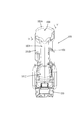
- FIG. 1 is an external view showing an overall configuration of an electro-pneumatic nailer.
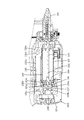
- FIG. It is A arrow directional view of FIG. It is sectional drawing which shows the whole structure of the internal mechanism of a nailing machine.
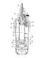
- FIG. 4 is a sectional view taken along line IV-IV in FIG. 3.
- FIG. 5 is a sectional view taken along line VV in FIG. 2.
- FIG. 4 is a cross-sectional view taken along the line VI-VI in FIG. 3 and shows a state where the valve is closed.
- FIG. 6 shows a nailing state in which the valve is opened and the driving piston is moved forward.
- FIG. 6 shows a state in which the open state of the valve is maintained, and the driving piston is returned to the vicinity of the rear initial position.
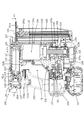
- It is a block diagram which shows the control system of a nailing machine.
- the nailing machine 100 is configured mainly by a main body housing 101 and a magazine 105 when viewed generally.
- the main body housing 101 constitutes a tool main body and forms an outline of the nailing machine 100.
- the magazine 105 is loaded with nails (not shown) that are driven into the workpiece.
- the main body housing 101 is formed by joining together a pair of substantially symmetrical housings.
- the main body housing 101 includes a handle portion 103, a driving mechanism housing portion 101A, a compression device housing portion 101B, and a motor housing portion 101C.
- the handle portion 103, the driving mechanism housing portion 101A, the compression device housing portion 101B, and the motor housing portion 101C are arranged so as to form a substantially rectangular shape.
- the handle portion 103 is a long member extending at a predetermined length.
- One end side of the handle portion 103 is connected to one end side of the driving mechanism housing portion 101A, and the other end side of the handle portion 103 is connected to one end side of the motor housing portion 101C.
- the compression device housing portion 101 ⁇ / b> B is disposed so as to extend substantially parallel to the handle portion 103.
- One end side of the compression device accommodating portion 101B is connected to the other end side of the driving mechanism accommodating portion 101A, and the other end side of the compression device accommodating portion 101B is connected to the other end side of the motor accommodating portion 101C.
- the nailing machine 100 forms a space S surrounded by the handle portion 103, the driving mechanism housing portion 101A, the compression device housing portion 101B, and the motor housing portion 101C.
- a driver guide 141 and an LED 107 are arranged at the tip (right end in FIG. 1).
- the right direction is the nail launch direction.
- the front end side (right side in FIG. 1) of the nailing machine 100 is referred to as the front side
- the opposite side (left side in FIG. 1) is referred to as the rear side.
- the connection side (upper side in FIG. 1) of the handle portion 103 with the driving mechanism housing portion 101A is the upper side
- the connection side (lower side in FIG. 1) of the handle portion 103 with the motor storage portion 101C is down. Called the side.
- the driving mechanism accommodating portion 101A accommodates the nail driving mechanism 120.
- the nail driving mechanism 120 is mainly composed of a driving cylinder 121 and a driving piston 123.
- the driving cylinder 121 accommodates the driving piston 123 so as to be slidable in the front-rear direction (long axis direction).
- the driving piston 123 has a piston main body 124 and a driver 125.
- the driver 125 is a long member.
- the driver 125 is provided integrally with the piston main body 124 and is disposed so as to extend forward.
- the piston main body 124 and the driver 125 are configured to be driven by compressed air supplied to the cylinder chamber 121a so as to be movable in the major axis direction of the cylinder 121. As a result, the driver 125 moves forward in the driving path 141a of the driver guide 141 to drive out the nail.
- the driving cylinder chamber 121 a is formed as a space surrounded by the inner wall surface of the driving cylinder 121 and the rear surface of the piston main body 124.
- the driver guide 141 is disposed at the tip of the driving cylinder 121 and includes a driving passage 141a having a nail injection port at the tip.
- the magazine 105 is disposed on the front end side of the main body housing 101, that is, in front of the compression device housing portion 101 ⁇ / b> B.
- the magazine 105 accommodates nails that are driving tools.
- the magazine 105 is connected to the driver guide 141, and supplies nails to the driving path 141a.
- the magazine 105 is provided with a pusher plate 105a for pushing the nail in the supply direction (upward in FIG. 3). By this pusher plate 105a, the nails are supplied to the driving path 141a of the driver guide 141 one by one from the direction intersecting the driving direction.
- the compression device accommodating portion 101 ⁇ / b> B accommodates the compression device 130.
- the compression device 130 is mainly configured by a compression cylinder 131, a compression piston 133, and a crank mechanism 115.
- the compression piston 133 is arranged to be slidable in the vertical direction within the compression cylinder 131.
- the compression cylinder 131 and the compression piston 133 are implementation configuration examples corresponding to “cylinder” and “piston” in the present invention, respectively.
- the compression cylinder 131 is disposed along the magazine 105, and the upper end side of the compression cylinder 131 is connected to the front end portion of the driving cylinder 121.
- the compression piston 133 is arranged so as to slide up and down along the magazine 105.
- the operation direction of the compression piston 133 is substantially orthogonal to the operation direction of the driving piston 123.
- the volume of the compression chamber 131a that is the internal space of the compression cylinder 131 changes. That is, the compression piston 133 moves upward to reduce the volume of the compression chamber 131a, thereby compressing the air in the compression chamber 131a.
- the compression chamber 131 a is formed on the upper side close to the driving cylinder 121.
- the compression cylinder 131 includes an atmospheric release valve (not shown), and is configured to be able to release the compression chamber 131a to the atmosphere. The air release valve is normally kept closed.
- the motor housing portion 101 ⁇ / b> C houses the electric motor 111.
- the electric motor 111 is arranged so that the rotation axis of the motor shaft is substantially parallel to the long axis of the driving cylinder 121. Therefore, the rotation axis of the electric motor 111 is orthogonal to the operation direction of the compression piston 133.
- a battery mounting area is formed on the lower side of the motor housing 101C, and a rechargeable battery pack 110 that supplies power to the electric motor 111 is detachably mounted.
- This battery pack 110 is an implementation configuration example corresponding to the “battery” in the present invention.
- the rotation of the electric motor 111 is transmitted to the crank mechanism 115 after being decelerated by the planetary gear type reduction mechanism 113.
- the rotation of the electric motor 111 is converted into a linear motion by the crank mechanism 115 and transmitted to the compression piston 133.
- the speed reduction mechanism 113 and the crank mechanism 115 are accommodated in the inner housing 102.
- the inner housing 102 is disposed between the compression device housing portion 101B and the motor housing portion 101C.
- This electric motor 111 is an implementation configuration example corresponding to the “motor” in the present invention.
- the crank mechanism 115 is mainly composed of a crankshaft 115a, an eccentric pin 115b, and a connecting rod 115c.
- the crankshaft 115a is connected to a planetary gear type reduction mechanism 113. That is, the crankshaft 115 a is rotationally driven by the rotation of the electric motor 111 decelerated by the reduction mechanism 113.
- the eccentric pin 115b is provided at a position eccentric from the rotation center of the crankshaft 115a.
- One end of the connecting rod 115c is connected to the eccentric pin 115b so as to be relatively rotatable, and the other end is connected to the compression piston 133 so as to be relatively rotatable.
- the crank mechanism 115 is disposed below the compression cylinder 131.
- a reciprocating compression device mainly including the compression cylinder 131, the compression piston 133, and the crank mechanism 115 is configured as the compression device 130.
- the handle portion 103 is provided with a trigger 103a and a trigger switch 103b.
- the trigger switch 103b is turned on.
- the trigger switch 103b is turned off by releasing the pulling operation of the trigger 103a. That is, the trigger 103a is configured to be movable between a front position (right side in FIG. 3) not operated by the user and a rear position (left side in FIG. 3) operated by the user.
- the trigger switch 103b is turned off.
- the trigger switch 103b is turned on.
- the trigger 103a and the trigger switch 103b are implementation configuration examples corresponding to the “second movable member” and the “second switch” in the present invention, respectively. Further, the front side position and the rear side position where the trigger 103a is located are implementation examples corresponding to the “third position” and the “fourth position” in the present invention, respectively.
- the driver guide 141 as a contact arm is disposed in the front end region of the main body housing 101 so as to be movable in the front-rear direction of the nailing machine 100. As shown in FIG. 6, the driver guide 141 is urged forward by an urging spring 142. When the driver guide 141 is positioned forward, the contact arm switch 143 is turned off. On the other hand, when the driver guide 141 is moved to the main body housing 101 side, the contact arm switch 143 is turned on. That is, the driver guide 141 is configured to be movable between a front position and a rear position on the main body housing 101 side.
- the driver guide 141 and the contact arm switch 143 are implementation configuration examples corresponding to the “first movable member” and the “first switch” in the present invention, respectively. Further, the front position and the rear position where the driver guide 141 is located are implementation examples corresponding to the “first position” and the “second position” in the present invention, respectively.
- a control device 109 is arranged below the crank mechanism 115.
- the electric motor 111 is configured to be controlled by the control device 109 according to the operation of the trigger 103 a provided in the handle portion 103 and the driver guide 141 provided in the distal end region of the main body housing 101. That is, the electric motor 111 is energized when both the trigger switch 103b and the contact arm switch 143 are switched on, and is stopped when either one is switched to the off state.
- This control device 109 is an implementation configuration example corresponding to the “controller” in the present invention.
- the nail driver 100 includes an air passage 135 and a valve chamber 137 a that connect the compression chamber 131 a of the compression cylinder 131 and the cylinder chamber 121 a of the driving cylinder 121.
- the air passage 135 mainly includes a communication port 135a, a communication port 135b, a communication passage 135c, an annular groove 121c, and a valve chamber 137a.
- the communication port 135 a is formed in the cylinder head 131 b of the compression cylinder 131.
- the communication port 135a communicates with the compression chamber 131a.
- the communication port 135 b is formed in the cylinder head 121 b of the driving cylinder 121.
- the communication port 135b communicates with the valve chamber 137a.
- the communication path 135c connects the communication port 135a and the communication port 135b.
- the communication path 135 c extends linearly in the front-rear direction along the driving cylinder 121.
- the communication port 135b communicates with an annular groove 121c formed in the peripheral surface of the valve chamber 137a.
- the annular groove 121c communicates with the valve chamber 137a.
- the valve chamber 137a communicates with the cylinder chamber 121a.
- the communication port 135b communicates with the cylinder chamber 121a via the annular groove 121c and the valve chamber 137a.
- An electromagnetic valve 137 that opens and closes the air passage 135 is accommodated in the valve chamber 137a.
- the electromagnetic valve 137 is a columnar member having substantially the same diameter as the piston main body 124 of the driving piston 123.
- the electromagnetic valve 137 is disposed so as to be movable in the front-rear direction within the valve chamber 137a.
- An electromagnet 138 is disposed behind the electromagnetic valve 137. Then, by switching energization to the electromagnet 138, the electromagnetic valve 137 moves in the front-rear direction.
- two O-rings 139a and 139b are arranged at a predetermined interval in the front-rear direction. The electromagnetic valve 137 moves rearward to open the annular groove 121c, and moves forward to close the annular groove 121c.
- the front O-ring 139a contacts the inner wall surface of the valve chamber 137a in front of the annular groove 121c, thereby blocking communication between the annular groove 121c and the cylinder chamber 121a.
- the annular groove 121c communicates with the cylinder chamber 121a.
- the rear O-ring 139b prevents the compressed air from leaking outside from the communication port 135b. That is, the O-ring 139b is not involved in opening / closing the annular groove 121c.
- the electromagnetic valve 137 that opens and closes the air passage 135 is provided in the air passage 135 on the connection side of the driving cylinder 121 with the cylinder chamber 121a.
- the electromagnetic valve 137 is always disposed in front of the annular groove 121 c closed by the electromagnet 138.
- the stopper 136 is disposed in front of the electromagnetic valve 137 and restricts the movement of the electromagnetic valve 137 forward.
- the stopper 136 is formed by a flange-like member protruding in the radial direction in the cylinder chamber 121a. Further, the stopper 136 defines the rear end position of the driving piston 123 that moves rearward.
- the nail driver 100 includes a main switch 200 connected to a control device 109.
- the main switch 200 When the main switch 200 is on, current is supplied from the battery pack 110 to the electric motor 111 via the control device 109.
- the main switch 200 when the main switch 200 is in the off state, the current supply from the battery pack 110 is interrupted. That is, the main switch 200 is provided as a main power switch.
- the main switch 200 is an implementation configuration example corresponding to the “switch” in the present invention.
- the nailing machine 100 has the driving piston 123 positioned at the rearmost position (the leftmost position in FIG. 3) and the compression piston 133 at the maximum position with the main switch 200 switched to the on state.
- the state located at the lower end position (bottom dead center) is determined as the initial position. That is, the initial state is when the crank angle is 0 degrees (bottom dead center).
- the nail driver 100 includes a magnetic sensor 150.
- the magnetic sensor 150 is mainly composed of a magnet 151 and a hall element 152.
- the magnet 150 is provided on the crankshaft 115a.
- the Hall element 152 is provided at a position facing the magnet 151 of the compression device housing portion 101B.
- the hall element 152 is electrically connected to the battery pack 110 via the control device 109.
- the Hall element 152 detects the position of the crankshaft 115a, and the control device 109 defines the state where the compression piston 133 is located at the bottom dead center as the initial state.
- the driver guide 141 is pressed against the workpiece by an operation for driving the nail from the initial state, the contact arm switch 143 (see FIG. 6) is turned on, and the trigger 103a is turned on.
- the trigger switch 103b is switched to the on state by the pulling operation, the electric motor 111 is driven to energize.
- the crank mechanism 115 is driven via the speed reduction mechanism 113, and the compression piston 133 moves upward.
- the electromagnetic valve 137 closes the air passage 135, the air in the compression chamber 131a is compressed by the movement of the compression piston 133.
- the control device 109 controls the electromagnet 138 and moves the electromagnetic valve 137 backward.
- the electromagnetic valve 137 is opened.
- the annular groove 121c communicates with the cylinder chamber 121a, and the compressed air in the compression chamber 131a is supplied into the cylinder chamber 121a through the air passage 135.
- the driving piston 123 is moved forward by the action of the air spring by the compressed air, as shown in FIG.
- the driver 125 of the driving piston 123 moved forward hits the nail waiting in the driving passage 141a (see FIG. 3). Thereby, a hammering operation for punching one nail is performed.
- the compression piston 133 moves toward the bottom dead center. At that time, the volume of the compression chamber 131a is increased, and the air in the compression chamber 131a becomes a negative pressure lower than the atmospheric pressure.
- the negative pressure generated in the compression chamber 131a is driven through the air passage 135 and the cylinder chamber 121a and acts on the piston 123. Thereby, as shown in FIG. 8, the driving piston 123 is sucked and moved rearward.
- the driving piston 123 is in contact with the stopper 136 and is located at the initial position.
- the control device 109 controls the electromagnet 138 and moves the electromagnetic valve 137 forward.
- the air passage 135 is closed.
- the compression piston 133 returns to the initial position, the supply of current to the electric motor 111 is cut off and the electric motor 111 is stopped. In this way, one cycle of the launching operation is completed.
- the LED 107 irradiates the tip region of the driver guide 141.
- the contact arm switch 143 that has been in the off state is turned on again to perform a further punching operation. It is configured as follows. That is, by repeatedly pressing the driver guide 141 against the workpiece and releasing the pressing while operating the trigger 103a, the number of nails corresponding to the number of times of pressing is driven out. As a result, it is possible to perform a continuous driving operation for driving nails continuously. It should be noted that after the nail is driven, even if the trigger 103a is operated to switch the on / off state of the trigger switch 103b while the contact arm switch 143 is maintained in the ON state, the driving operation is not performed. It is configured.
- the nailing machine 100 described above is configured such that a nail is driven when both the trigger switch 103b and the contact arm switch 143 are turned on.
- the trigger switch 103b and the contact arm switch 143 function as a safety device that prevents the nail from being unintentionally driven out due to a user's erroneous operation or the like. Therefore, it is necessary that the trigger switch 103b and the contact arm switch 143 operate normally. Therefore, in the present embodiment, it is detected whether or not the trigger switch 103b and the contact arm switch 143 that are activated based on the user's operation in the launching operation are operating normally. If any one of the switches is not operating normally, the control device 109 restricts the nail launch. In other words, the nail is prevented from being unintentionally driven out when the switch is not operating normally.
- the trigger switch 103b operates normally when the trigger 103a is positioned on the front side that is not operated by the user and is on when the trigger 103a is positioned on the rear side that is operated by the user. Is in a normal state. Therefore, when the trigger switch 103b is in the on state even though the trigger 103a is located on the front side not operated by the user, the trigger switch 103b is not operating normally. That is, the trigger switch 103b is in an abnormal state.
- the contact arm switch 143 is in an off state when the driver guide 141 is positioned forward, and when the driver guide 141 is pressed against the workpiece by a user operation during the launching operation and positioned rearward.
- the case where it is in the ON state is a state in which it is operating normally (normal state). Accordingly, when the contact arm switch 143 is in the on state even though the driver guide 141 is positioned forward because the driver guide 141 is not pressed against the workpiece, the contact arm switch 143 is not operating normally. That is, the contact arm switch 143 is in an abnormal state.
- the control device 109 is configured to detect whether or not the trigger switch 103b and the contact arm switch 143 are operating normally at a predetermined timing. That is, when the trigger 103a is positioned on the front side not being operated by the user, when the trigger switch 103b is on, or when the driver guide 141 is positioned on the front side not pressed against the workpiece, the contact is made.
- the control device 109 determines that any switch or an element that operates the switch has a problem. Then, the control device 109 regulates subsequent nail launching. That is, the control device 109 regulates the supply of current to the electric motor 111.
- the predetermined timing is defined as when the user wears the battery pack 110 and / or when the user switches the main switch 200 to the ON state. That is, when the battery pack 110 is mounted and when the main switch 200 is switched to the on state, the time is before the user performs a launching operation using the nail driver 100. At such time, the user does not normally operate the trigger 103a or press the driver guide 141 against the workpiece. In other words, the trigger 103a is positioned on the front side without being operated, and the driver guide 141 is positioned on the front side without being pressed against the workpiece. Therefore, when the trigger switch 103b and the contact arm switch 143 are in the normal state, both switches are in the off state.
- the control device 109 restricts the subsequent driving of the nail. As a result, it is possible to prevent the nail from being unintentionally driven out.
- the trigger switch 103b is maintained in the on state.
- the control device 109 determines that it is not the continuous launching operation. That is, the user's operation is determined as an erroneous operation. Therefore, the control device 109 cuts off the supply of current to the electric motor 111 and restricts the nail launch. In this case, when the trigger switch 103b is switched to the OFF state, the control device 109 cancels the restriction on nail launching. For example, 5 seconds is set as the predetermined time.
- the control device 109 controls the LEDs 107 and 108 to be lit when the nail driving is restricted. Thereby, the drive of the electric motor 111 is stopped, and it is notified that the launch of the nail is regulated. Note that the control device 109 may not only light the LEDs 107 and 108 but also blink them. The control device 109 may be configured to change the color of light emitted by the LEDs 107 and 108. Further, only one of the LEDs 107 and 108 may be lit or blinked.
- the nail launching is restricted. This prevents the nail from being unintentionally driven out in the state where the trigger switch 103b or the contact arm switch 143 is defective.
- the trigger switch 103b, the contact arm switch 143, the trigger 103a that operates the trigger switch 103b, or the driver guide 143 that operates the contact arm switch 141 has a defect. It is detected.
- control is performed based on the on / off state of the trigger switch 103b or the contact arm switch 143 when the battery pack 110 is mounted or when the main switch 200 is switched to the on state.
- Device 109 regulates nail launch. Therefore, it is possible to restrict nail launching without detecting the position of the trigger 103a that operates the trigger switch 103b or the driver guide 143 that operates the contact arm switch 143.
- the continuous launching operation when the user inadvertently continues the operation of the trigger 103a for a long time, by restricting subsequent nail launching, the user's carelessness or erroneous operation is caused. Nailing is prevented.
- the LEDs 107 and 108 can notify that nail launching is restricted. That is, the user can grasp that the malfunction of the nailing machine 100 is caused by the LEDs 107 and 108.
- the control device 109 when the user installs the battery pack 110 and / or when the user switches the main switch 200 to the on state, the control device 109 operates normally with the trigger switch 103b and the contact arm switch 143. Although it was configured to detect whether or not, the present invention is not limited to this.
- the control device 109 may be configured to always detect whether or not the trigger switch 103b and the contact arm switch 143 are operating normally. That is, it has sensors that detect the positions of the trigger 103a and the driver guide 141, respectively, and based on the relationship between the positions of the trigger 103a and the driver guide 141 and the on / off states of the trigger switch 103b and the contact arm switch 143. The control device 109 may be configured to detect whether the trigger switch 103b and the contact arm switch 143 are operating normally.
- the trigger 103a or the driver guide 141 may be used depending on the state in which the nail driver 100 is placed. May have been operated.
- the trigger 103a or the driver guide 141 is defective and the trigger 103a or the driver guide 141 is not located at a position where it is not operated. Therefore, when the user installs the battery pack 110 and / or when the user switches the main switch 200 to the on state, either the trigger switch 103b or the contact arm switch 143 is used regardless of the state of the nail driver 100.
- the control device 109 may be configured to restrict the driving of the nail. That is, at the predetermined timing, regardless of the position of the trigger 103a and / or the position of the driver guide 141, the case where either the trigger switch 103b or the contact arm switch 143 is on is regarded as an abnormal state. May be. In the case of an abnormal state, the control device 109 regulates the nail launch. In this case, when the trigger switch 103b and the contact arm switch 143 are turned off, the control device 109 is configured to allow subsequent nail launch.
- the LEDs 107 and 108 are provided as notification means. However, only one LED may be provided. Further, a buzzer for generating sound or an actuator for generating vibration may be provided as the notification means.
- the battery pack 110 is configured to be detachable.
- the battery pack 110 may be fixed to the nailing machine 100 as long as it is configured to be rechargeable.
- the driving tool can be configured as follows.
- a first movable member that contacts the workpiece and is moved from the first position to the second position on the basis of a user operation when driving the driving tool;
- a first switch configured to be in an off state when the first movable member is located at the first position and to be turned on when the first movable member is located at the second position;
- a second movable member that is operated by a user when driving the driving tool and is moved from a third position to a fourth position;
- a second switch configured to be in an off state when the second movable member is located at the third position and to be turned on when the second movable member is located at the fourth position;
- Have A battery for supplying current to the motor is configured to be mountable, When the first switch and the second switch are both turned
- a driving tool characterized by (Aspect 2) A driving tool for driving a driving tool from an injection port, A cylinder, A piston slidable in the cylinder; A motor for driving the piston; A controller for controlling the motor; A first movable member that contacts the workpiece and is moved from the first position to the second position on the basis of a user operation when driving the driving tool; A first switch configured to be in an off state when the first movable member is located at the first position and to be turned on when the first movable member is located at the second position; , A second movable member that is operated by a user when driving the driving tool and is moved from a third position to a fourth position; A second switch configured to be in an off state when the second movable member is located at the third position and to be turned on when the second movable member is located at the fourth position; Have A battery for supplying current to the motor is configured to be mountable, When the first switch and the second switch are both turned on, the controller drives the motor to cause an air pressure fluctuation in the cylinder,
- a driving tool characterized by (Aspect 4) A driving tool according to any one of claims 1 to 8 or aspects 1 to 3,
- the first movable member is a contact arm that moves in contact with a workpiece based on a user operation,
- the driving tool, wherein the second movable member is a trigger that is directly operated by a user's finger.
- each component of this embodiment shows an example of the form for implementing this invention, and this invention is not limited to the structure of this embodiment.
- the nailing machine 100 is an example of a configuration corresponding to the “driving tool” of the present invention.
- the control device 109 is an example of a configuration corresponding to the “controller” of the present invention.
- the battery pack 110 is an example of a configuration corresponding to the “battery” of the present invention.
- the electric motor 111 is an example of a configuration corresponding to the “motor” of the present invention.
- the compression piston 133 is an example of a configuration corresponding to the “piston” of the present invention.
- the trigger 103a is an example of a configuration corresponding to the “second movable member” of the present invention.
- the trigger switch 103b is an example of a configuration corresponding to the “second switch” of the present invention.
- the driver guide 141 is an example of a configuration corresponding to the “first movable member” of the present invention.
- the contact arm switch 143 is an example of a configuration corresponding to the “first switch” of the present invention.
- the main switch 200 is an example of a configuration corresponding to the “switch” of the present invention.
- LED107 is an example of the structure corresponding to the "notification means” of this invention.
- the LED 108 is an example of a configuration corresponding to the “notification unit” of the present invention.
Landscapes
- Engineering & Computer Science (AREA)
- Mechanical Engineering (AREA)
- Physics & Mathematics (AREA)
- Fluid Mechanics (AREA)
- Portable Nailing Machines And Staplers (AREA)
Abstract
Description
本発明の他の特質、作用および効果については、本明細書、特許請求の範囲、添付図面を参照することで直ちに理解可能である。
代表的な実施形態につき、図1~図9を参照して説明する。本実施形態は、打ち込み工具の一例として電気-空圧式釘打機を用いて説明する。図1及び図2に示すように、釘打機100は、概括的に見て、本体ハウジング101と、マガジン105を主体として構成される。本体ハウジング101は、工具本体を構成しており、釘打機100の外郭を形成している。マガジン105には、被加工材に打ち込まれる釘(図示省略)が装填されている。本体ハウジング101は、ほぼ対称形の1対のハウジングを合わせて結合して形成されている。当該本体ハウジング101は、ハンドル部103、打ち込み機構収容部101A、圧縮装置収容部101B、モータ収容部101Cを備えている。
(態様1)
打ち込み具を射出口から打ち出す打ち込み工具であって、
シリンダと、
前記シリンダ内を摺動可能なピストンと、
前記ピストンを駆動するモータと、
前記モータを制御するコントローラと、
前記打ち込み具を打ち出す際のユーザの操作に基づいて、被加工材に当接して第1の位置から第2の位置に移動される第1可動部材と、
前記第1可動部材が前記第1の位置に位置する場合にオフ状態であり、前記第1可動部材が前記第2の位置に位置する場合にオン状態となるように構成された第1スイッチと、
前記打ち込み具を打ち出す際にユーザに操作されて、第3の位置から第4の位置に移動される第2可動部材と、
前記第2可動部材が前記第3の位置に位置する場合にオフ状態であり、前記第2可動部材が前記第4の位置に位置する場合にオン状態となるように構成された第2スイッチと、を有し、
前記モータに電流を供給するためのバッテリが装着可能に構成されており、
前記コントローラは、前記第1スイッチと前記第2スイッチが共にオン状態となった場合に、前記モータを駆動することで前記シリンダ内に空気の圧力変動を生じさせて、当該圧力変動により前記打ち込み具を打ち出すように構成されており、
前記バッテリは、当該打ち込み工具に対して着脱可能に構成されており、
前記バッテリを装着したときに、前記第1スイッチと前記第2スイッチの少なくとも一方のスイッチがオン状態であることを検出した場合に、前記コントローラは、前記打ち込み具の打ち出しを規制するように構成されていることを特徴とする打ち込み工具。
(態様2)
打ち込み具を射出口から打ち出す打ち込み工具であって、
シリンダと、
前記シリンダ内を摺動可能なピストンと、
前記ピストンを駆動するモータと、
前記モータを制御するコントローラと、
前記打ち込み具を打ち出す際のユーザの操作に基づいて、被加工材に当接して第1の位置から第2の位置に移動される第1可動部材と、
前記第1可動部材が前記第1の位置に位置する場合にオフ状態であり、前記第1可動部材が前記第2の位置に位置する場合にオン状態となるように構成された第1スイッチと、
前記打ち込み具を打ち出す際にユーザに操作されて、第3の位置から第4の位置に移動される第2可動部材と、
前記第2可動部材が前記第3の位置に位置する場合にオフ状態であり、前記第2可動部材が前記第4の位置に位置する場合にオン状態となるように構成された第2スイッチと、を有し、
前記モータに電流を供給するためのバッテリが装着可能に構成されており、
前記コントローラは、前記第1スイッチと前記第2スイッチが共にオン状態となった場合に、前記モータを駆動することで前記シリンダ内に空気の圧力変動を生じさせて、当該圧力変動により前記打ち込み具を打ち出すように構成されており、
前記バッテリから前記コントローラへの電流供給を許容する電流供給許容状態と、当該電流供給を遮断する電流供給遮断状態を切り替える切替スイッチを有しており、
前記切替スイッチが前記電流供給遮断状態から前記電流供給許容状態に切り替えられたときに、前記第1スイッチと前記第2スイッチの少なくとも一方のスイッチがオン状態であることを検出した場合に、前記コントローラは、前記打ち込み具の打ち出しを規制するように構成されていることを特徴とする打ち込み工具。
(態様3)
態様1または2に記載の打ち込み工具であって、
前記第1スイッチがオフ状態であることを検出した場合、且つ前記第2スイッチがオフ状態であることを検出した場合に、前記コントローラは、その後の前記打ち込み具の打ち出しを許容するように構成されていることを特徴とする打ち込み工具。
(態様4)
請求項1~8または態様1~3のいずれか1項に記載の打ち込み工具であって、
前記第1可動部材は、ユーザの操作に基づいて、被加工材に当接して移動されるコンタクトアームであり、
前記第2可動部材は、ユーザの指で直接操作されるトリガであることを特徴とする打ち込み工具。
本実施形態の各構成要素と本発明の各構成要素の対応関係を以下の通りである。なお、本実施形態は、本発明を実施するための形態の一例を示すものであり、本発明は、本実施形態の構成に限定されるものではない。
釘打機100は、本発明の「打ち込み工具」に対応する構成の一例である。
制御装置109は、本発明の「コントローラ」に対応する構成の一例である。
バッテリパック110は、本発明の「バッテリ」に対応する構成の一例である。
電動モータ111は、本発明の「モータ」に対応する構成の一例である。
圧縮ピストン133は、本発明の「ピストン」に対応する構成の一例である。
トリガ103aは、本発明の「第2可動部材」に対応する構成の一例である。
トリガスイッチ103bは、本発明の「第2スイッチ」に対応する構成の一例である。
ドライバガイド141は、本発明の「第1可動部材」に対応する構成の一例である。
コンタクトアームスイッチ143は、本発明の「第1スイッチ」に対応する構成の一例である。
メインスイッチ200は、本発明の「切替スイッチ」に対応する構成の一例である。
LED107は、本発明の「報知手段」に対応する構成の一例である。
LED108は、本発明の「報知手段」に対応する構成の一例である。
101 本体ハウジング
101A 打ち込み機構収容部
101B 圧縮装置収容部
101C モータ収容部
102 内側ハウジング
103 ハンドル部
103a トリガ
103b トリガスイッチ
105 マガジン
105a プッシャプレート
107 LED
108 LED
109 制御装置
110 バッテリパック
111 電動モータ
113 減速機構
115 クランク機構
115a クランク軸
115b 偏心ピン
115c 連接ロッド
120 釘打ち込み機構
121 打ち込みシリンダ
121a シリンダ室
121b シリンダヘッド
121c 環状溝
123 打ち込みピストン
124 ピストン本体部
125 ドライバ
130 圧縮装置
131 圧縮シリンダ
131a 圧縮室
131b シリンダヘッド
133 圧縮ピストン
135 空気通路
135a 連通ポート
135b 連通ポート
135c 連通路
136 ストッパ
137 電磁バルブ
137a バルブ室
138 電磁石
139a Oリング
139b Oリング
141 ドライバガイド
141a 打ち込み通路
142 付勢ばね
143 コンタクトアームスイッチ
150 磁気センサ
151 磁石
152 ホール素子
160 電圧センサ
161 電流センサ
200 メインスイッチ
Claims (9)
- 打ち込み具を射出口から打ち出す打ち込み工具であって、
シリンダと、
前記シリンダ内を摺動可能なピストンと、
前記ピストンを駆動するモータと、
前記モータを制御するコントローラと、
前記打ち込み具を打ち出す際のユーザの操作に基づいて、被加工材に当接して第1の位置から第2の位置に移動される第1可動部材と、
前記第1可動部材が前記第1の位置に位置する場合にオフ状態であり、前記第1可動部材が前記第2の位置に位置する場合にオン状態となるように構成された第1スイッチと、
前記打ち込み具を打ち出す際にユーザに操作されて、第3の位置から第4の位置に移動される第2可動部材と、
前記第2可動部材が前記第3の位置に位置する場合にオフ状態であり、前記第2可動部材が前記第4の位置に位置する場合にオン状態となるように構成された第2スイッチと、を有し、
前記モータに電流を供給するためのバッテリが着脱可能に装着されるように構成されており、
前記コントローラは、前記第1スイッチと前記第2スイッチが共にオン状態となった場合に、前記モータを駆動することで前記シリンダ内に空気の圧力変動を生じさせて、当該圧力変動により前記打ち込み具を打ち出すように構成されており、
前記第1可動部材が前記第1の位置に位置するときに前記第1スイッチがオン状態であることを検出した場合、
前記第2可動部材が前記第3の位置に位置するときに前記第2スイッチがオン状態であることを検出した場合、
前記第1可動部材が前記第2の位置に位置するときに、前記第1スイッチが所定時間継続してオン状態であることを検出した場合、
前記第2可動部材が前記第4の位置に位置するときに、前記第2スイッチが所定時間継続してオン状態であることを検出した場合、のうちの少なくとも1つの場合において、
前記コントローラは、前記打ち込み具の打ち出しを規制するように構成されていることを特徴とする打ち込み工具。 - 請求項1に記載の打ち込み工具であって、
前記第1可動部材が前記第1の位置に位置するときに前記第1スイッチがオン状態であることを検出した場合、または
前記第2可動部材が前記第3の位置に位置するときに前記第2スイッチがオン状態であることを検出した場合に、
前記コントローラは、前記打ち込み具の打ち出しを規制するように構成されていることを特徴とする打ち込み工具。 - 請求項2に記載の打ち込み工具であって、
前記バッテリを装着したときに、前記第1スイッチと前記第2スイッチの少なくとも一方のスイッチがオン状態であることを検出した場合に、前記コントローラは、前記打ち込み具の打ち出しを規制するように構成されていることを特徴とする打ち込み工具。 - 請求項2または3に記載の打ち込み工具であって、
前記バッテリから前記コントローラへの電流供給を許容する電流供給許容状態と、当該電流供給を遮断する電流供給遮断状態を切り替える切替スイッチを有しており、
前記切替スイッチが前記電流供給遮断状態から前記電流供給許容状態に切り替えられたときに、前記第1スイッチと前記第2スイッチの少なくとも一方のスイッチがオン状態であることを検出した場合に、前記コントローラは、前記打ち込み具の打ち出しを規制するように構成されていることを特徴とする打ち込み工具。 - 請求項2~4のいずれか1項に記載の打ち込み工具であって、
前記第1可動部材が前記第2の位置に位置するときに、前記第1スイッチが所定時間継続してオン状態であることを検出した場合、または、前記第2可動部材が前記第4の位置に位置するときに、前記第2スイッチが所定時間継続してオン状態であることを検出した場合に、前記コントローラは、前記打ち込み具の打ち出しを規制するように構成されていることを特徴とする打ち込み工具。 - 請求項1に記載の打ち込み工具であって、
前記第1可動部材が前記第2の位置に位置するときに、前記第1スイッチが所定時間継続してオン状態であることを検出した場合、または、
前記第2可動部材が前記第4の位置に位置するときに、前記第2スイッチが所定時間継続してオン状態であることを検出した場合に、
前記コントローラは、前記打ち込み具の打ち出しを規制するように構成されていることを特徴とする打ち込み工具。 - 請求項5または6に記載の打ち込み工具であって、
前記第1可動部材が前記第1の位置に位置して前記第1スイッチがオフ状態であることを検出した場合、且つ前記第2可動部材が前記第3の位置に位置して前記第2スイッチがオフ状態であることを検出した場合に、前記コントローラは、その後の前記打ち込み具の打ち出しを許容するように構成されていることを特徴とする打ち込み工具。 - 請求項1~7のいずれか1項に記載の打ち込み工具であって、
前記コントローラによって前記打ち込み具の打ち出しが規制されていることを報知する報知手段を有することを特徴とする打ち込み工具。 - 請求項1~8のいずれか1項に記載の打ち込み工具であって、
前記第1可動部材は、ユーザの操作に基づいて、被加工材に当接して移動されるコンタクトアームであり、
前記第2可動部材は、ユーザの指で直接操作されるトリガであることを特徴とする打ち込み工具。
Priority Applications (2)
| Application Number | Priority Date | Filing Date | Title |
|---|---|---|---|
| US14/440,143 US10272553B2 (en) | 2012-11-05 | 2013-11-01 | Driving tool |
| DE112013005280.6T DE112013005280T5 (de) | 2012-11-05 | 2013-11-01 | Eintreibwerkzeug |
Applications Claiming Priority (2)
| Application Number | Priority Date | Filing Date | Title |
|---|---|---|---|
| JP2012-243442 | 2012-11-05 | ||
| JP2012243442A JP2014091196A (ja) | 2012-11-05 | 2012-11-05 | 打ち込み工具 |
Publications (1)
| Publication Number | Publication Date |
|---|---|
| WO2014069648A1 true WO2014069648A1 (ja) | 2014-05-08 |
Family
ID=50627540
Family Applications (1)
| Application Number | Title | Priority Date | Filing Date |
|---|---|---|---|
| PCT/JP2013/079799 Ceased WO2014069648A1 (ja) | 2012-11-05 | 2013-11-01 | 打ち込み工具 |
Country Status (4)
| Country | Link |
|---|---|
| US (1) | US10272553B2 (ja) |
| JP (1) | JP2014091196A (ja) |
| DE (1) | DE112013005280T5 (ja) |
| WO (1) | WO2014069648A1 (ja) |
Cited By (5)
| Publication number | Priority date | Publication date | Assignee | Title |
|---|---|---|---|---|
| US9827659B2 (en) | 2012-04-09 | 2017-11-28 | Makita Corporation | Driver tool |
| US9844865B2 (en) | 2012-04-09 | 2017-12-19 | Makita Corporation | Driver tool |
| US9943952B2 (en) | 2013-12-11 | 2018-04-17 | Makita Corporation | Driving tool |
| US10131047B2 (en) | 2012-05-08 | 2018-11-20 | Makita Corporation | Driving tool |
| US10286534B2 (en) | 2014-04-16 | 2019-05-14 | Makita Corporation | Driving tool |
Families Citing this family (17)
| Publication number | Priority date | Publication date | Assignee | Title |
|---|---|---|---|---|
| JP2014091196A (ja) | 2012-11-05 | 2014-05-19 | Makita Corp | 打ち込み工具 |
| DE102013106657A1 (de) * | 2013-06-25 | 2015-01-08 | Illinois Tool Works Inc. | Eintreibwerkzeug zum Eintreiben von Befestigungsmitteln in ein Werkstück |
| DE102013106658A1 (de) * | 2013-06-25 | 2015-01-08 | Illinois Tool Works Inc. | Eintreibwerkzeug zum Eintreiben von Befestigungsmitteln in ein Werkstück |
| DE102014206076A1 (de) * | 2014-03-31 | 2015-10-01 | Robert Bosch Gmbh | Handwerkzeugmaschine, Verfahren zum Betreiben |
| JP6408944B2 (ja) * | 2015-03-24 | 2018-10-17 | 株式会社マキタ | 打ち込み工具 |
| JP6623662B2 (ja) * | 2015-10-09 | 2019-12-25 | マックス株式会社 | 打込機 |
| US11110577B2 (en) | 2017-11-16 | 2021-09-07 | Milwaukee Electric Tool Corporation | Pneumatic fastener driver |
| US11065749B2 (en) | 2018-03-26 | 2021-07-20 | Tti (Macao Commercial Offshore) Limited | Powered fastener driver |
| EP3809583B1 (en) * | 2018-06-15 | 2023-07-05 | Panasonic Intellectual Property Management Co., Ltd. | Cut-off circuit diagnostic device |
| US11130221B2 (en) | 2019-01-31 | 2021-09-28 | Milwaukee Electric Tool Corporation | Powered fastener driver |
| JP7523965B2 (ja) * | 2020-06-29 | 2024-07-29 | 株式会社マキタ | 打ち込み工具 |
| US11819989B2 (en) | 2020-07-07 | 2023-11-21 | Techtronic Cordless Gp | Powered fastener driver |
| JP7650448B2 (ja) * | 2021-05-10 | 2025-03-25 | マックス株式会社 | 打込工具 |
| CA3167425A1 (en) | 2021-07-16 | 2023-01-16 | Techtronic Cordless Gp | Powered fastener driver |
| CN217168397U (zh) | 2021-12-07 | 2022-08-12 | 南京腾亚精工科技股份有限公司 | 一种防尘紧固件击打工具 |
| EP4357082B1 (en) | 2022-06-01 | 2025-12-03 | Techtronic Cordless GP | Powered fastener driver |
| US12395046B2 (en) | 2022-07-22 | 2025-08-19 | Techtronic Cordless Gp | Firmware control providing a soft stop on compression drive nailer |
Citations (6)
| Publication number | Priority date | Publication date | Assignee | Title |
|---|---|---|---|---|
| JPH0666967U (ja) * | 1993-01-29 | 1994-09-20 | リョービ株式会社 | 打込み機の打込み動作様式切り換え装置 |
| JP2009090384A (ja) * | 2007-10-04 | 2009-04-30 | Makita Corp | 打ち込み工具 |
| JP2009172762A (ja) * | 2008-01-23 | 2009-08-06 | Hilti Ag | 燃焼力作動式ファスナ打込み装置 |
| JP2010005776A (ja) * | 2008-06-30 | 2010-01-14 | Hitachi Koki Co Ltd | 電動式打込機 |
| JP2010173044A (ja) * | 2009-01-30 | 2010-08-12 | Max Co Ltd | 工具 |
| JP2012148346A (ja) * | 2009-07-24 | 2012-08-09 | Makita Corp | 打込み工具 |
Family Cites Families (89)
| Publication number | Priority date | Publication date | Assignee | Title |
|---|---|---|---|---|
| US1071387A (en) | 1912-10-05 | 1913-08-26 | Hans Charles Behr | Percussive apparatus. |
| US1829609A (en) | 1929-05-06 | 1931-10-27 | Frank R Robinson | Pneumatic hammer |
| US3552274A (en) | 1968-05-27 | 1971-01-05 | Signode Corp | Pneumatic piston return system for impact tools |
| US3602103A (en) | 1969-07-31 | 1971-08-31 | Powers Wire Products Co Inc | Slide-latch valve for air-driven tools |
| US3638534A (en) | 1969-08-18 | 1972-02-01 | Fastener Corp | Fastener driving tool with improved pneumatic piston retaining means |
| JPS519938B2 (ja) | 1971-09-23 | 1976-03-31 | ||
| JPS519199B2 (ja) | 1972-04-03 | 1976-03-24 | ||
| US3824898A (en) | 1972-04-12 | 1974-07-23 | R Pauliukonis | Energy conserving directional valve-cylinder combination |
| CH584591A5 (ja) | 1974-05-20 | 1977-02-15 | Bosch Gmbh Robert | |
| US4344555A (en) | 1980-02-19 | 1982-08-17 | Signode Corporation | Self-cycling pneumatic fastener applying tool |
| JPS63229274A (ja) | 1987-03-14 | 1988-09-26 | 松下電工株式会社 | 釘打ち機 |
| JPH01115579A (ja) | 1987-10-27 | 1989-05-08 | Matsushita Electric Works Ltd | 打込機 |
| JPH0632308Y2 (ja) | 1988-11-17 | 1994-08-24 | マックス株式会社 | 空気圧式釘打機 |
| JPH0396751A (ja) | 1989-09-08 | 1991-04-22 | Shizuoka Tekkosho:Kk | 集合カム装置 |
| US5193730A (en) | 1991-06-14 | 1993-03-16 | Max Co., Ltd. | Pneumatic nailing machine |
| US6424799B1 (en) | 1993-07-06 | 2002-07-23 | Black & Decker Inc. | Electrical power tool having a motor control circuit for providing control over the torque output of the power tool |
| US5440215A (en) | 1993-07-06 | 1995-08-08 | Black & Decker Inc. | Electrical power tool having a motor control circuit for increasing the effective torque output of the power tool |
| JP2568736Y2 (ja) | 1993-12-06 | 1998-04-15 | マックス株式会社 | 可搬形電動ステープル打機 |
| JP3287172B2 (ja) | 1995-04-05 | 2002-05-27 | マックス株式会社 | 釘打ち機のトリガ装置 |
| US6499643B1 (en) | 1998-09-18 | 2002-12-31 | Stanley Fastenening Systems, L.P. | Drive channel for nailer |
| DE19962696C1 (de) | 1999-12-23 | 2001-06-07 | Hilti Ag | Brennkraftbetriebenes Arbeitsgerät mit Bremseinrichtung für seinen Kolben |
| US6755336B2 (en) | 2000-12-22 | 2004-06-29 | Kevin A. Harper | Return mechanism for a cyclic tool |
| US6604666B1 (en) | 2001-08-20 | 2003-08-12 | Tricord Solutions, Inc. | Portable electrical motor driven nail gun |
| US6705503B1 (en) | 2001-08-20 | 2004-03-16 | Tricord Solutions, Inc. | Electrical motor driven nail gun |
| JP4045418B2 (ja) | 2002-06-14 | 2008-02-13 | マックス株式会社 | 圧縮空気駆動衝撃工具の起動バルブ機構 |
| US20040232194A1 (en) | 2002-03-07 | 2004-11-25 | Pedicini Christopher S. | Enhanced electrical motor driven nail gun |
| JP4665432B2 (ja) | 2003-06-20 | 2011-04-06 | 日立工機株式会社 | 燃焼式動力工具 |
| DE602004015206D1 (de) | 2003-07-31 | 2008-09-04 | Makita Corp | Elektrowerkzeug |
| US20080217372A1 (en) | 2003-12-30 | 2008-09-11 | Poly Systems Pty Ltd | Fastener Driving Tool |
| US7285877B2 (en) | 2004-04-02 | 2007-10-23 | Black & Decker Inc. | Electronic fastening tool |
| US8408327B2 (en) | 2004-04-02 | 2013-04-02 | Black & Decker Inc. | Method for operating a power driver |
| US6971567B1 (en) | 2004-10-29 | 2005-12-06 | Black & Decker Inc. | Electronic control of a cordless fastening tool |
| US20080017689A1 (en) | 2006-05-31 | 2008-01-24 | David Simonelli | Fastener driving device |
| DE102005030340B3 (de) | 2005-06-29 | 2007-01-04 | Wacker Construction Equipment Ag | Schlagwerk mit elektrodynamischem Linearantrieb |
| DE102005000107B4 (de) * | 2005-08-25 | 2014-03-13 | Hilti Aktiengesellschaft | Pneumatisch betriebenes Setzgerät |
| US7511245B2 (en) | 2005-09-12 | 2009-03-31 | Nelson Stud Welding, Inc. | Stud welding apparatus with composite cable |
| DE102005000200B4 (de) | 2005-12-21 | 2014-07-03 | Hilti Aktiengesellschaft | Brennkraftbetriebenes Setzgerät |
| US7419079B2 (en) | 2006-02-03 | 2008-09-02 | Basso Industry Corp. | Pneumatic tool |
| JP4697669B2 (ja) | 2006-09-11 | 2011-06-08 | 日立工機株式会社 | 動力工具 |
| JP4692932B2 (ja) | 2006-09-14 | 2011-06-01 | 日立工機株式会社 | 電動式打込機 |
| JP4556188B2 (ja) * | 2006-09-14 | 2010-10-06 | 日立工機株式会社 | 電動式打込機 |
| US8875969B2 (en) * | 2007-02-09 | 2014-11-04 | Tricord Solutions, Inc. | Fastener driving apparatus |
| US7646157B2 (en) * | 2007-03-16 | 2010-01-12 | Black & Decker Inc. | Driving tool and method for controlling same |
| JP5133000B2 (ja) * | 2007-06-28 | 2013-01-30 | 株式会社マキタ | 電動打ち込み工具 |
| JP5073380B2 (ja) | 2007-06-28 | 2012-11-14 | 株式会社マキタ | 電動打ち込み工具 |
| US8011547B2 (en) * | 2007-10-05 | 2011-09-06 | Senco Brands, Inc. | Fastener driving tool using a gas spring |
| US20090108046A1 (en) | 2007-10-24 | 2009-04-30 | Chi-Sheng Huang | Trigger Switch Mechanism for Nail Gun |
| TWI440530B (zh) | 2008-02-06 | 2014-06-11 | Max Co Ltd | Hand tool, nail residual detection mechanism, nail residual detection method, and power saving method |
| JP5082899B2 (ja) | 2008-02-06 | 2012-11-28 | マックス株式会社 | 手持ち式工具における止具残量検出機構および止具残量検出方法 |
| US8534527B2 (en) | 2008-04-03 | 2013-09-17 | Black & Decker Inc. | Cordless framing nailer |
| CN101585182B (zh) | 2008-05-23 | 2011-08-31 | 台州市大江实业有限公司 | 一种打钉枪击发安全装置及安装有该装置的打钉枪 |
| JP5376216B2 (ja) | 2009-01-30 | 2013-12-25 | 日立工機株式会社 | 往復動工具 |
| US7793811B1 (en) | 2009-02-25 | 2010-09-14 | Tricord Solutions, Inc. | Fastener driving apparatus |
| US20100301091A1 (en) | 2009-06-01 | 2010-12-02 | Chia-Sheng Liang | Linkage Mechanism between Trigger Valve and Control Valve in Pneumatic Nail Guns |
| JP2011025363A (ja) | 2009-07-24 | 2011-02-10 | Makita Corp | 打込み工具 |
| JPWO2011010511A1 (ja) * | 2009-07-24 | 2012-12-27 | トリコード ソリューションズ,インコーポレイティド | 打込み工具 |
| JP2011025362A (ja) | 2009-07-24 | 2011-02-10 | Makita Corp | 打込み工具 |
| JP5424105B2 (ja) | 2009-09-09 | 2014-02-26 | 日立工機株式会社 | 電動式打込機 |
| EP2483037B1 (en) | 2009-09-30 | 2013-08-28 | Hitachi Koki Co., Ltd. | Fastener driving tool |
| US8523035B2 (en) * | 2009-11-11 | 2013-09-03 | Tricord Solutions, Inc. | Fastener driving apparatus |
| TW201117930A (en) | 2009-11-19 | 2011-06-01 | De Poan Pneumatic Corp | Driving device for resetting a nail hitting bar the a pneumatic nail gun |
| US8631986B2 (en) | 2009-12-04 | 2014-01-21 | Robert Bosch Gmbh | Fastener driver with an operating switch |
| US8640787B2 (en) | 2009-12-30 | 2014-02-04 | Daniel F. Rohrer | Portable post driving apparatus |
| JP5360692B2 (ja) | 2010-03-31 | 2013-12-04 | 日立工機株式会社 | 燃焼式打込機 |
| DE102010032335A1 (de) | 2010-07-20 | 2012-01-26 | C. & E. Fein Gmbh | Handwerkzeug |
| US9291056B2 (en) | 2010-08-30 | 2016-03-22 | Lawrence Livermore National Security, Llc | Harmonic uniflow engine |
| US8079504B1 (en) | 2010-11-04 | 2011-12-20 | Tricord Solutions, Inc. | Fastener driving apparatus |
| US9050712B2 (en) | 2011-01-20 | 2015-06-09 | Black & Decker Inc. | Driving tool with internal air compressor |
| US8800834B2 (en) | 2011-05-11 | 2014-08-12 | Tricord Solutions, Inc. | Fastener driving apparatus |
| TWI574796B (zh) | 2011-08-23 | 2017-03-21 | 日立工機股份有限公司 | 扣緊工具 |
| JP5800749B2 (ja) | 2012-04-09 | 2015-10-28 | 株式会社マキタ | 打込み工具 |
| JP5800748B2 (ja) | 2012-04-09 | 2015-10-28 | 株式会社マキタ | 打込み工具 |
| US9193055B2 (en) | 2012-04-13 | 2015-11-24 | Black & Decker Inc. | Electronic clutch for power tool |
| JP5758841B2 (ja) | 2012-05-08 | 2015-08-05 | 株式会社マキタ | 打ち込み工具 |
| US8733610B2 (en) | 2012-08-21 | 2014-05-27 | Tricord Solutions, Inc. | Fastener driving apparatus |
| JP2014083601A (ja) | 2012-10-19 | 2014-05-12 | Makita Corp | 打ち込み工具 |
| JP2014091196A (ja) | 2012-11-05 | 2014-05-19 | Makita Corp | 打ち込み工具 |
| JP6024446B2 (ja) | 2012-12-22 | 2016-11-16 | 日立工機株式会社 | インパクト工具 |
| JP6085488B2 (ja) | 2013-01-28 | 2017-02-22 | 株式会社マキタ | 電動工具 |
| JP6107385B2 (ja) | 2013-04-26 | 2017-04-05 | 日立工機株式会社 | 電動工具 |
| US8939341B2 (en) | 2013-06-20 | 2015-01-27 | Tricord Solutions, Inc. | Fastener driving apparatus |
| US9555530B2 (en) | 2013-06-20 | 2017-01-31 | Tricord Solutions, Inc. | Fastener driving apparatus |
| EP2826601A1 (de) | 2013-07-16 | 2015-01-21 | HILTI Aktiengesellschaft | Steuerungsverfahren und Handwerkzeugmaschine |
| JP6154242B2 (ja) | 2013-08-07 | 2017-06-28 | 株式会社マキタ | 電動機械器具 |
| JP6155175B2 (ja) | 2013-11-18 | 2017-06-28 | 株式会社マキタ | 電動工具の制動装置 |
| JP6100680B2 (ja) | 2013-12-11 | 2017-03-22 | 株式会社マキタ | 打ち込み工具 |
| CA2943806C (en) | 2014-03-27 | 2022-05-31 | Techtronic Power Tools Technology Limited | Powered fastener driver and operating method thereof |
| JP6284417B2 (ja) | 2014-04-16 | 2018-02-28 | 株式会社マキタ | 打ち込み工具 |
| US10427284B2 (en) | 2016-02-02 | 2019-10-01 | Makita Corporation | Fastener driving tool |
-
2012
- 2012-11-05 JP JP2012243442A patent/JP2014091196A/ja active Pending
-
2013
- 2013-11-01 DE DE112013005280.6T patent/DE112013005280T5/de active Pending
- 2013-11-01 US US14/440,143 patent/US10272553B2/en active Active
- 2013-11-01 WO PCT/JP2013/079799 patent/WO2014069648A1/ja not_active Ceased
Patent Citations (6)
| Publication number | Priority date | Publication date | Assignee | Title |
|---|---|---|---|---|
| JPH0666967U (ja) * | 1993-01-29 | 1994-09-20 | リョービ株式会社 | 打込み機の打込み動作様式切り換え装置 |
| JP2009090384A (ja) * | 2007-10-04 | 2009-04-30 | Makita Corp | 打ち込み工具 |
| JP2009172762A (ja) * | 2008-01-23 | 2009-08-06 | Hilti Ag | 燃焼力作動式ファスナ打込み装置 |
| JP2010005776A (ja) * | 2008-06-30 | 2010-01-14 | Hitachi Koki Co Ltd | 電動式打込機 |
| JP2010173044A (ja) * | 2009-01-30 | 2010-08-12 | Max Co Ltd | 工具 |
| JP2012148346A (ja) * | 2009-07-24 | 2012-08-09 | Makita Corp | 打込み工具 |
Cited By (5)
| Publication number | Priority date | Publication date | Assignee | Title |
|---|---|---|---|---|
| US9827659B2 (en) | 2012-04-09 | 2017-11-28 | Makita Corporation | Driver tool |
| US9844865B2 (en) | 2012-04-09 | 2017-12-19 | Makita Corporation | Driver tool |
| US10131047B2 (en) | 2012-05-08 | 2018-11-20 | Makita Corporation | Driving tool |
| US9943952B2 (en) | 2013-12-11 | 2018-04-17 | Makita Corporation | Driving tool |
| US10286534B2 (en) | 2014-04-16 | 2019-05-14 | Makita Corporation | Driving tool |
Also Published As
| Publication number | Publication date |
|---|---|
| DE112013005280T5 (de) | 2015-08-13 |
| US20150314432A1 (en) | 2015-11-05 |
| US10272553B2 (en) | 2019-04-30 |
| JP2014091196A (ja) | 2014-05-19 |
Similar Documents
| Publication | Publication Date | Title |
|---|---|---|
| WO2014069648A1 (ja) | 打ち込み工具 | |
| JP5758841B2 (ja) | 打ち込み工具 | |
| JP2014083601A (ja) | 打ち込み工具 | |
| JP6284417B2 (ja) | 打ち込み工具 | |
| JP6100680B2 (ja) | 打ち込み工具 | |
| JP5800748B2 (ja) | 打込み工具 | |
| JP5800749B2 (ja) | 打込み工具 | |
| JP2012187640A (ja) | 打込み工具 | |
| JP2011025362A (ja) | 打込み工具 | |
| WO2011010511A1 (ja) | 打込み工具 | |
| WO2013161909A1 (ja) | 打込み工具 | |
| WO2013168719A1 (ja) | 打ち込み工具 | |
| WO2018100939A1 (ja) | 打込機 | |
| WO2014084221A1 (ja) | 打ち込み工具 | |
| WO2014087934A1 (ja) | 打込み工具 | |
| JP5921037B2 (ja) | 打込み工具 | |
| JP2012148346A (ja) | 打込み工具 | |
| JP7537281B2 (ja) | 打込機 | |
| WO2014084222A1 (ja) | 打ち込み工具 | |
| US10118283B2 (en) | Hand-held tool | |
| JP2019521865A (ja) | 単発および接触トリガを有する空気釘打機 | |
| JP2014083660A (ja) | 打ち込み工具 | |
| EP3246131B1 (en) | Hand tool | |
| US12459093B2 (en) | Driving tool | |
| JPWO2019187847A1 (ja) | 打込機 |
Legal Events
| Date | Code | Title | Description |
|---|---|---|---|
| 121 | Ep: the epo has been informed by wipo that ep was designated in this application |
Ref document number: 13850551 Country of ref document: EP Kind code of ref document: A1 |
|
| WWE | Wipo information: entry into national phase |
Ref document number: 14440143 Country of ref document: US |
|
| WWE | Wipo information: entry into national phase |
Ref document number: 1120130052806 Country of ref document: DE Ref document number: 112013005280 Country of ref document: DE |
|
| 122 | Ep: pct application non-entry in european phase |
Ref document number: 13850551 Country of ref document: EP Kind code of ref document: A1 |