WO2014069575A1 - 蓄電装置及び蓄電装置の製造方法 - Google Patents
蓄電装置及び蓄電装置の製造方法 Download PDFInfo
- Publication number
- WO2014069575A1 WO2014069575A1 PCT/JP2013/079568 JP2013079568W WO2014069575A1 WO 2014069575 A1 WO2014069575 A1 WO 2014069575A1 JP 2013079568 W JP2013079568 W JP 2013079568W WO 2014069575 A1 WO2014069575 A1 WO 2014069575A1
- Authority
- WO
- WIPO (PCT)
- Prior art keywords
- lid
- case
- storage device
- lid body
- release valve
- Prior art date
- Legal status (The legal status is an assumption and is not a legal conclusion. Google has not performed a legal analysis and makes no representation as to the accuracy of the status listed.)
- Ceased
Links
Images




Classifications
-
- H—ELECTRICITY
- H01—ELECTRIC ELEMENTS
- H01G—CAPACITORS; CAPACITORS, RECTIFIERS, DETECTORS, SWITCHING DEVICES, LIGHT-SENSITIVE OR TEMPERATURE-SENSITIVE DEVICES OF THE ELECTROLYTIC TYPE
- H01G9/00—Electrolytic capacitors, rectifiers, detectors, switching devices, light-sensitive or temperature-sensitive devices; Processes of their manufacture
- H01G9/004—Details
- H01G9/08—Housing; Encapsulation
- H01G9/12—Vents or other means allowing expansion
-
- H—ELECTRICITY
- H01—ELECTRIC ELEMENTS
- H01M—PROCESSES OR MEANS, e.g. BATTERIES, FOR THE DIRECT CONVERSION OF CHEMICAL ENERGY INTO ELECTRICAL ENERGY
- H01M10/00—Secondary cells; Manufacture thereof
- H01M10/04—Construction or manufacture in general
-
- H—ELECTRICITY
- H01—ELECTRIC ELEMENTS
- H01M—PROCESSES OR MEANS, e.g. BATTERIES, FOR THE DIRECT CONVERSION OF CHEMICAL ENERGY INTO ELECTRICAL ENERGY
- H01M50/00—Constructional details or processes of manufacture of the non-active parts of electrochemical cells other than fuel cells, e.g. hybrid cells
- H01M50/10—Primary casings; Jackets or wrappings
- H01M50/102—Primary casings; Jackets or wrappings characterised by their shape or physical structure
- H01M50/103—Primary casings; Jackets or wrappings characterised by their shape or physical structure prismatic or rectangular
-
- H—ELECTRICITY
- H01—ELECTRIC ELEMENTS
- H01M—PROCESSES OR MEANS, e.g. BATTERIES, FOR THE DIRECT CONVERSION OF CHEMICAL ENERGY INTO ELECTRICAL ENERGY
- H01M50/00—Constructional details or processes of manufacture of the non-active parts of electrochemical cells other than fuel cells, e.g. hybrid cells
- H01M50/10—Primary casings; Jackets or wrappings
- H01M50/147—Lids or covers
- H01M50/166—Lids or covers characterised by the methods of assembling casings with lids
- H01M50/169—Lids or covers characterised by the methods of assembling casings with lids by welding, brazing or soldering
-
- H—ELECTRICITY
- H01—ELECTRIC ELEMENTS
- H01M—PROCESSES OR MEANS, e.g. BATTERIES, FOR THE DIRECT CONVERSION OF CHEMICAL ENERGY INTO ELECTRICAL ENERGY
- H01M50/00—Constructional details or processes of manufacture of the non-active parts of electrochemical cells other than fuel cells, e.g. hybrid cells
- H01M50/30—Arrangements for facilitating escape of gases
- H01M50/342—Non-re-sealable arrangements
- H01M50/3425—Non-re-sealable arrangements in the form of rupturable membranes or weakened parts, e.g. pierced with the aid of a sharp member
-
- H—ELECTRICITY
- H01—ELECTRIC ELEMENTS
- H01G—CAPACITORS; CAPACITORS, RECTIFIERS, DETECTORS, SWITCHING DEVICES, LIGHT-SENSITIVE OR TEMPERATURE-SENSITIVE DEVICES OF THE ELECTROLYTIC TYPE
- H01G11/00—Hybrid capacitors, i.e. capacitors having different positive and negative electrodes; Electric double-layer [EDL] capacitors; Processes for the manufacture thereof or of parts thereof
- H01G11/14—Arrangements or processes for adjusting or protecting hybrid or EDL capacitors
- H01G11/18—Arrangements or processes for adjusting or protecting hybrid or EDL capacitors against thermal overloads, e.g. heating, cooling or ventilating
-
- H—ELECTRICITY
- H01—ELECTRIC ELEMENTS
- H01M—PROCESSES OR MEANS, e.g. BATTERIES, FOR THE DIRECT CONVERSION OF CHEMICAL ENERGY INTO ELECTRICAL ENERGY
- H01M2220/00—Batteries for particular applications
- H01M2220/20—Batteries in motive systems, e.g. vehicle, ship, plane
-
- Y—GENERAL TAGGING OF NEW TECHNOLOGICAL DEVELOPMENTS; GENERAL TAGGING OF CROSS-SECTIONAL TECHNOLOGIES SPANNING OVER SEVERAL SECTIONS OF THE IPC; TECHNICAL SUBJECTS COVERED BY FORMER USPC CROSS-REFERENCE ART COLLECTIONS [XRACs] AND DIGESTS
- Y02—TECHNOLOGIES OR APPLICATIONS FOR MITIGATION OR ADAPTATION AGAINST CLIMATE CHANGE
- Y02E—REDUCTION OF GREENHOUSE GAS [GHG] EMISSIONS, RELATED TO ENERGY GENERATION, TRANSMISSION OR DISTRIBUTION
- Y02E60/00—Enabling technologies; Technologies with a potential or indirect contribution to GHG emissions mitigation
- Y02E60/10—Energy storage using batteries
-
- Y—GENERAL TAGGING OF NEW TECHNOLOGICAL DEVELOPMENTS; GENERAL TAGGING OF CROSS-SECTIONAL TECHNOLOGIES SPANNING OVER SEVERAL SECTIONS OF THE IPC; TECHNICAL SUBJECTS COVERED BY FORMER USPC CROSS-REFERENCE ART COLLECTIONS [XRACs] AND DIGESTS
- Y02—TECHNOLOGIES OR APPLICATIONS FOR MITIGATION OR ADAPTATION AGAINST CLIMATE CHANGE
- Y02T—CLIMATE CHANGE MITIGATION TECHNOLOGIES RELATED TO TRANSPORTATION
- Y02T10/00—Road transport of goods or passengers
- Y02T10/60—Other road transportation technologies with climate change mitigation effect
- Y02T10/70—Energy storage systems for electromobility, e.g. batteries
Definitions
- the present invention relates to a power storage device having a pressure release valve for releasing the pressure inside the case to the outside of the case, and a method for manufacturing the power storage device.
- EVs Electric Vehicles
- PHVs Plug Vehicles Hybrid Vehicles
- secondary batteries such as lithium-ion batteries as power storage devices that store power supplied to the motors that serve as prime movers.
- This type of secondary battery is disclosed in Patent Document 1, for example.
- a battery element such as an electrode assembly or an electrolytic solution is accommodated in a case body, and an opening of the case body is closed with a lid. Further, the secondary battery is provided with a pressure release valve for releasing the pressure inside the case to the outside of the case on the lid or the like.
- the secondary battery needs to improve airtightness. For this reason, when manufacturing a secondary battery, when joining a case main body and a lid, or when joining a pressure release valve made into a separate body like patent documents 1, laser welding is carried out, for example. Welding is performed. However, when welding is performed, the open pressure of the pressure release valve may change due to the welding heat. This is due to the fact that the temperature of the constituent material of the pressure release valve rises due to the influence of the welding heat and softens the constituent material. If the opening pressure of the pressure release valve changes, there is a possibility that the pressure release valve cannot be opened with an appropriate opening pressure.
- An object of the present invention is to provide a power storage device that can open a pressure release valve with an appropriate opening pressure, and a method for manufacturing the power storage device.
- a power storage device that solves the above problem includes an electrode assembly and a case that houses the electrode assembly.
- the case includes a case main body having an opening, a plate-like lid that closes the opening, and a joint portion where the case main body and the lid are welded,
- a pressure release valve is formed integrally with the lid and configured to release the pressure inside the case to the outside of the case.
- the lid body has a surrounding region surrounding the pressure release valve, and the surrounding region is a thin portion thinner than the plate thickness of the lid body at least in a portion where the distance between the surrounding region and the joint portion is the smallest. Or a thicker portion than the plate thickness of the lid.
- a thin portion that is thinner than the plate thickness of the lid or a thick portion that is thicker than the plate thickness of the lid is provided in the surrounding region surrounding the pressure release valve.
- the thin portion can reduce the cross-sectional area of the heat transfer path through which the welding heat is transferred to the lid when the case body and the lid are joined by welding. For this reason, by providing the thin portion in the enclosed region, it is possible to make it difficult to transmit the welding heat to the pressure release valve side.
- the thick part when the thick part is provided, the thick part functions as a member that temporarily absorbs welding heat when the case body and the lid are joined by welding.
- the pressure release valve can be opened with an appropriate opening pressure.
- the enclosed region has a recess recessed in the thickness direction of the lid, and the thin portion is formed by the recess. According to this structure, a thin part can be provided reliably by a recessed part, and it can be made difficult to transmit welding heat to the pressure release valve side.
- the concave portion is at least opened on a surface on the joint portion side of the front surface and the back surface of the lid. According to this configuration, the distance between the joint portion and the thin portion can be increased, and the welding heat can be more difficult to be transmitted to the pressure release valve side.
- the recess is opened only on a surface on the joint portion side of the front surface and the back surface of the lid. According to this configuration, when the case main body and the lid body are joined by welding, the heat transfer path through which the welding heat is transmitted to the lid body can be a position close to the outside of the case in the lid body. Therefore, heat radiation of the welding heat to the outside of the case can be promoted, and the welding heat can be hardly transmitted to the pressure release valve side.
- the lid includes a first recess that opens in a surface of the lid and a second recess that opens in a back surface of the lid, and the first and second recesses are It is preferable that they overlap each other when viewed from the thickness direction of the lid. According to this configuration, it is possible to provide a thinner thin portion by the recessed portions that are open on both the front and back surfaces of the lid body at positions overlapping when viewed from the thickness direction of the lid body. For this reason, it is possible to make it difficult to transmit the welding heat to the pressure release valve side.
- the concave portion has an annular shape surrounding the pressure release valve. According to this structure, a thin part can be provided so that a pressure relief valve may be enclosed by an annular recessed part. Therefore, the cross-sectional area of the heat transfer path can be reduced over a wide range, and the welding heat can be more difficult to be transmitted to the pressure release valve side.
- a preferred example of the power storage device is a secondary battery.
- a method of manufacturing a power storage device that solves the above-described problem is a method of manufacturing a power storage device including a case that accommodates an electrode assembly, and includes a case body having an opening, and a plate shape that closes the opening of the case body
- a case including: a cover including: a cover body; and a pressure release valve for releasing the pressure in the case to the outside of the case.
- a thin portion is formed in the lid by the concave portion, and the concave portion is open only on the surface on the joining portion side of the surface and the back surface of the lid body, and on the surface and the back surface of the lid body.
- the joint side Welding the case body and the lid in a state where a jig made of a material having a higher thermal conductivity than the material constituting the lid is in contact with the surface opposite to the surface; .
- the surface of the lid body on the surface opposite to the joint portion side is heated more than the material constituting the lid body.
- a jig made of a material having high conductivity is brought into contact.
- welding heat can be transmitted to a jig.
- the recessed part of the said structure is opened only in the surface by the side of a junction part among the surface and back surface of a cover body, when joining a case main body and a cover body by welding, welding heat is transmitted to a cover body.
- the heat transfer path can be a position close to the outside of the case in the lid.
- the heat transfer path of the welding heat in the lid can be brought close to the jig, it is possible to promote the transfer of welding heat to the jig. For this reason, it is possible to make it difficult to transmit the welding heat to the pressure release valve side.
- the pressure release valve can be opened with an appropriate opening pressure.
- FIG. 2 is a plan view of the lid of the secondary battery in FIG.
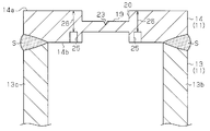
- FIG. 3 is a sectional view taken along line 3-3 in FIG. 1.
- Sectional drawing which shows the state which has arrange
- the top view of the cover in another example.
- a secondary battery 10 as a power storage device includes a case 11 and an electrode assembly 12 accommodated in the case 11.
- the case 11 also contains an electrolyte solution together with the electrode assembly 12.
- the case 11 includes a case body 13 having an opening 13x and a plate-like lid body 14 that closes the opening 13x.
- the electrode assembly 12 is inserted into the case body 13 through the opening 13x.
- Both the case main body 13 and the lid body 14 are made of aluminum.
- the secondary battery 10 of this embodiment is a lithium ion battery.
- the case main body 13 has a bottomed rectangular tube shape and includes a rectangular flat plate-like bottom wall 13a and side walls 13b, 13c, 13d, and 13e that are erected from four sides of the bottom wall 13a.
- the bottom wall 13 a faces the lid body 14 that closes the opening 13 x of the case body 13.
- two sides on which the side walls 13b and 13c facing each other are erected are long sides, and two sides on which the side walls 13d and 13e facing each other are erected are short sides.
- the lid body 14 has a rectangular plate shape, and has two long sides extending along the side walls 13b and 13c of the case main body 13 in a state in which the opening 13x of the case main body 13 is closed, along the side walls 13d and 13e.
- the two sides that extend are the short sides.
- the secondary battery 10 of this embodiment is a prismatic battery whose appearance is square.
- the lid body 14 is joined to the opening 13 x of the case body 13.
- the case main body 13 and the lid body 14 are joined by welding (for example, laser welding).
- welding for example, laser welding
- the junction part S is provided over these perimeters.
- the joining portion S joins the side walls 13b to 13e of the case main body 13 and the lid body 14, and extends in the longitudinal direction and the short side direction of the case 11, respectively.
- the electrode assembly 12 has a positive electrode, a negative electrode, and a separator that insulates the positive electrode and the negative electrode.
- the positive electrode is configured by applying a positive electrode active material to both surfaces of a positive metal foil (aluminum foil).
- the negative electrode is configured by applying a negative electrode active material to both surfaces of a negative electrode metal foil (copper foil).
- the electrode assembly 12 has a stacked structure in which a plurality of positive electrodes and a plurality of negative electrodes are alternately stacked and a separator is interposed between adjacent electrodes.
- a positive electrode terminal 15 and a negative electrode terminal 16 are electrically connected to the electrode assembly 12. Each part of the positive electrode terminal 15 and the negative electrode terminal 16 is exposed to the outside of the case 11 from the lid body 14. Further, a ring-shaped insulating ring 17 a for insulating from the case 11 is attached to the positive terminal 15 and the negative terminal 16, respectively.
- the lid 14 of the case 11 When the pressure in the case 11 reaches a predetermined open pressure, the lid 14 of the case 11 is cleaved so that the inside and outside of the case 11 communicate with each other so that the pressure in the case 11 does not increase too much.
- the release pressure of the pressure release valve 18 is set to a pressure at which the pressure release valve 18 can be broken before the case 11 itself or the joint S can be cracked or broken.
- the pressure release valve 18 has a thin plate-like valve body 19 that is thinner than the plate thickness of the lid body 14.
- the valve body 19 is located at the bottom of the concave portion 20 provided in the upper surface of the lid body 14 and is formed integrally with the lid body 14.
- the pressure release valve 18 is an integral part of the lid body 14.
- the valve body 19 of this embodiment has a track shape in which arc portions 22a and 22b are connected to two parallel straight portions 21a and 21b.
- a groove 23 is formed in the surface of the valve body 19 located outside the case 11.
- the groove 23 of this embodiment has a V-shaped cross section, and is formed by intersecting two linear grooves in an X shape.
- the pressure release valve 18 (valve body 19) is located at the center of the lid body 14.
- the lid 14 of the case 11 has a first recess 24 and a second recess 25 in a region surrounding the pressure release valve 18.
- the first recess 24 opens to the surface 14 a of the lid body 14 located outside the case 11 and is recessed toward the inside of the case 11.
- the second recess 25 is open to the back surface 14 b of the lid body 14 located inside the case 11, and is recessed toward the outside of the case 11.
- the recesses 24 and 25 of this embodiment have a rectangular cross section.
- the recesses 24 and 25 are annularly provided so as to surround the entire circumference of the pressure release valve 18. That is, the recesses 24 and 25 are provided in a surrounding region that is a region surrounding the pressure release valve 18 in the lid body 14.
- the enclosed region is a virtual annular region that exists between the inner periphery of the pressure release valve 18 and the outer periphery spaced from the inner periphery by a predetermined distance.
- the first recess 24 and the second recess 25 are provided at positions that overlap each other when viewed from the thickness direction of the lid body 14. That is, the second recess 25 is located on the opposite side of the first recess 24. Accordingly, the lid body 14 has a thin portion 26 thinner than the plate thickness of the lid body 14 between the bottom of the first recess 24 and the bottom of the second recess 25. That is, the portion where the plate thickness of the lid 14 is reduced by the first recess 24 and the second recess 25 forms the thin portion 26. Further, the front surface 14 a and the back surface 14 b of the lid body 14 are divided by the recesses 24 and 25 into the region where the pressure release valve 18 is located and the surrounding region.
- the concave portions 24 and 25 located between the straight portions 21 a and 21 b of the valve body 19 and the long sides of the lid body 14 facing the straight portions 21 a and 21 b correspond to the arc portions 22 a of the valve body 19.
- 22b and the concave portions 24, 25 located between the short sides of the lid body 14 opposite thereto are portions having a smaller interval with respect to the joint portion S. That is, in the enclosed area surrounding the pressure release valve 18 in the lid body 14, the recesses 24, 25 located between the straight portions 21 a, 21 b of the valve body 19 and the long sides of the lid body 14 opposed to the linear portions 21 a, 21 b.
- the portion is a portion having the smallest interval with respect to the joint portion S.
- the joint interface between the case body 13 and the lid body 14 is formed between the back surface 14b of the lid body 14 and the tips of the side walls 13b to 13e of the case body 13 facing the back surface 14b.
- the second recess 25 is a portion closer to the joint S than the first recess 24.
- the electrode assembly 12 is accommodated in the case main body 13 from the opening 13 x of the case main body 13, and then the opening 13 x of the case main body 13 is closed by the lid 14. Further, after the case body 13 is closed with the lid body 14, the electrolytic solution is injected from a liquid injection hole (not shown) provided on the wall surface of the case 11, and the liquid injection hole is sealed with a sealing member.
- the recesses 24 and 25 located around the pressure release valve 18 form a thin portion 26 in the lid 14.
- the region of the lid 14 existing around the pressure release valve 18 can serve as the heat transfer paths X and Y of the welding heat as described above.
- the thin portion 26 formed by the recesses 24 and 25 reduces the cross-sectional area of the surrounding region surrounding the pressure release valve 18, that is, the cross-sectional area of the heat transfer paths X and Y, so Reduce the amount of heat transferred.
- a thin portion 26 thinner than the plate thickness of the lid body 14 is provided in a surrounding area surrounding the pressure release valve 18 in the lid body 14.
- the thin portion 26 can reduce the cross-sectional areas of the heat transfer paths X and Y in the lid body 14 through which the welding heat generated when the case body 13 and the lid body 14 are joined by welding. For this reason, the thin portion 26 can make it difficult to transmit the welding heat to the pressure release valve 18.
- the pressure release valve 18 can be opened with an appropriate opening pressure. That is, it is difficult for the operating pressure to decrease or vary when the pressure release valve 18 is cleaved.
- the thin part 26 is provided by the recessed parts 24 and 25 recessed around the pressure release valve 18. For this reason, the thin part 26 can be reliably provided in the cover body 14, and welding heat can be made difficult to be transmitted to the pressure release valve 18. Further, the thin portion 26 can be easily provided by the concave portions 24 and 25.
- Concave portions 24 and 25 that are opened on the front surface 14a and the back surface 14b of the lid body 14 are provided, respectively, and a portion where the plate thickness of the lid body 14 is reduced by the concave portions 24 and 25 is a thin portion 26. . According to this, compared with the case where a recessed part is provided so that it may open only to one surface of the cover body 14, the thinner thin part 26 can be provided. Therefore, it is possible to make it difficult to transmit the welding heat to the pressure release valve 18.
- the second concave portion 25 is provided on the back surface 14b located at least on the same side as the joint portion S of the front surface 14a and the back surface 14b of the lid body 14. According to this, the distance between the joint portion S and the thin portion 26 can be increased, and the welding heat can be more difficult to be transmitted to the pressure release valve 18.
- the recesses 24 and 25 are formed in an annular shape surrounding the pressure release valve 18. Therefore, the cross-sectional areas of the heat transfer paths X and Y can be reduced over a wide range, and the welding heat can be more difficult to be transmitted to the pressure release valve 18.
- the lid 14 is provided with a thin portion 26 that is thinner than the plate thickness of the lid 14 between the bottom of the recess 25 and the surface 14 a of the lid 14 positioned outside the case 11. That is, the portion where the plate thickness of the lid body 14 is reduced by the concave portion 25 forms the thin portion 26.
- the recessed part 25 in this embodiment is also annularly recessed so that the surroundings of the pressure release valve 18 may be enclosed similarly to the said 1st Embodiment.
- a jig 40 is disposed on the lid 14 when the case main body 13 and the lid 14 are joined by welding.
- the jig 40 is made of copper and has the same size as the lid 14.
- tool 40 is arrange
- the jig 40 is disposed on the lid 14.
- copper which is the material of the jig 40
- aluminum which is the material of the lid body 14.
- welding heat is easily transmitted to the jig 40.
- a jig 40 made of a material having a higher thermal conductivity than that of the material constituting the lid 14 is brought into contact. According to this, welding heat can be transmitted to the jig 40 when the case main body 13 and the lid body 14 are joined by welding. Furthermore, the recessed part 25 is provided in the back surface 14b which is a surface by the side of the junction part S among the surface 14a and the back surface 14b of the cover body 14.
- a plurality of recesses 30 may be provided in the lid body 14.
- the plurality of recesses 30 extend in a straight line and are provided in a part of a surrounding region surrounding the pressure release valve 18.
- Each recess 30 extends along the straight portions 21 a and 21 b of the valve body 19 of the pressure release valve 18. And these recessed parts 30 are extended in the direction where the long side of the cover body 14 is extended.
- FIG. 6 when the lid body 14 has a rectangular flat plate shape and the pressure release valve 18 is arranged in the center of the lid body 14, the short side of the lid body 14 is opposed to the surrounding area surrounding the pressure release valve 18. The part facing the long side is closer to the welded part S than the part to be done. That is, as shown in FIG.
- the recess has a function of thermally shutting off the valve body 19 of the pressure release valve 18 from other parts of the lid body 14, and therefore when the recess is provided along a part of the outer periphery of the pressure release valve 18. It is preferable to provide in the position which can satisfy the heat shut-off function mentioned above.
- the recess 30 may be provided only on the front surface 14a of the lid body 14, or may be provided only on the back surface 14b of the lid body 14, or may be provided on both the front surface 14a and the back surface 14b of the lid body 14. It may be provided.
- valve body 19 of the pressure release valve 18 is located, for example, near one short side of the lid body 14, and a portion of the pressure release valve 18 facing the one short side is close to the joint S. In such a case, you may provide a recessed part along the one short side.
- the lid 14 according to the first embodiment may be provided with only a first recess 24 that opens on the surface 14a of the lid 14.
- the lid 14 has a plate thickness of the lid 14 between the bottom of the first recess 24 and the back surface 14b of the lid 14 located inside the case 11 at the recessed position of the first recess 24.
- a thinner thin portion 26 is provided.
- an annular protrusion 32 may be provided around the valve body 19 of the pressure release valve 18 in the first embodiment.
- the protrusion 32 protrudes from each of the front surface 14 a and the back surface 14 b of the lid body 14.
- the protruding position of the protrusion 32 on the lid 14 is a thick portion 33 that is thicker than the plate thickness of the lid 14.
- the thick portion 33 functions as a member having a predetermined heat capacity that temporarily receives heat transmitted to the lid body 14. Thereby, since the heat of welding is absorbed in the thick part 33, it can be made difficult to transmit to the valve body 19.
- the jig 40 may be arranged on the lid 14 when the case body 13 and the lid 14 are joined by welding. Good. According to such a form, welding heat can be transmitted to the jig 40.
- welding may be performed without arranging the jig 40 on the lid body 14.
- welding heat can be radiated to the outside or the inside of the case 11.
- the amount of heat that moves from the top to the surface 14a side of the lid 14 increases. Therefore, heat radiation of the welding heat to the outside of the case 11 can be promoted.
- the size of the jig 40 may be larger than the size of the lid 14 or smaller than the lid 14. However, the larger the contact area of the jig 40 on the surface 14 a of the lid body 14, the more preferable is that the welding heat is transmitted by the jig 40.
- the jig 40 may be made of metal other than copper, such as silver. In short, any material having a higher thermal conductivity than the material constituting the lid 14 can be used as the material constituting the jig 40.
- the case body 13 and the lid body 14 may be made of metal other than aluminum, such as stainless steel.
- the position of the joint portion S that joins the case body 13 and the lid body 14 may be changed.
- the joint portion S may be provided on the surface 14 a of the lid body 14.
- the recesses 24, 25 and 30 are not limited to continuous recesses, but may be intermittent recesses.
- the recesses 24 and 25 may partially change the width and depth.
- the portions of the recesses 24 and 25 close to the joint S may be widened or deepened.
- the width and depth of the two recesses 30 may be different from each other, or the width and depth may be changed in the same recess 30.
- the shape of the valve body 19 of the pressure release valve 18 may be changed.
- an elliptical shape, a circular shape, or a rectangular shape may be used.
- the first end portions of two parallel straight portions may be connected by an arc portion, and the second end portions may be connected by a straight portion.
- the shape of the groove 23 of the valve body 19 of the pressure release valve 18 may be changed.
- a groove in which three linear grooves are connected in a Y shape may be used.
- the appearance of the case 11 may be changed.
- the case 11 may have a rectangular shape, a rectangular parallelepiped shape, a cubic shape, or a cylindrical shape.
- the electrode assembly 12 is not limited to the laminated type, and may be a wound type in which a belt-like positive electrode and a belt-like negative electrode are wound and laminated in layers.
- the secondary battery 10 is a lithium ion secondary battery, but is not limited thereto, and may be another secondary battery. In short, any ion may be used as long as ions move between the positive electrode active material layer and the negative electrode active material layer and transfer charge.
- the power storage device may be a capacitor.
- the secondary battery 10 may be mounted on a vehicle as a vehicle power supply device, or may be mounted on an industrial vehicle. Further, the present invention may be applied to a stationary power storage device.
Landscapes
- Chemical & Material Sciences (AREA)
- Chemical Kinetics & Catalysis (AREA)
- Electrochemistry (AREA)
- General Chemical & Material Sciences (AREA)
- Engineering & Computer Science (AREA)
- Manufacturing & Machinery (AREA)
- Power Engineering (AREA)
- Microelectronics & Electronic Packaging (AREA)
- Gas Exhaust Devices For Batteries (AREA)
- Sealing Battery Cases Or Jackets (AREA)
- Electric Double-Layer Capacitors Or The Like (AREA)
Abstract
蓄電装置は、電極組立体と、前記電極組立体を収容するケースと、を備える。前記ケースは、開口部を有するケース本体と、前記開口部を塞ぐ板状の蓋体と、前記ケース本体と前記蓋体とが溶接されている接合部と、を含み、前記蓋体は、該蓋体と一体に形成されるとともに、前記ケース内の圧力をケース外に開放させるように構成される圧力開放弁を有する。前記蓋体は、前記圧力開放弁を囲む囲み領域を有し、前記囲み領域は、少なくとも該囲み領域と前記接合部との間隔が最も小さい部分に、前記蓋体の板厚よりも薄い肉薄部、又は前記蓋体の板厚よりも厚い肉厚部を有する。
Description
この発明は、ケース内の圧力をケース外に開放させる圧力開放弁を有する蓄電装置、及び蓄電装置の製造方法に関する。
EV(Electric Vehicle)やPHV(Plug in Hybrid Vehicle)などの車両には、原動機となる電動機への供給電力を蓄える蓄電装置としてリチウムイオン電池などの二次電池が搭載されている。この種の二次電池は、例えば、特許文献1に開示されている。二次電池は、ケース本体に電極組立体や電解液などの電池要素を収容し、そのケース本体の開口部を蓋体で閉塞している。また、二次電池には、蓋体などにケース内の圧力をケース外に開放させる圧力開放弁が設けられている。
ところで、二次電池は、気密性を高める必要がある。このため、二次電池を製造する際、ケース本体と蓋体を接合する場合や、特許文献1のように別体とされた圧力開放弁を蓋体に接合する場合などには、例えばレーザ溶接などの溶接が行われる。しかしながら、溶接をすると、その溶接熱によって圧力開放弁の開放圧が変化する虞がある。これは、溶接熱の影響を受けて圧力開放弁の構成材料の温度が上昇し、構成材料を軟化させてしまうことに起因する。圧力開放弁の開放圧が変化してしまうと、圧力開放弁を適切な開放圧で開放させることができない虞がある。
この発明の目的は、圧力開放弁を適切な開放圧で開放し得る蓄電装置及び蓄電装置の製造方法を提供することにある。
上記課題を解決する蓄電装置は、電極組立体と、前記電極組立体を収容するケースと、を備える。前記ケースは、開口部を有するケース本体と、前記開口部を塞ぐ板状の蓋体と、前記ケース本体と前記蓋体とが溶接されている接合部と、を含み、前記蓋体は、該蓋体と一体に形成されるとともに、前記ケース内の圧力をケース外に開放させるように構成される圧力開放弁を有する。前記蓋体は、前記圧力開放弁を囲む囲み領域を有し、前記囲み領域は、少なくとも該囲み領域と前記接合部との間隔が最も小さい部分に、前記蓋体の板厚よりも薄い肉薄部、又は前記蓋体の板厚よりも厚い肉厚部を有する。
この構成によれば、圧力開放弁を囲む囲み領域に蓋体の板厚よりも薄い肉薄部、又は蓋体の板厚よりも厚い肉厚部を設ける。肉薄部を設けた場合は、その肉薄部により、ケース本体と蓋体を溶接で接合する際の溶接熱が蓋体に伝わる伝熱経路の断面積を減少させることができる。このため、肉薄部を囲み領域に設けることで、溶接熱を圧力開放弁側へ伝わり難くすることができる。また、肉厚部を設けた場合は、その肉厚部が、ケース本体と蓋体を溶接で接合する際の溶接熱を一時的に吸収する部材として機能する。このため、肉厚部を囲み領域に設けることで、溶接熱を圧力開放弁側へ伝わり難くすることができる。その結果、肉薄部又は肉厚部を設けることにより、熱の影響による圧力開放弁の開放圧の変化を抑制し得る。したがって、圧力開放弁を適切な開放圧で開放させることができる。
上記蓄電装置において、前記囲み領域は、前記蓋体の厚み方向に凹んだ凹部を有し、前記凹部によって前記肉薄部が形成される。この構成によれば、凹部によって肉薄部を確実に設けることができ、溶接熱を圧力開放弁側へ伝わり難くすることができる。
上記蓄電装置において、前記凹部は、前記蓋体の表面及び裏面のうち、前記接合部側の面に少なくとも開口していることが好ましい。この構成によれば、接合部と肉薄部の距離を遠ざけることができ、溶接熱を圧力開放弁側へより伝わり難くすることができる。
上記蓄電装置において、前記凹部は、前記蓋体の表面及び裏面のうち、前記接合部側の面にのみ開口していることが好ましい。この構成によれば、ケース本体と蓋体が溶接で接合される際に、溶接熱が蓋体に伝わる伝熱経路を、蓋体におけるケースの外側に近い位置とすることができる。したがって、ケースの外側への溶接熱の放熱を促すことができ、溶接熱を圧力開放弁側へ伝わり難くすることができる。
上記蓄電装置において、前記蓋体は、前記凹部は、前記蓋体の表面に開口する第1凹部と前記蓋体の裏面に開口する第2凹部とを含み、前記第1及び第2凹部が前記蓋体の厚み方向から見て互いに重なることが好ましい。この構成によれば、蓋体の厚み方向から見て重なる位置で、蓋体の表裏両面に開口する凹部によってさらに薄い肉薄部を設けることができる。このため、溶接熱を圧力開放弁側へより伝わり難くすることができる。
上記蓄電装置において、前記凹部は、前記圧力開放弁を囲む環状であることが好ましい。この構成によれば、環状の凹部によって圧力開放弁を囲むように肉薄部を設けることができる。したがって、広範囲に亘って伝熱経路の断面積を減少させることができ、溶接熱を圧力開放弁側へより伝わり難くすることができる。
上記蓄電装置において、前記蓄電装置の好適な例としては、二次電池を挙げることができる。
上記課題を解決する蓄電装置の製造方法は、電極組立体を収容するケースを備えた蓄電装置の製造方法であって、開口部を有するケース本体と、前記ケース本体の前記開口部を塞ぐ板状の蓋体と、を含む前記ケースを、前記ケース本体と前記蓋体とを接合部において溶接するために準備することと、前記ケース内の圧力をケース外に開放させる圧力開放弁を前記蓋体と一体的に形成することと、前記蓋体における前記圧力開放弁を囲む囲み領域のうち、少なくとも該囲み領域と前記接合部との間隔が最も小さい部分に凹部を形成することであって、前記凹部によって前記蓋体には肉薄部が形成され、前記凹部は、前記蓋体の表面及び裏面のうち、前記接合部側の面にのみ開口していることと、前記蓋体の表面及び裏面のうち、前記接合部側の面とは反対側の面に、前記蓋体を構成する材料よりも熱伝導率の高い材料で構成される治具を接触させた状態で、前記ケース本体と前記蓋体とを溶接することと、を備える。
この構成によれば、ケース本体と蓋体を溶接によって接合するときに、蓋体の表面及び裏面のうち、接合部側の面とは反対側の面に、蓋体を構成する材料よりも熱伝導率の高い材料で構成される治具を接触させる。このため、ケース本体と蓋体が溶接で接合される際に、溶接熱を治具に伝達させることができる。更に、上記構成の凹部は、蓋体の表面及び裏面のうち、接合部側の面にのみ開口しているため、ケース本体と蓋体を溶接で接合する際に、溶接熱が蓋体に伝わる伝熱経路を、蓋体におけるケースの外側に近い位置とすることができる。したがって、蓋体における溶接熱の伝熱経路を治具に近づけることができるため、治具への溶接熱の伝達を促すことができる。このため、溶接熱を圧力開放弁側へ伝わり難くすることができる。その結果、熱の影響による圧力開放弁の開放圧の変化を抑制し得るため、圧力開放弁を適切な開放圧で開放させることができる。
(第1の実施形態)
以下、蓄電装置の第1の実施形態を図1~図3にしたがって説明する。
以下、蓄電装置の第1の実施形態を図1~図3にしたがって説明する。
図1に示すように、蓄電装置としての二次電池10は、ケース11と、ケース11に収容された電極組立体12とを有する。また、ケース11には、電極組立体12とともに電解液も収容されている。ケース11は、開口部13xを有するケース本体13と、開口部13xを閉塞する板状の蓋体14とを含む。電極組立体12は、開口部13xを通ってケース本体13に挿入される。ケース本体13と蓋体14は、何れもアルミニウム製である。この実施形態の二次電池10は、リチウムイオン電池である。
ケース本体13は、有底四角筒状であり、矩形平板状の底壁13aとその底壁13aの四辺から立設された側壁13b,13c,13d,13eを有する。底壁13aは、ケース本体13の開口部13xを塞ぐ蓋体14と対向する。底壁13aの四辺のうち、互いに対向する側壁13b,13cが立設される二辺が長辺であり、互いに対向する側壁13d,13eが立設される二辺が短辺である。蓋体14は、矩形板状であり、ケース本体13の開口部13xを塞いだ状態において、ケース本体13の側壁13b,13cに沿って延びる二辺が長辺であり、側壁13d,13eに沿って延びる二辺が短辺である。この実施形態の二次電池10は、その外観が角型をなす角型電池である。
そして、二次電池10において、ケース本体13の開口部13xには蓋体14が接合される。この実施形態においてケース本体13と蓋体14は、溶接(例えば、レーザ溶接)によって接合される。このため、図1に示すように、ケース本体13と蓋体14との間には、これらの全周に亘って溶接による接合部Sが設けられる。接合部Sは、ケース本体13の各側壁13b~13eと蓋体14とをそれぞれ接合し、ケース11の長手方向及び短手方向にそれぞれ延在されている。
電極組立体12は、正極電極、負極電極、及び正極電極と負極電極を絶縁するセパレータを有する。正極電極は、正極金属箔(アルミニウム箔)の両面に正極活物質を塗布して構成される。負極電極は、負極金属箔(銅箔)の両面に負極活物質を塗布して構成される。そして、電極組立体12は、複数の正極電極と複数の負極電極を交互に積層するとともに、隣り合う電極の間にセパレータを介在した積層構造とされている。また、電極組立体12には、正極端子15と負極端子16が電気的に接続されている。これらの正極端子15と負極端子16の各一部分は、蓋体14からケース11外に露出している。また、正極端子15及び負極端子16には、ケース11から絶縁するためのリング状の絶縁リング17aがそれぞれ取り付けられている。
ケース11の蓋体14には、ケース11内の圧力が上昇し過ぎないように、ケース11内の圧力が所定の開放圧に達した場合に、ケース11の内外を連通させるように開裂することによってケース11内の圧力をケース11外に開放させる圧力開放弁18が設けられている。圧力開放弁18の開放圧は、ケース11自体や接合部Sに亀裂や破断などが生じ得る前に圧力開放弁18が開裂し得る圧力に設定されている。
図2及び図3に示すように、圧力開放弁18は、蓋体14の板厚よりも薄い薄板状の弁体19を有する。弁体19は、蓋体14の上面に凹設された凹状部20の底に位置しており、蓋体14と一体的に成形されている。これにより、圧力開放弁18は、蓋体14との一体品となる。この実施形態の弁体19は、平行な2つの直線部21a,21bに弧部22a,22bを繋げたトラック形状である。また、ケース11の外側に位置する弁体19の表面には、溝23が凹設されている。この実施形態の溝23は、断面V字状であり、2本の直線溝をX字状に交差させて形成されている。この実施形態において圧力開放弁18(弁体19)は、蓋体14の中央に位置している。
また、ケース11の蓋体14は、圧力開放弁18を囲む領域に第1凹部24及び第2凹部25を有している。第1凹部24は、ケース11の外側に位置する蓋体14の表面14aに開口しており、ケース11の内側に向かって凹んでいる。一方、第2凹部25は、ケース11の内側に位置する蓋体14の裏面14bに開口しており、ケース11の外側に向かって凹んでいる。この実施形態の凹部24,25は、断面矩形状である。そして、凹部24,25は、圧力開放弁18の全周を囲うように環状に凹設されている。つまり、凹部24,25は、蓋体14において圧力開放弁18を囲む領域である囲み領域に設けられる。なお、囲み領域とは、圧力開放弁18の外周縁を内周とし、その内周と同内周から所定の間隔を隔てた外周との間に存在する仮想的な環状の領域である。また、第1凹部24と第2凹部25とは、蓋体14の厚み方向から見て互いに重なる位置に設けられている。つまり、第2凹部25は、第1凹部24の反対側に位置している。これにより、蓋体14は、第1凹部24の底と第2凹部25の底の間に蓋体14の板厚よりも薄い肉薄部26を有する。つまり、第1凹部24と第2凹部25とによって蓋体14の板厚が薄くなった部分が肉薄部26をなす。また、蓋体14の表面14a及び裏面14bは、圧力開放弁18が位置する領域とその周囲の領域とが凹部24,25によって分割される。
なお、この実施形態では、弁体19の各直線部21a,21bとそれに対向する蓋体14の各長辺との間に位置する凹部24,25の部分が、弁体19の各弧部22a,22bとそれに対向する蓋体14の各短辺との間に位置する凹部24,25の部分よりも、接合部Sに対する間隔が小さい部分となる。つまり、蓋体14において圧力開放弁18を囲む前記囲み領域のうち、弁体19の各直線部21a,21bとそれに対向する蓋体14の各長辺との間に位置する凹部24,25の部分は、接合部Sに対する間隔が最も小さい部分である。また、この実施形態において、ケース本体13と蓋体14との接合界面は、蓋体14の裏面14bとその裏面14bに対向するケース本体13の各側壁13b~13eの先端との間に形成される。このため、第2凹部25は、第1凹部24に比較して、接合部Sに対する間隔が近い部分である。
以下、本実施形態の作用を説明する。
二次電池10において、ケース本体13の開口部13xから電極組立体12がケース本体13内に収容され、その後にケース本体13の開口部13xが蓋体14で閉塞される。また、電解液は、ケース本体13を蓋体14で閉塞した後、ケース11の壁面に設けた図示しない注液孔から注入されるとともにその注液孔が封止部材で封止される。
そして、ケース本体13の開口部13xを蓋体14で閉塞する場合には、ケース本体13と蓋体14とを溶接して接合する。このとき、溶接熱は、接合箇所から側壁13b~13eや蓋体14へ拡散する。そして、蓋体14には、全周から蓋体14の中央に向けて熱が伝わる。つまり、溶接時において蓋体14には、図2に示すように、蓋体14の周縁から中央に向かう伝熱経路X,Yが生じ得る。そして、蓋体14に伝わる熱は、蓋体14の周縁から圧力開放弁18の弁体19に向けて伝わる。なお、図2に示すように、蓋体14の長辺からの伝熱経路Xは、短辺からの伝熱経路Yよりも短い。つまり、溶接熱は、弁体19の直線部21a,21bの方に伝わり易い。
しかしながら、この実施形態では、圧力開放弁18の周囲に位置する凹部24,25が、蓋体14に肉薄部26を形成している。圧力開放弁18の周囲に存在する蓋体14の領域は、前述したように、溶接熱の伝熱経路X,Yとなり得る。しかし、凹部24,25による肉薄部26が、圧力開放弁18を囲む囲み領域の断面積、すなわち伝熱経路X,Yの断面積を小さくして、蓋体14の周縁から圧力開放弁18に伝わる熱量を減少させる。
したがって、本実施形態によれば、以下に示す効果を得ることができる。
(1)蓋体14において圧力開放弁18を囲む囲み領域に、蓋体14の板厚よりも薄い肉薄部26を設けている。この肉薄部26により、ケース本体13と蓋体14とを溶接で接合する際に発生する溶接熱が伝わる蓋体14における伝熱経路X,Yの断面積を減少させることができる。このため、肉薄部26によって、溶接熱を圧力開放弁18へ伝わり難くすることができる。その結果、熱の影響によって圧力開放弁18の温度が上昇することによる開放圧の変化を抑制し得る。したがって、圧力開放弁18を適切な開放圧で開放させることができる。つまり、圧力開放弁18が開裂する際の作動圧の低下やバラツキなどが生じ難い。
(2)また、圧力開放弁18の周囲に凹設した凹部24,25によって肉薄部26を設けている。このため、蓋体14に確実に肉薄部26を設けることができ、溶接熱を圧力開放弁18へ伝わり難くすることができる。また、凹部24,25により、肉薄部26を容易に設けることができる。
(3)蓋体14の表面14aと裏面14bとのそれぞれに開口する凹部24,25を設け、その凹部24,25によって蓋体14の板厚が薄くなった部分が肉薄部26となっている。これによれば、凹部を蓋体14の一方の面のみに開口するように設ける場合に比して、さらに薄い肉薄部26を設けることができる。したがって、溶接熱を圧力開放弁18へより伝わり難くすることができる。
(4)第2凹部25は、蓋体14の表面14aと裏面14bのうち、少なくとも接合部Sと同じ側に位置する裏面14bに設けられている。これによれば、接合部Sと肉薄部26との距離を遠ざけることができ、溶接熱を圧力開放弁18へより伝わり難くすることができる。
(5)凹部24,25を、圧力開放弁18を囲む環状としている。したがって、広範囲に亘って伝熱経路X,Yの断面積を減少させることができ、溶接熱を圧力開放弁18へより伝わり難くすることができる。
(第2の実施形態)
以下、蓄電装置を具体化した第2の実施形態を図4及び図5にしたがって説明する。なお、以下で説明する実施形態では、既に説明した第1の実施形態と同一構成について同一符号を付すなどして、その重複する説明を省略又は簡略する。
以下、蓄電装置を具体化した第2の実施形態を図4及び図5にしたがって説明する。なお、以下で説明する実施形態では、既に説明した第1の実施形態と同一構成について同一符号を付すなどして、その重複する説明を省略又は簡略する。
図4に示すように、本実施形態における二次電池10では、ケース11の蓋体14に、蓋体14の裏面14bに開口する凹部25のみが凹設されている。これにより、蓋体14には、凹部25の底とケース11の外側に位置する蓋体14の表面14aとの間に、蓋体14の板厚よりも薄い肉薄部26が設けられる。つまり、凹部25によって蓋体14の板厚が薄くなった部分が肉薄部26をなす。なお、本実施形態における凹部25も、上記第1の実施形態と同様に、圧力開放弁18の全周を囲むように環状に凹設されている。
図5に示すように、この実施形態では、ケース本体13と蓋体14の溶接による接合を行う際に、蓋体14上に治具40が配置される。治具40は銅製であり、蓋体14の大きさと同程度の大きさを有している。そして、治具40は、蓋体14の表面14a全体と接触するように蓋体14上に配置される。
以下、本実施形態の作用を説明する。
ケース本体13と蓋体14の溶接を行うに際して、蓋体14上に治具40を配置させる。ここで、治具40の材料である銅は、蓋体14の材料であるアルミニウムよりも熱伝導率が高い。このため、蓋体14上に治具40を配置した状態では、溶接熱が治具40に伝達され易くなる。また、蓋体14の裏面14bに開口する凹部25によって、溶接熱が蓋体14に伝わる伝熱経路X,Yにおいて、溶接部から蓋体14の表面14a側を経て治具40に移動する熱量が多くなる(図5の鎖線参照)。そして、ケース本体13と蓋体14の溶接による接合が終了すると、蓋体14から治具40が取り外される。
したがって、本実施形態によれば、上述した第1の実施形態で得ることのできる効果(1)、(2)、(4)及び(5)に加えて以下の効果を得ることができる。
(6)ケース本体13と蓋体14とが溶接によって接合されるときに、蓋体14の表面14aと裏面14bのうち、接合部S側の面とは反対側の面である表面14aに、蓋体14を構成する材料よりも熱伝導率の高い材料で構成される治具40を接触させている。これによれば、ケース本体13と蓋体14が溶接で接合される際に、溶接熱を治具40に伝達させることができる。更に、凹部25は、蓋体14の表面14aと裏面14bのうち、接合部S側の面である裏面14bに設けられている。これによれば、溶接熱が蓋体14に伝わる伝熱経路X,Yを治具40に近づけることができるため、治具40への溶接熱の伝達を促すことができる。このため、溶接熱を圧力開放弁18側へ伝わり難くすることができる。
なお、上記の各実施形態は以下のように変更してもよい。
図6に示すように、蓋体14に複数の凹部30を設けても良い。複数の凹部30は、直線状に延在されており、圧力開放弁18を囲む囲み領域の一部に設けられている。各凹部30は、圧力開放弁18の弁体19の直線部21a,21bに沿って延びている。そして、これらの凹部30は、蓋体14の長辺の延びる方向に延在されている。図6に示すように、蓋体14を矩形平板状とし、圧力開放弁18を蓋体14の中央に配置した場合、圧力開放弁18を囲む囲み領域のうち、蓋体14の短辺と対向する部分よりも長辺と対向する部分の方が、溶接部Sに近い。つまり、図6に示すように、圧力開放弁18の弁体19がトラック形状であり、その直線部21a,21bを蓋体14の長辺に沿わせた場合、囲み領域において接合部Sに最も近い部分は、弁体19の直線部21a,21bに隣接する部分となる。このため、この別例では、凹部30を弁体19の直線部21a,21bに沿わせて凹設し、その凹部30の形成された部位に肉薄部26を設けている。このように、上記実施形態のように圧力開放弁18の外周全体を囲む凹部24,25に代えて、圧力開放弁18の外周の一部に沿って延びる凹部30を設けても良い。なお、凹部は、圧力開放弁18の弁体19を蓋体14の他の部位から熱的に遮断させる機能を有するので、圧力開放弁18の外周の一部に沿って凹部を設ける場合には前述した熱遮断機能を充足し得る位置に設けることが好ましい。また、この別例において凹部30は、蓋体14の表面14aのみに設けても良いし、蓋体14の裏面14bのみに設けても良いし、蓋体14の表面14aと裏面14bの両面に設けても良い。
また、圧力開放弁18の弁体19が、例えば、蓋体14の一方の短辺寄りに位置しており、圧力開放弁18においてその一方の短辺に対向する部分が接合部Sに近くなるような場合、凹部をその一方の短辺に沿うように設けても良い。
図7に示すように、第1の実施形態における蓋体14には、蓋体14の表面14aに開口する第1凹部24のみを凹設しても良い。この場合、蓋体14には、第1凹部24の凹設位置において当該第1凹部24の底とケース11の内側に位置する蓋体14の裏面14bとの間に、蓋体14の板厚よりも薄い肉薄部26が設けられる。
図8に示すように、第1の実施形態における圧力開放弁18の弁体19の周囲に環状の突部32を突設しても良い。突部32は、蓋体14の表面14a及び裏面14bのそれぞれから突設している。この場合、蓋体14における突部32の突設位置は、蓋体14の板厚よりも厚くなる肉厚部33となる。肉厚部33は、蓋体14に伝わる熱を一時的に受ける所定の熱容量を有する部材として機能する。これにより、溶接の熱は、肉厚部33で吸収されるので、弁体19へ伝わり難くすることができる。なお、突部32は、図6の別例で説明したように、圧力開放弁18の外周の一部のみに沿って設けても良い。
図3に示す第1の実施形態や、図6~図8の別例では、ケース本体13と蓋体14の溶接での接合に際して、蓋体14上に治具40を配置するようにしてもよい。こうした形態によれば、溶接熱を治具40に伝達させることができる。
また、図5に示す第2の実施形態において、蓋体14上に治具40を配置せずに溶接を行うようにしてもよい。こうした形態によれば、溶接熱を治具40に伝達させることはできないものの、溶接熱をケース11の外側や内側に放熱させることができる。蓋体14上に治具40を配置せずに溶接を行う場合では、蓋体14の裏面14bに開口する凹部25によって、溶接熱が蓋体14に伝わる伝熱経路X,Yにおいて、溶接部から蓋体14の表面14a側に移動する熱量が多くなる。よって、ケース11の外側への溶接熱の放熱を促すことができる。
治具40の大きさは蓋体14の大きさよりも大きくても良いし、蓋体14よりも小さくても良い。ただし、蓋体14の表面14a上への治具40の接触面積が大きいほど、溶接熱を治具40により伝達させる点で望ましい。
治具40は、銀等、銅以外の金属製としても良い。要するに、蓋体14を構成する材料よりも熱伝導率の高い材料であれば、治具40を構成する材料として採用可能である。
ケース本体13と蓋体14は、ステンレス等、アルミニウム以外の金属製としても良い。
ケース本体13と蓋体14とを接合する接合部Sの位置を変更しても良い。例えば、蓋体14の表面14aに接合部Sを設けても良い。
凹部24,25,30は、連続的な凹部に限らず、断続的な凹部でも良い。
凹部24,25は、部分的に幅や深さを変更しても良い。例えば、凹部24,25において接合部Sに近い部分は、その幅を広くしたり、深さを深くしても良い。また、同様に、図6で説明した別例において、2つの凹部30の幅や深さは互いに異なっていても良いし、同じ凹部30において幅や深さを変更しても良い。
圧力開放弁18の弁体19の形状を変更しても良い。例えば、楕円形状、円形状や四角形状でも良い。また、例えば、平行な2つの直線部の第1の端部同士を弧部で繋ぎ、第2の端部同士を直線部で繋ぐ、非対称形状でも良い。
圧力開放弁18の弁体19が有する溝23の形状を変更しても良い。例えば、3本の直線溝をY字状に接続させた溝でも良い。
ケース11の外観形状を変更しても良い。例えば、ケース11は角型として直方体状や立方体状でも良いし、円筒型でも良い。
電極組立体12は、積層型に限らず、帯状の正極電極と帯状の負極電極を捲回して層状に積層した捲回型でも良い。
二次電池10は、リチウムイオン二次電池であったが、これに限らず、他の二次電池であっても良い。要は、正極活物質層と負極活物質層との間をイオンが移動するとともに電荷の授受を行うものであれば良い。また、蓄電装置はキャパシタでも良い。
二次電池10は、車両電源装置として自動車に搭載しても良いし、産業用車両に搭載しても良い。また、定置用の蓄電装置に適用しても良い。
Claims (8)
- 電極組立体と、
前記電極組立体を収容するケースと、を備え、
前記ケースは、開口部を有するケース本体と、前記開口部を塞ぐ板状の蓋体と、前記ケース本体と前記蓋体とが溶接されている接合部と、を含み、
前記蓋体は、該蓋体と一体に形成されるとともに、前記ケース内の圧力をケース外に開放させるように構成される圧力開放弁を有し、
前記蓋体は、前記圧力開放弁を囲む囲み領域を有し、前記囲み領域は、少なくとも該囲み領域と前記接合部との間隔が最も小さい部分に、前記蓋体の板厚よりも薄い肉薄部、又は前記蓋体の板厚よりも厚い肉厚部を有する蓄電装置。 - 前記囲み領域は、前記蓋体の厚み方向に凹んだ凹部を有し、前記凹部によって前記肉薄部が形成される請求項1に記載の蓄電装置。
- 前記凹部は、前記蓋体の表面及び裏面のうち、前記接合部側の面に少なくとも開口している請求項2に記載の蓄電装置。
- 前記凹部は、前記蓋体の表面及び裏面のうち、前記接合部側の面にのみ開口している請求項3に記載の蓄電装置。
- 前記凹部は、前記蓋体の表面に開口する第1凹部と前記蓋体の裏面に開口する第2凹部とを含み、
前記第1及び第2凹部が前記蓋体の厚み方向から見て互いに重なる請求項2又は請求項3に記載の蓄電装置。 - 前記凹部は、前記圧力開放弁を囲む環状である請求項2~請求項5のうち何れか一項に記載の蓄電装置。
- 前記蓄電装置は、二次電池である請求項1~請求項6のうち何れか一項に記載の蓄電装置。
- 電極組立体を収容するケースを備えた蓄電装置の製造方法であって、
開口部を有するケース本体と、前記ケース本体の前記開口部を塞ぐ板状の蓋体と、を含む前記ケースとを、前記ケース本体と前記蓋体とを接合部において溶接するために準備することと、
前記ケース内の圧力をケース外に開放させる圧力開放弁を前記蓋体と一体的に形成することと、
前記蓋体における前記圧力開放弁を囲む囲み領域のうち、少なくとも該囲み領域と前記接合部との間隔が最も小さい部分に凹部を形成することであって、前記凹部によって前記蓋体には肉薄部を形成し、前記凹部を、前記蓋体の表面及び裏面のうち、前記接合部側の面にのみ開口させることと、
前記蓋体の表面及び裏面のうち、前記接合部側の面とは反対側の面に、前記蓋体を構成する材料よりも熱伝導率の高い材料で構成される治具を接触させた状態で、前記ケース本体と前記蓋体とを溶接することと、を備える蓄電装置の製造方法。
Priority Applications (1)
| Application Number | Priority Date | Filing Date | Title |
|---|---|---|---|
| JP2014544583A JPWO2014069575A1 (ja) | 2012-11-02 | 2013-10-31 | 蓄電装置及び蓄電装置の製造方法 |
Applications Claiming Priority (2)
| Application Number | Priority Date | Filing Date | Title |
|---|---|---|---|
| JP2012-242925 | 2012-11-02 | ||
| JP2012242925 | 2012-11-02 |
Publications (1)
| Publication Number | Publication Date |
|---|---|
| WO2014069575A1 true WO2014069575A1 (ja) | 2014-05-08 |
Family
ID=50627473
Family Applications (1)
| Application Number | Title | Priority Date | Filing Date |
|---|---|---|---|
| PCT/JP2013/079568 Ceased WO2014069575A1 (ja) | 2012-11-02 | 2013-10-31 | 蓄電装置及び蓄電装置の製造方法 |
Country Status (2)
| Country | Link |
|---|---|
| JP (1) | JPWO2014069575A1 (ja) |
| WO (1) | WO2014069575A1 (ja) |
Cited By (12)
| Publication number | Priority date | Publication date | Assignee | Title |
|---|---|---|---|---|
| JP2016051656A (ja) * | 2014-09-01 | 2016-04-11 | 株式会社豊田自動織機 | 蓄電装置 |
| JP2016157769A (ja) * | 2015-02-24 | 2016-09-01 | Nok株式会社 | 防爆弁 |
| JP2017162570A (ja) * | 2016-03-07 | 2017-09-14 | 株式会社Gsユアサ | 蓄電素子 |
| WO2017208620A1 (ja) * | 2016-05-31 | 2017-12-07 | パナソニックIpマネジメント株式会社 | 封口体及びこれを用いた非水電解質二次電池 |
| CN109690819A (zh) * | 2016-09-20 | 2019-04-26 | 三星Sdi株式会社 | 具有压纹安全通气部的二次电池 |
| WO2021192544A1 (ja) * | 2020-03-27 | 2021-09-30 | 三洋電機株式会社 | 角形二次電池及びその製造方法 |
| EP3716391A4 (en) * | 2017-11-06 | 2022-02-23 | Eve Energy Co., Ltd. | SAFE AND HIGH ENERGY USB RECHARGEABLE BATTERY |
| WO2023065954A1 (zh) * | 2021-10-19 | 2023-04-27 | 宁德时代新能源科技股份有限公司 | 电池单体、电池及用电装置 |
| EP4468488A4 (en) * | 2022-01-27 | 2025-04-16 | Contemporary Amperex Technology Co., Limited | End cap assembly, battery cell, battery and power consuming device |
| EP4383431A4 (en) * | 2022-01-26 | 2025-04-23 | Contemporary Amperex Technology (Hong Kong) Limited | PRESSURE RELEASE APPARATUS, CELL, BATTERY AND ELECTRICAL DEVICE |
| EP4276988A4 (en) * | 2021-08-24 | 2025-06-18 | Contemporary Amperex Technology (Hong Kong) Limited | BATTERY CELL, BATTERY AND DEVICE USING THE BATTERY |
| WO2026000583A1 (zh) * | 2024-06-28 | 2026-01-02 | 宁德时代新能源科技股份有限公司 | 电池、用电装置、储能装置及电池制造方法 |
Families Citing this family (1)
| Publication number | Priority date | Publication date | Assignee | Title |
|---|---|---|---|---|
| JP7234908B2 (ja) * | 2019-11-26 | 2023-03-08 | 株式会社豊田自動織機 | 圧力調整弁構造及び蓄電モジュール |
Citations (8)
| Publication number | Priority date | Publication date | Assignee | Title |
|---|---|---|---|---|
| JPH01169333A (ja) | 1987-12-25 | 1989-07-04 | Hitachi Ltd | 半導体圧力変換器 |
| JPH0716198A (ja) | 1993-07-02 | 1995-01-20 | Shinichi Ono | 粘着ロ−ルクリ−ナ |
| JPH08212987A (ja) * | 1994-11-29 | 1996-08-20 | Toshiba Corp | 二次電池容器およびその製法 |
| JP2000149902A (ja) * | 1998-09-03 | 2000-05-30 | Sanyo Electric Co Ltd | 二次電池 |
| JP2002078664A (ja) | 2000-09-07 | 2002-03-19 | Akihiko Odagiri | 巻取り式粘着掃除機 |
| JP2003168405A (ja) * | 2001-12-03 | 2003-06-13 | Kyoto Seisakusho Co Ltd | 封口溶接方法 |
| JP2005332700A (ja) * | 2004-05-20 | 2005-12-02 | Toyota Motor Corp | 缶型電池およびその製造方法 |
| WO2010140436A1 (ja) * | 2009-06-04 | 2010-12-09 | トヨタ自動車株式会社 | 密閉型電池 |
-
2013
- 2013-10-31 WO PCT/JP2013/079568 patent/WO2014069575A1/ja not_active Ceased
- 2013-10-31 JP JP2014544583A patent/JPWO2014069575A1/ja active Pending
Patent Citations (8)
| Publication number | Priority date | Publication date | Assignee | Title |
|---|---|---|---|---|
| JPH01169333A (ja) | 1987-12-25 | 1989-07-04 | Hitachi Ltd | 半導体圧力変換器 |
| JPH0716198A (ja) | 1993-07-02 | 1995-01-20 | Shinichi Ono | 粘着ロ−ルクリ−ナ |
| JPH08212987A (ja) * | 1994-11-29 | 1996-08-20 | Toshiba Corp | 二次電池容器およびその製法 |
| JP2000149902A (ja) * | 1998-09-03 | 2000-05-30 | Sanyo Electric Co Ltd | 二次電池 |
| JP2002078664A (ja) | 2000-09-07 | 2002-03-19 | Akihiko Odagiri | 巻取り式粘着掃除機 |
| JP2003168405A (ja) * | 2001-12-03 | 2003-06-13 | Kyoto Seisakusho Co Ltd | 封口溶接方法 |
| JP2005332700A (ja) * | 2004-05-20 | 2005-12-02 | Toyota Motor Corp | 缶型電池およびその製造方法 |
| WO2010140436A1 (ja) * | 2009-06-04 | 2010-12-09 | トヨタ自動車株式会社 | 密閉型電池 |
Cited By (19)
| Publication number | Priority date | Publication date | Assignee | Title |
|---|---|---|---|---|
| JP2016051656A (ja) * | 2014-09-01 | 2016-04-11 | 株式会社豊田自動織機 | 蓄電装置 |
| JP2016157769A (ja) * | 2015-02-24 | 2016-09-01 | Nok株式会社 | 防爆弁 |
| JP2017162570A (ja) * | 2016-03-07 | 2017-09-14 | 株式会社Gsユアサ | 蓄電素子 |
| WO2017208620A1 (ja) * | 2016-05-31 | 2017-12-07 | パナソニックIpマネジメント株式会社 | 封口体及びこれを用いた非水電解質二次電池 |
| CN109690819B (zh) * | 2016-09-20 | 2021-10-26 | 三星Sdi株式会社 | 具有压纹安全通气部的二次电池 |
| US11031580B2 (en) | 2016-09-20 | 2021-06-08 | Samsung Sdi Co., Ltd. | Secondary battery with embossed safety vent |
| CN109690819A (zh) * | 2016-09-20 | 2019-04-26 | 三星Sdi株式会社 | 具有压纹安全通气部的二次电池 |
| EP3716391A4 (en) * | 2017-11-06 | 2022-02-23 | Eve Energy Co., Ltd. | SAFE AND HIGH ENERGY USB RECHARGEABLE BATTERY |
| US12009486B2 (en) | 2017-11-06 | 2024-06-11 | Eve Energy Co., Ltd. | Safe and high-energy USB rechargeable battery |
| JP7615123B2 (ja) | 2020-03-27 | 2025-01-16 | 三洋電機株式会社 | 角形二次電池及びその製造方法 |
| CN115210941A (zh) * | 2020-03-27 | 2022-10-18 | 三洋电机株式会社 | 方形二次电池及其制造方法 |
| CN115210941B (zh) * | 2020-03-27 | 2024-05-14 | 三洋电机株式会社 | 方形二次电池及其制造方法 |
| JPWO2021192544A1 (ja) * | 2020-03-27 | 2021-09-30 | ||
| WO2021192544A1 (ja) * | 2020-03-27 | 2021-09-30 | 三洋電機株式会社 | 角形二次電池及びその製造方法 |
| EP4276988A4 (en) * | 2021-08-24 | 2025-06-18 | Contemporary Amperex Technology (Hong Kong) Limited | BATTERY CELL, BATTERY AND DEVICE USING THE BATTERY |
| WO2023065954A1 (zh) * | 2021-10-19 | 2023-04-27 | 宁德时代新能源科技股份有限公司 | 电池单体、电池及用电装置 |
| EP4383431A4 (en) * | 2022-01-26 | 2025-04-23 | Contemporary Amperex Technology (Hong Kong) Limited | PRESSURE RELEASE APPARATUS, CELL, BATTERY AND ELECTRICAL DEVICE |
| EP4468488A4 (en) * | 2022-01-27 | 2025-04-16 | Contemporary Amperex Technology Co., Limited | End cap assembly, battery cell, battery and power consuming device |
| WO2026000583A1 (zh) * | 2024-06-28 | 2026-01-02 | 宁德时代新能源科技股份有限公司 | 电池、用电装置、储能装置及电池制造方法 |
Also Published As
| Publication number | Publication date |
|---|---|
| JPWO2014069575A1 (ja) | 2016-09-08 |
Similar Documents
| Publication | Publication Date | Title |
|---|---|---|
| JPWO2014069575A1 (ja) | 蓄電装置及び蓄電装置の製造方法 | |
| JP6124175B2 (ja) | 蓄電素子 | |
| KR102273642B1 (ko) | 이차 전지 | |
| WO2014084088A1 (ja) | 蓄電装置 | |
| JP2012009317A (ja) | リチウムイオン二次電池および組電池 | |
| JP2014102935A (ja) | 蓄電装置 | |
| JP2016219124A (ja) | 角形二次電池及びそれを用いた組電池、並びにその製造方法 | |
| JP6171943B2 (ja) | 蓄電装置 | |
| WO2015098955A1 (ja) | 蓄電装置 | |
| WO2017081838A1 (ja) | 電池パック | |
| KR102518352B1 (ko) | 이차 전지 | |
| WO2017090706A1 (ja) | 蓄電素子および蓄電モジュール | |
| WO2015137060A1 (ja) | 蓄電装置 | |
| WO2017038439A1 (ja) | 蓄電装置 | |
| JP5668772B2 (ja) | 蓄電装置 | |
| WO2014156474A1 (ja) | 蓄電装置 | |
| JP2021034134A (ja) | 蓄電装置 | |
| JP2015035304A (ja) | 端子構造 | |
| JP5900247B2 (ja) | 蓄電装置 | |
| JP6094880B2 (ja) | 蓄電装置 | |
| JP2014063696A (ja) | 蓄電装置およびその製造方法 | |
| WO2015163230A1 (ja) | 蓄電装置 | |
| JP6390402B2 (ja) | 蓄電装置 | |
| JP2016225031A (ja) | 二次電池モジュール | |
| JP6354454B2 (ja) | 蓄電装置 |
Legal Events
| Date | Code | Title | Description |
|---|---|---|---|
| 121 | Ep: the epo has been informed by wipo that ep was designated in this application |
Ref document number: 13851461 Country of ref document: EP Kind code of ref document: A1 |
|
| ENP | Entry into the national phase |
Ref document number: 2014544583 Country of ref document: JP Kind code of ref document: A |
|
| NENP | Non-entry into the national phase |
Ref country code: DE |
|
| 122 | Ep: pct application non-entry in european phase |
Ref document number: 13851461 Country of ref document: EP Kind code of ref document: A1 |