WO2014069455A1 - 電磁ポンプ - Google Patents
電磁ポンプ Download PDFInfo
- Publication number
- WO2014069455A1 WO2014069455A1 PCT/JP2013/079260 JP2013079260W WO2014069455A1 WO 2014069455 A1 WO2014069455 A1 WO 2014069455A1 JP 2013079260 W JP2013079260 W JP 2013079260W WO 2014069455 A1 WO2014069455 A1 WO 2014069455A1
- Authority
- WO
- WIPO (PCT)
- Prior art keywords
- piston
- electromagnetic pump
- electromagnetic
- pump according
- check valve
- Prior art date
- Legal status (The legal status is an assumption and is not a legal conclusion. Google has not performed a legal analysis and makes no representation as to the accuracy of the status listed.)
- Ceased
Links
Images



Classifications
-
- F—MECHANICAL ENGINEERING; LIGHTING; HEATING; WEAPONS; BLASTING
- F04—POSITIVE - DISPLACEMENT MACHINES FOR LIQUIDS; PUMPS FOR LIQUIDS OR ELASTIC FLUIDS
- F04B—POSITIVE-DISPLACEMENT MACHINES FOR LIQUIDS; PUMPS
- F04B17/00—Pumps characterised by combination with, or adaptation to, specific driving engines or motors
- F04B17/03—Pumps characterised by combination with, or adaptation to, specific driving engines or motors driven by electric motors
- F04B17/04—Pumps characterised by combination with, or adaptation to, specific driving engines or motors driven by electric motors using solenoids
-
- F—MECHANICAL ENGINEERING; LIGHTING; HEATING; WEAPONS; BLASTING
- F04—POSITIVE - DISPLACEMENT MACHINES FOR LIQUIDS; PUMPS FOR LIQUIDS OR ELASTIC FLUIDS
- F04B—POSITIVE-DISPLACEMENT MACHINES FOR LIQUIDS; PUMPS
- F04B17/00—Pumps characterised by combination with, or adaptation to, specific driving engines or motors
- F04B17/03—Pumps characterised by combination with, or adaptation to, specific driving engines or motors driven by electric motors
-
- F—MECHANICAL ENGINEERING; LIGHTING; HEATING; WEAPONS; BLASTING
- F04—POSITIVE - DISPLACEMENT MACHINES FOR LIQUIDS; PUMPS FOR LIQUIDS OR ELASTIC FLUIDS
- F04B—POSITIVE-DISPLACEMENT MACHINES FOR LIQUIDS; PUMPS
- F04B7/00—Piston machines or pumps characterised by having positively-driven valving
- F04B7/02—Piston machines or pumps characterised by having positively-driven valving the valving being fluid-actuated
Definitions
- the present invention relates to an electromagnetic pump that sucks and discharges a working fluid by reciprocating a piston.
- the main purpose of the electromagnetic pump according to the present invention is to appropriately mitigate the impact caused by the driving of the electromagnetic part and suppress the generation of abnormal noise.
- the electromagnetic pump of the present invention employs the following means in order to achieve the main object described above.
- the electromagnetic pump of the present invention is An electromagnetic pump that sucks and discharges a working fluid by reciprocating a piston, An electromagnetic part that moves the piston forward by applying a thrust to the base end of the piston by attracting the plunger to the core by electromagnetic force; A spring for applying a biasing force to the tip of the piston to move the piston back; A support member that supports the spring and has a specific portion facing the tip of the piston; An elastic member provided on at least one of the tip of the piston and the specific part of the support member; With When the electromagnetic part is stopped so that when the electromagnetic part is driven and the piston is moved forward, the tip part of the piston collides with the specific part of the support member via the elastic member. The gist is to make the distance between the specific portion of the support member and the tip of the piston shorter than the distance between the plunger and the core.
- an elastic member is provided on at least one of the front end portion of the piston and the specific portion of the support member facing each other, and the front end portion of the piston is moved when the electromagnetic portion is driven to move the piston forward.
- the distance between the specific part of the support member and the tip of the piston when the electromagnetic part is stopped is made shorter than the distance between the plunger and the core so as to collide with the specific part of the support member via the elastic member.
- the elastic member since it is not necessary to configure the elastic member with a non-magnetic material, the range of material selection is widened, and durability can be improved and costs can be reduced. In addition, since there is a sufficient space for the arrangement compared to the arrangement of the elastic member in the electromagnetic part, it is possible to obtain a sufficient shock absorbing performance by arranging an elastic member having an appropriate performance. As a result, it is possible to appropriately mitigate the impact associated with the driving of the electromagnetic part and suppress the generation of abnormal noise.
- the support member includes a support portion that supports the spring and a protrusion portion that protrudes toward the tip end side of the piston with respect to the support portion, and the specific portion includes the protrusion portion. It can also be a protruding end face of the part. If it carries out like this, the distance of the specific part of a support member and a piston front-end
- the spring is a coil spring
- a tip end portion of the piston is formed as a cylindrical portion that receives an urging force of the coil spring at an annular cylindrical end surface.
- It is a leaf
- the specific part of the said supporting member shall be formed so that the outer diameter may become smaller than the internal diameter of the said cylindrical part. If it carries out like this, it can suppress that the axial length of an electromagnetic pump becomes long by using a leaf
- the cylindrical portion of the piston may be formed by chamfering the inner peripheral edge of the cylindrical end surface.
- the leaf spring includes a disc portion that covers the opening of the cylindrical portion, and an outer peripheral edge of the disc portion along the axial direction of the cylindrical portion. It can also be provided with a plurality of stretched legs.
- the disc spring is formed such that the disk portion and the leg portion are integrally formed, and notches are formed on both sides of the base of the leg portion. You can also. In this way, even if the leg portion is bent along the axial direction of the cylindrical portion of the piston, the flatness in the vicinity of the outer peripheral edge of the disc portion can be sufficiently ensured, and the assembling property of the leaf spring can be improved. Can do.
- the working fluid is sucked in via the check valve for suction by reciprocating the piston, and the sucked working fluid is
- the discharge check valve discharges through the discharge check valve, the discharge check valve is built in the cylindrical portion of the piston, and the leaf spring discharges the working fluid to the collision surface that collides with the specific portion of the support member.
- a plurality of communication holes that flow into the check valve can be formed.
- the communication hole may be formed in a substantially elliptical shape so that the long side is the circumferential direction and the short side is the radial direction with respect to the disk portion.
- the three communication holes may be formed in the circumferential direction at equal angular intervals. In this way, when the leaf spring receives an impact, the stress can be dispersed, and the durability of the leaf spring can be ensured. Furthermore, in the electromagnetic pump of the present invention of these aspects, the communication holes and the leg portions are formed in the same number in the circumferential direction at equal angular intervals, and the corresponding communication holes and the leg portions are formed in the radial direction. It can also be formed so as to be lined up. When the leaf spring is impacted, the stress concentrates on the narrowed part between the adjacent communication holes.
- the suction check valve is built in the support member, and the suction check valve and the discharge check valve are arranged on a reciprocating shaft of the piston. On the other hand, it can also be arranged on the same axis.
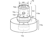
- FIG. 3 is an external perspective view showing an external appearance of a valve body 72.
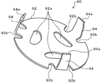
- FIG. 3 is an external perspective view showing an external appearance of a leaf spring 90.
- FIG. It is explanatory drawing which shows a mode that the non-return valve 80 for discharge and the leaf
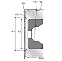
- FIG. FIG. 4 is a front view of the leaf spring 90 side after assembling the discharge check valve 80 and the leaf spring 90 to the piston 60 as viewed from the front, and a cross-sectional view taken along the line AA. It is the elements on larger scale which expanded a part of sectional drawing of FIG.
- FIG. 1 is a block diagram showing an outline of the configuration of an electromagnetic pump 20 as an embodiment of the present invention.
- the electromagnetic pump 20 includes a solenoid unit 30 that generates an electromagnetic force, and a pump unit 40 that operates by the electromagnetic force of the solenoid unit 30.
- the electromagnetic pump 20 includes, for example, an engine and an automatic transmission, stops the engine when an engine stop condition such as a vehicle speed less than a predetermined vehicle speed is satisfied, and stops when the engine start condition is satisfied.
- an engine stop condition such as a vehicle speed less than a predetermined vehicle speed is satisfied
- stops when the engine start condition is satisfied In an automobile with an idling stop function for starting the engine, it is configured as a pump for supplying a predetermined standby pressure to the starting frictional engagement element among the frictional engagement elements included in the automatic transmission when the engine is stopped.
- an electromagnetic coil 32, a plunger 34 as a mover, and a core 36 as a stator are arranged in a solenoid case 31 as a bottomed cylindrical member.
- the solenoid unit 30 forms a magnetic circuit in which a magnetic flux circulates around the solenoid case 31, the plunger 34, and the core 36 by applying a current to the electromagnetic coil 32, and the shaft that is attracted to the plunger 34 and abuts on the tip of the plunger 34.
- the core 36 is formed to have a diameter slightly larger than the diameter of the distal end portion of the plunger 34, and a recess 36a that receives the distal end portion when the plunger 34 is sucked is formed.
- the pump unit 40 is configured as a piston pump that pumps hydraulic oil by reciprocating the piston 60 by the electromagnetic force from the solenoid unit 30 and the biasing force of the coil spring 46, and one end is a solenoid case of the solenoid unit 30.
- a hollow cylindrical cylinder 50 joined to 31, a piston 60 slidably disposed in the cylinder 50, and having a proximal end surface coaxially contacting the distal end of the shaft 38 of the solenoid unit 30;
- a coil spring 46 that urges the piston 60 in a direction opposite to the direction in which the electromagnetic force from the solenoid unit 30 abuts, and the coil spring 46 is supported from the side opposite to the front end surface of the piston 60 and sucked into the pump chamber 56.
- Suction check valve 70 that permits the flow of hydraulic oil in the direction to flow and prohibits the flow in the reverse direction, and check valve 70 for suction
- a strainer 47 that is disposed at the suction port and captures foreign matter such as dust contained in the sucked hydraulic oil, and permits the flow of hydraulic oil in the direction of being discharged from the pump chamber 56 built in the piston 60 and allows the flow in the reverse direction.
- Discharge check valve 80 to be prohibited, and a cylinder cover that covers the other end of the cylinder 50 in a state where the piston 60, the discharge check valve 80, the coil spring 46, and the suction check valve 70 are disposed in the cylinder 50. 48.
- the pump portion 40 is formed such that a suction port 42 is formed at the center of the cylinder cover 48 and a discharge port 44 is formed by cutting out a part in the circumferential direction on the side surface of the cylinder 50.
- the piston 60 has a stepped shape including a cylindrical piston main body 62 and a cylindrical shaft portion 64 having an outer diameter smaller than that of the piston main body 62 and having an end surface in contact with the tip of the shaft 38 of the solenoid portion 30. It is formed and reciprocates in the cylinder 50 in conjunction with the shaft 38 of the solenoid unit 30.
- the piston 60 is formed with a cylindrical bottomed hollow portion 62a at the center of the shaft, and a discharge check valve 80 is disposed in the hollow portion 62a. Further, the hollow portion 62 a extends from the tip end portion of the piston 60 through the inside of the piston main body 62 to the middle of the inside of the shaft portion 64.
- the shaft portion 64 is formed with two through holes 64a and 64b that intersect each other at an angle of 90 degrees in the radial direction.
- a discharge port 44 is formed around the shaft portion 64, and the hollow portion 62a communicates with the discharge port 44 through two through holes 64a and 64b.
- the suction check valve 70 is inserted into the cylinder 50 and has a hollow portion 72a with a bottom formed therein, and a center that connects the hollow portion 72a and the pump chamber 56 at the center of the shaft to the bottom of the hollow portion 72a.
- a valve body 72 having a hole 72b, a ball 74, a coil spring 76 for applying a biasing force to the ball 74, a seat portion for the ball 74, and a center hole 79 having an inner diameter smaller than the outer diameter of the ball 74.
- a plug 78 The intake check valve 70 is assembled by inserting the coil spring 76 and the ball 74 in this order into the hollow portion 72a of the valve body 72 and then press-fitting the plug 78.
- FIG. 2 is an external view showing the external appearance of the valve body 72.
- the valve main body 72 is formed in a stepped shape including a cylindrical pedestal portion 73a and a substantially cylindrical protruding portion 73b protruding from the seating surface of the pedestal portion 73a.
- the pedestal portion 73a supports the coil spring 46 with an annular surface at the peripheral edge of the seat surface, and the height of the seat surface is adjusted to be a spring interval for realizing a necessary urging force.
- the protruding portion 73b is formed so as to protrude into the pump chamber 56, and the protruding height and diameter are adjusted so that the volume in the pump chamber 56 becomes a volume for realizing a necessary discharge pressure.
- the flange protrusion 73b is formed in a stepped shape having a first outer diameter portion O1 and a second outer diameter portion O2 having a smaller diameter than the first outer diameter portion O1 from the pedestal portion 73a side.
- the first outer diameter portion O1 is formed to have an outer diameter slightly smaller than the inner diameter of the coil spring 46, and when the coil spring 46 is fitted, the coil spring 46 is fixed so as not to be displaced in the radial direction.
- the second outer diameter portion O2 is formed in a cylindrical shape having a substantially uniform outer diameter with respect to the axial direction, and two through holes 72c and 72d are formed that intersect each other at an angle of 90 degrees in the radial direction. ing.
- the protrusion 73b has a round (R) formed at the outer peripheral edge portion of the tip (protruding end).
- the protrusion part 73b becomes the valve-axis direction, and the 1st outer diameter part O1 and the 2nd outer diameter part O2 of the outer periphery comprise the side wall of the protrusion part 73b.
- the back side of the protruding end of the protruding portion 73b is the bottom of the hollow portion 72a.
- the hollow portion 72a formed inside the valve main body 72 passes through the inside of the pedestal portion 73a from the back surface of the pedestal portion 73a, and projects so as to communicate with the central hole 72b and the two through holes 72c and 72d. It extends to the vicinity of the protruding end of the portion 73b.
- the hollow portion 72a accommodates a first inner diameter portion I1 in which the ball 74 can move in the axial direction with an inner diameter smaller than the outer diameter of the ball 74, and a coil spring 76 with an inner diameter smaller than the first inner diameter portion I1. And a second inner diameter portion I2.
- the gap between the inner wall surface and the ball 74 forms a hydraulic oil passage
- the clearance between the lines of the spring 76 and the space on the inner peripheral side of the coil spring 76 form an oil passage for the hydraulic oil.
- the check valve 70 for suction is accompanied by contraction of the coil spring 76 when the differential pressure (P1-P2) between the pressure P1 on the input side and the pressure P2 on the output side exceeds a predetermined pressure that overcomes the biasing force of the coil spring 76.
- P1-P2 differential pressure
- the valve is closed by being pressed against the hole 79 and closing the central hole 79.
- the discharge check valve 80 includes a ball 84, a coil spring 86 for applying a biasing force to the ball 84, a plug 88 as an annular member having a center hole 89 having an inner diameter smaller than the outer diameter of the ball 84, Is provided.
- the discharge check valve 80 is assembled by inserting the coil spring 86 and the ball 84 in this order into the hollow portion 62a of the piston 60 and then press-fitting the plug 88.
- the gap between the inner wall surface of the hollow portion 62 a of the piston 62 and the outer peripheral side of the ball 84 and the coil spring 86 forms an oil passage for the hydraulic oil.
- the differential pressure (P2-P3) between the input side pressure (the output side pressure of the suction check valve 70) P2 and the output side pressure P3 overcomes the biasing force of the coil spring 86.
- the ball 84 is released from the central hole 89 of the plug 88 with the contraction of the coil spring 86, and when the differential pressure (P2-P3) is less than the predetermined pressure, the coil spring is opened.
- the ball 84 is pressed against the center hole 89 of the plug 88 along with the extension of 86 to close the center hole 89 to close the valve.
- the leaf spring 90 is attached so as to cover the opening of the hollow portion 62a of the piston 60.
- FIG. 3 is an external perspective view showing the external appearance of the leaf spring 90
- FIG. 4 is an explanatory view showing how the discharge check valve 80 and the leaf spring 90 are assembled to the piston 60.
- the leaf spring 90 is formed of a magnetic metal such as iron, and as shown in FIG. 3, a disk-shaped disk portion 92 in which three communication holes 92 a are formed along the circumferential direction, and an outer portion of the disk portion 92. And three leg portions 94 extending in the orthogonal direction from the periphery.
- the leaf spring 90 is formed by punching a flat plate member to form an outer shape and then bending the three leg portions 94 in the orthogonal direction.
- notched grooves 92b are formed on both sides of the base of the three leg portions 94 so that the flatness in the vicinity of the outer peripheral edge of the disc portion 92 is not impaired when the leg portions 94 are bent. ing.
- the three communicating holes 92a are each formed in a substantially elliptical shape such that the long side is in the circumferential direction and the short side is in the radial direction.
- the disk portion 92 is formed so that the radius of curvature on the outer diameter side is larger (close to a straight line) than the radius of curvature on the inner diameter side.
- the three leg portions 94 are formed with claws 94a bent inward at the tip end portions in order to attach the leaf spring 90 to the piston main body 62.
- the communication holes 92a and the leg portions 94 are arranged at equiangular intervals (120 degree intervals) so as to be aligned in the radial direction (radial direction).
- the leg part 94 is arrange
- the leaf spring 90 of this embodiment when the disk portion 92 is subjected to an impact, stress tends to concentrate on the narrowed portion between the adjacent communication holes 92a, so the strength is relatively weak from this portion. This is to ensure durability by keeping the leg portion 94 away.
- the assembly of the discharge check valve 80 and the leaf spring 90 to the piston 60 is performed by inserting a coil spring 86 and a ball 84 into the hollow portion 62a of the piston body 62 in this order, and press-fitting a plug 88.
- a plate spring 90 is attached to the tip of the piston body 62, and the claw 94a of the leg 94 is engaged with the groove 62b formed in the outer periphery of the piston body 62.
- the outer periphery of the piston body 62 It is done by caulking.
- the discharge check valve 80 and the leaf spring 90 are assembled in advance to the piston 60 in this way, so that they are arranged in the cylinder 50 after they are sub-assembled.
- FIG. 5 is a front view of the leaf spring 90 side after assembling the discharge check valve 80 and the leaf spring 90 to the piston 60 as viewed from the front, and a sectional view showing the AA section.
- FIG. 6 is a partially enlarged view in which a part of the sectional view of FIG. 5 is enlarged.
- the inner peripheral portion of the disk portion 92 forms an elastically deformable region, it functions as an impact absorbing member that absorbs an impact on this region.
- the inner peripheral edge side of the cylindrical end surface 62c is chamfered, and the elastically deformable region (diameter) of the leaf spring 90 is R3 larger than the inner diameter R2 of the hollow portion 62a.
- the outer diameter R1 (see FIG. 2) of the protruding end of the protruding portion 73b described above is smaller than the inner diameter R2.
- the cylindrical end surface 62c of the piston main body 62 is also chamfered on the outer peripheral edge side in order to facilitate mounting of the plate spring 90 to the piston main body 62.
- the soot cylinder 50 forms a pump chamber 56 by a space surrounded by the inner wall 51, the tip end surface (plate spring 90) of the piston 60 and the surface of the suction check valve 70 on the coil spring 46 side.
- the suction check valve 70 is opened and the discharge check valve 80 is opened as the volume in the pump chamber 56 increases. Is closed and sucks the working oil through the suction port 42, and when the piston 60 moves (moves forward) by the electromagnetic force of the solenoid unit 30, the suction check valve for suction is reduced as the volume in the pump chamber 56 decreases.
- the discharge check valve 80 is opened to discharge the sucked hydraulic oil through the discharge port 44.
- an inner wall 52 on which the piston main body 62 slides and an inner wall 54 on which the shaft portion 64 slides are formed with a step, and the discharge port 44 is formed at the step portion.
- the step portion forms a space surrounded by the annular surface of the step portion between the piston main body 62 and the shaft portion 64 and the outer peripheral surface of the shaft portion 64. Since this space is formed on the opposite side of the pump chamber 56 across the piston main body 62, the volume decreases when the volume of the pump chamber 56 increases, and the volume decreases when the volume of the pump chamber 56 decreases. Expanding.
- the volume change of this space is such that the area (pressure receiving area) that receives pressure from the pump chamber 56 side of the piston 60 is larger than the area (pressure receiving area) that receives pressure from the discharge port 44 side. It becomes smaller than the volume change. For this reason, this space functions as the second pump chamber 58. That is, when the piston 60 moves (returns) by the urging force of the coil spring 46, an amount of hydraulic oil corresponding to the enlarged volume of the pump chamber 56 is supplied from the suction port 42 through the suction check valve 70. 56, the amount of hydraulic oil corresponding to the reduced volume of the second pump chamber 58 is discharged from the second pump chamber 58 via the discharge port 44, and the piston 30 is driven by the electromagnetic force of the solenoid unit 30.
- the distance between the distal end portion of the plunger 34 and the concave portion 36a of the core 36 facing the plunger portion L1 is set to L1 in a state where the solenoid portion 30 is stopped.
- L1 the distance between the tip end portion (plate spring 90) of the piston 60 and the protruding end face of the valve body 72 facing the piston L. Therefore, when the piston 60 moves forward as the solenoid unit 30 is driven, the leaf spring 90 collides with the protruding end surface of the valve main body 72, and the plunger 34 does not collide with the core 36.
- the leaf spring 90 has an elastically deformable region having a diameter R3 that is larger than the outer diameter R1 of the protruding end surface of the valve body 72. can do. Since the electromagnetic pump 20 of this embodiment is mounted on a vehicle and driven while the engine is stopped when the vehicle stops, an occupant tends to feel the occurrence of abnormal noise. For this reason, the comfort of the occupant can be further improved by suppressing the occurrence of a collision sound accompanying the driving of the electromagnetic pump 20.
- the leaf spring 90 is attached to the tip portion of the piston 60, and the tip portion of the plunger 34 in the state where the solenoid portion 30 is stopped driving and the core 36 ( Since the distance L1 to the recess 36a) is shorter than the distance L2 between the tip end portion (plate spring 90) of the piston 60 and the projecting end surface of the valve body 72 facing the piston 60, when the solenoid portion 30 is driven,
- the leaf spring 90 can collide with the protruding end surface of the valve body 72 so that the plunger 34 does not collide with the core 36.
- the impact applied to the piston 60 by the elastic force of the leaf spring 90 can be absorbed, the occurrence of collision noise can be effectively suppressed.
- the elastically deformable region of the leaf spring 90 (disk portion 92) can be widened, and the shock absorbing performance can be further improved.
- a magnetic metal such as iron that cannot be used when the elastic member is disposed in the solenoid unit 30 is used as the material of the leaf spring 90. And sufficient durability can be ensured.
- the leg portion 94 is When the leaf spring 90 is formed by being bent, the flatness in the vicinity of the outer peripheral edge of the disk portion 92 can be prevented from being impaired. As a result, the assemblability of the leaf spring 90 can be further improved. Further, since the communication holes 92a and the leg portions 94 of the leaf spring 90 are arranged at equal angular intervals so as to be aligned in the radial direction (radial direction), the leg portions 94 are narrowed between the adjacent communication holes 92a. It can be kept away from the site.
- the electromagnetic pump 20 Assembling property can be further improved.
- the elastic member (the leaf spring 90) is provided on the piston 60 side, but the invention is not limited to this, and the elastic member (plate spring 90) may be provided on the valve body 72 side that supports the coil spring 46. Alternatively, depending on the configuration of the elastic member, it may be provided on both the piston 60 side and the valve body 72 side.
- the three leg portions 94 are formed on the outer peripheral edge of the disk portion 92 as the leaf spring 90.
- the present invention is not limited to this, and the number of leg portions is four. Any number of legs may be used as long as the number of legs is plural, such as six. However, if the number of the leg portions 94 is three, it is possible to ensure stability when the leaf spring 90 is fixed to the piston 60 while reducing the number of leg portions 94.
- the leaf spring 90 is formed with the cutout portions 92b on both sides of the base of the leg portion 94.
- the present invention is not limited to this, and the cutout portion 92b is not formed. It is good.
- the three spring holes 92a are formed in the disk portion 92 as the leaf spring 90.
- the present invention is not limited to this, and the number of the communication holes may be any number. Absent.
- the number of communication holes may be one, or two or more than four. Alternatively, a large number of pores may be formed in the disk portion 92.
- the shape of the communication hole 92a formed in the disk portion 92 of the leaf spring 90 is substantially elliptical, but the shape is not limited to this, and may be any shape, for example, circular. Also good.
- the impact due to the collision between the valve main body 72 and the piston 60 is absorbed by the leaf spring 90, but the invention is not limited to this.
- other elastic members such as rubber are used. It may be used.
- a magnetic metal such as iron in order to ensure the durability of the member.
- the suction check valve 70 and the leaf spring 90 are attached to the piston 60 in advance to form a sub-assembly and then assembled into the cylinder 50. However, they may be assembled separately. Absent.
- the discharge check valve 70 is built in the piston 60, but the discharge check valve 80 is not built in the piston 60, for example, built in a valve body outside the cylinder 50. It does not matter.
- the electromagnetic pump 20 of the embodiment is configured as an electromagnetic pump of a type that discharges hydraulic oil twice from the discharge port 44 by one reciprocating motion of the piston 60.
- the present invention is not limited to this.
- the hydraulic oil When the piston is moved forward by electromagnetic force from the part, the hydraulic oil is sucked into the pump chamber from the suction port, and when the piston is moved backward by the biasing force of the coil spring, the hydraulic oil in the pump chamber is discharged from the discharge port.
- the piston is moved backward by the biasing force of the coil spring, the hydraulic oil is sucked into the pump chamber from the suction port, and the hydraulic oil in the pump chamber is discharged from the discharge port when the piston is moved forward by the electromagnetic force from the solenoid section.
- Any type of electrical equipment can be used as long as it can discharge the working fluid as the piston reciprocates. It may be used as the pump.
- the electromagnetic pump 20 of the embodiment is used for a hydraulic control device for hydraulically driving clutches and brakes of an automatic transmission mounted on an automobile.
- the invention is not limited to this.
- fuel is transferred or lubricated.
- the present invention may be applied to any system such as transferring a liquid for use.
- the piston 60 corresponds to the “piston”
- the solenoid portion 30 corresponds to the “electromagnetic portion”
- the coil spring 46 corresponds to the “spring”
- the valve main body 72 of the suction check valve 70 is “supported”.
- the plate spring 90 corresponds to an “elastic member”.
- the pedestal portion 73a corresponds to a “support portion”
- the protruding portion 73b corresponds to a “projecting portion”.
- the present invention can be used in the manufacturing industry of electromagnetic pumps.
Landscapes
- Engineering & Computer Science (AREA)
- Mechanical Engineering (AREA)
- General Engineering & Computer Science (AREA)
- Electromagnetic Pumps, Or The Like (AREA)
- Details Of Reciprocating Pumps (AREA)
Abstract
Description
ピストンを往復動させることにより作動流体の吸入と吐出とを行なう電磁ポンプであって、
電磁力によってプランジャをコアに吸引させることにより前記ピストンの基端部に推力を付与して前記ピストンを往動させる電磁部と、
前記ピストンの先端部に付勢力を付与して前記ピストンを復動させるスプリングと、
前記スプリングを支持すると共に、前記ピストンの先端部と対向する特定部を有する支持部材と、
前記ピストンの先端部および前記支持部材の特定部のうち少なくとも一方に設けられた弾性部材と、
を備え、
前記電磁部を駆動して前記ピストンを往動させたときに該ピストンの先端部が前記弾性
部材を介して前記支持部材の特定部と衝突するように、前記電磁部を停止しているときの前記支持部材の特定部と前記ピストンの先端部との距離を前記プランジャと前記コアとの距離よりも短くする
ことを要旨とする。
要素との対応関係について説明する。実施例では、ピストン60が「ピストン」に相当し、ソレノイド部30が「電磁部」に相当し、コイルスプリング46が「スプリング」に相当し、吸入用逆止弁70の弁本体72が「支持部材」に相当し、板バネ90が「弾性部材」に相当する。また、台座部73aが「支持部」に相当し、突出部73bが「突出部」に相当する。なお、実施例の主要な要素と発明の概要の欄に記載した発明の主要な要素との対応関係は、実施例が発明の概要の欄に記載した発明を実施するための最良の形態を具体的に説明するための一例であることから、発明の概要の欄に記載した発明の要素を限定するものではない。即ち、発明の概要の欄に記載した発明についての解釈はその欄の記載に基づいて行なわれるべきものであり、実施例は発明の概要の欄に記載した発明の具体的な一例に過ぎないものである。
Claims (11)
- ピストンを往復動させることにより作動流体の吸入と吐出とを行なう電磁ポンプであって、
電磁力によってプランジャをコアに吸引させることにより前記ピストンの基端部に推力を付与して前記ピストンを往動させる電磁部と、
前記ピストンの先端部に付勢力を付与して前記ピストンを復動させるスプリングと、
前記スプリングを支持すると共に、前記ピストンの先端部と対向する特定部を有する支持部材と、
前記ピストンの先端部および前記支持部材の特定部のうち少なくとも一方に設けられた弾性部材と、
を備え、
前記電磁部を駆動して前記ピストンを往動させたときに該ピストンの先端部が前記弾性部材を介して前記支持部材の特定部と衝突するように、前記電磁部を停止しているときの前記支持部材の特定部と前記ピストンの先端部との距離を前記プランジャと前記コアとの距離よりも短くする
ことを特徴とする電磁ポンプ。 - 請求項1記載の電磁ポンプであって、
前記支持部材は、前記スプリングを支持する支持部と、該支持部よりも前記ピストンの先端部側に突出した突出部とが形成され、
前記特定部は、前記突出部の突出端面である
ことを特徴とする電磁ポンプ。 - 請求項1または2記載の電磁ポンプであって、
前記スプリングは、コイルスプリングであり、
前記ピストンの先端部は、環状の円筒端面で前記コイルスプリングの付勢力を受ける円筒部として形成され、
前記弾性部材は、前記円筒部の開口を覆うように取り付けられた板バネであり、
前記支持部材の特定部は、その外径が前記円筒部の内径よりも小さくなるよう形成されてなる
ことを特徴とする電磁ポンプ。 - 請求項3記載の電磁ポンプであって、
前記ピストンの円筒部は、円筒端面の内周縁が面取りされてなる
ことを特徴とする電磁ポンプ。 - 請求項3または4記載の電磁ポンプであって、
前記板バネは、前記円筒部の開口を覆う円盤部と、該円盤部の外周縁から前記円筒部の軸方向に沿って延伸された複数の脚部とを備える
ことを特徴とする電磁ポンプ。 - 請求項5記載の電磁ポンプであって、
前記板バネは、前記円盤部と前記脚部とが一体形成されており、前記脚部の付け根の両側に切り欠き部が形成されてなる
ことを特徴とする電磁ポンプ。 - 前記ピストンを往復動させることにより作動流体を吸入用逆止弁を介して吸入すると共に該吸入した作動流体を吐出用逆止弁を介して吐出する請求項5または6記載の電磁ポンプであって、
前記吐出用逆止弁は、前記ピストンの円筒部に内蔵され、
前記板バネは、前記支持部材の特定部に衝突させる衝突面に作動流体を前記吐出用逆止弁へ流入させる複数の連通孔が形成されてなる
ことを特徴とする電磁ポンプ。 - 請求項7記載の電磁ポンプであって、
前記連通孔は、前記円盤部に対して長辺が周方向に短辺が径方向となるよう略楕円形状に形成されてなる
ことを特徴とする電磁ポンプ。 - 請求項7または8記載の電磁ポンプであって、
前記連通孔は、等角度間隔で周方向に3つ形成されてなる
ことを特徴とする電磁ポンプ。 - 請求項7ないし9いずれか1項に記載の電磁ポンプであって、
前記連通孔と前記脚部は、それぞれ等角度間隔で周方向に同数形成されると共に、対応する前記連通孔と前記脚部とが半径方向に並ぶように形成されてなる
ことを特徴とする電磁ポンプ。 - 請求項7ないし10いずれか1項に記載の電磁ポンプであって、
前記吸入用逆止弁は、前記支持部材に内蔵され、
前記吸入用逆止弁と前記吐出用逆止弁は、前記ピストンの往復動軸に対して同軸上に配置されてなる
ことを特徴とする電磁ポンプ。
Priority Applications (3)
| Application Number | Priority Date | Filing Date | Title |
|---|---|---|---|
| US14/431,833 US9957957B2 (en) | 2012-10-31 | 2013-10-29 | Electromagnetic pump |
| DE112013004084.0T DE112013004084B4 (de) | 2012-10-31 | 2013-10-29 | Elektromagnetische Pumpe mit einem elastischen Element am Kolben |
| CN201380048978.9A CN104662297B (zh) | 2012-10-31 | 2013-10-29 | 电磁泵 |
Applications Claiming Priority (2)
| Application Number | Priority Date | Filing Date | Title |
|---|---|---|---|
| JP2012240573A JP5949455B2 (ja) | 2012-10-31 | 2012-10-31 | 電磁ポンプ |
| JP2012-240573 | 2012-10-31 |
Publications (1)
| Publication Number | Publication Date |
|---|---|
| WO2014069455A1 true WO2014069455A1 (ja) | 2014-05-08 |
Family
ID=50627358
Family Applications (1)
| Application Number | Title | Priority Date | Filing Date |
|---|---|---|---|
| PCT/JP2013/079260 Ceased WO2014069455A1 (ja) | 2012-10-31 | 2013-10-29 | 電磁ポンプ |
Country Status (5)
| Country | Link |
|---|---|
| US (1) | US9957957B2 (ja) |
| JP (1) | JP5949455B2 (ja) |
| CN (1) | CN104662297B (ja) |
| DE (1) | DE112013004084B4 (ja) |
| WO (1) | WO2014069455A1 (ja) |
Cited By (1)
| Publication number | Priority date | Publication date | Assignee | Title |
|---|---|---|---|---|
| JP2017067038A (ja) * | 2015-10-01 | 2017-04-06 | トヨタ自動車株式会社 | 燃料ポンプ |
Families Citing this family (5)
| Publication number | Priority date | Publication date | Assignee | Title |
|---|---|---|---|---|
| KR101915501B1 (ko) * | 2016-07-25 | 2018-11-08 | 이래에이엠에스 주식회사 | 차량의 브레이크 시스템용 피스톤 펌프 |
| WO2019054510A1 (ja) * | 2017-09-15 | 2019-03-21 | アイシン・エィ・ダブリュ株式会社 | 油圧ポンプ |
| CN114837792A (zh) | 2021-03-10 | 2022-08-02 | 美普盛(上海)汽车零部件有限公司 | 一种带膨胀补偿密封件的电动冷却液泵 |
| US12247556B2 (en) * | 2022-06-14 | 2025-03-11 | Hydac Fluidtechnik Gmbh | Pump device |
| CN115479025B (zh) * | 2022-10-04 | 2025-03-14 | 贵州航天控制技术有限公司 | 液压变量柱塞泵及电液伺服系统 |
Citations (4)
| Publication number | Priority date | Publication date | Assignee | Title |
|---|---|---|---|---|
| JPH11117858A (ja) * | 1997-10-09 | 1999-04-27 | Nippon Control Kogyo Kk | 電磁ポンプ |
| JP2005240599A (ja) * | 2004-02-25 | 2005-09-08 | Mikuni Corp | プランジャ式流体吐出装置 |
| JP2011021593A (ja) * | 2009-06-18 | 2011-02-03 | Aisin Aw Co Ltd | 電磁ポンプ |
| JP2011252491A (ja) * | 2010-05-06 | 2011-12-15 | Nachi Fujikoshi Corp | 電磁ポンプ |
Family Cites Families (15)
| Publication number | Priority date | Publication date | Assignee | Title |
|---|---|---|---|---|
| US4047852A (en) * | 1976-08-16 | 1977-09-13 | Walbro Corporation | In-line pump construction |
| DE3504789A1 (de) * | 1985-02-13 | 1986-08-14 | Webasto-Werk W. Baier GmbH & Co, 8035 Gauting | Elektromagnetisch betaetigte kolbenpumpe |
| GB8708417D0 (en) | 1987-04-08 | 1987-05-13 | Eaton Sa Monaco | Electric pump |
| GB2265106B (en) * | 1992-03-18 | 1995-07-05 | Max Co Ltd | Air-pressure-operated impulsion mechanism |
| DE9312752U1 (de) | 1993-08-26 | 1993-12-23 | Thomas Magnete Gmbh, 57562 Herdorf | Elektromagnetisch betreibbare Pumpe, insbesondere Dosierpumpe |
| DE19925250A1 (de) * | 1999-06-01 | 2000-12-07 | Continental Teves Ag & Co Ohg | Kolbenpumpe |
| CN2883723Y (zh) * | 2006-01-17 | 2007-03-28 | 深圳宗泰电子有限公司 | 电磁微量泵 |
| JP4710636B2 (ja) * | 2006-02-07 | 2011-06-29 | 株式会社アドヴィックス | フィルタを用いたピストンポンプ及びバルブシート部材へのフィルタ組み付け方法 |
| DE102007031033A1 (de) | 2007-07-04 | 2007-10-31 | J. Eberspächer GmbH & Co. KG | Rückschlagventileinsatz für eine Brennstoffdosierpumpe |
| DE102008013440A1 (de) | 2008-03-10 | 2009-09-17 | Thomas Magnete Gmbh | Magnetbetätigte Hubkolbenpumpe mit hydraulischer Dämpfung |
| JP5093090B2 (ja) * | 2008-12-25 | 2012-12-05 | アイシン・エィ・ダブリュ株式会社 | 電磁弁装置および動力伝達装置 |
| DE102010013106A1 (de) | 2010-03-26 | 2011-09-29 | Thomas Magnete Gmbh | Pumpe |
| JP5538090B2 (ja) * | 2010-06-23 | 2014-07-02 | 株式会社ジャパンディスプレイ | ガラスカッター |
| JP5505347B2 (ja) | 2011-03-25 | 2014-05-28 | アイシン・エィ・ダブリュ株式会社 | 電磁ポンプ |
| JP5505346B2 (ja) * | 2011-03-25 | 2014-05-28 | アイシン・エィ・ダブリュ株式会社 | 電磁ポンプ |
-
2012
- 2012-10-31 JP JP2012240573A patent/JP5949455B2/ja active Active
-
2013
- 2013-10-29 WO PCT/JP2013/079260 patent/WO2014069455A1/ja not_active Ceased
- 2013-10-29 US US14/431,833 patent/US9957957B2/en active Active
- 2013-10-29 DE DE112013004084.0T patent/DE112013004084B4/de active Active
- 2013-10-29 CN CN201380048978.9A patent/CN104662297B/zh active Active
Patent Citations (4)
| Publication number | Priority date | Publication date | Assignee | Title |
|---|---|---|---|---|
| JPH11117858A (ja) * | 1997-10-09 | 1999-04-27 | Nippon Control Kogyo Kk | 電磁ポンプ |
| JP2005240599A (ja) * | 2004-02-25 | 2005-09-08 | Mikuni Corp | プランジャ式流体吐出装置 |
| JP2011021593A (ja) * | 2009-06-18 | 2011-02-03 | Aisin Aw Co Ltd | 電磁ポンプ |
| JP2011252491A (ja) * | 2010-05-06 | 2011-12-15 | Nachi Fujikoshi Corp | 電磁ポンプ |
Cited By (2)
| Publication number | Priority date | Publication date | Assignee | Title |
|---|---|---|---|---|
| JP2017067038A (ja) * | 2015-10-01 | 2017-04-06 | トヨタ自動車株式会社 | 燃料ポンプ |
| US10066613B2 (en) | 2015-10-01 | 2018-09-04 | Toyota Jidosha Kabushiki Kaisha | Fuel pump |
Also Published As
| Publication number | Publication date |
|---|---|
| US9957957B2 (en) | 2018-05-01 |
| JP5949455B2 (ja) | 2016-07-06 |
| DE112013004084T5 (de) | 2015-05-07 |
| DE112013004084B4 (de) | 2016-09-15 |
| CN104662297A (zh) | 2015-05-27 |
| US20150260172A1 (en) | 2015-09-17 |
| CN104662297B (zh) | 2016-09-14 |
| JP2014088856A (ja) | 2014-05-15 |
Similar Documents
| Publication | Publication Date | Title |
|---|---|---|
| JP5949455B2 (ja) | 電磁ポンプ | |
| JP5803776B2 (ja) | 電磁ポンプ | |
| JP5136533B2 (ja) | 電磁ポンプ | |
| CN109215932B (zh) | 燃料泵螺线管组件和方法 | |
| JP5120419B2 (ja) | 常閉型電磁弁 | |
| US9017044B2 (en) | Electromagnetic pump | |
| US20140119964A1 (en) | Electromagnetic pump device | |
| JP5494802B2 (ja) | 容量可変型圧縮機 | |
| JP5677574B2 (ja) | 閉止体を備えるピストンポンプのバルブ | |
| JP5510415B2 (ja) | 電磁ポンプ | |
| JP2007278218A (ja) | 燃料噴射弁 | |
| JP5630406B2 (ja) | 電磁ポンプ | |
| JP2012202340A (ja) | 電磁ポンプ | |
| JP2016070222A (ja) | 電磁ポンプ | |
| JP4572809B2 (ja) | 電磁制御弁および電磁制御弁の組付け方法 | |
| US20210041899A1 (en) | Valve device | |
| WO2012132668A1 (ja) | 電磁ポンプ | |
| CN220134167U (zh) | 一种内循环泄压式柱塞泵及包含其的油泵 | |
| JP2006183754A (ja) | 電磁弁 | |
| JP5579686B2 (ja) | プランジャポンプ | |
| JP2007255502A (ja) | ソレノイド及び電磁弁 | |
| JP2005076871A (ja) | 電磁アクチュエータ | |
| JP2008240529A (ja) | ポンプ装置 | |
| JP2006038103A (ja) | オイルコントロールバルブ | |
| JP2015081559A (ja) | 電動ポンプ |
Legal Events
| Date | Code | Title | Description |
|---|---|---|---|
| 121 | Ep: the epo has been informed by wipo that ep was designated in this application |
Ref document number: 13851073 Country of ref document: EP Kind code of ref document: A1 |
|
| WWE | Wipo information: entry into national phase |
Ref document number: 1120130040840 Country of ref document: DE Ref document number: 112013004084 Country of ref document: DE |
|
| WWE | Wipo information: entry into national phase |
Ref document number: 14431833 Country of ref document: US |
|
| 122 | Ep: pct application non-entry in european phase |
Ref document number: 13851073 Country of ref document: EP Kind code of ref document: A1 |