WO2014050154A1 - ロータおよび回転電気機械 - Google Patents
ロータおよび回転電気機械 Download PDFInfo
- Publication number
- WO2014050154A1 WO2014050154A1 PCT/JP2013/005829 JP2013005829W WO2014050154A1 WO 2014050154 A1 WO2014050154 A1 WO 2014050154A1 JP 2013005829 W JP2013005829 W JP 2013005829W WO 2014050154 A1 WO2014050154 A1 WO 2014050154A1
- Authority
- WO
- WIPO (PCT)
- Prior art keywords
- magnet
- permanent magnet
- rotor
- rotor core
- permanent
- Prior art date
Links
Images


Classifications
-
- H—ELECTRICITY
- H02—GENERATION; CONVERSION OR DISTRIBUTION OF ELECTRIC POWER
- H02K—DYNAMO-ELECTRIC MACHINES
- H02K1/00—Details of the magnetic circuit
- H02K1/06—Details of the magnetic circuit characterised by the shape, form or construction
- H02K1/22—Rotating parts of the magnetic circuit
- H02K1/27—Rotor cores with permanent magnets
- H02K1/2706—Inner rotors
- H02K1/272—Inner rotors the magnetisation axis of the magnets being perpendicular to the rotor axis
- H02K1/274—Inner rotors the magnetisation axis of the magnets being perpendicular to the rotor axis the rotor consisting of two or more circumferentially positioned magnets
- H02K1/2753—Inner rotors the magnetisation axis of the magnets being perpendicular to the rotor axis the rotor consisting of two or more circumferentially positioned magnets the rotor consisting of magnets or groups of magnets arranged with alternating polarity
- H02K1/276—Magnets embedded in the magnetic core, e.g. interior permanent magnets [IPM]
- H02K1/2766—Magnets embedded in the magnetic core, e.g. interior permanent magnets [IPM] having a flux concentration effect
- H02K1/2773—Magnets embedded in the magnetic core, e.g. interior permanent magnets [IPM] having a flux concentration effect consisting of tangentially magnetized radial magnets
-
- H—ELECTRICITY
- H02—GENERATION; CONVERSION OR DISTRIBUTION OF ELECTRIC POWER
- H02K—DYNAMO-ELECTRIC MACHINES
- H02K1/00—Details of the magnetic circuit
- H02K1/06—Details of the magnetic circuit characterised by the shape, form or construction
- H02K1/22—Rotating parts of the magnetic circuit
- H02K1/27—Rotor cores with permanent magnets
- H02K1/2706—Inner rotors
- H02K1/272—Inner rotors the magnetisation axis of the magnets being perpendicular to the rotor axis
- H02K1/274—Inner rotors the magnetisation axis of the magnets being perpendicular to the rotor axis the rotor consisting of two or more circumferentially positioned magnets
- H02K1/2753—Inner rotors the magnetisation axis of the magnets being perpendicular to the rotor axis the rotor consisting of two or more circumferentially positioned magnets the rotor consisting of magnets or groups of magnets arranged with alternating polarity
- H02K1/276—Magnets embedded in the magnetic core, e.g. interior permanent magnets [IPM]
- H02K1/2766—Magnets embedded in the magnetic core, e.g. interior permanent magnets [IPM] having a flux concentration effect
-
- H—ELECTRICITY
- H02—GENERATION; CONVERSION OR DISTRIBUTION OF ELECTRIC POWER
- H02K—DYNAMO-ELECTRIC MACHINES
- H02K2213/00—Specific aspects, not otherwise provided for and not covered by codes H02K2201/00 - H02K2211/00
- H02K2213/03—Machines characterised by numerical values, ranges, mathematical expressions or similar information
Definitions
- This invention relates to a rotor and a rotating electric machine, and more particularly to a rotor structure.
- Patent Document 1 rotating electric machines such as electric motors and generators have been used (for example, Patent Document 1). Further, in such a rotating electric machine, it is known that the magnetic flux of the permanent magnet is increased by increasing the surface area of the permanent magnet embedded in the rotor (more specifically, the area of the outer peripheral surface of the permanent magnet). It has been. In particular, when the permanent magnet is composed of a bonded magnet, the residual magnetic flux density of the bonded magnet is lower than that of the rare earth sintered magnet. Therefore, it is effective to increase the permanent magnet surface area by increasing the surface area of the permanent magnet. is there.
- an object of the present invention is to provide a rotor capable of suppressing a decrease in the amount of flux linkage of a permanent magnet.
- a first invention includes a rotor core (110) and a plurality of permanent magnets (100) embedded in the rotor core (110), and the permanent magnet (100) crosses the radial direction of the rotor core (110).
- the magnet body portion (101) formed in this way, and it bends to the outer peripheral surface side of the magnet body portion (101) and extends from both ends in the circumferential direction of the magnet body portion (101) toward the outer edge of the rotor core (110).
- a pair of magnet ends (102), and the magnetization direction (D2) of the magnet end (102) of the permanent magnet (100) is the outer peripheral side of the magnet body (101) of the permanent magnet (100)
- the direction of magnetization of the magnet end (102) of the permanent magnet (100) relative to the magnetic pole center line (PC) of the permanent magnet (100) (D2) ) Of the permanent magnet (100) with respect to the magnetic pole center line (PC) of the permanent magnet (100). ) Is larger than the inclination angle ( ⁇ 1) of the magnetization direction (D1).
- the magnetic flux at the magnet end (102) of the permanent magnet (100) is applied to the magnetic pole center line (PC) of the permanent magnet (100) on the outer peripheral side of the magnet main body (101). Therefore, leakage flux of the permanent magnet (100) (more specifically, leakage flux from the permanent magnet (100) to the adjacent teeth) can be reduced.
- a second invention is the rotor according to the first invention, wherein the permanent magnet (100) is constituted by a bonded magnet.
- the permanent magnet (100) can be formed by injection molding using a molten resin containing magnet powder.
- the extension width (W) of the magnet end (102) of the permanent magnet (100) is equal to the extension length of the magnet end (102) of the permanent magnet (100).
- the rotor is shorter than the length (L).
- the magnetic resistance in the width direction of the magnet end (102) can be made lower than the magnetic resistance in the length direction of the magnet end (102). It becomes easy to magnetize the magnet end (102) so that the magnetization direction (D2) intersects the length direction of the magnet end (102).
- the magnet body (101) of the permanent magnet (100) is formed so as to bend toward the outer edge of the rotor core (110), A pair of magnet end portions (102) of the permanent magnet (100) are continuously directed from both circumferential ends of the magnet body portion (101) of the permanent magnet (100) toward the outer edge of the rotor core (110).
- the rotor is formed so as to extend.
- the magnet body (101) is bent convexly toward the outer edge of the rotor core (110), so that the gap between the outer peripheral surface of the magnet body (101) and the outer edge of the rotor core (110) is increased.
- the facing distance can be reduced.
- magnetic saturation can be easily generated in the portion between the outer peripheral surface of the permanent magnet (100) and the outer edge of the rotor core (110) (that is, the outer peripheral portion of the rotor core (110)).
- D-axis inductance can be reduced.
- the magnet body (101) is bent convexly toward the outer edge of the rotor core (110) and the magnet end (102) is bent toward the outer edge of the rotor core (110).
- the area of the outer peripheral surface (that is, the magnetic pole surface) of the permanent magnet (100) can be increased as compared with the case where the magnet body (101) is formed in a straight line. Thereby, the amount of flux linkage of permanent magnet (100) can be increased.
- the magnet main body (101) and the pair of magnet end portions (102) are integrally formed, so that the gap between the magnet main body portion (101) and the magnet end portion (102) is obtained. Generation of leakage magnetic flux can be suppressed. Thereby, the amount of flux linkage of permanent magnet (100) can be increased.
- the d-axis inductance of the rotor (11) can be decreased and the amount of flux linkage of the permanent magnet (100) can be increased.
- Ratio ( ⁇ a / Ld) can be increased.
- the minimum radial distance (L2) from the outer peripheral surface of the magnet body (101) of the permanent magnet (100) to the outer edge of the rotor core (110) is the permanent magnet. It is shorter than the radial distance (L1) from the connection point (P) between the magnet body (101) and the magnet end (102) of the magnet (100) to the outer edge of the rotor core (110). It is a rotor.
- the outer peripheral surface of the magnet body (101) can be brought close to the outer edge of the rotor core (110). Thereby, the opposing distance between the outer peripheral surface of a magnet main-body part (101) and the outer edge of a rotor core (110) can be shortened further.
- the radial distance (L3) from the tip of the magnet end (102) of the permanent magnet (100) to the outer edge of the rotor core (110) is The rotor is characterized by being shorter than the minimum radial distance (L2) from the outer peripheral surface of the magnet body (101) of the permanent magnet (100) to the outer edge of the rotor core (110).
- the tip of the magnet end (102) can be brought close to the outer edge of the rotor core (110). Thereby, generation
- the magnet end (102) of the permanent magnet (100) extends in the radial direction of the rotor core (110). This is a featured rotor.
- the magnetic flux at the magnet end (102) can be used effectively. That is, while facilitating the flow of magnetic flux between the magnet end (102) of the permanent magnet (100) and the opposing tooth portion (tooth portion (212) facing the permanent magnet (100)) of the stator (12), The flow of magnetic flux between the magnet end portion (102) of the permanent magnet (100) and the adjacent tooth portion (another tooth portion (212) adjacent to the opposing tooth portion) of the stator (12) can be suppressed.
- the permanent magnet (100) is formed symmetrically with respect to a magnetic pole center line (PC) of the permanent magnet (100). It is a rotor characterized by having.
- the symmetry of the magnetic flux distribution in the permanent magnet (100) can be ensured.
- a rotary electric machine comprising the rotor (11) of any one of the first to eighth aspects of the invention and a stator (12) through which the rotor (11) is inserted. It is a machine.
- the leakage magnetic flux of the permanent magnet (100) can be reduced, it is possible to suppress a decrease in the amount of interlinkage magnetic flux of the permanent magnet (100).
- the permanent magnet (100) can be formed by injection molding using a molten resin containing magnet powder, the permanent magnet (100) can be formed by using a sintered magnet.
- the permanent magnet (100) can be easily embedded in the rotor core (110).
- the magnet end (102) it is easy to magnetize the magnet end (102) such that the magnetization direction (D2) of the magnet end (102) intersects the length direction of the magnet end (102). Therefore, the magnetization direction (D2) of the magnet end (102) intersects the magnetic pole center line (PC) on the outer peripheral side of the magnet main body (101), and the inclination angle (D2) of the magnet end (102) (
- the permanent magnet (100) can be easily magnetized so that ( ⁇ 2) is larger than the inclination angle ( ⁇ 1) of the magnetization direction (D1) of the magnet body (101).
- the ratio ( ⁇ a / Ld) of the flux linkage to the d-axis inductance can be increased, the current limitation in the rotation control (particularly the weakening magnetic flux control) can be relaxed.
- the facing distance between the outer peripheral surface of the magnet body (101) and the outer edge of the rotor core (110) can be further shortened, the d-axis inductance of the rotor core (110) is further reduced. Can be made.
- the amount of flux linkage of the permanent magnet (100) can be further increased.
- the amount of flux linkage of the permanent magnet (100) can be further increased.
- the symmetry of the magnetic flux distribution in the permanent magnet (100) can be ensured, so that torque ripple generated when the rotor (11) is driven to rotate can be suppressed.
- the ninth aspect since it is possible to suppress a decrease in the amount of flux linkage of the permanent magnet (100) in the rotor (11), it is possible to suppress a decrease in the operating efficiency of the rotating electric machine (10). .
- FIG. 9 is a partial cross-sectional view for explaining in detail the structure of the rotor shown in FIG. 8.
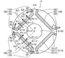
- [Rotating electrical machine] 1 and 2 show a transverse section and a longitudinal section of a rotating electric machine (10) according to an embodiment, respectively.
- the rotary electric machine (10) is used as an electric motor for driving a compressor (not shown) of an air conditioner.
- the rotary electric machine (10) constitutes an embedded magnet type motor (IPM motor).
- the rotating electric machine (10) includes a rotor (11) and a stator (12), and is accommodated in a casing (30) (for example, a casing of a compressor).
- the rotor (11) is fixed to the drive shaft (20).
- axial direction refers to the direction of the axis of the drive shaft (20) (that is, the rotation center (0) of the rotor (11)), and “radial direction” refers to the drive shaft. This is a direction perpendicular to the axial direction of (20), and the “circumferential direction” is a direction around the axis of the drive shaft (20).
- the “outer peripheral side” is a side farther from the axis of the drive shaft (20), and the “inner peripheral side” is a side closer to the axis of the drive shaft (20).
- the “longitudinal section” is a section along the axial direction, and the “transverse section” is a section orthogonal to the axial direction.
- the rotor (11) is rotatably inserted into the stator (12).
- the rotor (11) is formed in a columnar shape
- the stator (12) is formed in a cylindrical shape.
- the stator (12) includes a stator core (201) and a coil (202). In FIG. 1, the hatching of the stator core (201) is not shown.
- the stator core (201) is formed in a cylindrical shape.
- the stator core (201) includes a back yoke part (211), a plurality (six in this example) of tooth parts (212, 212,...), And a plurality (six in this example) of brim parts. (213, 213, ).
- the stator core (201) may be configured by punching an electromagnetic steel sheet by press working to produce a plurality of laminated plates (annular flat plates) and laminating the plurality of laminated plates in the axial direction.
- the back yoke portion (211) is a portion that is an outer peripheral portion of the stator core (201), and is formed in a cylindrical shape.
- the outer periphery of the back yoke portion (211) is fixed to the inner surface of the casing (30).
- Each of the teeth portions (212, 212,%) Is formed in a rectangular parallelepiped shape extending in the radial direction from the inner peripheral surface of the back yoke portion (211).
- the teeth portions (212, 212,%) are arranged in the circumferential direction at predetermined intervals, and coil slots (S200, S200,%) In which the coils (202) are accommodated are disposed between the teeth portions (212, 212,). ) Is formed.
- the brim portion (213, 213,%) Is continuously formed on the inner peripheral side of the tooth portion (212, 212, etc,).
- the brim portion (213) is formed such that its width (length in the circumferential direction) is longer than the width of the teeth portion (212), and its inner circumferential surface is formed in a cylindrical surface shape.
- the inner peripheral surface (cylindrical surface) of the collar portion (213) faces the outer peripheral surface (cylindrical surface) of the rotor (11) with a predetermined distance (air gap (G)).
- the coil (202) is wound around the teeth (212, 212,%) By a concentrated winding method. That is, the coil (202) is wound for each tooth portion (212), and the wound coil (202) is accommodated in the coil slot (S200). Thereby, an electromagnet is formed in each of the tooth portions (212, 212,).
- the rotor (11) has a rotor core (110) and a plurality (four in this example) of permanent magnets (100, 100, etc. 1 and 3, the hatching of the rotor core (110) is not shown.
- the rotor core (110) is formed in a cylindrical shape.
- the rotor core (110) may be configured by punching an electromagnetic steel plate by press working to produce a plurality of laminated plates (circular flat plates) and laminating the plurality of laminated plates in the axial direction.
- a shaft hole (S120) is formed at the center of the rotor core (110).
- the drive shaft (20) is fixed to the shaft hole (S120) by press fitting or the like.
- the rotor core (110) is formed with a plurality (four in this example) of magnet slots (S110, S110,%) For accommodating a plurality of permanent magnets (100, 100, etc, Respectively.
- the magnet slots (S110, S110,%) are arranged at a predetermined pitch (90 ° pitch in this example) in the circumferential direction of the rotor core (110) (that is, around the rotation center (O) of the rotor (11)). Yes.
- the magnet slots (S110, S110,%) Penetrate the rotor core (110) in the axial direction.
- Each of the magnet slots (S110, S110,%) Has a slot body (S111) and a pair of slot ends (S112, S112).
- the slot body (S111) is formed so as to cross the radial direction of the rotor core (110).
- the slot body (S111) is formed so as to be symmetric with respect to the magnetic pole center line (PC) of the permanent magnet (100) accommodated in the magnet slot (S110). That is, the slot body (S111) extends symmetrically about the magnetic pole center line (PC) of the permanent magnet (100) accommodated in the magnet slot (S110).
- the slot body (S111) is formed in a straight line perpendicular to the magnetic pole center line (PC).
- the pair of slot ends (S112, S112) are bent toward the outer peripheral surface (outer peripheral wall surface) of the slot main body (S111), and from both ends in the circumferential direction of the slot main body (S111) to the outer edge of the rotor core (110). It extends toward. That is, the pair of slot end portions (S112, S112) are arranged so that the magnetic pole center line (100) of the permanent magnet (100) housed in the magnet slot (S110) with respect to the extension line at both ends in the circumferential direction of the slot body portion (S111). It extends from the circumferential ends of the slot body (S111) toward the outer edge of the rotor core (110) while being inclined toward the PC) side.
- the slot end (S112) extends linearly from the end of the slot body (S111) toward the outer edge of the rotor core (110).
- the pair of slot end portions (S112, S112) continuously extend from both ends in the circumferential direction of the slot main body portion (S111). That is, the pair of slot end portions (S112, S112) is formed integrally with the slot body portion (S111).
- the permanent magnets (100, 100,%) are accommodated in the magnet slots (S110, S110,%) Of the rotor core (110), respectively. That is, the permanent magnets (100, 100,%) Are arranged at a predetermined pitch (90 ° pitch in this example) in the circumferential direction of the rotor core (110) (that is, around the rotation center (O) of the rotor (11)). ) And buried.
- the permanent magnet (100) is configured such that its outer peripheral surface (surface facing the outer peripheral side of the rotor (11)) and inner peripheral surface (surface facing the rotation center (O)) are magnetic pole surfaces. Yes.
- one of the outer peripheral surface and the inner peripheral surface of the permanent magnet (100) is configured as an S pole, and the other surface is configured as an N pole.
- the permanent magnets (100, 100,...) are arranged so that the S pole pole faces and the N pole pole faces are alternately positioned in the circumferential direction of the rotor (11).
- the permanent magnet (100) is solidified by injecting molten resin containing magnet powder (for example, neodymium iron boron magnet powder or ferrite magnet powder) into the magnet slot (S110).
- molten resin containing magnet powder for example, neodymium iron boron magnet powder or ferrite magnet powder
- the permanent magnet (100) is composed of a bonded magnet.
- the injection of the molten resin into the magnet slot (S110) or the injection of the molten resin into the magnet slot (S110) is completed so that the magnetization direction of the permanent magnet (100) becomes a desired magnetization direction.
- the bond magnet (permanent magnet (100)) in the magnet slot (S110) is magnetized.
- the magnetization direction of the permanent magnet (100) will be described in detail later.
- each of the permanent magnets (100, 100,%) Has a magnet body portion (101) and a pair of magnet end portions (102, 102).
- the magnet body (101) is formed so as to cross the radial direction of the rotor core (110).
- the magnet body (101) is formed to be symmetric with respect to the magnetic pole center line (PC) of the permanent magnet (100). That is, the magnet body (101) extends symmetrically about the magnetic pole center line (PC).
- the magnet body (101) is formed in a straight line perpendicular to the magnetic pole center line (PC).
- the pair of magnet end portions (102, 102) are bent toward the outer peripheral surface of the magnet main body (101) and extend from both ends in the circumferential direction of the magnet main body (101) toward the outer edge of the rotor core (110). That is, the pair of magnet end portions (102, 102) are inclined toward the magnetic pole center line (PC) side of the permanent magnet (100) with respect to the extension lines at both ends in the circumferential direction of the magnet body portion (101). 101) from both circumferential ends toward the outer edge of the rotor core (110). In this example, the magnet end (102) extends linearly from the end of the magnet body (101) toward the outer edge of the rotor core (110).
- a pair of magnet edge part (102,102) is continuously extended from the circumferential direction both ends of the magnet main-body part (101). That is, the pair of magnet end portions (102, 102) is formed integrally with the magnet body portion (101).
- the magnetization direction (D2) of the magnet end (102) of the permanent magnet (100) is the magnetic pole center line (PC) of the permanent magnet (100) on the outer peripheral side of the magnet body (101) of the permanent magnet (100). Intersects.
- the inclination angle ( ⁇ 2) of the magnetization direction (D2) of the magnet end (102) of the permanent magnet (100) with respect to the magnetic pole center line (PC) of the permanent magnet (100) is the magnetic pole center line (PC) of the permanent magnet (100). ) Is larger than the inclination angle ( ⁇ 1) of the magnetization direction (D1) of the magnet body (101) of the permanent magnet (100).
- the permanent magnet (100) has a magnetization direction (D2) of the magnet end (102) intersecting the magnetic pole center line (PC) on the outer peripheral side of the magnet main body (101), and the magnetic pole center line (
- the inclination angle ( ⁇ 2) of the magnetization direction (D2) of the magnet end (102) with respect to the PC) is larger than the inclination angle ( ⁇ 1) of the magnetization direction (D1) of the magnet body (101) with respect to the magnetic pole center line (PC) It is magnetized (magnetized) so that it becomes.
- the inclination angle ( ⁇ 1) of the magnetization direction (D1) is zero. That is, the magnetization direction (D1) is parallel to the magnetic pole center line (PC).
- FIG. 4 is a magnetic flux diagram corresponding to a partial cross-sectional view showing an enlarged part of a comparative example of the rotor (11) (hereinafter referred to as the rotor (91)), and FIG. 5 shows this embodiment. It is a magnetic flux diagram corresponding to the partial cross section figure which expanded and showed a part of rotor (11) in.
- the magnetic flux lines are indicated by thin lines.
- the coil (202) and the shaft hole (S120) are not shown, and “a” or “b” is added to the end of the reference numerals of the permanent magnet and the tooth portion. Yes.
- a plurality (four in this example) of permanent magnets (900, 900,...) are embedded in the rotor core (910).
- the pair of magnet end portions (902, 902) are not extended to the outer peripheral surface side of the magnet main body portion (901) and are extended lines at both ends in the circumferential direction of the magnet main body portion (901).
- the magnetization direction of the pair of magnet end portions (902, 902) is parallel to the magnetization direction of the magnet body portion (901).
- the magnetic flux extending from the outer peripheral surface of the magnet main body (901a) of the permanent magnet (900a) is a tooth portion (212a) facing the permanent magnet (900a) (hereinafter referred to as the counter teeth portion). And then adjacent to the permanent magnet (900a) via the teeth portion (212b) adjacent to the opposing teeth portion (212a) (hereinafter referred to as the adjacent teeth portion (212b)). Reaches the outer peripheral surface of the magnet body (901b) of the permanent magnet (900b).
- the magnetic flux extending from the outer peripheral surface of the magnet end portion (902a) of the permanent magnet (900a) is not the opposing teeth portion (212a) but the adjacent teeth portion (212b) (more specifically, the adjacent teeth portion (212b)). Interlocking with the flange portion (213) continuously formed on the inner peripheral side reaches the outer peripheral surface of the magnet end portion (902b) of the permanent magnet (900b).
- the magnetic flux at the magnet end (902a) of the permanent magnet (900a) leaks to the adjacent tooth portion (212b), and accordingly, the permanent magnet (900a).
- the amount of magnetic flux linkage (the amount of magnetic flux interlinked with the opposing tooth portion (212a)) is reduced.
- the entire length of the permanent magnet (900) extends across the radial direction of the rotor core (910). The longer the (length), the closer the magnet end (902) of the permanent magnet (900) is to the vicinity of the air gap (G), and the more likely the leakage flux from the permanent magnet (900) to the teeth (212) increases. Become.
- the magnetization direction (D2) of the magnet end (102) intersects the magnetic pole center line (PC) on the outer peripheral side of the magnet body (101), and the magnetic pole center line
- the inclination angle ( ⁇ 2) of the magnetization direction (D2) of the magnet end (102) with respect to (PC) is from the inclination angle ( ⁇ 1) of the magnetization direction (D1) of the magnet body (101) with respect to the magnetic pole center line (PC) Is also getting bigger. Therefore, the magnetic flux at the magnet end (102) of the permanent magnet (100) extends toward the magnetic pole center line (PC) of the permanent magnet (100) on the outer peripheral side of the magnet main body (101) of the permanent magnet (100). It has become easier. Therefore, as shown in FIG.
- the magnetic flux extending from the inner side surface (the surface near the magnetic pole center line (PC)) of the magnet end (102a) of the permanent magnet (100a) is opposed to the permanent magnet (100a). It is easy to interlink with the tooth portion (212a) and difficult to interlink with the adjacent tooth portion (212b).
- the magnetic flux extending from the inner surface of the magnet end portion (102a) of the permanent magnet (100a) is linked to the opposing tooth portion (212a) instead of the adjacent tooth portion (212b), and then passes through the adjacent tooth (212b).
- the inner surface of the magnet end (102b) of the permanent magnet (100b) adjacent to the permanent magnet (100a) is reached.
- the magnetic flux at the magnet end (102) of the permanent magnet (100) is applied to the permanent magnet (100) on the outer peripheral side of the magnet main body (101) of the permanent magnet (100).
- ) Can easily extend toward the magnetic pole center line (PC), so that the leakage flux of the permanent magnet (100) can be reduced.
- a decrease in the amount of flux linkage of the permanent magnet (100) can be suppressed, so that a reduction in operating efficiency of the rotating electrical machine (10) (for example, an increase in copper loss of the rotating electrical machine (10)) Can be suppressed.
- the permanent magnet (100) is constituted by a bonded magnet (that is, the permanent magnet (100) can be formed by injection molding using a molten resin containing magnet powder), the permanent magnet (100) The permanent magnet (100) can be embedded in the rotor core (110) more easily than the case where is formed of a sintered magnet. In addition, the number of parts can be reduced.
- each of the permanent magnets (100, 100,...) The magnet main body (101) and the pair of magnet ends (102, 102) are integrally formed, so that the magnet main body (101) and the magnet end (102) are formed. The generation of leakage magnetic flux between the two can be suppressed. Thereby, the amount of flux linkage of permanent magnet (100) can be increased.
- the extending width of the slot end (S112) is preferably shorter than the extending length of the slot end (S112). That is, the extending width (W) of the magnet end (102) is preferably shorter than the extending length (L) of the magnet end (102).
- the extension length of the magnet end (102) is the length in the extension direction of the magnet end (102), and the extension width of the magnet end (102) is the same as the extension direction of the magnet end (102). It is the length in the orthogonal width direction. In FIG. 3, the extension width (W) of the magnet end (102) is the same from the base end to the tip of the magnet end (102).
- the magnetic resistance in the width direction (direction perpendicular to the length direction) of the magnet end (102) is larger than the magnetic resistance in the length direction (stretching direction) of the magnet end (102).
- the magnet end (102) is magnetized (magnetized) so that the magnetization direction (D2) of the magnet end (102) intersects the length direction of the magnet end (102). It becomes easy.
- the magnetization direction (D2) of the magnet end (102) intersects the magnetic pole center line (PC) on the outer peripheral side of the magnet body (101), and the magnetization direction (D2) of the magnet end (102) is inclined.
- the permanent magnet (100) can be easily magnetized (magnetized) so that the angle ( ⁇ 2) is larger than the inclination angle ( ⁇ 1) of the magnetization direction (D1) of the magnet body (101).
- the bond magnet has a lower residual magnetic flux density than a sintered magnet (especially a rare earth sintered magnet), so that the magnetic flux of the permanent magnet (100) is increased.
- the surface area of the permanent magnet (100) (more specifically, the outer peripheral surface of the permanent magnet (100)) is increased by increasing the total length of the permanent magnet (100) (length extending across the radial direction of the rotor core (110)). In many cases. That is, when the permanent magnet (100) is composed of a bonded magnet, the leakage flux of the permanent magnet (100) is more likely to increase than when the permanent magnet (100) is composed of a sintered magnet.
- the permanent magnet (100) when the permanent magnet (100) is constituted by a bonded magnet, it is particularly effective to constitute the permanent magnet (100) as shown in FIG. That is, a pair of magnet end portions (102, 102) are bent to the outer peripheral surface side of the magnet main body portion (101) and are extended from both circumferential ends of the magnet main body portion (101) toward the outer edge of the rotor core (110).
- the magnetization direction (D2) of the magnet end (102) intersects the magnetic pole center line (PC) on the outer peripheral side of the magnet body (101), and the magnet end with respect to the magnetic pole center line (PC) Permanent magnet (102) so that the inclination angle ( ⁇ 2) of the magnetization direction (D2) of (102) is larger than the inclination angle ( ⁇ 1) of the magnetization direction (D1) of the magnet body (101) with respect to the magnetic pole center line (PC).
- magnetizing (magnetizing) 100) it is possible to effectively reduce the leakage magnetic flux of the bonded magnet (that is, the permanent magnet (100)).
- the concentrated winding type stator (12) is more likely to increase the leakage flux of the permanent magnet (100) than the distributed winding type stator (12). Therefore, when the coil (202) is wound around the teeth (212, 212,...) By the concentrated winding method, it is particularly effective to configure the permanent magnet (100) as shown in FIG.
- the magnet main body (101) of the permanent magnet (100) may be formed to bend in a convex shape toward the rotation center (O) of the rotor core (110).
- the magnet body (101) of the permanent magnet (100) is formed in a V-shape that is convex toward the rotation center (O) of the rotor core (110).
- the magnet main body (101) of the permanent magnet (100) is formed to be symmetric with respect to the magnetic pole center line (PC) of the permanent magnet (100).
- the magnet body (101) is formed in a V-shape (V-shape convex toward the inner peripheral side) that is symmetric with respect to the magnetic pole center line (PC).
- the pair of magnet end portions (102, 102) of the permanent magnet (100) are bent toward the outer peripheral surface side of the magnet main body portion (101) and are continuous from both ends in the circumferential direction of the magnet main body portion (101). Extending toward the outer edge of the rotor core (110).
- the magnet end (102) of the permanent magnet (100) has an extension width (W) of the magnet end (102) from the base end of the magnet end (102) toward the tip ( That is, it is formed so as to gradually become wider (from the inner circumference side toward the outer circumference side).
- the extension width (W) of the magnet end (102) (specifically, the length in the width direction of the tip surface of the magnet end (102)) is the extension length of the magnet end (102). It is shorter than (L).
- the shape (cross-sectional shape) of the magnet slot (S110) is a shape corresponding to the shape (cross-sectional shape) of the permanent magnet (100).
- the magnetization direction (D1) of the magnet body (101) of the permanent magnet (100) intersects the magnetic pole center line (PC) of the permanent magnet (100) on the outer peripheral side of the magnet body (101). It is set to be.
- the inclination angle ( ⁇ 2) of the magnetization direction (D2) of the magnet end (102) with respect to the magnetic pole center line (PC) is the inclination of the magnetization direction (D1) of the magnet body (101) with respect to the magnetic pole center line (PC). It is larger than the angle ( ⁇ 1).
- the extension width (W) of the magnet end (102) (specifically, the length in the width direction of the tip surface of the magnet end (102)) is greater than the extension length (L) of the magnet end (102).
- the magnetization direction (D2) of the magnet end (102) intersects the magnetic pole center line (PC) on the outer peripheral side of the magnet body (101), and the magnetization direction (D2) of the magnet end (102) )
- the permanent magnet (100) can be easily magnetized (magnetized) so that the inclination angle ( ⁇ 2) is larger than the inclination angle ( ⁇ 1) of the magnetization direction (D1) of the magnet body (101). .
- the magnet main body (101) is bent convexly toward the rotation center (O) of the rotor core (110) and the magnet end (102) is bent toward the outer edge of the rotor core (110), thereby
- the area of the outer peripheral surface (that is, the magnetic pole surface) of the permanent magnet (100) can be increased as compared with the case where (101) is formed linearly (for example, in the case of FIG. 3). Thereby, the amount of flux linkage of permanent magnet (100) can be increased.
- the magnet main body (101) of the permanent magnet (100) may be formed in an arc shape that is convex toward the rotation center (O) of the rotor core (110).
- the magnet body (101) of the permanent magnet (100) is formed symmetrically with respect to the magnetic pole center line (PC) of the permanent magnet (100). That is, in this example, the magnet main body (101) is formed in an arc shape (arc shape convex toward the inner peripheral side) that is line symmetric about the magnetic pole center line (PC).
- the pair of magnet end portions (102, 102) of the permanent magnet (100) are bent toward the outer peripheral surface side of the magnet main body portion (101) and are continuous from both ends in the circumferential direction of the magnet main body portion (101). Extending toward the outer edge of the rotor core (110). That is, the pair of magnet end portions (102, 102) is a magnetic pole center line of the permanent magnet (100) with respect to an extension line (extension line extending in the tangential direction in this example) at both ends in the circumferential direction of the magnet main body (101).
- the magnet main body (101) extends from both ends in the circumferential direction to the outer edge of the rotor core (110) while being inclined toward the (PC) side.
- the magnet end (102) of the permanent magnet (100) has an extension width (W) of the magnet end (102) from the base end of the magnet end (102) toward the tip ( That is, it is formed so as to gradually widen from the inner peripheral side to the outer peripheral side, and the extension width (W) of the magnet end (102) (specifically, the width direction of the front end surface of the magnet end (102)) The length) is shorter than the stretched length (L) of the magnet end (102).
- the shape (cross-sectional shape) of the magnet slot (S110) is a shape corresponding to the shape (cross-sectional shape) of the permanent magnet (100).
- the magnetization direction (D1) of the magnet body (101) of the permanent magnet (100) intersects the magnetic pole center line (PC) of the permanent magnet (100) on the outer peripheral side of the magnet body (101).
- the inclination angle ( ⁇ 2) of the magnetization direction (D2) of the magnet end (102) with respect to the magnetic pole center line (PC) is determined by the magnetization direction of the magnet main body (101) with respect to the magnetic pole center line (PC) ( It is larger than the inclination angle ( ⁇ 1) of D1).
- the extension width (W) of the magnet end (102) (specifically, the length in the width direction of the tip surface of the magnet end (102)) is greater than the extension length (L) of the magnet end (102).
- the magnetization direction (D2) of the magnet end (102) intersects the magnetic pole center line (PC) on the outer peripheral side of the magnet body (101), and the magnetization direction (D2) of the magnet end (102) )
- the permanent magnet (100) can be easily magnetized (magnetized) so that the inclination angle ( ⁇ 2) is larger than the inclination angle ( ⁇ 1) of the magnetization direction (D1) of the magnet body (101). .
- the magnet main body (101) is bent convexly toward the rotation center (O) of the rotor core (110) and the magnet end (102) is bent toward the outer edge of the rotor core (110), thereby
- the area of the outer peripheral surface (that is, the magnetic pole surface) of the permanent magnet (100) can be increased as compared with the case where (101) is formed linearly (for example, in the case of FIG. 3). Thereby, the amount of flux linkage of permanent magnet (100) can be increased.
- the magnet body (101) of the permanent magnet (100) may be formed to bend in a convex shape toward the outer edge of the rotor core (110).
- the magnet main body (101) of the permanent magnet (100) is formed in a V-shape that is convex toward the outer edge of the rotor core (110).
- the magnet main body (101) of the permanent magnet (100) is formed to be symmetric with respect to the magnetic pole center line (PC) of the permanent magnet (100). That is, in this example, the magnet body (101) is formed in a V-shape (V-shape convex toward the outer periphery) that is symmetric with respect to the magnetic pole center line (PC).
- the pair of magnet end portions (102, 102) of the permanent magnet (100) are bent toward the outer peripheral surface side of the magnet main body portion (101) and are continuous from both ends in the circumferential direction of the magnet main body portion (101). Extending toward the outer edge of the rotor core (110).
- the magnet end (102) of the permanent magnet (100) has an extension width (W) of the magnet end (102) from the base end of the magnet end (102) toward the tip ( That is, it is formed so as to gradually widen from the inner peripheral side to the outer peripheral side, and the extension width (W) of the magnet end (102) (specifically, the width direction of the front end surface of the magnet end (102)) The length) is shorter than the stretched length (L) of the magnet end (102).
- the shape (cross-sectional shape) of the magnet slot (S110) is a shape corresponding to the shape (cross-sectional shape) of the permanent magnet (100).
- the magnetization direction (D1) of the magnet body (101) of the permanent magnet (100) is the magnetic pole center line (PC) (PC) of the permanent magnet (100) on the inner peripheral side of the magnet body (101). Or, it is set so as to intersect the magnetic pole center line (PC) extension line).
- the inclination angle ( ⁇ 2) of the magnetization direction (D2) of the magnet end (102) with respect to the magnetic pole center line (PC) is the inclination of the magnetization direction (D1) of the magnet body (101) with respect to the magnetic pole center line (PC). It is larger than the angle ( ⁇ 1).
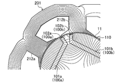
- FIG. 9 is an enlarged partial cross-sectional view showing a part of the rotor (11) shown in FIG. In FIG. 9, the hatching of the permanent magnet (100) and the rotor core (110) is not shown.
- the minimum radial distance (L2) from the outer peripheral surface of the magnet body (101) to the outer edge of the rotor core (110) is the magnet body (101) and the magnet end (102). ) To the outer edge of the rotor core (110) from the connection point (P) (specifically, the bending point on the outer peripheral side).
- the minimum radial distance (L2) is the radial distance from the outermost peripheral point (Q) of the magnet body (101) to the outer edge of the rotor core (110).
- the radial direction from the tip of the magnet end (102) (specifically, the center of the tip of the magnet end (102)) to the outer edge of the rotor core (110) The distance (L3) is shorter than the minimum radial direction distance (L2) from the outer peripheral surface of the magnet body (101) to the outer edge of the rotor core (110).
- the magnet end (102) extends in the radial direction of the rotor core (110). Specifically, the extending direction (X) of the magnet end (102) (in this example, the direction of the center line of the magnet end (102)) coincides with the radial direction of the rotor core (110).
- Each of the permanent magnets (100, 100,...) Is formed symmetrically with respect to the magnetic pole center line (PC) of the permanent magnet (100), and the outermost peripheral point (Q) of the magnet body (101) is the magnetic pole center line. (PC) is placed on.
- the extension width (W) of the magnet end (102) (specifically, the length in the width direction of the tip surface of the magnet end (102)) is greater than the extension length (L) of the magnet end (102).
- the magnetization direction (D2) of the magnet end (102) intersects the magnetic pole center line (PC) on the outer peripheral side of the magnet body (101), and the magnetization direction (D2) of the magnet end (102) )
- the permanent magnet (100) can be easily magnetized (magnetized) so that the inclination angle ( ⁇ 2) is larger than the inclination angle ( ⁇ 1) of the magnetization direction (D1) of the magnet body (101). .
- each of the permanent magnets (100, 100,...) The outer peripheral surface of the magnet body (101) and the rotor core (110) are bent by projecting the magnet body (101) toward the outer edge of the rotor core (110). The opposing distance between the outer edges of the two can be reduced. Thus, magnetic saturation can be easily generated in the portion between the outer peripheral surface of the permanent magnet (100) and the outer edge of the rotor core (110) (that is, the outer peripheral portion of the rotor core (110)). ) D-axis inductance can be reduced.
- the magnet body (101) is bent convexly toward the outer edge of the rotor core (110), and the magnet end (102) is directed toward the outer edge of the rotor core (110).
- the area of the outer peripheral surface (that is, the magnetic pole surface) of the permanent magnet (100) is increased as compared with the case where the magnet body (101) is formed in a straight line (for example, in the case of FIG. 3). Can do.
- the amount of flux linkage of permanent magnet (100) can be increased.
- each of the permanent magnets (100, 100,...) The magnet body (101) and the pair of magnet ends (102, 102) are integrally formed, so that the magnet body (101) and the magnet ends (102) are formed. The generation of leakage magnetic flux between the two can be suppressed. Thereby, the amount of flux linkage of permanent magnet (100) can be increased.
- the current limit value ie, the ratio of the interlinkage magnetic flux of the permanent magnet (100) to the d-axis inductance of the rotor (11) ( ⁇ a / Ld) (ie, The upper limit value of the current that can be applied to the coil (200) of the stator (12) is defined, and the current limit value decreases as the ratio of the flux linkage to the d-axis inductance ( ⁇ a / Ld) decreases. turn into. That is, the smaller the ratio of the flux linkage to the d-axis inductance ( ⁇ a / Ld), the more severe the current limitation in the rotation control of the rotor (11).
- the d-axis inductance of the rotor (11) can be decreased and the amount of flux linkage of the permanent magnet (100) can be increased.
- the ratio ( ⁇ a / Ld) of the flux linkage with respect to can be increased.
- the minimum radial distance (L2) from the outer peripheral surface of the magnet main body (101) to the outer edge of the rotor core (110) is determined by the magnet main body (101) and the magnet end.
- the outer peripheral surface of the magnet body (101) is brought closer to the outer edge of the rotor core (110) by making it shorter than the radial distance (L1) from the connection point (P) to the rotor core (110) to the outer edge of the rotor core (110). be able to.
- the radial distance (L3) from the tip of the magnet end (102) to the outer edge of the rotor core (110) is determined from the outer peripheral surface of the magnet body (101) to the rotor core (101).
- the tip of the magnet end (102) can be brought closer to the outer edge of the rotor core (110) by making it shorter than the minimum radial distance (L2) to the outer edge of 110).
- the magnetic end (102) is formed so as to extend in the radial direction of the rotor core (110), thereby effectively using the magnetic flux of the magnet end (102). Can do. That is, while facilitating the flow of magnetic flux between the magnet end (102) of the permanent magnet (100) and the opposing tooth portion (tooth portion (212) facing the permanent magnet (100)) of the stator (12), The flow of magnetic flux between the magnet end portion (102) of the permanent magnet (100) and the adjacent tooth portion (another tooth portion (212) adjacent to the opposing tooth portion) of the stator (12) can be suppressed. Thereby, the amount of flux linkage of permanent magnet (100) can further be increased.
- each of the permanent magnets (100, 100,...) So as to be symmetric with respect to the magnetic pole center line (PC), symmetry of the magnetic flux distribution in the permanent magnet (100) can be ensured. Thereby, the torque ripple which generate
- the minimum radial distance (L2) from the outer peripheral surface of the magnet body (101) to the outer edge of the rotor core (110) is the magnet body (101) and the magnet end. It may be longer than the radial distance (L1) from the connection point (P) to (102) to the outer edge of the rotor core (110), or may be the same length as the radial distance (L1).
- the radial distance (L3) from the tip of the magnet end (102) to the outer edge of the rotor core (110) is the minimum radial distance (L2) from the outer peripheral surface of the magnet body (101) to the outer edge of the rotor core (110) May be longer or may be the same length as the minimum radial distance (L2).
- the magnet end (102) may not extend in the radial direction of the rotor core (110). Further, each of the permanent magnets (100, 100,...) May not be formed symmetrically with respect to the magnetic pole center line (PC).
- the permanent magnet (100) is constituted by a bonded magnet is taken as an example, but the permanent magnet (100) may be constituted by a sintered magnet.
- a permanent magnet (100) can be configured by combining a sintered magnet that becomes a magnet body (101) and a sintered magnet that becomes a magnet end (102, 102) in a magnet slot (S110). . That is, the pair of magnet end portions (102, 102) may not be formed integrally with the magnet main body portion (101).
- the coil (202) is wound around the teeth part (212, 212, etc.
- the coil (202) is arranged on the teeth part (212, 212,%) By the distributed winding method. It may be wound.
- each magnet body (101) of the permanent magnet (100, 100 in the first modification (FIG. 6), the second modification (FIG. 7), and the third modification (FIG. 8) of the rotor (11), each magnet body (101) of the permanent magnet (100, 100,.
- magnet body part (101) may be formed in the wave shape which has a plurality of vertices.
- each magnet main-body part (101) of a permanent magnet (100,100, ...) becomes the V character from which one vertex becomes the outermost periphery point (Q).
- the magnet body portion (101) has a wavy shape in which two or more vertices of the plurality of vertices become the outermost peripheral point (Q) (the rotor core (110) as a whole). May be formed in a convex shape toward the outer edge.
- the rotating electric machine (10) constitutes an electric motor
- the rotating electric machine (10) may constitute an electric generator
- the rotary electric machine described above is useful as an electric motor for driving a compressor of an air conditioner.
Landscapes
- Engineering & Computer Science (AREA)
- Power Engineering (AREA)
- Permanent Field Magnets Of Synchronous Machinery (AREA)
- Permanent Magnet Type Synchronous Machine (AREA)
- Iron Core Of Rotating Electric Machines (AREA)
Abstract
Description
図1および図2は、実施形態による回転電気機械(10)の横断面および縦断面をそれぞれ示している。例えば、回転電気機械(10)は、空気調和機の圧縮機(図示を省略)を駆動するための電動機として用いられる。この例では、回転電気機械(10)は、埋込磁石型モータ(IPMモータ)を構成している。回転電気機械(10)は、ロータ(11)と、ステータ(12)とを備え、ケーシング(30)(例えば、圧縮機のケーシング)に収容されている。ロータ(11)は、駆動軸(20)に固定されている。
ステータ(12)には、ロータ(11)が回転可能に挿通される。この例では、ロータ(11)は、円柱状に形成され、ステータ(12)は、円筒状に形成されている。具体的には、ステータ(12)は、ステータコア(201)と、コイル(202)とを備えている。なお、図1では、ステータコア(201)のハッチングの図示を省略している。
ステータコア(201)は、円筒状に形成されている。具体的には、ステータコア(201)は、バックヨーク部(211)と、複数(この例では、6つ)のティース部(212,212,…)と、複数(この例では、6つ)のツバ部(213,213,…)とを備えている。例えば、ステータコア(201)は、電磁鋼板をプレス加工によって打ち抜いて複数の積層板(円環状の平板)を作製し、複数の積層板を軸方向に積層することにより構成されていてもよい。
コイル(202)は、集中巻方式によりティース部(212,212,…)に巻回されている。すなわち、1つのティース部(212)ごとにコイル(202)が巻回され、巻回されたコイル(202)は、コイル用スロット(S200)内に収容されている。これにより、ティース部(212,212,…)の各々において電磁石が形成されている。
次に、図1~図3を参照して、ロータ(11)について説明する。ロータ(11)は、ロータコア(110)と、複数(この例では、4つ)の永久磁石(100,100,…)とを有している。なお、図1および図3では、ロータコア(110)のハッチングの図示を省略している。
ロータコア(110)は、円柱状に形成されている。例えば、ロータコア(110)は、電磁鋼板をプレス加工によって打ち抜いて複数の積層板(円形状の平板)を作製し、複数の積層板を軸方向に積層することにより構成されていてもよい。また、ロータコア(110)の中心には、軸穴(S120)が形成されている。軸穴(S120)には、圧入などによって駆動軸(20)が固定されている。
また、ロータコア(110)には、複数の永久磁石(100,100,…)をそれぞれ収容するための複数(この例では、4つ)の磁石スロット(S110,S110,…)が形成されている。磁石スロット(S110,S110,…)は、ロータコア(110)の周方向(すなわち、ロータ(11)の回転中心(O)回り)に所定のピッチ(この例では、90度ピッチ)で配列されている。また、磁石スロット(S110,S110,…)は、ロータコア(110)を軸方向に貫通している。そして、磁石スロット(S110,S110,…)の各々は、スロット本体部(S111)と、一対のスロット端部(S112,S112)とを有している。
永久磁石(100,100,…)は、ロータコア(110)の磁石スロット(S110,S110,…)にそれぞれ収容されている。すなわち、永久磁石(100,100,…)は、ロータコア(110)の周方向(すなわち、ロータ(11)の回転中心(O)回り)に所定のピッチ(この例では、90度ピッチ)でロータコア(110)に配列されて埋設されている。また、永久磁石(100)は、その外周面(ロータ(11)の外周側に対向する面)および内周面(回転中心(O)に対向する面)が磁極面となるように構成されている。すなわち、永久磁石(100)の外周面および内周面のうち、一方の面がS極に構成され、他方の面がN極に構成されている。そして、永久磁石(100,100,…)は、ロータ(11)の周方向にS極の磁極面とN極の磁極面とが交互に位置するように配置されている。
永久磁石(100,100,…)は、磁石スロット(S110,S110,…)の穴形状に対応する形状を有している。すなわち、永久磁石(100,100,…)の各々は、磁石本体部(101)と、一対の磁石端部(102,102)とを有している。
また、永久磁石(100)の磁石端部(102)の磁化方向(D2)は、永久磁石(100)の磁石本体部(101)の外周側において永久磁石(100)の磁極中心線(PC)と交差している。永久磁石(100)の磁極中心線(PC)に対する永久磁石(100)の磁石端部(102)の磁化方向(D2)の傾斜角度(θ2)は、永久磁石(100)の磁極中心線(PC)に対する永久磁石(100)の磁石本体部(101)の磁化方向(D1)の傾斜角度(θ1)よりも大きくなっている。すなわち、この例では、永久磁石(100)は、磁石端部(102)の磁化方向(D2)が磁石本体部(101)の外周側において磁極中心線(PC)と交差し、磁極中心線(PC)に対する磁石端部(102)の磁化方向(D2)の傾斜角度(θ2)が磁極中心線(PC)に対する磁石本体部(101)の磁化方向(D1)の傾斜角度(θ1)よりも大きくなるように、磁化(着磁)されている。なお、この例では、磁化方向(D1)の傾斜角度(θ1)は、ゼロとなっている。すなわち、磁化方向(D1)は、磁極中心線(PC)と平行となっている。
次に、図4および図5を参照して、永久磁石(100,100,…)の漏れ磁束について説明する。図4は、ロータ(11)の比較例(以下、ロータ(91)と表記)の一部を拡大して示した部分横断面図に対応する磁束線図であり、図5は、この実施形態におけるロータ(11)の一部を拡大して示した部分横断面図に対応する磁束線図である。なお、図4および図5では、磁束線を細線で示している。また、説明の便宜上、図4および図5では、コイル(202)および軸穴(S120)の図示を省略し、永久磁石およびティース部の符号の末尾に“a”または“b”を付している。
図4のように、ロータ(91)では、ロータコア(910)に複数(この例では、4つ)の永久磁石(900,900,…)が埋設されている。永久磁石(900,900,…)の各々において、一対の磁石端部(902,902)は、磁石本体部(901)の外周面側に折れ曲がらずに磁石本体部(901)の周方向の両端の延長線に沿ってロータコア(910)の外縁へ向けて延びている。また、永久磁石(900,900)の各々において、一対の磁石端部(902,902)の磁化方向は、磁石本体部(901)の磁化方向と平行となっている。
一方、この実施形態におけるロータ(11)では、永久磁石(100,100,…)の各々において、一対の磁石端部(102,102)は、磁石本体部(101)の外周面側に折れ曲がって磁石本体部(101)の周方向の両端からロータコア(110)の外縁へ向けて延びている。また、永久磁石(100,100,…)の各々において、磁石端部(102)の磁化方向(D2)は、磁石本体部(101)の外周側において磁極中心線(PC)と交差し、磁極中心線(PC)に対する磁石端部(102)の磁化方向(D2)の傾斜角度(θ2)は、磁極中心線(PC)に対する磁石本体部(101)の磁化方向(D1)の傾斜角度(θ1)よりも大きくなっている。そのため、永久磁石(100)の磁石端部(102)の磁束は、永久磁石(100)の磁石本体部(101)の外周側において永久磁石(100)の磁極中心線(PC)へ向けて延びやすくなっている。したがって、図5のように、永久磁石(100a)の磁石端部(102a)の内側面(磁極中心線(PC)に近い側の面)から延びる磁束は、永久磁石(100a)に対向する対向ティース部(212a)に対しては鎖交しやすく、隣接ティース部(212b)に対しては鎖交しにくくなっている。例えば、永久磁石(100a)の磁石端部(102a)の内側面から延びる磁束は、隣接ティース部(212b)ではなく対向ティース部(212a)に鎖交し、その後、隣接ティース(212b)を経由して永久磁石(100a)に隣接する永久磁石(100b)の磁石端部(102b)の内側面に到達する。このように、永久磁石(100a)の磁石端部(102a)から対向ティース部(212a)を経由せずに隣接ティース部(212b)を経由して永久磁石(100a)に隣接する永久磁石(100b)に到達する磁束(すなわち、漏れ磁束)を低減することができるので、図5に示した永久磁石(100a)の鎖交磁束量は、図4に示した永久磁石(900a)の鎖交磁束量よりも多くなっている。
以上のように、この実施形態におけるロータ(11)では、永久磁石(100)の磁石端部(102)の磁束が永久磁石(100)の磁石本体部(101)の外周側において永久磁石(100)の磁極中心線(PC)へ向けて延びやすくなっているので、永久磁石(100)の漏れ磁束を低減することができる。これにより、永久磁石(100)の鎖交磁束量の低下を抑制することができるので、回転電気機械(10)の運転効率の低下(例えば、回転電気機械(10)の銅損の増加)を抑制することができる。
なお、スロット端部(S112)の延伸幅は、スロット端部(S112)の延伸長さよりも短くなっていることが好ましい。すなわち、磁石端部(102)の延伸幅(W)は、磁石端部(102)の延伸長さ(L)よりも短くなっていることが好ましい。磁石端部(102)の延伸長さは、磁石端部(102)の延伸方向における長さのことであり、磁石端部(102)の延伸幅は、磁石端部(102)の延伸方向と直交する幅方向における長さのことである。なお、図3では、磁石端部(102)の延伸幅(W)は、磁石端部(102)の基端部から先端部まで同幅となっている。
なお、永久磁石(100)をボンド磁石によって構成する場合、焼結磁石(特に、希土類焼結磁石)よりもボンド磁石のほうが残留磁束密度が低いので、永久磁石(100)の磁束を増加させるために、永久磁石(100)の全長(ロータコア(110)の径方向を横切って延びる長さ)を長くして永久磁石(100)の表面積(より具体的には、永久磁石(100)の外周面の面積)を大きくする場合が多い。すなわち、永久磁石(100)をボンド磁石によって構成する場合、永久磁石(100)を焼結磁石によって構成する場合よりも、永久磁石(100)の漏れ磁束が増加しやすい形状となっている。したがって、永久磁石(100)をボンド磁石によって構成する場合に、永久磁石(100)を図3のように構成することが特に有効である。すなわち、一対の磁石端部(102,102)が磁石本体部(101)の外周面側に折れ曲がって磁石本体部(101)の周方向の両端からロータコア(110)の外縁へ向けて延びるように永久磁石(100)を形成し、磁石端部(102)の磁化方向(D2)が磁石本体部(101)の外周側において磁極中心線(PC)と交差し、磁極中心線(PC)に対する磁石端部(102)の磁化方向(D2)の傾斜角度(θ2)が磁極中心線(PC)に対する磁石本体部(101)の磁化方向(D1)の傾斜角度(θ1)よりも大きくなるように永久磁石(100)を磁化(着磁)することにより、ボンド磁石(すなわち、永久磁石(100))の漏れ磁束を効果的に低減することができる。
また、ティース部(212)の内周面(より具体的には、ツバ部(213)の内周面)の面積が大きくなるほど、永久磁石(900)の漏れ磁束が増加しやすくなる傾向にある。そして、集中巻方式によりコイル(202)がティース部(212,212,…)に巻回されているステータ(12)(以下、集中巻方式のステータ(12)と表記)では、分布巻方式によりコイル(202)がティース部(212,212,…)に巻回されているステータ(12)(以下、分布巻方式のステータ(12)と表記)よりも、ティース部(212)の内周面の面積が大きくなる傾向にある。すなわち、集中巻方式のステータ(12)は、分布巻方式のステータ(12)よりも、永久磁石(100)の漏れ磁束が増加しやすくなっている。したがって、集中巻方式によりコイル(202)がティース部(212,212,…)に巻回されている場合に、永久磁石(100)を図3のように構成することが特に有効である。
図6のように、永久磁石(100)の磁石本体部(101)は、ロータコア(110)の回転中心(O)へ向けて凸状に曲がるように形成されていてもよい。この例では、永久磁石(100)の磁石本体部(101)は、ロータコア(110)の回転中心(O)へ向けて凸状となるV字状に形成されている。また、永久磁石(100)の磁石本体部(101)は、永久磁石(100)の磁極中心線(PC)に対して対称となるように形成されている。すなわち、この例では、磁石本体部(101)は、磁極中心線(PC)を軸として線対称となるV字状(内周側に凸のV字状)に形成されている。なお、この例においても、永久磁石(100)の一対の磁石端部(102,102)は、磁石本体部(101)の外周面側に折れ曲がって磁石本体部(101)の周方向の両端から連続してロータコア(110)の外縁へ向けて延びている。
以上のように構成した場合も、永久磁石(100)の磁石端部(102)の磁束が永久磁石(100)の磁石本体部(101)の外周側において永久磁石(100)の磁極中心線(PC)へ向けて延びやすくなっているので、永久磁石(100)の漏れ磁束を低減することができる。
図7のように、永久磁石(100)の磁石本体部(101)は、ロータコア(110)の回転中心(O)へ向けて凸状となる円弧状に形成されていてもよい。この例では、永久磁石(100)の磁石本体部(101)は、永久磁石(100)の磁極中心線(PC)に対して対称に形成されている。すなわち、この例では、磁石本体部(101)は、磁極中心線(PC)を軸として線対称となる円弧状(内周側に凸の円弧状)に形成されている。なお、この例においても、永久磁石(100)の一対の磁石端部(102,102)は、磁石本体部(101)の外周面側に折れ曲がって磁石本体部(101)の周方向の両端から連続してロータコア(110)の外縁へ向けて延びている。すなわち、一対の磁石端部(102,102)は、磁石本体部(101)の周方向の両端の延長線(この例では、接線方向に延びる延長線)に対して永久磁石(100)の磁極中心線(PC)側に傾斜しつつ磁石本体部(101)の周方向の両端からロータコア(110)の外縁へそれぞれ延びている。
以上のように構成した場合も、永久磁石(100)の磁石端部(102)の磁束が永久磁石(100)の磁石本体部(101)の外周側において永久磁石(100)の磁極中心線(PC)へ向けて延びやすくなっているので、永久磁石(100)の漏れ磁束を低減することができる。
図8のように、永久磁石(100)の磁石本体部(101)は、ロータコア(110)の外縁へ向けて凸状に曲がるように形成されていてもよい。この例では、永久磁石(100)の磁石本体部(101)は、ロータコア(110)の外縁へ向けて凸状となるV字状に形成されている。また、永久磁石(100)の磁石本体部(101)は、永久磁石(100)の磁極中心線(PC)に対して対称となるように形成されている。すなわち、この例では、磁石本体部(101)は、磁極中心線(PC)を軸として線対称となるV字状(外周側に凸のV字状)に形成されている。なお、この例においても、永久磁石(100)の一対の磁石端部(102,102)は、磁石本体部(101)の外周面側に折れ曲がって磁石本体部(101)の周方向の両端から連続してロータコア(110)の外縁へ向けて延びている。
次に、図9を参照して、図8に示したロータ(11)の構造について詳しく説明する。なお、図9は、図8に示したロータ(11)の一部を拡大して示す部分横断面図である。また、図9では、永久磁石(100)およびロータコア(110)のハッチングの図示を省略している。
以上のように構成した場合も、永久磁石(100)の磁石端部(102)の磁束が永久磁石(100)の磁石本体部(101)の外周側において永久磁石(100)の磁極中心線(PC)へ向けて延びやすくなっているので、永久磁石(100)の漏れ磁束を低減することができる。
以上の説明では、永久磁石(100)がボンド磁石によって構成されている場合を例に挙げたが、永久磁石(100)は、焼結磁石によって構成されていてもよい。例えば、磁石本体部(101)となる焼結磁石と磁石端部(102,102)となる焼結磁石とを組み合わせ磁石スロット(S110)に収容することにより、永久磁石(100)を構成することができる。すなわち、一対の磁石端部(102,102)は、磁石本体部(101)と一体に形成されていなくてもよい。
20 駆動軸
30 ケーシング
11 ロータ
12 ステータ
100 永久磁石
101 磁石本体部
102 磁石端部
110 ロータコア
S110 磁石スロット
PC 磁極中心線
D1,D2 磁化方向
θ1,θ2 傾斜角度
201 ステータコア
202 コイル
211 バックヨーク部
212 ティース部
213 ツバ部
Claims (9)
- ロータコア(110)と、
上記ロータコア(110)に埋設された複数の永久磁石(100)とを備え、
上記永久磁石(100)は、上記ロータコア(110)の径方向を横切るように形成された磁石本体部(101)と、該磁石本体部(101)の外周面側に折れ曲がり該磁石本体部(101)の周方向の両端から該ロータコア(110)の外縁へ向けて延びる一対の磁石端部(102)とを有し、
上記永久磁石(100)の磁石端部(102)の磁化方向(D2)は、該永久磁石(100)の磁石本体部(101)の外周側において該永久磁石(100)の磁極中心線(PC)と交差し、
上記永久磁石(100)の磁極中心線(PC)に対する該永久磁石(100)の磁石端部(102)の磁化方向(D2)の傾斜角度(θ2)は、該永久磁石(100)の磁極中心線(PC)に対する該永久磁石(100)の磁石本体部(101)の磁化方向(D1)の傾斜角度(θ1)よりも大きくなっている
ことを特徴とするロータ。 - 請求項1において、
上記永久磁石(100)は、ボンド磁石によって構成されている
ことを特徴とするロータ。 - 請求項2において、
上記永久磁石(100)の磁石端部(102)の延伸幅(W)は、該永久磁石(100)の磁石端部(102)の延伸長さ(L)よりも短くなっている
ことを特徴とするロータ。 - 請求項2または3において、
上記永久磁石(100)の磁石本体部(101)は、上記ロータコア(110)の外縁へ向けて凸状に曲がるように形成され、
上記永久磁石(100)の一対の磁石端部(102)は、該該永久磁石(100)の磁石本体部(101)の周方向の両端から連続して上記ロータコア(110)の外縁へ向けて延びるように形成されている
ことを特徴とするロータ。 - 請求項4において、
上記永久磁石(100)の磁石本体部(101)の外周面から上記ロータコア(110)の外縁までの最小径方向距離(L2)は、該永久磁石(100)の磁石本体部(101)と磁石端部(102)との接続点(P)から該ロータコア(110)の外縁までの径方向距離(L1)よりも短くなっている
ことを特徴とするロータ。 - 請求項4または5において、
上記永久磁石(100)の磁石端部(102)の先端から上記ロータコア(110)の外縁までの径方向距離(L3)は、該永久磁石(100)の磁石本体部(101)の外周面から該ロータコア(110)の外縁までの最小径方向距離(L2)よりも短くなっている
ことを特徴とするロータ。 - 請求項4~6のいずれか1項において、
上記永久磁石(100)の磁石端部(102)は、上記ロータコア(110)の径方向に延びている
ことを特徴とするロータ。 - 請求項4~7のいずれか1項において、
上記永久磁石(100)は、該永久磁石(100)の磁極中心線(PC)に対して対称に形成されている
ことを特徴とするロータ。 - 請求項1~8のいずれか1項に記載のロータ(11)と、
上記ロータ(11)が挿通されるステータ(12)とを備えている
ことを特徴とする回転電気機械。
Priority Applications (5)
| Application Number | Priority Date | Filing Date | Title |
|---|---|---|---|
| CN201380049368.0A CN104685764B (zh) | 2012-09-28 | 2013-09-30 | 转子及旋转电气设备 |
| AU2013321841A AU2013321841B2 (en) | 2012-09-28 | 2013-09-30 | Rotor and rotary electric machine |
| EP13841609.4A EP2903138B1 (en) | 2012-09-28 | 2013-09-30 | Rotor and rotary electric machine |
| US14/431,268 US10122231B2 (en) | 2012-09-28 | 2013-09-30 | Rotor and rotary electric machine |
| ES13841609T ES2880112T3 (es) | 2012-09-28 | 2013-09-30 | Rotor y máquina eléctrica rotativa |
Applications Claiming Priority (2)
| Application Number | Priority Date | Filing Date | Title |
|---|---|---|---|
| JP2012-218294 | 2012-09-28 | ||
| JP2012218294 | 2012-09-28 |
Publications (1)
| Publication Number | Publication Date |
|---|---|
| WO2014050154A1 true WO2014050154A1 (ja) | 2014-04-03 |
Family
ID=50387580
Family Applications (1)
| Application Number | Title | Priority Date | Filing Date |
|---|---|---|---|
| PCT/JP2013/005829 WO2014050154A1 (ja) | 2012-09-28 | 2013-09-30 | ロータおよび回転電気機械 |
Country Status (7)
| Country | Link |
|---|---|
| US (1) | US10122231B2 (ja) |
| EP (1) | EP2903138B1 (ja) |
| JP (2) | JP5713075B2 (ja) |
| CN (1) | CN104685764B (ja) |
| AU (1) | AU2013321841B2 (ja) |
| ES (1) | ES2880112T3 (ja) |
| WO (1) | WO2014050154A1 (ja) |
Cited By (1)
| Publication number | Priority date | Publication date | Assignee | Title |
|---|---|---|---|---|
| JPWO2016031054A1 (ja) * | 2014-08-29 | 2017-04-27 | 三菱電機株式会社 | 圧縮機のモータ、冷凍サイクル装置 |
Families Citing this family (12)
| Publication number | Priority date | Publication date | Assignee | Title |
|---|---|---|---|---|
| JP6272550B2 (ja) | 2015-03-03 | 2018-01-31 | 三菱電機株式会社 | リラクタンスモータ、およびリラクタンスモータに用いられるロータコアの製造方法 |
| JP6709522B2 (ja) * | 2015-09-29 | 2020-06-17 | ダイキン工業株式会社 | ロータ |
| US20180115206A1 (en) * | 2015-10-01 | 2018-04-26 | Panasonic Intellectual Property Management Co., Lt | Electric motor element, electric motor, and device |
| EP3413440B1 (en) | 2017-06-06 | 2023-05-31 | GE Renewable Technologies Wind B.V. | Magnet module and electrical machine |
| JP6939734B2 (ja) * | 2017-08-01 | 2021-09-22 | 株式会社デンソー | 磁石ユニット及び回転電機駆動システム |
| CN112689939A (zh) * | 2018-11-09 | 2021-04-20 | 爱信艾达株式会社 | 旋转电机用转子铁芯 |
| DE102019107452A1 (de) * | 2019-03-22 | 2020-09-24 | Feaam Gmbh | Rotor und elektrische Maschine |
| CN114072989A (zh) * | 2019-07-11 | 2022-02-18 | 三菱电机株式会社 | 转子、电动机及转子的制造方法 |
| US11710994B2 (en) * | 2020-02-25 | 2023-07-25 | Tdk Corporation | Rotating electrical machine |
| US20220311294A1 (en) * | 2021-03-25 | 2022-09-29 | Nidec Motor Corporation | Rotor with arcuate magnets |
| JP7090773B1 (ja) * | 2021-04-01 | 2022-06-24 | 三菱電機株式会社 | 回転電機 |
| WO2024072384A1 (en) * | 2022-09-28 | 2024-04-04 | Nidec Motor Corporation | Rotor with arcuate magnets |
Citations (5)
| Publication number | Priority date | Publication date | Assignee | Title |
|---|---|---|---|---|
| JP2002044889A (ja) * | 2000-05-17 | 2002-02-08 | Hitachi Metals Ltd | 3軸異方性一体形永久磁石および回転機 |
| JP2004346757A (ja) | 2003-05-20 | 2004-12-09 | Daikin Ind Ltd | 圧縮機および空気調和装置 |
| JP2004357489A (ja) * | 2003-05-28 | 2004-12-16 | Akira Chiba | 単方向着磁の永久磁石モータ |
| JP2005051979A (ja) * | 2003-07-30 | 2005-02-24 | Meiso Shu | 自励式永久磁石同期モータの回転子装置 |
| JP3145510U (ja) * | 2007-08-10 | 2008-10-09 | 瑞智精密股▲ふん▼有限公司 | 永久磁石式電動機の構造 |
Family Cites Families (12)
| Publication number | Priority date | Publication date | Assignee | Title |
|---|---|---|---|---|
| JPH0638415A (ja) * | 1992-07-22 | 1994-02-10 | Hitachi Metals Ltd | 永久磁石式ロータ |
| JPH10304610A (ja) | 1997-04-22 | 1998-11-13 | Toshiba Corp | 永久磁石回転子及び永久磁石回転子用抜き板の製造方法 |
| KR100263445B1 (ko) * | 1997-11-13 | 2000-08-01 | 윤종용 | 브러시리스 dc모터용 회전자 |
| JP4089072B2 (ja) * | 1998-10-23 | 2008-05-21 | 三菱電機株式会社 | 永久磁石埋込み形モータ |
| JP2002078259A (ja) | 2000-08-31 | 2002-03-15 | Yamaha Motor Co Ltd | 永久磁石回転子 |
| JP2003032926A (ja) * | 2001-07-10 | 2003-01-31 | Teijin Seiki Co Ltd | 永久磁石型モータ |
| EP1471621A3 (de) * | 2003-04-24 | 2005-12-14 | Minebea Co., Ltd. | Rotorkörper für einen Elektromotor |
| JP2005020991A (ja) * | 2003-06-04 | 2005-01-20 | Hitachi Metals Ltd | 回転子およびその製造方法 |
| CN101777809A (zh) * | 2004-04-06 | 2010-07-14 | 日立金属株式会社 | 转子及其制造方法 |
| JP4574297B2 (ja) | 2004-09-13 | 2010-11-04 | 日産自動車株式会社 | 回転電機のロータ |
| US7598645B2 (en) * | 2007-05-09 | 2009-10-06 | Uqm Technologies, Inc. | Stress distributing permanent magnet rotor geometry for electric machines |
| JP5468215B2 (ja) * | 2008-06-09 | 2014-04-09 | ダイキン工業株式会社 | 空気調和機及び空気調和機の製造方法 |
-
2013
- 2013-09-30 ES ES13841609T patent/ES2880112T3/es active Active
- 2013-09-30 JP JP2013205215A patent/JP5713075B2/ja active Active
- 2013-09-30 WO PCT/JP2013/005829 patent/WO2014050154A1/ja active Application Filing
- 2013-09-30 US US14/431,268 patent/US10122231B2/en active Active
- 2013-09-30 AU AU2013321841A patent/AU2013321841B2/en active Active
- 2013-09-30 JP JP2013205216A patent/JP2014082928A/ja active Pending
- 2013-09-30 CN CN201380049368.0A patent/CN104685764B/zh active Active
- 2013-09-30 EP EP13841609.4A patent/EP2903138B1/en active Active
Patent Citations (5)
| Publication number | Priority date | Publication date | Assignee | Title |
|---|---|---|---|---|
| JP2002044889A (ja) * | 2000-05-17 | 2002-02-08 | Hitachi Metals Ltd | 3軸異方性一体形永久磁石および回転機 |
| JP2004346757A (ja) | 2003-05-20 | 2004-12-09 | Daikin Ind Ltd | 圧縮機および空気調和装置 |
| JP2004357489A (ja) * | 2003-05-28 | 2004-12-16 | Akira Chiba | 単方向着磁の永久磁石モータ |
| JP2005051979A (ja) * | 2003-07-30 | 2005-02-24 | Meiso Shu | 自励式永久磁石同期モータの回転子装置 |
| JP3145510U (ja) * | 2007-08-10 | 2008-10-09 | 瑞智精密股▲ふん▼有限公司 | 永久磁石式電動機の構造 |
Non-Patent Citations (1)
| Title |
|---|
| See also references of EP2903138A4 |
Cited By (3)
| Publication number | Priority date | Publication date | Assignee | Title |
|---|---|---|---|---|
| JPWO2016031054A1 (ja) * | 2014-08-29 | 2017-04-27 | 三菱電機株式会社 | 圧縮機のモータ、冷凍サイクル装置 |
| US10992213B2 (en) | 2014-08-29 | 2021-04-27 | Mitsubishi Electric Corporation | Motor of compressor and refrigeration cycle apparatus |
| US11557950B2 (en) | 2014-08-29 | 2023-01-17 | Mitsubishi Electric Corporation | Motor of compressor and refrigeration cycle apparatus |
Also Published As
| Publication number | Publication date |
|---|---|
| AU2013321841A1 (en) | 2015-05-14 |
| CN104685764B (zh) | 2017-12-01 |
| AU2013321841B2 (en) | 2016-02-25 |
| CN104685764A (zh) | 2015-06-03 |
| JP5713075B2 (ja) | 2015-05-07 |
| EP2903138B1 (en) | 2021-06-16 |
| JP2014082928A (ja) | 2014-05-08 |
| US10122231B2 (en) | 2018-11-06 |
| ES2880112T3 (es) | 2021-11-23 |
| EP2903138A4 (en) | 2016-06-01 |
| US20150372547A1 (en) | 2015-12-24 |
| EP2903138A1 (en) | 2015-08-05 |
| JP2014082927A (ja) | 2014-05-08 |
Similar Documents
| Publication | Publication Date | Title |
|---|---|---|
| JP5713075B2 (ja) | ロータおよび回転電気機械 | |
| JP6806352B2 (ja) | 回転電機、回転子鉄心の製造方法 | |
| JP5762569B2 (ja) | 永久磁石埋込型モータの回転子ならびにこれを用いた圧縮機、送風機および冷凍空調装置 | |
| JP5663936B2 (ja) | 永久磁石式回転電機 | |
| JP5813254B2 (ja) | 永久磁石式回転電機 | |
| KR101736369B1 (ko) | 디텐트 토크가 낮은 3상 전기 모터 | |
| WO2011007694A1 (ja) | 永久磁石式同期モータ | |
| JP6002449B2 (ja) | 永久磁石回転電機、エレベーター巻上機 | |
| JP5805191B2 (ja) | 永久磁石埋込型モータならびにこれを用いた圧縮機、送風機および冷凍空調装置 | |
| JP2007330025A (ja) | モータ | |
| CN105052015A (zh) | 轴向型旋转电机 | |
| JP6429992B2 (ja) | 永久磁石埋込型電動機、送風機および冷凍空調機 | |
| JP2018137853A (ja) | 埋込磁石同期モータ | |
| JP2014236577A (ja) | 永久磁石式回転電機 | |
| JP5490171B2 (ja) | 回転子および同期電動機 | |
| JP2013236418A (ja) | 回転電気機械 | |
| WO2013111301A1 (ja) | 同期電動機の回転子およびその製造方法ならびに同期電動機 | |
| CN204304642U (zh) | 旋转电机 | |
| JPWO2017171037A1 (ja) | ロータ及びロータの設計方法 | |
| JP2014007796A (ja) | 回転電機のロータ構造 | |
| CN102761219B (zh) | 旋转电机及转子 | |
| WO2022219896A1 (ja) | 回転電機のロータ、回転電機及び電動駆動システム | |
| JP2019004552A (ja) | 回転電気機械 |
Legal Events
| Date | Code | Title | Description |
|---|---|---|---|
| 121 | Ep: the epo has been informed by wipo that ep was designated in this application |
Ref document number: 13841609 Country of ref document: EP Kind code of ref document: A1 |
|
| WWE | Wipo information: entry into national phase |
Ref document number: 2013841609 Country of ref document: EP |
|
| WWE | Wipo information: entry into national phase |
Ref document number: 14431268 Country of ref document: US |
|
| NENP | Non-entry into the national phase |
Ref country code: DE |
|
| ENP | Entry into the national phase |
Ref document number: 2013321841 Country of ref document: AU Date of ref document: 20130930 Kind code of ref document: A |