WO2014046115A1 - 車両用装飾部品の組み付け構造 - Google Patents
車両用装飾部品の組み付け構造 Download PDFInfo
- Publication number
- WO2014046115A1 WO2014046115A1 PCT/JP2013/075123 JP2013075123W WO2014046115A1 WO 2014046115 A1 WO2014046115 A1 WO 2014046115A1 JP 2013075123 W JP2013075123 W JP 2013075123W WO 2014046115 A1 WO2014046115 A1 WO 2014046115A1
- Authority
- WO
- WIPO (PCT)
- Prior art keywords
- pair
- vehicle
- decorative part
- claw
- decorative
- Prior art date
- Legal status (The legal status is an assumption and is not a legal conclusion. Google has not performed a legal analysis and makes no representation as to the accuracy of the status listed.)
- Ceased
Links
Images

Classifications
-
- B—PERFORMING OPERATIONS; TRANSPORTING
- B60—VEHICLES IN GENERAL
- B60R—VEHICLES, VEHICLE FITTINGS, OR VEHICLE PARTS, NOT OTHERWISE PROVIDED FOR
- B60R13/00—Elements for body-finishing, identifying, or decorating; Arrangements or adaptations for advertising purposes
- B60R13/02—Internal Trim mouldings ; Internal Ledges; Wall liners for passenger compartments; Roof liners
- B60R13/0206—Arrangements of fasteners and clips specially adapted for attaching inner vehicle liners or mouldings
-
- B—PERFORMING OPERATIONS; TRANSPORTING
- B60—VEHICLES IN GENERAL
- B60R—VEHICLES, VEHICLE FITTINGS, OR VEHICLE PARTS, NOT OTHERWISE PROVIDED FOR
- B60R13/00—Elements for body-finishing, identifying, or decorating; Arrangements or adaptations for advertising purposes
- B60R13/04—External Ornamental or guard strips; Ornamental inscriptive devices thereon
- B60R2013/046—Foot boards
Definitions
- the present invention relates to a structure for assembling a vehicle decorative part, and more particularly, to a structure for assembling a vehicle decorative part in which a tail end trim is assembled to a pair of left and right quarter lower trims.
- Patent Document 1 discloses a structure for assembling a tail end trim to a quarter lower trim as a structure for assembling a vehicle decorative part.
- a first engagement claw is provided on the back surface of the front wall of the tail end trim
- a second engagement claw is provided on the back surface of the upper wall
- the first engagement is provided on the quarter lower trim.
- a first engagement hole and a second engagement hole in which guide surfaces corresponding to the claw and the second engagement claw are formed are provided. Then, as the tail end trim is slid from the initial state in the protruding direction of the second engaging claw, the first engaging claw is guided by the guide surface of the first engaging hole, and the second engaging claw protrudes. After the position of the second engagement claw is determined in a direction orthogonal to the direction, the second engagement claw and the second engagement hole are configured to start engagement.
- the present invention has been made in view of these points, and an object of the present invention is to provide an assembly structure for a vehicle decorative component that can easily assemble a decorative component to another component with a simple structure. .
- a vehicle decorative part assembly structure is a vehicle decorative part assembly structure in which a vehicle body decorative part is assembled to another part, and at least one end of the decorative part.
- a pair of claw portions provided so as to protrude from the back surface, and a pair of opening holes provided on the upper surface of the other component corresponding to the pair of claw portions, respectively. It has at least one inclined surface portion that is chamfered by chamfering from the top portion to the side portion, and when assembling the decorative part, the inclined surface portion is guided while contacting the edge of the opening hole, The pair of claws are fitted into the pair of opening holes.
- the decorative part may be formed in a long shape, and the pair of claws may be provided on the back surface of at least one end in the longitudinal direction of the decorative part with a space therebetween.
- the decorative part is a tail end trim that is assembled with its longitudinal direction oriented in the vehicle width direction, and the other parts form the left and right side walls of the rear compartment, and the rear lower ends thereof are arranged in the vehicle width direction.
- a pair of quarter lower trims projecting from the inside of the tail end trim, the pair of claw portions projecting from the back surfaces of both ends in the longitudinal direction of the tail end trim, and the pair of opening holes You may provide in the upper surface of the part protrudingly formed by the back lower end part of the quarter lower trim.
- the opening hole may be formed in a rectangular shape, and the inclined surface portion may be provided corresponding to each side of the opening hole formed in a rectangular shape.
- the decorative part can be easily assembled to another part with a simple structure.
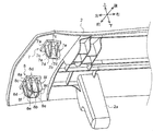
- (A) is a typical perspective view which shows the state before an assembly
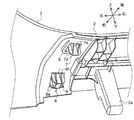
- (b) is a typical perspective view which shows the state after an assembly
- FIGS. 1 to 3 an assembly structure for a decorative part for a vehicle according to an embodiment of the present invention will be described.
- the same parts are denoted by the same reference numerals, and their names and functions are also the same. Therefore, detailed description thereof will not be repeated.
- the vehicle decorative part assembly structure of the present embodiment includes a long tail end trim (decorative part) 2 and a left quarter lower trim (other parts) that forms the left side wall of the rear luggage compartment. Parts) 3 and a right quarter lower trim (other parts) 4 that forms the right side wall of the rear cargo compartment.
- reference numeral 11 denotes a floor panel that forms the floor surface of the rear luggage compartment
- 12 denotes a floor carpet laid on the upper surface of the floor panel 11.
- the structure for assembling the vehicle decorative part of the present embodiment is configured symmetrically, details of the structures arranged on the right side (for example, the right half of the tail end trim 2 and the right quarter lower trim 4) are detailed. The detailed explanation is omitted.
- the left quarter lower trim 3 is formed of, for example, a synthetic resin material, and is fixed to a vehicle frame (not shown) with a clip or the like. Further, the rear lower end portion of the left quarter lower trim 3 is formed so as to protrude toward the inner side (the cargo compartment side) in the vehicle width direction (hereinafter, this portion is referred to as a rear end protruding portion 3a).
- a stepped portion is provided on the front end side of the rear end protruding portion 3a, and a pair of through holes 5 and 6 formed in a substantially rectangular shape are provided in the stepped portion.
- the pair of through-holes 5 and 6 are disposed on the upper surface of the stepped portion at a predetermined interval in the longitudinal direction of the vehicle body, and a pair of claw portions 7 and 8 of a tail end trim 2 described later are respectively fitted when assembled. (See FIG. 3).
- the tail end trim 2 is formed of, for example, a synthetic resin material, and is installed between the rear end protrusion 3a of the left quarter lower trim 3 and the rear end protrusion 4a of the right quarter lower trim 4 when assembled. Therefore, at both ends of the tail end trim 2 in the vehicle width direction (longitudinal direction), as shown in FIGS. A pair of claw portions 7 and 8 to be combined are provided at a predetermined interval in the longitudinal direction of the vehicle body (short direction). Further, the tail end trim 2 is arranged on the back surface side at intervals in the longitudinal direction, and is formed with a plurality of clips (not shown) fixed to the floor panel 11 at the time of assembly and protruding from the back surface side. A plurality of support protrusions 2a that sometimes abut the top of the floor panel 11 are provided.
- the claw portion 7 located on the rear side of the vehicle body includes a base portion 7a formed in substantially the same shape as the opening of the through hole 5, a single first plate portion 7b extending on the surface of the base portion 7a in the vehicle width direction, On the surface of the base portion 7a, there are provided four substantially triangular second plate portions 7c extending in the longitudinal direction of the vehicle body. For the sake of illustration, two of the four second plate portions 7c on the front side of the vehicle body are indicated by broken lines in FIG.
- a pair of first inclined surface portions 7d chamfered by being obliquely cut off are formed at both lower corners of the first plate portion 7b.
- the 2nd board part 7c is formed with the 2nd inclined surface part 7e chamfered by notching diagonally toward the side part of the 1st board part 7b from the base 7a. That is, when the claw portion 7 is inserted into the through hole 5, the first inclined surface portion 7d of the first plate portion 7b contacts the opening edge of the through hole 5, and the second inclined surface portion of the second plate portion 7b. 7e contacts the opening edge of the through hole 5 and is guided, and then the base 7a is fitted into the through hole 5 so that positioning during assembly can be performed accurately and easily (see FIG. 3).
- the claw portion 8 located on the front side of the vehicle body has a base portion 8a formed in substantially the same shape as the opening of the through hole 6, a column portion 8b formed in a rectangular column shape with a rectangular cross section, and corners of the column portion 8b.
- two of the four fourth plate portions 8d on the front side of the vehicle body are indicated by broken lines in FIG.
- a third inclined surface portion 8e that is chamfered and chamfered obliquely is formed at the lower end corner portion of the third plate portion 8c.
- the fourth plate portion 8d is formed with a fourth inclined surface portion 8f that is chamfered by chamfering obliquely from the base portion 8a toward the side portion of the column portion 8b. That is, when the claw portion 8 is inserted into the through hole 6, the third inclined surface portion 8e of the third plate portion 8c contacts the opening edge portion of the through hole 6, and the fourth inclined surface portion of the fourth plate portion 8d. 8f contacts the opening edge of the through hole 6 and is guided, and then the base 8a is fitted into the through hole 6 so that positioning during assembly can be performed accurately and easily (see FIG. 3).
- the assembly structure of the decorative component for a vehicle has two first inclined surface portions 7d that face the claw portions 7 corresponding to the through holes 5 in the vehicle width direction, and four first inclined surfaces that face the vehicle body longitudinal direction. Two inclined surface portions 7e are provided. In addition, four third inclined surface portions 8e facing the vehicle width direction and four fourth inclined surface portions 8f facing the vehicle body front-rear direction are provided on the claw portions 8 corresponding to the through holes 6.
- the two first inclined surface portions 7d in the vehicle width direction are guided in contact with the opening edge portion of the through hole 5
- Four second inclined surface portions 7e in the longitudinal direction of the vehicle body are brought into contact with and guided by the opening edge portions of the through holes 5.
- the four third inclined surface portions 8e in the vehicle width direction are guided in contact with the opening edge portion of the through hole 6, and the front and rear of the vehicle body
- the four fourth inclined surface portions 8 f in the direction are guided in contact with the opening edge portion of the through hole 6.
- tail end trim 2 and the left quarter lower trim 3 are accurately positioned, so that it is possible to prevent gaps between these parts, ensuring quality and after assembly. Can be improved effectively.
- a decorative part to be assembled to another part is not limited to the tail end trim 2 and may be another decorative part such as a side trim.
- the shape of the claw portions 7 and 8 and the number of the inclined surface portions 7d, 7e, 8e, and 8f are not limited to the above-described embodiment, and can be appropriately changed according to the opening shape of the through holes 5 and 6 and the like. Is possible.
- Tail end trim (decorative parts) 3 Left quarter lower trim (other parts) 4 Right quarter lower trim (other parts) 5,6 Through hole (opening hole) 7,8 Claw portion 7d First inclined surface portion 7e Second inclined surface portion 8e Third inclined surface portion 8f Fourth inclined surface portion
Landscapes
- Engineering & Computer Science (AREA)
- Mechanical Engineering (AREA)
- Vehicle Interior And Exterior Ornaments, Soundproofing, And Insulation (AREA)
Abstract
車両用装飾部品の組み付け構造に関し、装飾部品を他の部品に容易に組み付けられるようにする。 車体の一部を構成する装飾部品2を他の部品3,4に組み付ける車両用装飾部品の組み付け構造であって、装飾部品2の端部の裏面から突出して設けられた一対の爪部7,8と、他の部品3,4の上面に一対の爪部7,8にそれぞれ対応して設けられた一対の開口穴5,6とを備え、一対の爪部7,8は、その頂部から側部までを斜めに切り欠いて面取りした傾斜面部7d,7e,8e,8fを有すると共に、装飾部品2を組み付ける際に、傾斜面部7d,7e,8e,8fが開口穴5,6の縁部に接触しながらガイドされて、一対の爪部7,8が一対の開口穴5,6に嵌合されるようにした。
Description
本発明は、車両用装飾部品の組み付け構造に関し、特に、テールエンドトリムを左右一対のクウォータロアトリムに組み付ける車両用装飾部品の組み付け構造に関する。
車両用装飾部品の組み付け構造として、例えば特許文献1には、テールエンドトリムをクウォータロアトリムに組み付ける構造が開示されている。
この特許文献1に開示されている組み付け構造は、テールエンドトリムの前壁裏面に第1係合爪、上壁裏面に第2係合爪を設け、さらに、クウォータロアトリムにこれら第1係合爪及び第2係合爪に対応するガイド面が形成された第1係合孔と第2係合孔とを設けている。そして、初期状態からテールエンドトリムを第2係合爪の突出方向にスライド移動させるに伴って、第1係合爪が第1係合孔のガイド面によってガイドされ、第2係合爪の突出方向と直交する方向で第2係合爪の位置が決定されてから、第2係合爪と第2係合孔とが係合を開始するように構成されている。
ところで、上述の特許文献1に開示された組み付け構造では、組み付けの際に第2係合爪と第2係合孔との係合を開始するには、テールエンドトリムをスライド移動させる必要があり、その分だけ組み付け工程数が増加、すなわち生産性を悪化させる可能性がある。また、スライド移動により第2係合爪と第2係合孔との係合を開始させる構造が複雑になり、これら部品のコスト上昇を招く可能性もある。
本発明は、このような点に鑑みてなされたもので、その目的は、簡素な構造で装飾部品を他の部品に容易に組み付けることができる車両用装飾部品の組み付け構造を提供することにある。
上述の目的を達成するため、本発明の車両用装飾部品の組み付け構造は、車体の装飾部品を他の部品に組み付ける車両用装飾部品の組み付け構造であって、前記装飾部品の少なくとも一方の端部の裏面から突出して設けられた一対の爪部と、前記他の部品の上面に前記一対の爪部にそれぞれ対応して設けられた一対の開口穴と、を備え、前記一対の爪部は、その頂部から側部までを斜めに切り欠いて面取りした少なくとも一以上の傾斜面部を有すると共に、前記装飾部品を組み付ける際に、前記傾斜面部が前記開口穴の縁部に接触しながらガイドされて、前記一対の爪部が前記一対の開口穴に嵌合されることを特徴とする。
また、前記装飾部品は長尺状に形成されると共に、前記一対の爪部は前記装飾部品の長手方向における少なくとも一方の端部の裏面に間隔を隔てて設けられるものであってもよい。
また、前記装飾部品は、その長手方向を車幅方向に向けて組み付けられるテールエンドトリムであり、前記他の部品は、後部車室の左右側壁を形成すると共にその後方下端部をそれぞれ車幅方向の内側に突出形成された一対のクウォータロアトリムであり、前記一対の爪部は、前記テールエンドトリムの長手方向における両端部の裏面から突出して設けられ、前記一対の開口穴は、前記一対のクウォータロアトリムの後方下端部に突出形成された部分の上面に設けられてもよい。
また、前記開口穴は矩形状に形成されると共に、前記傾斜面部は、矩形状に形成された前記開口穴の各辺に対応して設けられてもよい。
本発明の車両用装飾部品の組み付け構造によれば、簡素な構造で装飾部品を他の部品に容易に組み付けることができる。
以下、図1~3に基づいて、本発明の一実施形態に係る車両用装飾部品の組み付け構造を説明する。同一の部品には同一の符号を付してあり、それらの名称および機能も同じである。したがって、それらについての詳細な説明は繰返さない。
図1に示すように、本実施形態の車両用装飾部品の組み付け構造は、長尺状のテールエンドトリム(装飾部品)2と、後部荷室の左側壁を形成する左側クウォータロアトリム(他の部品)3と、後部荷室の右側壁を形成する右側クウォータロアトリム(他の部品)4とを備えている。
なお、図1中において、11は後部荷室の床面を形成するフロアパネル、12はフロアパネル11の上面に敷設されたフロアカーペットを示している。また、本実施形態の車両用装飾部品の組み付け構造は左右対称に構成されているため、右側に配置された構成(例えば、テールエンドトリム2の右半分、及び右側クウォータロアトリム4)については詳細な説明を省略する。
左側クウォータロアトリム3は、例えば合成樹脂材料等で形成されており、何れも図示しない車両のフレームにクリップ等で固定されている。また、左側クウォータロアトリム3の後方下端部は、車幅方向の内側(荷室側)に向けて突出して形成されている(以下、この部分を後端突出部3aという)。
さらに、この後端突出部3aの先端側には段差部が設けられ、この段差部には略矩形状に形成された一対の貫通穴5,6が設けられている。これら一対の貫通穴5,6は段差部の上面に車体前後方向に所定の間隔を隔てて配置されており、組み付け時には後述するテールエンドトリム2の一対の爪部7,8がそれぞれ嵌合される(図3参照)。
テールエンドトリム2は、例えば合成樹脂材料等で形成されており、組み付け時には左側クウォータロアトリム3の後端突出部3aと右側クウォータロアトリム4の後端突出部4aとの間に架設される。このため、テールエンドトリム2の車幅方向(長手方向)の両端部には、図2,3に示すように、その裏面から所定の高さで突出して一対の貫通穴5,6にそれぞれ嵌合される一対の爪部7,8が車体前後方向(短手方向)に所定の間隔を隔てて設けられている。また、テールエンドトリム2は、その裏面側に長手方向に間隔を隔てて配置されて、組み付け時にフロアパネル11に固定される複数のクリップ(不図示)と、裏面側から突出形成されて、組み付け時にその頂部をフロアパネル11に当接させる複数の支持突起部2aとを備えている。
車体後方側に位置する爪部7は、貫通穴5の開口と略同一形状に形成された基部7aと、基部7aの表面に車幅方向に延在する1枚の第1板部7bと、基部7aの表面に車体前後方向に延在する略三角形状の4枚の第2板部7cとを備えている。なお、図示の関係上、図2中において4枚の第2板部7cのうち、車体前方側の2枚は破線で示されている。
第1板部7bの下端両角部には、斜めに切り欠いて面取りした一対の第1傾斜面部7dが形成されている。また、第2板部7cには、基部7aから第1板部7bの側部に向けて斜めに切り欠いて面取りした第2傾斜面部7eが形成されている。すなわち、爪部7が貫通穴5に挿入されると、第1板部7bの第1傾斜面部7dが貫通穴5の開口縁部に接触し、かつ、第2板部7bの第2傾斜面部7eが貫通穴5の開口縁部に接触してガイドされ、その後、基部7aが貫通穴5に嵌合されることで、組み付け時の位置決めを正確かつ容易に行えるように構成されている(図3参照)。
車体前方側に位置する爪部8は、貫通穴6の開口と略同一形状に形成された基部8aと、横断面矩形枠体の四角柱状に形成された柱部8bと、柱部8bの角部から車幅方向に延在する4枚の第3板部8cと、柱部8bの角部から車体前後方向に延在する4枚の第4板部8dとを備えている。なお、図示の関係上、図2中において4枚の第4板部8dのうち、車体前方側の2枚は破線で示されている。
第3板部8cの下端角部には、斜めに切り欠いて面取りした第3傾斜面部8eが形成されている。また、第4板部8dには、基部8aから柱部8bの側部に向けて斜めに切り欠いて面取りした第4傾斜面部8fが形成されている。すなわち、爪部8が貫通穴6に挿入されると、第3板部8cの第3傾斜面部8eが貫通穴6の開口縁部に接触し、かつ、第4板部8dの第4傾斜面部8fが貫通穴6の開口縁部に接触してガイドされ、その後、基部8aが貫通穴6に嵌合されることで、組み付け時の位置決めを正確かつ容易に行えるように構成されている(図3参照)。
次に、本実施形態に係る車両用装飾部品の組み付け構造による作用効果を説明する。
テールエンドトリム2を左側クウォータロアトリム3(及び右側クウォータロアトリム4)に組み付ける際は、テールエンドトリム2の両端部の裏面に設けられた一対の爪部7,8を、後端突出部3a(及び、後端突出部4a)の段差部に形成された貫通穴5,6と嵌合させる。ここで、本実施形態の車両用装飾部品の組み付け構造は、貫通穴5と対応する爪部7に車幅方向に臨む2個の第1傾斜面部7d及び、車体前後方向に臨む4個の第2傾斜面部7eを設けている。また、貫通穴6と対応する爪部8に車幅方向に臨む4個の第3傾斜面部8e及び、車体前後方向に臨む4個の第4傾斜面部8fを設けている。
すなわち、組み付けの際に、爪部7の貫通穴5への挿入を開始すると、車幅方向の2個の第1傾斜面部7dが貫通穴5の開口縁部に接触してガイドされると共に、車体前後方向の4個の第2傾斜面部7eが貫通穴5の開口縁部に接触してガイドされる。また、同様に、爪部8の貫通穴6への挿入を開始すると、車幅方向の4個の第3傾斜面部8eが貫通穴6の開口縁部に接触してガイドされると共に、車体前後方向の4個の第4傾斜面部8fが貫通穴6の開口縁部に接触してガイドされる。その後、爪部7,8が貫通穴5,6にさらに挿入されると、爪部7の基部7aが貫通穴5に嵌合して位置合わせされ、かつ、爪部8の基部8aが貫通穴6に嵌合して位置合わせされるように構成されている。
したがって、本実施形態の車両用装飾部品の組み付け構造によれば、テールエンドトリム2を左側クウォータロアトリム3(及び右側クウォータロアトリム4)に組み付ける際の位置決めを正確かつ容易に行うことができる。
また、テールエンドトリム2と左側クウォータロアトリム3(及び右側クウォータロアトリム4)とが正確に位置決めされることで、これら部品間における隙間の発生を防止することが可能となり、品質確保や組み付け後の見栄えを効果的に向上することができる。
なお、本発明は、上述の実施形態に限定されるものではなく、本発明の趣旨を逸脱しない範囲で、適宜変形して実施することが可能である。
例えば、他の部品に組み付けられる装飾部品はテールエンドトリム2に限定されず、サイドトリム等の他の装飾部品であってもよい。また、爪部7,8の形状や、傾斜面部7d,7e,8e,8fの個数は、上述の実施形態に限定されず、貫通穴5,6の開口形状等に応じて適宜変更することが可能である。
2 テールエンドトリム(装飾部品)
3 左側クウォータロアトリム(他の部品)
4 右側クウォータロアトリム(他の部品)
5,6 貫通穴(開口穴)
7,8 爪部
7d 第1傾斜面部
7e 第2傾斜面部
8e 第3傾斜面部
8f 第4傾斜面部
3 左側クウォータロアトリム(他の部品)
4 右側クウォータロアトリム(他の部品)
5,6 貫通穴(開口穴)
7,8 爪部
7d 第1傾斜面部
7e 第2傾斜面部
8e 第3傾斜面部
8f 第4傾斜面部
Claims (4)
- 車体の一部を構成する装飾部品を他の部品に組み付ける車両用装飾部品の組み付け構造であって、
前記装飾部品の少なくとも一方の端部の裏面から突出して設けられた一対の爪部と、前記他の部品の上面に前記一対の爪部にそれぞれ対応して設けられた一対の開口穴と、を備え、
前記一対の爪部は、その頂部から側部までを斜めに切り欠いて面取りした少なくとも一以上の傾斜面部を有すると共に、前記装飾部品を組み付ける際に、前記傾斜面部が前記開口穴の縁部に接触しながらガイドされて、前記一対の爪部が前記一対の開口穴に嵌合される
ことを特徴とする車両用装飾部品の組み付け構造。 - 前記装飾部品は長尺状に形成されると共に、前記一対の爪部は前記装飾部品の長手方向における少なくとも一方の端部の裏面に間隔を隔てて設けられる請求項1記載の車両用装飾部品の組み付け構造。
- 前記装飾部品は、その長手方向を車幅方向に向けて組み付けられるテールエンドトリムであり、
前記他の部品は、後部車室の左右側壁を形成すると共にその後方下端部をそれぞれ車幅方向の内側に突出形成された一対のクウォータロアトリムであり、
前記一対の爪部は、前記テールエンドトリムの長手方向における両端部の裏面から突出して設けられ、
前記一対の開口穴は、前記一対のクウォータロアトリムの後方下端部に突出形成された部分の上面に設けられる請求項2記載の車両用装飾部品の組み付け構造。 - 前記開口穴は矩形状に形成されると共に、
前記傾斜面部は、矩形状に形成された前記開口穴の各辺に対応して設けられる請求項1から3の何れかに記載の車両用装飾部品の組み付け構造。
Applications Claiming Priority (2)
| Application Number | Priority Date | Filing Date | Title |
|---|---|---|---|
| JP2012-209659 | 2012-09-24 | ||
| JP2012209659A JP6102143B2 (ja) | 2012-09-24 | 2012-09-24 | 車両用装飾部品の組み付け構造 |
Publications (1)
| Publication Number | Publication Date |
|---|---|
| WO2014046115A1 true WO2014046115A1 (ja) | 2014-03-27 |
Family
ID=50341425
Family Applications (1)
| Application Number | Title | Priority Date | Filing Date |
|---|---|---|---|
| PCT/JP2013/075123 Ceased WO2014046115A1 (ja) | 2012-09-24 | 2013-09-18 | 車両用装飾部品の組み付け構造 |
Country Status (2)
| Country | Link |
|---|---|
| JP (1) | JP6102143B2 (ja) |
| WO (1) | WO2014046115A1 (ja) |
Citations (5)
| Publication number | Priority date | Publication date | Assignee | Title |
|---|---|---|---|---|
| JPH0939681A (ja) * | 1995-08-04 | 1997-02-10 | Suzuki Motor Corp | テールエンドトリムの取付構造 |
| JP2008260350A (ja) * | 2007-04-10 | 2008-10-30 | Kanto Auto Works Ltd | バックドア |
| JP2009120029A (ja) * | 2007-11-15 | 2009-06-04 | Suzuki Motor Corp | 車両のテールエンドトリム取付構造 |
| JP2010052458A (ja) * | 2008-08-26 | 2010-03-11 | Suzuki Motor Corp | テールエンドトリムの端部係止構造 |
| JP2010052446A (ja) * | 2008-08-26 | 2010-03-11 | Suzuki Motor Corp | 装飾部品の組み付け構造 |
Family Cites Families (2)
| Publication number | Priority date | Publication date | Assignee | Title |
|---|---|---|---|---|
| JP5425450B2 (ja) * | 2008-11-28 | 2014-02-26 | 河西工業株式会社 | 車両用内装部品の係合構造および車両用内装部品 |
| JP5991641B2 (ja) * | 2012-05-22 | 2016-09-14 | スズキ株式会社 | 車両の内装部材の合わせ部構造 |
-
2012
- 2012-09-24 JP JP2012209659A patent/JP6102143B2/ja not_active Expired - Fee Related
-
2013
- 2013-09-18 WO PCT/JP2013/075123 patent/WO2014046115A1/ja not_active Ceased
Patent Citations (5)
| Publication number | Priority date | Publication date | Assignee | Title |
|---|---|---|---|---|
| JPH0939681A (ja) * | 1995-08-04 | 1997-02-10 | Suzuki Motor Corp | テールエンドトリムの取付構造 |
| JP2008260350A (ja) * | 2007-04-10 | 2008-10-30 | Kanto Auto Works Ltd | バックドア |
| JP2009120029A (ja) * | 2007-11-15 | 2009-06-04 | Suzuki Motor Corp | 車両のテールエンドトリム取付構造 |
| JP2010052458A (ja) * | 2008-08-26 | 2010-03-11 | Suzuki Motor Corp | テールエンドトリムの端部係止構造 |
| JP2010052446A (ja) * | 2008-08-26 | 2010-03-11 | Suzuki Motor Corp | 装飾部品の組み付け構造 |
Also Published As
| Publication number | Publication date |
|---|---|
| JP6102143B2 (ja) | 2017-03-29 |
| JP2014061860A (ja) | 2014-04-10 |
Similar Documents
| Publication | Publication Date | Title |
|---|---|---|
| JP2006027561A (ja) | バンパーフェイスの締結構造 | |
| CN104254695A (zh) | 卡夹 | |
| JP6102143B2 (ja) | 車両用装飾部品の組み付け構造 | |
| JP2016055808A (ja) | ガーニッシュ取付構造 | |
| JP5359164B2 (ja) | サイドエアガイド及びサイドエアガイドの組み付け方法 | |
| JP7120986B2 (ja) | 外装部材の接続構造 | |
| JP2739281B2 (ja) | 自動車用成形天井の取付構造 | |
| JP2010052446A (ja) | 装飾部品の組み付け構造 | |
| JP5613959B2 (ja) | 車両のリヤバンパ取付構造 | |
| CN103648892A (zh) | 汽车的绝缘子安装构造 | |
| JP2014065370A (ja) | バンパ取付け用リテーナ | |
| JP2013173421A (ja) | 自動車及び自動車用ダッシュインシュレータの組み付け構造 | |
| JP4646755B2 (ja) | ピラートリムの取付構造 | |
| JP2011162129A (ja) | 車両用内装部品 | |
| JP2012206482A (ja) | 樹脂成形品の組付け構造 | |
| JP7300087B2 (ja) | 乗物用内装材 | |
| JP2020117138A (ja) | 収納コンソール | |
| JP4234641B2 (ja) | 車両部品の取付構造 | |
| KR102664533B1 (ko) | 자동차용 헤드 라이너의 필러용 폴리우레탄 폼 | |
| US20070163089A1 (en) | Vehicle molding clip mounting structure | |
| JP2008195197A (ja) | 車両用外装部品 | |
| JP6714653B2 (ja) | 車両前部構造 | |
| JP2005331112A (ja) | 合成樹脂成形品における母材へのパネル取付構造 | |
| JP6374347B2 (ja) | クリップ | |
| JP6871711B2 (ja) | 車両用加飾部材 |
Legal Events
| Date | Code | Title | Description |
|---|---|---|---|
| 121 | Ep: the epo has been informed by wipo that ep was designated in this application |
Ref document number: 13839842 Country of ref document: EP Kind code of ref document: A1 |
|
| NENP | Non-entry into the national phase |
Ref country code: DE |
|
| 122 | Ep: pct application non-entry in european phase |
Ref document number: 13839842 Country of ref document: EP Kind code of ref document: A1 |