WO2014034711A1 - 液体吐出装置の設計支援装置、方法及び記録媒体、液体吐出装置の製造方法ならびに画像記録装置 - Google Patents
液体吐出装置の設計支援装置、方法及び記録媒体、液体吐出装置の製造方法ならびに画像記録装置 Download PDFInfo
- Publication number
- WO2014034711A1 WO2014034711A1 PCT/JP2013/072982 JP2013072982W WO2014034711A1 WO 2014034711 A1 WO2014034711 A1 WO 2014034711A1 JP 2013072982 W JP2013072982 W JP 2013072982W WO 2014034711 A1 WO2014034711 A1 WO 2014034711A1
- Authority
- WO
- WIPO (PCT)
- Prior art keywords
- liquid
- liquid ejection
- relationship
- design support
- recording medium
- Prior art date
- Legal status (The legal status is an assumption and is not a legal conclusion. Google has not performed a legal analysis and makes no representation as to the accuracy of the status listed.)
- Ceased
Links
Images


Classifications
-
- B—PERFORMING OPERATIONS; TRANSPORTING
- B41—PRINTING; LINING MACHINES; TYPEWRITERS; STAMPS
- B41J—TYPEWRITERS; SELECTIVE PRINTING MECHANISMS, i.e. MECHANISMS PRINTING OTHERWISE THAN FROM A FORME; CORRECTION OF TYPOGRAPHICAL ERRORS
- B41J2/00—Typewriters or selective printing mechanisms characterised by the printing or marking process for which they are designed
- B41J2/005—Typewriters or selective printing mechanisms characterised by the printing or marking process for which they are designed characterised by bringing liquid or particles selectively into contact with a printing material
- B41J2/01—Ink jet
- B41J2/015—Ink jet characterised by the jet generation process
- B41J2/04—Ink jet characterised by the jet generation process generating single droplets or particles on demand
- B41J2/045—Ink jet characterised by the jet generation process generating single droplets or particles on demand by pressure, e.g. electromechanical transducers
- B41J2/04501—Control methods or devices therefor, e.g. driver circuits, control circuits
- B41J2/04541—Specific driving circuit
-
- B—PERFORMING OPERATIONS; TRANSPORTING
- B41—PRINTING; LINING MACHINES; TYPEWRITERS; STAMPS
- B41J—TYPEWRITERS; SELECTIVE PRINTING MECHANISMS, i.e. MECHANISMS PRINTING OTHERWISE THAN FROM A FORME; CORRECTION OF TYPOGRAPHICAL ERRORS
- B41J2/00—Typewriters or selective printing mechanisms characterised by the printing or marking process for which they are designed
- B41J2/005—Typewriters or selective printing mechanisms characterised by the printing or marking process for which they are designed characterised by bringing liquid or particles selectively into contact with a printing material
- B41J2/01—Ink jet
- B41J2/17—Ink jet characterised by ink handling
- B41J2/175—Ink supply systems ; Circuit parts therefor
-
- Y—GENERAL TAGGING OF NEW TECHNOLOGICAL DEVELOPMENTS; GENERAL TAGGING OF CROSS-SECTIONAL TECHNOLOGIES SPANNING OVER SEVERAL SECTIONS OF THE IPC; TECHNICAL SUBJECTS COVERED BY FORMER USPC CROSS-REFERENCE ART COLLECTIONS [XRACs] AND DIGESTS
- Y10—TECHNICAL SUBJECTS COVERED BY FORMER USPC
- Y10T—TECHNICAL SUBJECTS COVERED BY FORMER US CLASSIFICATION
- Y10T29/00—Metal working
- Y10T29/49—Method of mechanical manufacture
- Y10T29/49401—Fluid pattern dispersing device making, e.g., ink jet
Definitions
- the present invention relates to a design support apparatus, a method and a recording medium for a liquid ejection apparatus, a method for manufacturing a liquid ejection apparatus, and an image recording apparatus, and in particular, a technique for supplying and circulating ink by applying pressure fluctuations into a print head using a pump.
- a design support apparatus a method and a recording medium for a liquid ejection apparatus
- a method for manufacturing a liquid ejection apparatus and an image recording apparatus
- the frequency of the pump flow source is determined according to the number of revolutions of the pump. Therefore, it is necessary to select the design values of the damper and the flow path so that the amplitude intensity at the predetermined pump driving frequency is sufficiently reduced.
- Patent Document 1 a first portion having a piezoelectric transducer for discharging droplets from a nozzle and a second portion made of a viscoelastic material that absorbs energy of a pressure wave propagating in a duct. And the second part is connected to the hydraulic resistance to attenuate the resonance of the duct at a frequency lower than the cutoff frequency, and the dimension of the second part attenuates the resonance of the duct at a frequency higher than the cutoff frequency.
- the technology is described.
- Patent Document 1 there is no mention of a flow path parameter when a pump and a sub tank (damper) are included. Therefore, unless the capacity of the damper in the sub-tank immediately before or after the pump is appropriately selected, the pressure may not be reduced efficiently.
- An object of the present invention is to provide a design support apparatus, a method and a recording medium, a manufacturing method of a liquid ejection apparatus, and an image recording apparatus.
- one aspect of a design support method for a liquid discharge apparatus includes a liquid discharge head having a nozzle for discharging liquid, a liquid supply channel for supplying liquid to the liquid discharge head, and a liquid supply channel
- a design support method for supporting the design of a liquid ejecting apparatus having a liquid pressure applying means for applying pressure to a liquid in the inside via a pressure buffering section, the pulsation frequency fp of the liquid pressure applying means, and the compliance of the pressure buffering section
- An acquisition step of acquiring the combined inertance L of the capacity C, the liquid discharge head, and the liquid supply flow path, and a cut represented by f c 1 / (2 ⁇ (LC) 0.5 ) using the obtained C and L
- a determination step for determining whether or not a relationship between the off-frequency f c and f p satisfies a predetermined relationship satisfying a relationship of f p ⁇ f c and an output step for outputting a determination result in the determination step.
- the flow path configuration can be optimized according to the rotation frequency of the pump, or the rotation speed of the pump can be set according to the flow path configuration.
- the predetermined relationship is preferably a relationship of f p ⁇ mf c (m is a constant larger than 1).
- the attenuation term ⁇ represented by 0.5 may have a relationship of ⁇ > 1.
- m 2.
- a step of acquiring an assumed fluid consumption of the liquid discharge head, a step of calculating the pulsation frequency f p of the fluid pressure applying means from the acquired assuming liquid consumption may be provided.
- a step of calculating the pulsation frequency f p of the fluid pressure applying means from the acquired assuming liquid consumption may be provided.
- the output step outputs a pulsation frequency f p satisfying f c ⁇ f p when it is determined in the determination step that ⁇ > 1, and mf c when it is determined that ⁇ ⁇ 1. It is preferable to output a pulse frequency f p to be ⁇ f p. Thereby, the pulsation of the pump can be reduced and the occurrence of resonance can be prevented.
- a step of obtaining the flow path configuration of the liquid ejection apparatus and a calculation step of calculating the compliance capacity C, the combined resistance R, and the combined inertance L from the acquired flow path configuration may be provided. Thereby, the acquired flow-path structure can be changed appropriately.
- a value satisfying the predetermined relationship may be calculated and output for at least one of f c , C, and L. Thereby, the conditions satisfying the predetermined relationship can be known.
- the pressure buffer unit includes a liquid chamber communicating with the liquid supply channel, and a gas chamber separated from the liquid chamber by a partition wall that can be deformed or moved so as to change the volume of the liquid chamber. Is preferred. Thereby, the pulsation of a pump can be reduced appropriately.
- the liquid ejection device further includes a liquid recovery channel that recovers the liquid from the liquid ejection head, and a second liquid pressure applying unit that applies pressure to the liquid in the liquid recovery channel via the second pressure buffering unit.
- the acquisition step includes the pulsation frequency f p2 of the second liquid pressure applying means, the compliance capacity C 2 of the second pressure buffer, the combined inertance L of the liquid discharge head, the liquid supply channel, and the liquid recovery channel.
- the second relationship is preferably a relationship of f p2 ⁇ nf c2 (n is a constant larger than 1).
- the attenuation term ⁇ 2 represented by 0.5 may have a relationship of ⁇ 2 > 1.
- n 2.
- a step of acquiring an assumed liquid recovery amount of the liquid discharge head, a step of calculating a pulsation frequency f p2 of the second fluid pressure applying means from the acquired assuming liquid recovery amount may be provided. Thereby, the pulsation frequency fp2 of the recovery side pump can be calculated appropriately.
- the output step When it is determined in the determination step that ⁇ 2 > 1, the output step outputs a pulsation frequency f p2 that satisfies f c2 ⁇ f p2, and when it is determined that ⁇ 2 ⁇ 1, It is preferable to output a pulsation frequency f p2 that satisfies 2f c2 ⁇ f p2 . Thereby, the pulsation of the pump can be reduced and the occurrence of resonance can be prevented.
- a step of acquiring a channel configuration of the liquid ejection device may include a calculation step of calculating compliance capacitance C 2, the combined resistance R, and the combined inertance L from the obtained flow channel configuration. Thereby, the acquired flow-path structure can be changed appropriately.
- the output step may calculate and output a value satisfying the second relationship for at least one of f c2 , C 2 , and L when it is determined that the predetermined relationship is not satisfied in the determination step. . Thereby, the conditions satisfying the second relationship can be known.
- the second pressure buffer unit includes a second liquid chamber that includes a second liquid chamber that communicates with the liquid recovery channel and a second partition that can be deformed or moved so as to vary the volume of the second liquid chamber. And a second gas chamber isolated from each other. Thereby, the pulsation of a pump can be reduced appropriately.
- one aspect of the design support program for a liquid ejection apparatus causes a computer to execute each step of the design support method for a liquid ejection apparatus described above.
- a design support apparatus for a liquid discharge apparatus includes a liquid discharge head having a nozzle for discharging liquid, a liquid supply channel for supplying liquid to the liquid discharge head, and a liquid supply channel
- a device for supporting the design of a liquid ejection device having a liquid pressure applying means for applying pressure to the liquid in the liquid via a pressure buffering portion, wherein the pulsation frequency f p of the liquid pressure applying means, the compliance capacity C of the pressure buffering portion,
- one aspect of a method for manufacturing a liquid ejection apparatus includes a liquid ejection head having a nozzle for ejecting liquid, a liquid supply channel for supplying liquid to the liquid ejection head, and a liquid supply channel in the liquid supply channel And a liquid pressure applying means for applying a pressure to the liquid via a pressure buffering portion, the pulsation frequency f p of the liquid pressure applying means, the compliance capacity C of the pressure buffering portion, the liquid
- An acquisition step of acquiring the combined inertance L of the discharge head and the liquid supply flow path, and a cutoff frequency f c represented by f c 1 / (2 ⁇ (LC) 0.5 ) using the obtained C and L relationship between f p is determined whether a predetermined relationship that satisfies the relationship of f p ⁇ f c and, if it meets the predetermined relationship, f p, C, and outputs L, and the predetermined relationship Is determined not to meet , F c
- an image recording apparatus includes a liquid discharge apparatus manufactured by the above-described method of manufacturing a liquid discharge apparatus, a moving unit that relatively moves a liquid discharge head and a recording medium, Control means for forming an image on the recording surface of the recording medium by discharging the liquid from the nozzle while relatively moving the liquid discharging head and the recording medium.
- the flow path configuration can be optimized according to the rotation frequency of the pump, or the rotation speed of the pump can be set according to the flow path configuration.
- FIG. 1 is a schematic diagram of a liquid supply apparatus that supplies ink to a non-circular print head.
- FIG. 2 is a circuit diagram showing an equivalent circuit of the ink flow path of the liquid supply apparatus.
- FIG. 3 is a Bode diagram showing an example of the characteristics of the secondary low-pass filter.
- FIG. 4 is a schematic diagram of a liquid supply apparatus that supplies ink to the circulation type print head.
- FIG. 5 is a circuit diagram showing an equivalent circuit of the ink flow path of the liquid supply apparatus.
- FIG. 6A is a circuit diagram illustrating an equivalent circuit of an ink flow path of the liquid supply apparatus.
- FIG. 6B is a circuit diagram illustrating an equivalent circuit of the ink flow path of the liquid supply apparatus.
- FIG. 7 is an external view of the design support apparatus.
- FIG. 8 is a block diagram of the design support apparatus.
- FIG. 9 is a flowchart showing a process for designing an optimum flow path configuration.
- FIG. 10 is a flowchart showing a process for designing an optimal pump frequency.
- FIG. 11 is a configuration diagram illustrating the overall configuration of the ink jet recording apparatus.
- FIG. 12 is a schematic configuration diagram of an inkjet head.
- FIG. 13 is a plan view showing the nozzle arrangement of the head module.
- FIG. 14 is a cross-sectional view showing a three-dimensional configuration of the droplet discharge element.
- FIG. 15 is a block diagram showing a schematic configuration of a control system of the ink jet recording apparatus.
- FIG. 1 is a diagram schematically illustrating a liquid ejecting apparatus having a non-circular print head.
- the liquid ejection apparatus 10 includes a main tank 12, a pump 14, a pump damper 16, a tube 24, and a plurality of non-circulating print heads 30 (an example of a liquid ejection head, hereinafter referred to as a print head 30). Is included.
- the main tank 12 is connected to a pump 14 (an example of liquid pressure applying means).
- the pump 14 supplies the ink stored in the main tank 12 to the print head 30 via the pump damper 16 and the tube 24.
- the pump damper 16 (an example of a pressure buffering unit) includes a liquid chamber 18 through which ink flows in and out, and an air chamber 22 that is opposed to the liquid chamber 18 with the flexible film 20 interposed therebetween.
- the flexible membrane 20 is configured to be deformable or movable so as to change the volume of the liquid chamber.
- the pump damper 16 sets the inside of the air chamber 22 to a predetermined pressure, so that the pressure fluctuation generated in the ink in the liquid chamber 18 is absorbed by the flexible film 20 and the air chamber 22, and the pulsation of the pump 14 is detected. Reduce.
- the pump damper 16 is connected to the print head 30 via a tube 24 (an example of a liquid supply channel).
- the print head 30 includes a plurality of nozzles each ejecting ink. Although an example in which a plurality of print heads are connected will be described here, the number of print heads may be single or a plurality of print heads may be arranged in parallel.
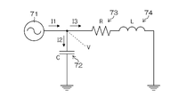
- FIG. 2 is a circuit diagram showing an equivalent circuit in which the ink flow path of the liquid ejection apparatus 10 shown in FIG. 1 is modeled as an acoustic circuit model.
- an alternating current source 71 corresponds to the pump 14.
- the electrostatic capacity C of the capacitor 72 corresponds to the capacity of the pump damper 16 (compliance component in terms of acoustic engineering), and the electric resistance R of the resistor 73 and the coil 74.
- the inductance L corresponds to the acoustic resistance and inertia component (inertance) of the tube 24 and the print head 30. Note that when a plurality of print heads 30 are connected, a value obtained by synthesizing the acoustic resistance and inertial component of each print head 30 is obtained.
- the ink flow rate from the pump 14 is I 1
- the ink flow rate to the pump damper 16 is I 2
- the ink flow rate to the tube 24 and the print head 30 is I 3.
- Equation 2 shows the frequency response to the ink flow rate (second-order low-pass filter), and it is necessary to sufficiently satisfy the vibration amplitude attenuation at the pulsation frequency of the pump 14 to be used.
- the pulsation frequency f p is preferably sufficiently greater than the cut-off frequency, for example, m ⁇ f c ⁇ f p ( m is a constant greater than 1) preferably satisfies the relationship.
- m 2 can be set.
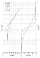
- FIG. 3 is a Bode diagram showing an example of the characteristics of the secondary low-pass filter.
- 3A is a Bode diagram showing the characteristics of the amplitude [unit: dB] with respect to the change of the pump pulsation frequency [unit: Hz]
- FIG. 3B is the pulsation frequency of the pump. It is a Bode diagram which shows the characteristic of the phase [unit: deg] with respect to the change of [unit: Hz].
- the cutoff frequency is 1 [Hz]
- FIG. 4 is a diagram schematically showing a liquid ejection apparatus having a circulation type print head.
- symbol is attached
- the liquid discharge device 40 includes a main tank 12, a pump (supply side pump) 14, a pump damper (supply side pump damper) 16, a tube (supply side tube) 24, and a recovery side tube. 42, a recovery-side pump damper 44, a recovery-side pump 52, and a plurality of circulation type print heads 60 (hereinafter referred to as print heads 60). Similar to the liquid ejecting apparatus 10, the number of print heads may be single or plural.
- the supply side tube 24 and the recovery side tube 42 are communicated with each other via a circulation type print head 60.
- the recovery side tube 42 is connected to a recovery side pump damper 44, and the recovery side pump damper 44 is connected to a recovery side pump 52.
- Ink is supplied to the print head 60 by the supply-side pump 14 in the same manner as the liquid ejection device 10.
- the ink that has not been ejected from the print head 60 is collected into the main tank 12 via the collection side tube 42 and the collection side pump damper 44 by the collection side pump 52 (second liquid pressure applying means).
- the recovery-side pump damper 44 (an example of a second pressure buffering unit) includes a liquid chamber 46 through which ink flows in and out, and an air chamber 50 that is opposed to the liquid chamber 46 with the flexible film 48 interposed therebetween. .
- the flexible film 48 is configured to be deformable or movable so as to change the volume of the liquid chamber.
- the recovery-side pump damper 44 sets the inside of the air chamber 50 to a predetermined pressure, so that the pressure fluctuation generated in the ink in the liquid chamber 46 is absorbed by the flexible film 48 and the air chamber 50, and the recovery side The pulsation of the pump 52 is reduced.
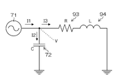
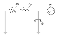
- FIG. 5 is a circuit diagram showing an equivalent circuit in which the ink flow path of the liquid ejection device 40 shown in FIG. 4 is modeled as an acoustic circuit model.
- an alternating current source 71 corresponds to the supply side pump 14
- an alternating current source 91 corresponds to the recovery side pump 52.
- the capacitance C 1 of the capacitor 72 and the capacitance C 2 of the capacitor 92 correspond to the capacities (compliance components in terms of acoustic engineering) of the supply-side pump damper 16 and the recovery-side pump damper 44, respectively.
- the electric resistance R of the resistor 93 and the inductance L of the coil 94 correspond to the acoustic resistance and inertance component of the supply side tube 24, the print head 60, and the recovery side tube 42, respectively.
- FIG. 6A is an equivalent circuit showing the frequency response of the pulsation of the supply-side pump 14
- FIG. 6B is an equivalent circuit showing the frequency response of the pulsation of the recovery-side pump 52.
- the pump pulsation frequencies f p1 and f p2 and the cut-off frequencies f c1 and f c2 only need to satisfy the relationship of f c ⁇ f p1 and f c ⁇ f p2 , respectively.
- ⁇ 1 > 1.0 may be satisfied, and if the relationship f c2 ⁇ f p2 ⁇ m ⁇ f c2 is satisfied, ⁇ 2 > It is sufficient to satisfy 1.0.
- FIG. 7 is a diagram illustrating an appearance of the design support apparatus 100 according to the present embodiment.
- the design support apparatus 100 is a personal computer, and includes a main body 110 for performing arithmetic processing, a monitor 120 for displaying arithmetic processing contents, and a keyboard 130 for inputting user instructions and character information.
- a removable recording medium 140 or the like in which an execution program is stored can be connected.
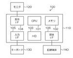
- FIG. 8 is a block diagram showing an electrical configuration of the design support apparatus 100.
- the main body 110 in addition to the CPU 101, the memory 102, and the hard disk 103, the main body 110 has a display interface 104 that outputs display information to the monitor 120, and an input interface that receives operation information from the keyboard 130. 105, a medium interface 106 for inputting / outputting control information for the recording medium 140 is provided.
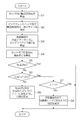
- FIG. 9 is a flowchart showing a design support method according to the present embodiment.
- an optimal ink supply channel is designed according to the frequency of the pump.
- a program for causing a computer to execute the process related to the design support method is stored in a recording medium (for example, a non-transitory recording medium) 140, and the design support apparatus 100 includes a main unit 110.
- This program is read from a recording medium 140 connected to a connector (not shown) and executed.
- This program may be stored in a hard disk built in the main unit 110, or supported by a wired or wireless LAN (Local Area Network), IrDA (InfraRed Data Association), Bluetooth (registered trademark), or the like. It may be an aspect that is read by the apparatus 100.
- LAN Local Area Network
- IrDA InfraRed Data Association
- Bluetooth registered trademark
- Step S1 From an expected ink consumption and circulation amount of the print head used to determine the rotational speed of the pump, to calculate the pulsation frequency f p of the pump associated therewith.
- Step S2 The primary design of the ink supply flow path from the print head and the pump to the print head is examined, and the determined primary design is input to the design support apparatus 100 (an example of a process for acquiring the primary design).
- Step S3 Based on the flow path parameters in the primary design of the supply flow path examined in step S2, the combined resistance R, the combined inertance L, and the compliance value C of the supply flow path are calculated (an example of an acquisition process and a calculation process).
- the flow path shape is very complicated and cannot be generalized.
- the combined resistance R, the combined inertance L, and the compliance value C may be derived using measured values.
- Step S4 L calculated in step S3, R, from the values and C, Equation 5 above, using Equation 6 to calculate the cut-off frequency f c and damping term ⁇ supply system of the ink.
- a cut-off frequency f c of the supply system of the ink calculated in the pulsation frequency f p and S4 of the pump calculated in step S1 is to determine whether it satisfies the relationship of f p ⁇ f c (determined Example of process).
- f p ⁇ f c the relationship satisfying f p ⁇ f c
- f c ⁇ f p determines whether they meet the ⁇ mf c cutlet zeta> 1 relationship.
- Step S6 if not satisfied f p ⁇ 2f c is to determine whether it satisfies f c ⁇ f p ⁇ 2f c . If this relationship is satisfied, the process proceeds to step S7, and if not, the process proceeds to step S9.
- Step S7 If f c ⁇ f p ⁇ 2f c is satisfied, it is next determined whether or not ⁇ > 1 is satisfied. If it is satisfied, pump pulsation can be reduced and resonance does not occur. Therefore, it is determined that there is no problem with the primary design print head and the peripheral supply path, and the process is terminated. If not, the process proceeds to step S8.
- Step S8 When f c ⁇ f p ⁇ 2f c and ⁇ ⁇ 1, resonance occurs and pulsation cannot be reduced. Therefore, the combined resistance R is increased from the primary design, and a warning that ⁇ > 1 is displayed on the monitor 120. The user can see the warning and change the flow path so that R becomes larger from the primary design.
- the value of the combined resistance R for ⁇ > 1 may be displayed.
- the user can change the primary design so that the combined resistance R becomes the displayed value.
- Step S9 In the case of f p ⁇ f c can not be reduced pulsation. Accordingly, a warning is issued to change at least one of the synthetic inertance L and the compliance value C so as to satisfy the relationship of f p ⁇ 2f c or the relationship of f c ⁇ f p ⁇ mf c and ⁇ > 1. Display on the monitor 120. The user can see this warning and change the flow path so that at least one value of L and C is changed from the primary design.
- At least one of the combined inertance L and the compliance value C for satisfying the relationship of f p ⁇ 2f c or the relationship of f c ⁇ f p ⁇ mf c and ⁇ > 1 may be displayed.
- the user can change the primary design so that the combined inertance L and the compliance value C become the displayed values.
- the liquid ejection apparatus 10 having the non-circular print head shown in FIG. 1 has been described, but the present invention can also be applied to the liquid supply apparatus having the supply side pump and the recovery side pump shown in FIG. In this case, the supply path and the recovery path can be optimized by performing the process shown in FIG. 9 for each pump using the equivalent circuit shown in FIG.
- the liquid ejection device is designed (an example of a design process), and the designed liquid ejection device is manufactured (an example of a method for manufacturing the liquid ejection device).
- the designed liquid ejection device is manufactured (an example of a method for manufacturing the liquid ejection device).
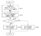
- the design support method according to the present embodiment will be described with reference to the flowchart shown in FIG.
- an optimal pump frequency is designed according to the ink supply flow path.
- the design support apparatus according to the present embodiment is the same as the design support apparatus 100 shown in FIGS.
- Step S11 Based on the print head determined by the design and the flow path parameters in the ink supply flow path, the combined resistance R, the combined inertance L, and the compliance value C are calculated.
- the above formulas 9 to 11 may be used to calculate these values.
- Step S12 Step S11 L calculated in, R, from the values and C, Equation 5 above, using Equation 6 to calculate the cut-off frequency f c and damping term ⁇ supply system of the ink.
- Step S13 Next, it is determined whether or not the attenuation term ⁇ calculated in step S12 satisfies ⁇ > 1. If satisfied, the process proceeds to step S14. If not satisfied, the process proceeds to step S15.
- Step S14 if it meets the zeta> 1 performs display that indicates selection of the pump to be f c ⁇ f p, the process ends.
- the user can know the appropriate pump pulsation frequency by viewing this display. It is also possible to display the frequency of a specific pump as the f c ⁇ f p.
- Step S15 If it is zeta ⁇ 1, in order to prevent the resonance, to display that indicates selection of the pump to be 2f c ⁇ f p, the process ends.
- the user can know the appropriate pump pulsation frequency by viewing this display. It is also possible to display the frequency of a specific pump as the 2f c ⁇ f p.
- the liquid ejecting apparatus 10 for feeding ink to the non-circular print head illustrated in FIG. 1 has been described.
- the present invention can also be applied to a liquid supply apparatus having a recovery side pump.
- the supply side pump and the recovery side pump can be optimized by performing the process shown in FIG. 10 for each ink path using the equivalent circuit shown in FIG.
- the liquid ejection device is designed (an example of a design process), and the designed liquid ejection device is manufactured (an example of a method for manufacturing the liquid ejection device).
- the designed liquid ejection device is manufactured (an example of a method for manufacturing the liquid ejection device).
- an attenuation term ⁇ 1 is obtained by increasing R by adding a filter or the like into the flow path (+ 2.66 ⁇ 10 8 [Pa ⁇ s / m 3 ]). Therefore, a pump with a pulsation frequency of 1 [Hz] can be used.
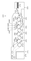
- FIG. 11 is a configuration diagram showing the overall configuration of an ink jet recording apparatus including the liquid ejection apparatus according to the present embodiment.
- the ink jet recording apparatus 200 shown in the figure forms an image on a recording surface of a recording medium 214 based on predetermined image data using an ink containing a color material and an aggregating treatment liquid having a function of aggregating the ink.
- This is a two-liquid aggregation type recording apparatus.
- the ink jet recording apparatus 200 includes a paper feeding unit 220, a processing liquid application unit 230, a drawing unit 240, a drying processing unit 250, a fixing processing unit 260, and a discharge unit 270.
- the drawing unit 240 is provided with a liquid ejection device.
- Transfer cylinders 232, 242, 252, and 262 are provided as means for delivering the recording medium 214 conveyed upstream of the processing liquid application unit 230, the drawing unit 240, the drying processing unit 250, and the fixing processing unit 260.
- drum-shaped impression cylinders 234, 244, 254, and 264 are provided as means for transporting the recording medium 214 while holding the recording medium 214 in each of the coating unit 230, the drawing unit 240, the drying processing unit 250, and the fixing processing unit 260. .
- the transfer cylinders 232 to 262 and the impression cylinders 234 to 264 are provided with grippers 280A and 280B that hold the front end portion of the recording medium 214 at predetermined positions on the outer peripheral surface.
- the structure in which the gripper 280A and the gripper 280B hold the leading end portion of the recording medium 214 and the structure in which the recording medium 214 is transferred between the gripper provided in another impression cylinder or the transfer cylinder are the same, and
- the gripper 280 ⁇ / b> A and the gripper 280 ⁇ / b> B are arranged at symmetrical positions moved by 180 ° in the rotation direction of the pressure drum 234 on the outer peripheral surface of the pressure drum 234.
- treatment liquid When the recording medium (sheet) 214 accommodated in the paper supply unit 220 is fed to the treatment liquid application unit 230, the aggregation process is performed on the recording surface of the recording medium 214 held on the outer peripheral surface of the impression cylinder 234.
- a liquid hereinafter simply referred to as “treatment liquid”.
- the “recording surface of the recording medium 214” is an outer surface in a state where the pressure drums 234 to 264 are held, and is a surface opposite to a surface held by the pressure drums 234 to 264.
- the recording medium 214 to which the aggregating treatment liquid is applied is sent to the drawing unit 240, and the drawing unit 240 applies the color ink to the area to which the aggregating treatment liquid is applied to form a desired image.
- the recording medium 214 on which the image of the color ink is formed is sent to the drying processing unit 250, where the drying processing unit 250 performs the drying processing, and after the drying processing, the recording medium 214 is sent to the fixing processing unit 260 to perform the fixing processing. Applied.
- the image formed on the recording medium 214 is fastened. In this manner, a desired image is formed on the recording surface of the recording medium 214, and after the image is fixed on the recording surface of the recording medium 214, the image is conveyed from the discharge unit 270 to the outside of the apparatus.
- each unit paper feeding unit 220, processing liquid coating unit 230, drawing unit 240, drying processing unit 250, fixing processing unit 260, discharge unit 270 of the inkjet recording apparatus 200 will be described in detail.
- the paper feeding unit 220 is provided with a paper feeding tray 222 and a feeding mechanism (not shown), and the recording medium 214 is configured to be fed one by one from the paper feeding tray 222.
- the recording medium 214 sent out from the paper feed tray 222 is positioned by a guide member (not shown) so as to be positioned at a gripper (not shown) of the transfer drum (paper feed drum) 232 and temporarily stops.
- a gripper (not shown) holds the leading end portion of the recording medium 214, and transfers the recording medium 214 to and from the gripper provided in the processing liquid cylinder 234.
- the processing liquid coating unit 230 includes a processing liquid drum (processing liquid drum) 234 that holds the recording medium 214 delivered from the paper feed cylinder 232 on the outer peripheral surface and transports the recording medium 214 in a predetermined transport direction, and a processing liquid. And a treatment liquid coating device 236 for applying a treatment liquid to the recording surface of the recording medium 214 held on the outer peripheral surface of the cylinder 234.
- processing liquid cylinder 234 When the processing liquid cylinder 234 is rotated counterclockwise in FIG. 11, the recording medium 214 is rotated and conveyed in the counterclockwise direction along the outer peripheral surface of the processing liquid cylinder 234.
- the processing liquid coating apparatus 236 shown in FIG. As a configuration example of the processing liquid coating device 236, a processing liquid container in which the processing liquid is stored, a pumping roller that is partially immersed in the processing liquid in the processing liquid container, and pumps up the processing liquid in the processing liquid container; An embodiment including an application roller (rubber roller) that moves the pumped processing liquid onto the recording medium 214 is exemplified.
- an application roller moving mechanism for moving the application roller in the vertical direction (the normal direction of the outer peripheral surface of the processing liquid cylinder 234) is provided, and the processing liquid is not applied to portions other than the recording medium 214.
- the grippers 280A and 280B that sandwich the leading end of the recording medium 214 are arranged so as not to protrude from the peripheral surface.
- the processing liquid applied to the recording medium 214 by the processing liquid coating apparatus 236 contains a color material aggregating agent that aggregates the color material (pigment) in the ink applied by the drawing unit 240, and the processing liquid is applied on the recording medium 214. And the ink come into contact with each other, the separation of the color material and the solvent in the ink is promoted.
- the treatment liquid coating device 236 is preferably applied while measuring the amount of the treatment liquid to be applied to the recording medium 214, and the film thickness of the treatment liquid on the recording medium 214 is an ink droplet ejected from the drawing unit 240. It is preferable to make it sufficiently smaller than the diameter.
- the drawing unit 240 holds a recording medium 214 and conveys the drawing cylinder (drawing drum) 244, a sheet pressing roller 246 for bringing the recording medium 214 into close contact with the drawing cylinder 244, and an ink jet for applying ink to the recording medium 214. Heads 248M, 248K, 248C, 248Y are provided.
- the basic structure of the drawing cylinder 244 is common to the processing liquid cylinder 234 described above.
- the sheet pressing roller 246 is a guide member for bringing the recording medium 214 into close contact with the outer peripheral surface of the drawing cylinder 244, faces the outer peripheral surface of the drawing cylinder 244, and transfers the recording medium 214 between the transfer cylinder 242 and the drawing cylinder 244. It is disposed downstream of the position in the transport direction of the recording medium 214 and upstream of the inkjet heads 248M, 248K, 248C, and 248Y in the transport direction of the recording medium 214.
- a paper floating detection sensor (not shown) is disposed between the paper pressing roller 246 and the uppermost ink jet head 248M in the conveyance direction of the recording medium 214.
- the sheet floating detection sensor detects the amount of floating immediately before the recording medium 214 enters immediately below the inkjet heads 248M, 248K, 248C, 248Y.
- the inkjet recording apparatus 200 shown in this example notifies that fact and interrupts the conveyance of the recording medium 214. It is configured as follows.
- the recording medium 214 transferred from the transfer cylinder 242 to the drawing cylinder 244 is pressed by the sheet pressing roller 246 when being rotated and conveyed with the front end held by a gripper (not shown), and the outer periphery of the drawing cylinder 244 Adhere to the surface. After the recording medium 214 is brought into close contact with the outer peripheral surface of the drawing cylinder 244 in this way, the recording medium 214 is sent to the print area immediately below the ink jet heads 248M, 248K, 248C, and 248Y without being lifted from the outer peripheral surface of the drawing cylinder 244. It is done.
- the inkjet heads 248M, 248K, 248C, and 248Y correspond to inks of four colors, magenta (M), black (K), cyan (C), and yellow (Y), respectively, and the rotation direction of the drawing cylinder 244 (see FIG. 11 (counterclockwise direction) in order from the upstream side, and the ink ejection surfaces (nozzle surfaces) of the inkjet heads 248M, 248K, 248C, and 248Y face the recording surface of the recording medium 214 held by the drawing cylinder 244. To be arranged.
- the “ink ejection surface (nozzle surface)” is a surface of the inkjet heads 248M, 248K, 248C, and 248Y that faces the recording surface of the recording medium 214, and is a nozzle that ejects ink to be described later (reference numeral in FIG. 13). 308 is shown).
- the recording surface of the recording medium 214 held on the outer peripheral surface of the drawing cylinder 244 and the nozzle surfaces of the inkjet heads 248M, 248K, 248C, and 248Y are substantially parallel. In such a manner, it is arranged to be inclined with respect to the horizontal plane.
- the inkjet heads 248M, 248K, 248C, and 248Y are full-line heads having a length corresponding to the maximum width of the image forming area in the recording medium 214 (the length in the direction orthogonal to the conveyance direction of the recording medium 214).
- the recording medium 214 is fixedly installed so as to extend in a direction orthogonal to the conveyance direction of the recording medium 214.
- Inkjet heads 248M, 248K, 248C, and 248Y are each supplied with ink from an ink supply device that will be described in detail later.
- nozzles for ejecting ink are formed in a matrix arrangement over the entire width of the image forming area of the recording medium 214.
- the image data is converted into the area where the aggregation processing liquid of the recording medium 214 is applied from the inkjet heads 248M, 248K, 248C, and 248Y. Based on this, ink of each color is ejected (droplet ejection).
- the drawing cylinder 244 of the drawing unit 240 is structurally separated from the processing liquid cylinder 234 of the processing liquid application unit 230, the processing liquid does not adhere to the inkjet heads 248M, 248K, 248C, and 248Y. In addition, the cause of abnormal ink ejection can be reduced.
- MKCY standard colors four colors
- the combination of ink colors and the number of colors is not limited to this embodiment, and light ink, dark ink, and special colors are used as necessary.
- Ink may be added.
- an inkjet head that discharges light-colored ink such as light cyan and light magenta, and the arrangement order of the color heads is not particularly limited.
- the drying processing unit 250 holds a drying drum (drying drum) 254 that holds and conveys the recording medium 214 after image formation, and a drying processing device 256 that performs a drying process for evaporating moisture (liquid component) on the recording medium 214. It has.
- the basic structure of the drying cylinder 254 is the same as that of the processing liquid cylinder 234 and the drawing cylinder 244 described above, and a description thereof is omitted here.
- the drying processing device 256 is a processing unit that is disposed at a position facing the outer peripheral surface of the drying drum 254 and evaporates moisture present in the recording medium 214.
- the liquid component (solvent component) of the ink and the liquid component (solvent component) of the processing liquid separated by the aggregation reaction between the processing liquid and the ink are placed on the recording medium 214. Since it remains, it is necessary to remove the liquid component.
- the drying processing device 256 performs a drying process for evaporating a liquid component existing on the recording medium 214 by heating with a heater, blowing with a fan, or a combination thereof, and a process for removing the liquid component on the recording medium 214. Part.
- the amount of heating and the amount of air supplied to the recording medium 214 are appropriately set according to parameters such as the amount of moisture remaining on the recording medium 214, the type of the recording medium 214, and the conveyance speed (drying processing time) of the recording medium 214. Is done.
- the drying cylinder 254 of the drying processing unit 250 is structurally separated from the drawing cylinder 244 of the drawing unit 240, and thus the inkjet heads 248M, 248K, 248C, 248Y. In this case, it is possible to reduce the cause of abnormal ink ejection due to drying of the head meniscus by heat or air blowing.
- the curvature of the drying drum 254 is preferably 0.002 (1 / mm) or more. In order to prevent the recording medium from being curved (curled) after the drying process, the curvature of the drying cylinder 254 is preferably 0.0033 (1 / mm) or less.
- a means for adjusting the surface temperature of the drying cylinder 254 may be provided, and the surface temperature may be adjusted to 50 ° C. or higher.
- a means for adjusting the surface temperature of the drying cylinder 254 for example, a built-in heater
- the surface temperature may be adjusted to 50 ° C. or higher.
- the upper limit of the surface temperature of the drying cylinder 254 is not particularly limited, but from the viewpoint of safety of maintenance work (such as prevention of burns due to high temperatures) such as cleaning of ink adhering to the surface of the drying cylinder 254. It is preferably set to 75 ° C. or lower (more preferably 60 ° C. or lower).
- the drying drum 254 configured in this manner is held on the outer peripheral surface of the recording medium 214 so that the recording surface of the recording medium 214 faces outward (that is, in a state where the recording surface of the recording medium 214 is convex). By performing the drying process while rotating and transporting, drying unevenness due to wrinkling and floating of the recording medium 214 is surely prevented.
- the fixing processing unit 260 includes a fixing drum (fixing drum) 264 that holds and conveys the recording medium 214, a heater 266 that performs heat treatment on the recording medium 214 on which an image is formed and liquid is removed, and the recording And a fixing roller 268 that presses the medium 214 from the recording surface side. Since the basic structure of the fixing cylinder 264 is common to the processing liquid cylinder 234, the drawing cylinder 244, and the drying cylinder 254, description thereof is omitted here.
- the heater 266 and the fixing roller 268 are disposed at positions facing the outer peripheral surface of the fixing cylinder 264, and are sequentially disposed from the upstream side in the rotation direction of the fixing cylinder 264 (counterclockwise direction in FIG. 11).
- the recording surface of the recording medium 214 is subjected to preheating processing by the heater 266 and fixing processing by the fixing roller 268.
- the heating temperature of the heater 266 is appropriately set according to the type of recording medium, the type of ink (the type of polymer particles contained in the ink), and the like. For example, a mode in which the glass transition temperature and the minimum film forming temperature of the polymer fine particles contained in the ink are considered.
- the fixing roller 268 is a roller member that heats and presses the dried ink to weld the self-dispersing polymer fine particles in the ink to form a film of the ink, and is configured to heat and press the recording medium 214.
- the Specifically, the fixing roller 268 is disposed so as to be in pressure contact with the fixing cylinder 264 and constitutes a nip roller with the fixing cylinder 264.
- the recording medium 214 is sandwiched between the fixing roller 268 and the fixing cylinder 264, and is nipped with a predetermined nip pressure, and fixing processing is performed.
- the fixing roller 268 is configured by a heating roller in which a halogen lamp is incorporated in a metal pipe such as aluminum having good thermal conductivity.
- a heating roller By heating the recording medium 214 with such a heating roller, when thermal energy equal to or higher than the glass transition temperature of the polymer fine particles contained in the ink is applied, the polymer fine particles melt to form a transparent film on the surface of the image. Is done.
- the surface hardness of the fixing roller 268 is preferably 71 ° or less. By making the surface of the fixing roller 268 softer, a tracking effect can be expected with respect to the unevenness of the recording medium 214 caused by cockling, and fixing unevenness due to the unevenness of the recording medium 214 is more effectively prevented. .
- an in-line sensor 282 is provided at the subsequent stage (downstream in the recording medium conveyance direction) of the processing area of the fixing processing unit 260.
- the inline sensor 282 is a sensor for reading an image formed on the recording medium 214 (or a check pattern formed in a blank area of the recording medium 214), and a CCD (Charge-Coupled Device) line sensor is preferably used.
- CCD Charge-Coupled Device
- the ink jet recording apparatus 200 shown in this example determines the presence / absence of ejection abnormality of the ink jet heads 248M, 248K, 248C, 248Y based on the reading result of the inline sensor 282.
- the inline sensor 282 may include a measuring unit for measuring a moisture amount, a surface temperature, a glossiness, and the like.
- parameters such as the processing temperature of the drying processing unit 250, the heating temperature of the fixing processing unit 260, and the pressure pressure are appropriately adjusted based on the reading results of the moisture content, the surface temperature, and the glossiness, and the temperature inside the apparatus.
- the control parameter is adjusted as appropriate in accordance with the change and the temperature change of each part.
- a discharge unit 270 is provided following the fixing processing unit 260.
- the discharge unit 270 includes an endless conveyance chain 274 wound around the stretching rollers 272A and 272B, and a discharge tray 276 that stores the recording medium 214 after image formation.
- the recording medium 214 after the fixing process sent out from the fixing processing unit 260 is transported by the transport chain 274 and discharged to the discharge tray 276.
- FIG. 12 is a schematic configuration diagram of the inkjet head 300, which is a diagram (a plan perspective view of the head) of the recording surface of the recording medium as viewed from the inkjet head 300.
- FIG. The head 300 shown in the figure forms a multi-head by connecting n head modules 302-i (i is an integer from 1 to n) in a line along the longitudinal direction of the head 300.
- Each head module 302-i is supported by head covers 304 and 306 from both sides of the head 300 in the short direction. It is also possible to configure a multi-head by arranging the head modules 302 in a staggered manner.
- the full line type head has a plurality of nozzles (FIG. 13) corresponding to the length (width) in the main scanning direction of the recording medium in the direction (main scanning direction) orthogonal to the moving direction (sub-scanning direction) of the recording medium. (Shown with reference numeral 308).
- An image can be formed on the entire surface of the recording medium by a so-called single pass image recording method in which the head 300 having such a structure and the recording medium are scanned only once relatively to perform image recording.
- the head module 302-i constituting the head 300 has a plane shape of a substantially parallelogram, and an overlap portion is provided between adjacent sub heads.
- the overlap portion is a connecting portion of the sub heads, and is formed by nozzles in which adjacent dots belong to different sub heads in the arrangement direction of the head modules 302-i.
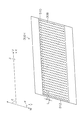
- FIG. 13 is a plan view showing the nozzle arrangement of the head module 302-i.
- each head module 302-i has a structure in which nozzles 308 are arranged two-dimensionally.
- a head including such a head module 302-i is a so-called matrix head.
- the head module 302-i illustrated in FIG. 13 includes a number of nozzles 308 along a column direction W that forms an angle ⁇ with respect to the sub-scanning direction Y and a row direction V that forms an angle ⁇ with respect to the main scanning direction X. It has an aligned structure, and the substantial nozzle arrangement density in the main scanning direction X is increased.
- nozzle groups (nozzle rows) arranged along the row direction V are denoted by reference numeral 310
- nozzle groups (nozzle rows) arranged along the column direction W are denoted by reference numeral 312. ing.
- nozzles 308 there is a configuration in which a plurality of nozzles 308 are arranged along the row direction along the main scanning direction X and the column direction oblique to the main scanning direction X.
- FIG. 14 is a cross-sectional view showing a three-dimensional configuration of a droplet ejection element (an ink chamber unit corresponding to one nozzle 308) for one channel serving as a recording element unit.
- a head 300 head module 302 of this example includes a nozzle plate 314 in which nozzles 308 are formed, and a flow path plate 320 in which flow paths such as a pressure chamber 316 and a common flow path 318 are formed. It has a structure in which etc. are laminated and joined.
- the nozzle plate 314 constitutes a nozzle surface 314A of the head 300, and a plurality of nozzles 308 communicating with the pressure chambers 316 are two-dimensionally formed.
- the flow path plate 320 constitutes a side wall portion of the pressure chamber 316 and a flow path forming a supply port 322 as a narrowed portion (most narrowed portion) of an individual supply path that guides ink from the common flow path 318 to the pressure chamber 316. It is a forming member.
- the flow path plate 320 has a structure in which one or a plurality of substrates are stacked, although it is illustrated schematically in FIG.
- the nozzle plate 314 and the flow path plate 320 can be processed into a required shape by a semiconductor manufacturing process using silicon as a material.
- the common flow path 318 communicates with an ink tank (not shown) as an ink supply source, and the ink supplied from the ink tank is supplied to each pressure chamber 316 via the common flow path 318.
- a diaphragm 324 constituting a part of the pressure chamber 316 (the top surface in FIG. 14) includes an individual electrode 326 and a lower electrode 328, and the piezoelectric body 330 is sandwiched between the individual electrode 326 and the lower electrode 328.
- a piezo actuator 332 having the above structure is joined.
- the diaphragm 324 is formed of a metal thin film or a metal oxide film, it functions as a common electrode corresponding to the lower electrode 328 of the piezo actuator 332.
- a lower electrode layer made of a conductive material such as metal is formed on the surface of the diaphragm member.
- the piezo actuator 332 When a drive voltage is applied to the individual electrode 326, the piezo actuator 332 is deformed to change the volume of the pressure chamber 316, and ink is ejected from the nozzle 308 due to the pressure change accompanying this. When the piezo actuator 332 returns to its original state after ink ejection, new ink is refilled into the pressure chamber 316 from the common flow path 318 through the supply port 322.
- the ink chamber unit having such a structure is latticed in a fixed arrangement pattern along a row direction V that forms an angle ⁇ with the main scanning direction X and a column direction W that forms an angle ⁇ with respect to the sub-scanning direction Y.
- the piezo actuator 332 is applied as a means for generating ink ejection force to be ejected from the nozzle 308 provided in the head 300.
- a heater is provided in the pressure chamber 316, and the pressure of film boiling caused by heating of the heater is used. It is also possible to apply a thermal method that ejects ink.
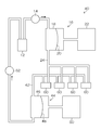
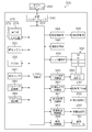
- FIG. 15 is a block diagram illustrating a schematic configuration of a control system of the inkjet recording apparatus 200.
- the inkjet recording apparatus 200 includes a communication interface 340, a system control unit 342, a conveyance control unit 344, an image processing unit 346, a head drive unit 348, and an image memory 350 and a ROM (Read Only Memory) 352.
- the communication interface 340 is an interface unit that receives image data sent from the host computer 354.
- the communication interface 340 may be a serial interface such as USB (Universal Serial ⁇ Bus) or a parallel interface such as Centronics.
- the communication interface 340 may include a buffer memory (not shown) for speeding up communication.
- the system control unit 342 includes a central processing unit (CPU) and its peripheral circuits.
- the system control unit 342 functions as a control device that controls the entire inkjet recording apparatus 200 according to a predetermined program, functions as a calculation device that performs various calculations, and further functions as a memory controller for the image memory 350 and the ROM 352. That is, the system control unit 342 controls each unit such as the communication interface 340 and the conveyance control unit 344, performs communication control with the host computer 354, read / write control of the image memory 350 and the ROM 352, and the above-described units. A control signal to be controlled is generated.
- CPU central processing unit
- Image data sent from the host computer 354 is taken into the ink jet recording apparatus 200 via the communication interface 340 and subjected to predetermined image processing by the image processing unit 346.
- the image processing unit 346 has a signal (image) processing function for performing various processing and correction processes for generating a print control signal from the image data, and supplies the generated print data to the head driving unit 348. It is a control unit. Necessary signal processing is performed in the image processing unit 346, and the ejection droplet amount (droplet ejection amount) and ejection timing of the head 300 are controlled via the head driving unit 348 based on the image data. Thereby, a desired dot size and dot arrangement are realized.
- the head driving unit 348 shown in FIG. 15 may include a feedback control system for keeping the driving conditions of the head 300 constant.
- the conveyance control unit 344 controls the conveyance timing and conveyance speed of the recording medium 214 (see FIG. 11) based on the print control signal generated by the image processing unit 346.
- 15 includes a motor for rotating the impression cylinders 234 to 264 in FIG. 11, a motor for rotating the transfer cylinders 232 to 62, a motor for the feeding mechanism of the recording medium 214 in the paper feeding section 220, and a discharge section 270.
- a motor for driving the tension roller 272A (272B) is included, and the conveyance control unit 344 functions as a controller for the motor.
- An image memory (primary storage memory) 350 functions as a primary storage unit that temporarily stores image data input via the communication interface 340, a development area for various programs stored in the ROM 352, and a calculation work area for the CPU. (For example, a work area of the image processing unit 346).
- a volatile memory Random Access Memory: RAM
- the ROM 352 stores a program executed by the CPU of the system control unit 342, various data necessary for controlling each unit of the apparatus, control parameters, and the like, and data is read and written through the system control unit 342.
- the ROM 352 is not limited to a memory made of a semiconductor element, and a magnetic medium such as a hard disk may be used. Alternatively, a removable storage medium that includes an external interface may be used.
- the ink jet recording apparatus 200 includes a processing liquid application control unit 360, a drying processing control unit 362, and a fixing processing control unit 364.
- the processing liquid application control unit 360, the drying processing control unit 362, and the fixing processing control unit 364 operate the processing liquid application unit 230, the drying processing unit 250, and the fixing processing unit 260, respectively, according to instructions from the system control unit 342. To control.
- the processing liquid application control unit 360 controls the processing liquid application timing and the application amount of the processing liquid based on the print data obtained from the image processing unit 346.
- the drying processing control unit 362 controls the timing of the drying processing in the drying processing apparatus 256, and also controls the processing temperature, the air flow rate, and the like.
- the fixing process control unit 364 controls the temperature of the heater 266 and the pressing of the fixing roller 268.
- the inline detection unit 466 including the inline sensor 282 illustrated in FIG. 11 is a processing block including a signal processing unit that performs predetermined signal processing such as nozzle removal, amplification, and waveform shaping on the read signal output from the inline sensor 282. .
- the system control unit 342 determines whether there is an ejection abnormality of the head 300 based on the detection signal obtained by the inline detection unit.
- the ink supply control unit 386 controls ink supply to the head 300 by the ink supply unit 388.
- the liquid ejection apparatuses 10 and 40 described above are applied to the head 300 and the ink supply unit 388 shown in FIG.
- the ink jet recording apparatus 200 shown in this example includes a user interface 370.
- the user interface 370 includes an input device 372 for an operator (user) to make various inputs and a display unit (display) 374.
- the input device 372 may employ various forms such as a keyboard, a mouse, a touch panel, and buttons.
- the operator can perform input of printing conditions, selection of image quality mode, input / editing of attached information, search of information, etc.
- Various information such as input contents and search results can be obtained. This can be confirmed through display on the display unit 374.
- the display unit 374 also functions as a means for displaying a warning such as an error message.
- the display unit 374 in FIG. 15 can be applied to a display as a notification unit in the control system illustrated in FIG.
- the deaeration control unit 368 controls the operation of the deaeration module 160 that performs a deaeration process on the liquid sent from the main tank (see FIG. 1) to the head 300.
- the parameter storage unit 380 stores various control parameters necessary for the operation of the inkjet recording apparatus 200.
- the system control unit 342 reads parameters necessary for control as appropriate and updates (rewrites) various parameters as necessary.
- the pressure sensor 381 includes a pressure detection element for measuring the pressure in the ink flow path, converts the measured pressure information into an electrical signal, and provides it to the system control unit 342.
- the system control unit 342 sends a command signal to the ink supply control unit 386 so as to correct the operation (rotational speed) of the pump included in the ink supply unit 388 based on the pressure information.
- the program storage unit 384 is a storage unit that stores a control program for operating the inkjet recording apparatus 200.
Landscapes
- Ink Jet (AREA)
- Particle Formation And Scattering Control In Inkjet Printers (AREA)
Priority Applications (2)
| Application Number | Priority Date | Filing Date | Title |
|---|---|---|---|
| EP13833925.4A EP2891558B1 (en) | 2012-08-31 | 2013-08-28 | Design assistance method and device |
| US14/634,660 US9289979B2 (en) | 2012-08-31 | 2015-02-27 | Assistance device, design assistance method and recording medium for liquid ejection device, method of manufacturing liquid ejection device, and image recording device |
Applications Claiming Priority (2)
| Application Number | Priority Date | Filing Date | Title |
|---|---|---|---|
| JP2012-191761 | 2012-08-31 | ||
| JP2012191761A JP5886164B2 (ja) | 2012-08-31 | 2012-08-31 | 液体吐出装置の設計支援装置、方法及びプログラム、液体吐出装置の製造方法 |
Related Child Applications (1)
| Application Number | Title | Priority Date | Filing Date |
|---|---|---|---|
| US14/634,660 Continuation US9289979B2 (en) | 2012-08-31 | 2015-02-27 | Assistance device, design assistance method and recording medium for liquid ejection device, method of manufacturing liquid ejection device, and image recording device |
Publications (1)
| Publication Number | Publication Date |
|---|---|
| WO2014034711A1 true WO2014034711A1 (ja) | 2014-03-06 |
Family
ID=50183519
Family Applications (1)
| Application Number | Title | Priority Date | Filing Date |
|---|---|---|---|
| PCT/JP2013/072982 Ceased WO2014034711A1 (ja) | 2012-08-31 | 2013-08-28 | 液体吐出装置の設計支援装置、方法及び記録媒体、液体吐出装置の製造方法ならびに画像記録装置 |
Country Status (4)
| Country | Link |
|---|---|
| US (1) | US9289979B2 (enExample) |
| EP (1) | EP2891558B1 (enExample) |
| JP (1) | JP5886164B2 (enExample) |
| WO (1) | WO2014034711A1 (enExample) |
Families Citing this family (12)
| Publication number | Priority date | Publication date | Assignee | Title |
|---|---|---|---|---|
| JP5877170B2 (ja) * | 2013-03-21 | 2016-03-02 | 富士フイルム株式会社 | インクジェット記録装置 |
| JP6477041B2 (ja) * | 2015-03-06 | 2019-03-06 | セイコーエプソン株式会社 | 液体噴射装置 |
| JPWO2016208533A1 (ja) * | 2015-06-26 | 2018-04-12 | 積水化学工業株式会社 | インクジェット印刷装置及び印刷方法 |
| EP3147124A1 (de) * | 2015-08-13 | 2017-03-29 | Heidelberger Druckmaschinen AG | Verfahren zum dämpfen von druckspitzen in einer leitung für tinte eines tintenstrahldruckers |
| JP6589474B2 (ja) * | 2015-09-08 | 2019-10-16 | ブラザー工業株式会社 | 液体吐出装置 |
| CN107020818B (zh) | 2016-02-02 | 2020-05-29 | 精工爱普生株式会社 | 液体喷射单元及其驱动方法以及液体喷射装置 |
| JP2017140760A (ja) | 2016-02-10 | 2017-08-17 | セイコーエプソン株式会社 | 液体噴射ヘッド、液体噴射装置、および、液体噴射装置の制御方法 |
| JP6734104B2 (ja) * | 2016-04-07 | 2020-08-05 | 東芝テック株式会社 | インクジェットプリンタ |
| JP6862741B2 (ja) | 2016-09-29 | 2021-04-21 | ブラザー工業株式会社 | 液体吐出装置及び液体供給ユニット |
| IT201600107827A1 (it) * | 2016-10-26 | 2018-04-26 | Jet Set S R L | Apparato di stampa e relativo procedimento |
| DE102018206464A1 (de) * | 2018-04-26 | 2019-10-31 | Heidelberger Druckmaschinen Ag | Verfahren zum Überprüfen einer Leitung für Tinte einer Tintendruckmaschine auf eine Störung |
| JP7486016B2 (ja) * | 2019-11-12 | 2024-05-17 | 株式会社リコー | 液体を吐出する装置及び液体を吐出する方法 |
Citations (4)
| Publication number | Priority date | Publication date | Assignee | Title |
|---|---|---|---|---|
| JPS60171163A (ja) | 1984-01-20 | 1985-09-04 | イング・チイ・オリベツチ・アンド・チイ・エス・ピー・ア | 噴射印刷装置 |
| JP2008304998A (ja) * | 2007-06-05 | 2008-12-18 | Canon Inc | 設計支援装置、設計支援方法並びにプログラム |
| JP2012030516A (ja) * | 2010-07-30 | 2012-02-16 | Fujifilm Corp | 液体供給装置及び液体吐出装置 |
| JP2012030515A (ja) * | 2010-07-30 | 2012-02-16 | Fujifilm Corp | 液体供給装置及び液体吐出装置並びに圧力制御方法 |
Family Cites Families (5)
| Publication number | Priority date | Publication date | Assignee | Title |
|---|---|---|---|---|
| US4413267A (en) * | 1981-12-18 | 1983-11-01 | Centronics Data Computer Corp. | Ink supply system for ink jet printing apparatus |
| JP4394119B2 (ja) * | 2003-05-02 | 2010-01-06 | ティーピーオー ディスプレイズ コーポレイション | プリントヘッドから放出されたインク滴の量を正確に制御する方法 |
| JP4920446B2 (ja) * | 2007-02-16 | 2012-04-18 | 富士フイルム株式会社 | 圧力調整装置および画像形成装置並びに圧力調整方法および液体残量検出方法 |
| JP5047108B2 (ja) * | 2008-09-30 | 2012-10-10 | 富士フイルム株式会社 | 液滴吐出装置 |
| WO2012030385A1 (en) * | 2010-08-30 | 2012-03-08 | Anajet, Inc. | Inkjet printer ink delivery system |
-
2012
- 2012-08-31 JP JP2012191761A patent/JP5886164B2/ja not_active Expired - Fee Related
-
2013
- 2013-08-28 WO PCT/JP2013/072982 patent/WO2014034711A1/ja not_active Ceased
- 2013-08-28 EP EP13833925.4A patent/EP2891558B1/en not_active Not-in-force
-
2015
- 2015-02-27 US US14/634,660 patent/US9289979B2/en active Active
Patent Citations (4)
| Publication number | Priority date | Publication date | Assignee | Title |
|---|---|---|---|---|
| JPS60171163A (ja) | 1984-01-20 | 1985-09-04 | イング・チイ・オリベツチ・アンド・チイ・エス・ピー・ア | 噴射印刷装置 |
| JP2008304998A (ja) * | 2007-06-05 | 2008-12-18 | Canon Inc | 設計支援装置、設計支援方法並びにプログラム |
| JP2012030516A (ja) * | 2010-07-30 | 2012-02-16 | Fujifilm Corp | 液体供給装置及び液体吐出装置 |
| JP2012030515A (ja) * | 2010-07-30 | 2012-02-16 | Fujifilm Corp | 液体供給装置及び液体吐出装置並びに圧力制御方法 |
Non-Patent Citations (1)
| Title |
|---|
| See also references of EP2891558A4 |
Also Published As
| Publication number | Publication date |
|---|---|
| US20150174897A1 (en) | 2015-06-25 |
| JP5886164B2 (ja) | 2016-03-16 |
| JP2014046577A (ja) | 2014-03-17 |
| EP2891558A1 (en) | 2015-07-08 |
| EP2891558A4 (en) | 2016-08-10 |
| EP2891558B1 (en) | 2017-09-27 |
| US9289979B2 (en) | 2016-03-22 |
Similar Documents
| Publication | Publication Date | Title |
|---|---|---|
| JP5886164B2 (ja) | 液体吐出装置の設計支援装置、方法及びプログラム、液体吐出装置の製造方法 | |
| JP5498307B2 (ja) | 液体供給装置及び液体吐出装置 | |
| JP5438622B2 (ja) | 液体供給装置及び液体吐出装置並びに圧力制御方法 | |
| JP5009229B2 (ja) | インクジェット記録装置 | |
| US8342673B2 (en) | Printing apparatus | |
| JP2015066842A (ja) | 圧力緩衝装置、液体流通装置、画像記録装置、及び液体流通装置の状態検出方法 | |
| JP4963572B2 (ja) | 液体供給装置、画像形成装置、及び液体供給方法 | |
| JP4855858B2 (ja) | 液体吐出ヘッド及び画像形成装置 | |
| JP2006256262A (ja) | 液体供給装置及び方法並びにインクジェット記録装置 | |
| US20080226377A1 (en) | Printer | |
| JP6754201B2 (ja) | 印刷装置および印刷用コンピュータプログラム | |
| JP6064650B2 (ja) | 液滴吐出装置 | |
| JP2015039781A (ja) | 払拭装置 | |
| JP2014128951A (ja) | 液滴吐出装置および画像形成装置 | |
| JP2014144611A (ja) | インクジェット記録装置及びインク充填方法 | |
| JP2012139980A (ja) | インク吐出装置、画像記録装置、インク吐出方法、及びプログラム | |
| JP2005104135A (ja) | 液体吐出装置及びインクジェット記録装置 | |
| JP6086289B2 (ja) | 液滴吐出ヘッドおよび画像形成装置 | |
| JP4902971B2 (ja) | 液体吐出ヘッド | |
| JP5393562B2 (ja) | インクジェット描画装置及びその設計方法並びに描画品質改善方法 | |
| US7810923B2 (en) | Ink jet printer | |
| JP2005262873A (ja) | 液吐出装置及び画像形成装置 | |
| JP4263676B2 (ja) | 液滴吐出ヘッド及びインクジェット記録装置 | |
| JP2006264170A (ja) | 液体搬送管および画像形成装置 | |
| JP2005271389A (ja) | 液滴吐出装置及び方法並びに画像形成装置 |
Legal Events
| Date | Code | Title | Description |
|---|---|---|---|
| 121 | Ep: the epo has been informed by wipo that ep was designated in this application |
Ref document number: 13833925 Country of ref document: EP Kind code of ref document: A1 |
|
| REEP | Request for entry into the european phase |
Ref document number: 2013833925 Country of ref document: EP |
|
| NENP | Non-entry into the national phase |
Ref country code: DE |