WO2014034491A1 - 電力伝送装置及び電力伝送方法 - Google Patents
電力伝送装置及び電力伝送方法 Download PDFInfo
- Publication number
- WO2014034491A1 WO2014034491A1 PCT/JP2013/072289 JP2013072289W WO2014034491A1 WO 2014034491 A1 WO2014034491 A1 WO 2014034491A1 JP 2013072289 W JP2013072289 W JP 2013072289W WO 2014034491 A1 WO2014034491 A1 WO 2014034491A1
- Authority
- WO
- WIPO (PCT)
- Prior art keywords
- power transmission
- power
- unit
- coil
- dielectric
- Prior art date
Links
Images


Classifications
-
- H—ELECTRICITY
- H02—GENERATION; CONVERSION OR DISTRIBUTION OF ELECTRIC POWER
- H02J—CIRCUIT ARRANGEMENTS OR SYSTEMS FOR SUPPLYING OR DISTRIBUTING ELECTRIC POWER; SYSTEMS FOR STORING ELECTRIC ENERGY
- H02J50/00—Circuit arrangements or systems for wireless supply or distribution of electric power
- H02J50/005—Mechanical details of housing or structure aiming to accommodate the power transfer means, e.g. mechanical integration of coils, antennas or transducers into emitting or receiving devices
-
- H—ELECTRICITY
- H01—ELECTRIC ELEMENTS
- H01F—MAGNETS; INDUCTANCES; TRANSFORMERS; SELECTION OF MATERIALS FOR THEIR MAGNETIC PROPERTIES
- H01F27/00—Details of transformers or inductances, in general
- H01F27/02—Casings
-
- H—ELECTRICITY
- H01—ELECTRIC ELEMENTS
- H01F—MAGNETS; INDUCTANCES; TRANSFORMERS; SELECTION OF MATERIALS FOR THEIR MAGNETIC PROPERTIES
- H01F38/00—Adaptations of transformers or inductances for specific applications or functions
- H01F38/14—Inductive couplings
-
- H—ELECTRICITY
- H02—GENERATION; CONVERSION OR DISTRIBUTION OF ELECTRIC POWER
- H02J—CIRCUIT ARRANGEMENTS OR SYSTEMS FOR SUPPLYING OR DISTRIBUTING ELECTRIC POWER; SYSTEMS FOR STORING ELECTRIC ENERGY
- H02J50/00—Circuit arrangements or systems for wireless supply or distribution of electric power
- H02J50/10—Circuit arrangements or systems for wireless supply or distribution of electric power using inductive coupling
- H02J50/12—Circuit arrangements or systems for wireless supply or distribution of electric power using inductive coupling of the resonant type
-
- H—ELECTRICITY
- H02—GENERATION; CONVERSION OR DISTRIBUTION OF ELECTRIC POWER
- H02J—CIRCUIT ARRANGEMENTS OR SYSTEMS FOR SUPPLYING OR DISTRIBUTING ELECTRIC POWER; SYSTEMS FOR STORING ELECTRIC ENERGY
- H02J50/00—Circuit arrangements or systems for wireless supply or distribution of electric power
- H02J50/70—Circuit arrangements or systems for wireless supply or distribution of electric power involving the reduction of electric, magnetic or electromagnetic leakage fields
-
- H—ELECTRICITY
- H04—ELECTRIC COMMUNICATION TECHNIQUE
- H04B—TRANSMISSION
- H04B13/00—Transmission systems characterised by the medium used for transmission, not provided for in groups H04B3/00 - H04B11/00
- H04B13/02—Transmission systems in which the medium consists of the earth or a large mass of water thereon, e.g. earth telegraphy
Definitions
- the present invention relates to a power transmission device and a power transmission method.
- a coil having a plurality of windings is used as a means for transmitting and receiving power wirelessly.
- a magnetic flux that links the coil is generated.
- the magnetic flux is linked to the coil of the power receiving unit, thereby generating an induced current in the coil of the power receiving unit, and power is transmitted.
- Patent Document 1 discloses a technology for performing communication between a terminal device body and a removable electronic device such as a memory card using a wireless millimeter wave signal.
- Patent Document 2 discloses a technology that uses a magnetic material to improve the inductance values of the power transmission unit and the power reception unit to increase the distance of power transmission.
- Patent Document 3 discloses a technique for improving the mutual inductance between the power transmission unit and the power reception unit by using a coil having a high Q value to resonate at the same frequency (magnetic field resonance), thereby increasing the distance. Yes.
- the above-described long-distance technology can obtain only a small power transmission efficiency even if the long-distance technology in the atmosphere is applied to seawater.
- This is based on the fact that the electrical conductivity and the dielectric constant are significantly different between air and seawater, and the mechanism of power transmission in the medium is different between power transmission in the atmosphere and power transmission in seawater.
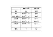
- the electrical conductivity of air is 0 S / m and the relative dielectric constant is about 1
- the electrical conductivity of seawater is about 4 S / m and the relative dielectric constant is about 81.
- the cause of the decrease in power transmission efficiency mainly consists of a conductor loss in the coil, a matching loss between the power transmission unit and the power reception unit, a reflection loss such as a leakage magnetic flux, and a radiation loss.
- this radiation loss is effectively suppressed by using a non-radiation phenomenon in which energy is accumulated in the vicinity of the power transmission / reception unit using a coil having a high Q value.
- seawater since the seawater has a certain conductivity, a loss occurs when energy propagates through the medium.
- the cause of this energy loss is based on the electrical conductivity in the seawater and the electric field generated in the seawater. That is, a loss occurs when a potential gradient proportional to the product of the conductivity and the electric field is generated in seawater.
- seawater since seawater has high conductivity, when energy is sent non-directionally from the power transmission unit in the seawater, energy that disappears without reaching the opposite power reception unit increases. Therefore, in order to efficiently transmit power in seawater, it is necessary to provide directivity that connects the opposing coil surfaces to form a flow of energy substantially perpendicular to the coil surfaces.
- the millimeter wave signal shown in Patent Document 1 is particularly difficult to transmit the millimeter wave signal shown in Patent Document 1 in a good conductor medium such as seawater.
- a good conductor medium such as seawater.
- the attenuation distance in seawater is 100 ⁇ m or less, so that it is impossible to propagate 10 cm or more in seawater.
- various media as shown in the table of FIG. 27 also have relatively high electrical conductivity and relative dielectric constant. Therefore, the same problem may occur when trying to transmit power wirelessly in such a medium as well as in seawater.
- the present invention provides a power transmission device and a power transmission method that solve the above-described problems.
- the present invention has been made to solve the above-described problems, and is a power transmission device that wirelessly transmits power in a good conductor medium, and includes a power transmission unit that wirelessly transmits power, and a power transmission unit that is transmitted from the power transmission unit.
- a power receiving unit that transmits wireless power, and the power transmitting unit and the power receiving unit include a power transmission coil and an inclusion unit that includes a dielectric covering the power transmission coil.
- a power transmission device that performs power transmission by resonating at a frequency determined by an impedance, an impedance of the power receiving unit, and an impedance of the good conductor medium.
- the present invention is also a power transmission method for wirelessly transmitting power in a good conductor medium, wherein the inclusion section covers the power transmission coil with a dielectric, the power transmission section transmits the power wirelessly, and the power reception section
- An electric power transmission method that transmits the transmitted wireless power and resonates at a frequency determined by the impedance of the power transmission unit, the impedance of the power reception unit, and the impedance of the good conductor medium. is there.
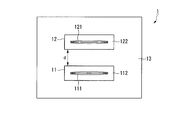
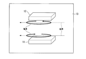
- FIG. 1 is a diagram illustrating a configuration of a power transmission device according to the first embodiment.
- the power transmission device 1 includes a power transmission unit 11 and a power reception unit 12.
- the power transmission unit 11 and the power reception unit 12 are covered with a good conductor medium 13.
- the power transmission unit 11 includes a power transmission coil 111 and a power transmission side inclusion unit 112 made of a dielectric covering the power transmission coil 111.
- the power reception unit 12 includes a power reception coil 121 and a power reception side inclusion unit 122.
- the power transmission coil 111 and the power reception coil 121 are formed by winding a conductor such as a copper wire a plurality of times. Generally, a helical coil, a spiral coil, or the like is used. However, in the present embodiment, the present invention is not limited thereto. None happen.
- the power transmission unit and the power reception unit in the power transmission apparatus are collectively referred to as a power transmission unit.
- the power transmission coil and the power reception coil are collectively referred to as a power transmission coil.
- the power transmission unit may have a function as a power reception unit, and the power reception unit may have a function as a power transmission unit.
- the power transmission unit and the power reception unit may have the same configuration.
- the power transmission side inclusion unit 112 and the power reception side inclusion unit 122 are made of a dielectric material having a relative dielectric constant of about 2 to 10 and a dielectric loss tangent of 0.01 or less, such as polyethylene, polyimide, polyamide, fluororesin, and acrylic. To do.
- each embodiment demonstrates on the assumption that a good conductor medium is seawater, this invention is not limited to this.
- a material having a conductivity of 1 ⁇ 10 ⁇ 4 S / m or more and a relative dielectric constant greater than 1 may be used, such as rivers, fresh water, tap water, soil, and concrete shown in the table of FIG. .
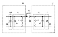
- FIG. 2 shows an equivalent circuit when the wireless power transmitted from the power transmission unit 11 propagates to the power reception unit 12.
- FIG. 2 is an equivalent circuit diagram for the wireless power when the wireless power propagates from the power transmitting unit 11 to the power receiving unit 12.
- the power transmission unit 11 and the power reception unit 12 further include a power transmission side impedance adjustment unit 113 and a power reception side impedance adjustment unit 123 that adjust the impedance of the power transmission coil 111 or the power reception coil 121.
- the impedance of the power transmission coil 111 in the power transmission unit 11 mainly includes an inductive component (inductance component) L1 and a capacitance component (capacitance component) C1, which are the shape of the coil, the number of turns, and the thickness of the copper wire.
- the impedance of the power receiving coil 121 in the power receiving unit 12 also includes an inductive component L2 and a capacitive component C2.
- the power transmission side impedance adjustment unit and the power reception side impedance adjustment unit are collectively referred to simply as an impedance adjustment unit.
- L3 is a mutual inductance component in the power transmission coil 111 and the power reception coil 121
- C3 is a capacitance component composed of the power transmission unit 11, the power reception unit 12, and the good conductor medium 13.
- a variable capacitance component C1 ′ is added as the power transmission side impedance adjustment unit 113, and a variable capacitance capacitance component C2 ′ is added as the power reception side impedance adjustment unit 123. Adjustments can be made to achieve consistency. In this way, even if the positional relationship between the power transmitting unit 11 and the power receiving unit 12 changes during power transmission and the value of C3 fluctuates, if C1 ′ and C2 ′ are appropriately adjusted to compensate for the fluctuation, And stable power can be supplied.
- a varactor diode (variable capacitance diode) can be used for the capacitance variable portion, and a plurality of capacitances can be combined with a switch transistor.
- the combined capacitance component of the capacitance component of the power transmission coil 111 itself and the variable capacitance capacitance component is again referred to as C1, and this is the capacitance component C1 constituting the impedance of the power transmission unit 11. Will be described.
- the combined capacity component of the power receiving coil 121 itself and the variable capacity capacity component is referred to as C2, and this will be described as the capacity component C2 constituting the impedance of the power receiving unit 12.
- the capacitance component C1 that constitutes the impedance of the power transmission unit 11 the capacitance component C2 that constitutes the impedance of the power reception unit 12, the power transmission unit 11, and the power reception unit 12
- the predetermined condition is satisfied with respect to the capacitance component C3 formed by the good conductor medium 13 existing therebetween and the distance d between the power transmission unit and the power reception unit, particularly high power transmission efficiency can be obtained.
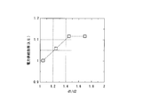
- FIG. 3 is a graph showing the influence of the capacitance components of the power transmission unit 11 and the power reception unit 12 and the capacitance component generated between the power transmission and reception units on the power transmission efficiency. According to the graph shown in FIG. 3, it can be seen that C1 [pF], C2 [pF], C3 [pF], and d [cm] can obtain particularly high power transmission efficiency when the following conditions are satisfied.
- the power transmission coil 111 and the power reception coil 121 are about 10 cm 2 to 30 cm 2 , and the distance d between the power transmission unit 11 and the power reception unit 12 is about 5 cm to 30 cm.
- Condition (1) can be satisfied under conditions.
- the power ratio is particularly high when the dimensional ratio between the power transmission coil 111 and the power transmission side inclusion portion 112 and the dimensional ratio between the power reception coil 121 and the power reception side inclusion portion 122 satisfy predetermined conditions. Transmission efficiency can be obtained.
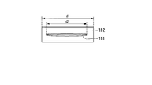
- FIG. 4A is a graph showing the influence of the outer diameter of the power transmission coil 111 and the dimensional ratio of the power transmission side inclusion section 112 on the power transmission efficiency.
- the relationship between the size d1 in the direction along the coil surface of the power transmission side inclusion portion 112 and the outer diameter d2 (FIG. 4B) of the power transmission coil 111 is such that the ratio d1 / d2 is 1.2 or more.
- the ratio d1 / d2 is preferably 1.4 or more.
- an AC power source (not shown) outputs AC power at a predetermined frequency.
- the output AC power is supplied to the power transmission coil 111, and the power transmission coil 111 sends the AC power to the outside (the good conductor medium 13) as electromagnetic energy.
- the power receiving unit 12 sends the transmitted electromagnetic energy in the power receiving coil 121.
- the power transmission side impedance adjustment unit 113 and the power reception side impedance adjustment unit 123 are adjusted so that the combined impedance of the power transmission unit 11, the power reception unit 12, and the good conductor medium 13 resonates at the frequency of the transmission power.
- the power sent by the power receiving coil 121 is supplied to a target load (for example, a battery), and power transmission is completed.
- the power transmitted to the power receiving coil 121 is maximized by resonating with the combined impedance of the power transmission unit 11, the power reception unit 12, and the good conductor medium 13. it can. Further, the power transmission side inclusion unit 112 and the power reception side inclusion unit 122 suppress the spread of the electric field into the good conductor medium 13, thereby minimizing the electromagnetic energy that diffuses and disappears in the good conductor medium 13. .
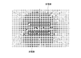
- FIG. 5 is a diagram showing an electric field vector and a magnetic field vector in the power transmission device 1 according to the first embodiment
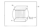
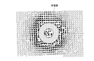
- FIG. 6 is a diagram showing a pointing vector (energy flow) generated based on the electric field vector and the magnetic field vector.
- FIGS. 5 and 6 are schematic diagrams showing simulation results of the electric field and the magnetic field generated between the power transmission unit 11 and the power reception unit 12 during power transmission.
- the electric field and the magnetic field can be made substantially parallel to the coil surface.
- a pointing vector (electromagnetic energy flow) from the power transmission unit 11 to the power reception unit 12 can be generated substantially vertically.
- the power transmission device 1 As described above, according to the power transmission device 1 according to the first embodiment, even when the power transmission unit 11 and the power reception unit 12 are in a relatively far field, electromagnetic energy that diffuses and disappears in a good conductor medium is minimized. As a result, it is possible to extend the distance by wireless power transmission in a good conductor medium such as seawater.
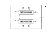
- FIG. 7 is a diagram showing the configuration of the power transmission device according to the second embodiment of the present invention.
- the power transmission device 2 includes a power transmission unit 21 and a power reception unit 22.
- the power transmission unit 21 and the power reception unit 22 are covered with a good conductor medium 23.
- the power transmission unit 21 includes a power transmission coil 211, a first power transmission side inclusion unit 212 made of a first dielectric covering the power transmission coil 211, and a second dielectric made of a second dielectric covering the first power transmission side inclusion unit 212.
- a power transmission side inclusion unit 213 is provided.
- the power reception unit 22 includes a power reception coil 221, a first power reception side inclusion unit 222, and a second power reception side inclusion unit 223.
- the first power transmission side inclusion part and the first power reception side inclusion part are collectively referred to as a first inclusion part
- the second power transmission side inclusion part and the second power reception side inclusion part are collectively referred to as a second inclusion part.
- the first power transmission side inclusion section 212, the second power transmission side inclusion section 213, the first power reception side inclusion section 222, and the second power reception side inclusion section 223 are, for example, specific dielectrics such as polyethylene, polyimide, polyamide, fluororesin, and acrylic. It is made of a dielectric having a ratio of about 2 to 10 and a dielectric loss tangent of 0.01 or less.
- the relative dielectric constant of the first dielectric constituting the first power transmission side inclusion unit 212 and the relative dielectric constant of the second dielectric constituting the second power transmission side inclusion unit 213 The rates may be different or the same. Also, the dielectric loss tangent of the first dielectric constituting the first power transmission side inclusion 212 and the dielectric loss tangent of the second dielectric constituting the second power transmission side inclusion 213 may be different or the same. Also good. The same applies to the first dielectric constituting the first power receiving side inclusion 222 and the second dielectric constituting the second power receiving side inclusion 223.
- FIG. 7 which shows the structure of the electric power transmission apparatus 2
- both the power transmission part 21 and the power receiving part 22 are described as a structure which has a 1st inclusion part and a 2nd inclusion part
- 2nd Embodiment Only one of the power transmission unit 21 and the power reception unit 22 may have a structure including a first inclusion unit and a second inclusion unit.
- the power transmission device 2 of the present embodiment may also include the impedance adjustment unit described in the first embodiment.
- the dielectric loss tangent of each dielectric constituting the first power transmission side inclusion unit 212 and the second power transmission side inclusion unit 213 satisfies a predetermined condition, it is even higher. Power transmission efficiency can be obtained.
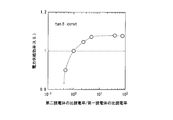
- FIG. 8 is a graph showing the influence of the ratio of the dielectric tangent of the first dielectric and the dielectric tangent of the second dielectric on the power transmission efficiency.
- FIG. 8 shows that a higher power transmission efficiency can be obtained by making the dielectric loss tangent of the second dielectric larger than that of the first dielectric. This has the effect of suppressing the expansion of the electric field to the good conductor medium 23 by the second dielectric constituting the second power transmission side inclusion 213 (second power reception side inclusion 223), and the first power transmission side inclusion Based on the effect that the dielectric loss in the vicinity of the power transmission coil 211 (power reception coil 221) can be reduced by reducing the dielectric loss tangent of the first dielectric constituting 212 (first power reception side inclusion portion 222). It is.
- the dielectric constant of each dielectric that constitutes the first power transmission side inclusion unit 212 and the second power transmission side inclusion unit 213 satisfies a predetermined condition, it is even higher. Power transmission efficiency can be obtained.
- FIG. 9 is a graph showing the influence of the relative permittivity of the first dielectric and the relative permittivity of the second dielectric on the power transmission efficiency.
- FIG. 9 shows that higher power transmission efficiency can be obtained by making the relative dielectric constant of the second dielectric larger than that of the first dielectric.
- an AC power source (not shown) outputs AC power at a predetermined frequency.
- the output AC power is supplied to the power transmission coil 211, and the power transmission coil 211 sends the AC power to the outside (the good conductor medium 23) as electromagnetic energy.
- the power receiving unit 12 sends the sent electromagnetic energy through the power receiving coil 221.
- the combined impedances of the power transmission unit 21, the power reception unit 22, and the good conductor medium 23 are adjusted so as to resonate at the frequency of the transmission power.
- the power sent by the power receiving coil 221 is supplied to a target load (for example, a battery), and the power transmission is completed.
- the power transmitted to the power receiving coil 221 can be maximized by resonating with the combined impedance of the power transmitting unit 21, the power receiving unit 22, and the good conductor medium 23. it can.
- the second power transmission side inclusion unit 213 and the second power reception side inclusion unit 223 suppress the expansion of the electric field into the good conductor medium 23, thereby minimizing the electromagnetic energy that diffuses and disappears in the good conductor medium 13. There is an effect to suppress.
- the first power transmission side inclusion unit 212 and the first power reception side inclusion unit 222 have an effect of reducing dielectric loss in the vicinity of the power transmission coil 211 and the power reception coil 221.
- the power transmission device 2 according to the second embodiment can obtain high power transmission efficiency similarly to the power transmission device 1 according to the first embodiment.
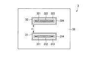
- FIG. 10 is a diagram showing the configuration of the power transmission device according to the third embodiment of the present invention.
- the power transmission device 3 includes a power transmission unit 31 and a power reception unit 32.
- the power transmission unit 31 and the power reception unit 32 are covered with a good conductor medium 33.
- the power transmission unit 31 includes a power transmission coil 311, a first power transmission side inclusion unit 312 made of a first dielectric covering the power transmission coil 311, and a second power transmission side inclusion made of a second dielectric covering the first power transmission side inclusion unit 312.
- a third power transmission side inclusion portion 314 made of a third dielectric covering the portion 313 and the second power transmission side inclusion portion 313.
- the power reception unit 32 includes a power reception coil 321, a first power reception side inclusion unit 322, a second power reception side inclusion unit 323, and a third power reception side inclusion unit 324.
- the third power transmission side inclusion part and the third power reception side inclusion part are collectively referred to as a covering part.
- the first power transmission side inclusion unit 312, the third power transmission side inclusion unit 314, the first power reception side inclusion unit 322, and the third power reception side inclusion unit 324 are, for example, specific dielectrics such as polyethylene, polyimide, polyamide, fluororesin, and acrylic. It is made of a dielectric having a ratio of about 2 to 10 and a dielectric loss tangent of 0.01 or less.
- the 2nd power transmission side inclusion part 313 and the 2nd power reception side inclusion part 323 are equal to the specific gravity of the good conductor medium 33 (seawater), and consist of liquids (for example, pure water, distilled water) with low electrical conductivity.
- the 2nd power transmission side inclusion part 313 and the 2nd power reception side inclusion part 323 can work as neutral buoyancy in the good conductor medium 33 (in seawater).
- the second power transmission side inclusion unit 313 or the second power reception side inclusion unit 323 can be made to have a neutral buoyancy, for example, when the power transmission device 3 is floated and submerged in seawater, it is necessary to provide a mechanism for adjusting the specific gravity. Therefore, the cost can be reduced.
- the 3rd power transmission side inclusion part 314 and the 3rd power reception side inclusion part 324 which consist of 3rd dielectrics physically confine the 2nd power transmission side inclusion part 313 and the 2nd power reception side inclusion part 323 which are liquids.
- the relative dielectric constant of the third dielectric constituting the third power transmission side inclusion portion 314 may be different or the same.
- the dielectric loss tangent of the first dielectric constituting the first power transmission side inclusion unit 312, the dielectric loss tangent of the second dielectric constituting the second power transmission side inclusion unit 313, and the third power transmission side inclusion unit 314 are configured.
- the dielectric loss tangents of the third dielectric may be different or the same. The same applies to the first dielectric constituting the first power receiving side inclusion 322, the second dielectric constituting the second power receiving side inclusion 323, and the third dielectric constituting the third power receiving side inclusion 324. is there.
- both the power transmission part 31 and the power receiving part 32 are described as a structure which has the 1st inclusion part, the 2nd inclusion part, and the 3rd inclusion part which were demonstrated above.
- only one of the power transmission unit 31 and the power reception unit 32 may have a structure including the first inclusion unit, the second inclusion unit, and the third inclusion unit.
- the power transmission device 3 according to the third embodiment may also include the impedance adjustment unit described in the first embodiment.
- an AC power source (not shown) outputs AC power at a predetermined frequency.
- the output AC power is supplied to the power transmission coil 311, and the power transmission coil 311 sends the AC power to the outside (good conductor medium 33) as electromagnetic energy.
- the power receiving unit 32 sends the sent electromagnetic energy through the power receiving coil 321.
- the combined impedances of the power transmission unit 31, the power reception unit 32, and the good conductor medium 33 are adjusted so as to resonate at the frequency of the transmission power.
- the power sent by the power receiving coil 321 is supplied to a target load (for example, a battery), and power transmission is completed.
- the power transmitted to the power receiving coil 321 can be maximized by resonating with the combined impedance of the power transmitting unit 31, the power receiving unit 32, and the good conductor medium 33. it can.
- the second power transmission side inclusion unit 313 and the second power reception side inclusion unit 323 suppress the spread of the electric field into the good conductor medium 33, thereby minimizing the electromagnetic energy that diffuses and disappears in the good conductor medium 33. There is an effect to suppress.
- the first power transmission side inclusion unit 312 and the first power reception side inclusion unit 322 have an effect of reducing dielectric loss in the vicinity of the power transmission coil 311 and the power reception coil 321.
- the power transmission device 3 according to the third embodiment includes the third power transmission side inclusion unit 314 and the third power reception side inclusion unit 324, the second power transmission side inclusion unit 313 and the second power reception side inclusion are included.
- a liquid for example, pure water or distilled water
- the power transmission unit 31 and the power reception unit 32 can make the second power transmission side inclusion unit 313 and the second power reception side inclusion unit 323 work as neutral buoyancy.
- the power transmission device 3 according to the third embodiment does not need a special specific gravity adjustment mechanism, and thus is equivalent to the power transmission device 1 according to the first embodiment and the power transmission device 2 according to the second embodiment.
- the cost can be reduced.
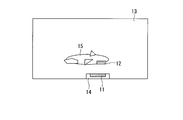
- FIG. 11 shows a first example of the third embodiment.
- the power transmission unit 11 of the power transmission device 1 is provided in the power supply source 14, and the power reception unit 12 is provided in the submarine 15.
- the present invention it is possible to stably supply power even when a tidal current occurs and the positional relationship between the power supply source 14 and the submersible craft 15 changes.
- FIG. 12 shows a second example of the third embodiment.
- the power transmission unit 11 of the power transmission device 1 is provided in the submersible craft 16, and the power receiving unit 12 is provided in the submersible craft 17.
- the present invention it is possible to stably supply power even when a tidal current occurs and the positional relationship between the submersible craft 16 and the submersible craft 17 changes.
- the submersible craft 16 and the submersible craft 17 can supply power in both directions by using the power transmission unit 11 as a power reception unit and the power reception unit 12 as a power transmission unit.
- the submersible craft 16 and the submersible craft 17 may include both the power transmission unit 11 and the power reception unit 12.
- the submersible craft 17 provided with the power receiving unit 12 may be a ship or a sensor device laid on the seabed.
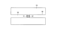
- FIG. 13 shows a third example of the third embodiment.
- the power transmission unit 11 is provided at the connection portion of the power cable 18, and the power reception unit 12 is provided at the connection portion of the power cable 19.
- the power cable 18 and the power cable 19 can supply power bidirectionally by using the power transmission unit 11 as a power reception unit and the power reception unit 12 as a power transmission unit. Further, the power cable 18 and the power cable 19 may include both the power transmission unit 11 and the power reception unit 12.
- a function of transmitting information wirelessly may be installed in the power transmission unit 11 and the power reception unit 12.
- the power transmission unit 11 as a transmitter and the power reception unit 12 as a receiver, it is not necessary to separately provide a mechanism for wireless communication, so that a small and low-cost system can be obtained.
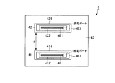
- FIG. 14 is a model diagram for simulation for demonstrating the effect of the power transmission device 4 according to the third embodiment.
- the power transmission device 4 includes a power transmission unit 41 and a power reception unit 42.
- the power transmission unit 41 and the power reception unit 42 are covered with seawater 43 as a good conductor medium.
- the power transmission unit 41 includes a helical coil (power transmission coil) 411, an internal dielectric (first power transmission side inclusion) 412, an external dielectric (second power transmission side inclusion) 413, and a covering dielectric (third power transmission side inclusion). Part) 414.
- the power receiving unit 42 includes a helical coil (power receiving coil) 421, an internal dielectric (first power receiving side including portion) 422, an external dielectric (second power receiving side including portion) 423, and a covering dielectric (third power receiving side included). Part) 424.
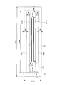
- FIG. 15 is a schematic top view of the power transmission unit 41 in the first example of the third embodiment.
- the helical coil 411 shown in FIG. 15 has a structure in which two single-layer coils each having 29 windings of an outer diameter of 220 mm and an inner diameter of 100 mm are opposed to each other with a distance of 3 mm. AC power is applied from the feed port to the opposed helical coil.
- the inner dielectric 412 is made of fluororesin
- the covering dielectric 414 is made of acrylic.
- the size of the covering dielectric 414 is 255 mm in length, 255 mm in width, and 19 mm in height.
- the resonance frequency of the power transmission device 4 is about 1 MHz.
- the ratio d1 / d2 of the outer coil size d2 and the coated dielectric size d1 is 1.16, which is larger than 1, sufficiently high power transmission efficiency can be obtained. ing. However, if the ratio of d1 / d2 is larger than 1.16, higher power transmission efficiency can be obtained.
- the power reception unit 42 has the same configuration as the power transmission unit 41. However, the configuration shown here is an example, and the same effect can be obtained even if the power transmission unit 41 and the power reception unit 42 are not the same configuration.
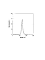
- FIG. 16 is a graph showing a simulation result of power transmission efficiency in the first example of the third embodiment.
- the distance d between the power transmission unit 41 and the power reception unit 42 is 10 cm and the power transmission efficiency is simulated in seawater, the frequency f of the transmission power is 40% or more near 1 MHz as shown in FIG. High power transmission efficiency could be obtained.
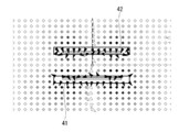
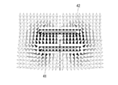
- FIGS. 17A and 17B and FIGS. 18A and 18B are diagrams respectively showing an electric field vector and a magnetic field vector in the vicinity of the power transmission unit 41 and the power reception unit 42 in the first example of the third embodiment.
- FIGS. It is a figure which shows the pointing vector of the power transmission part 41 in this Example, and the power receiving part 42 vicinity. The result of performing a detailed three-dimensional electromagnetic field simulation on the electric field, magnetic field, and pointing vector in the power transmission device 4 according to the above-described embodiment will be described with reference to FIGS. 17A to 19B.
- the flow of the electric field rotates along a plane parallel to the coil surface, and as shown in FIGS.
- a flow is generated radially along a plane parallel to the coil surface. Based on the flow of the electric and magnetic fields, a pointing vector (energy flow) is generated in a direction substantially perpendicular to the coil surface (FIGS. 19A and 19B).
- a pointing vector energy flow
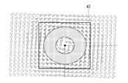
- FIGS. 20A and 20B are diagrams illustrating pointing vectors in the atmosphere of the power transmission device 4 according to the first example of the third embodiment.
- the result of having simulated the power transmission part 41 and the power reception part 42 of the power transmission device 4 according to the present embodiment at a distance of 10 cm in the atmosphere will be described with reference to FIGS. 20A and 20B.
- FIGS. 20A and 20B no energy flow perpendicular to the power transmission / reception unit surface occurs, and the energy flows in a spiral pattern. That is, the phenomenon in which the energy flow substantially perpendicular to the coil surface is a phenomenon peculiar to energy propagating in the good conductor medium, and is a phenomenon that does not occur when propagating in the atmosphere. That is, the present invention utilizes a unique phenomenon in which an energy flow substantially perpendicular to the coil surface occurs.
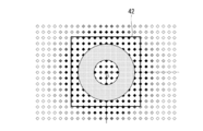
- FIGS. 21A and 21B are diagrams showing pointing vectors in the atmosphere when a conventional magnetic field resonance technique is used.
- FIGS. 21A and 21B energy flow perpendicular to the coil surface does not occur, and the energy flows in a spiral pattern.
- the power transmission efficiency is 90%.
- high power transmission efficiency cannot be obtained even if wireless power transmission is attempted in seawater using the power transmission device according to the conventional technology.
- 10% at a distance of 10 cm It has been found that only a power transmission efficiency of a certain degree can be obtained.
- FIGS. 18A and 18B show the state of the magnetic field under the phase condition in which the flux linkage passing through the helical coil 411 and the helical coil 421 of the power transmission unit 41 and the power reception unit 42 is maximum.
- the physical difference between the conventional magnetic field resonance technique and the power transmission device 4 according to the first example of the third embodiment will be described with reference to FIGS. 18A and 18B.
- the linkage magnetic flux passing through the helical coil 411 of the power transmission unit 41 and the linkage magnetic flux passing through the helical coil 421 of the power reception unit 42 are in opposite directions, thereby maximizing the magnetic field.
- a magnetic field parallel to the coil surface is generated.
- the resonance frequency is divided into two when tightly coupled, and the phase of the interlinkage magnetic flux passing through the coils of the power transmission unit and the power reception unit is higher at the higher resonance frequency. It is generally known to be in reverse phase. In the same technology, it is generally known that the phase of the interlinkage magnetic flux passing through the coils of the power transmission unit and the power reception unit is in phase in a loosely coupled state where the resonance frequency is not divided. According to the present invention, the phase of the interlinkage magnetic flux passing through the antenna coil of the power transmission unit and the power reception unit is reversed in a loose coupling state where the resonance frequency is not divided. This is an essential difference.
- FIG. 22 is a model diagram for simulation for demonstrating the effect of the power transmission device 5 according to the third embodiment.
- the power transmission device 5 includes a power transmission unit 51 and a power reception unit 52.
- the power transmission unit 51 and the power reception unit 52 are covered with seawater 53 as a good conductor medium.
- the power transmission unit 51 includes a spiral coil 5111, a loop coil 5112, an internal dielectric (first power transmission side inclusion) 512, an external dielectric (second power transmission side inclusion) 513, and a coated dielectric (third power transmission side inclusion). ) 514.
- the power reception unit 52 includes a spiral coil 5211, a loop coil 5212, an internal dielectric (first power reception side inclusion) 522, an external dielectric (second power reception side inclusion) 523, and a covering dielectric (third power reception side inclusion). 524.
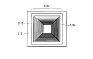
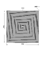
- FIGS. 23 and 24 are model views of the spiral coil 5111 (spiral coil 5211) in the second example of the third embodiment as viewed from the top and side surfaces, respectively.
- the spiral coil 5111 includes a dielectric substrate 5113 made of a fluororesin and a spiral wire 5114 made of a metal wire.
- the dielectric substrate 5113 has a thickness of 1 mm, a length of 270 mm, and a width of 270 mm.
- the spiral wiring 5114 has a length of 260 mm, a width of 260 mm, a wiring width of 6 mm, a thickness of 50 ⁇ m, and 10 turns.
- the loop coil 5112 includes a dielectric substrate 5115 made of fluororesin and a loop wiring 5116 made of metal wiring.
- the dielectric substrate 5115 has a thickness of 1 mm, a length of 270 mm, and a width of 270 mm.
- the loop wiring 5116 has a length of 260 mm, a width of 260 mm, a wiring width of 6 mm, and a thickness of 50 ⁇ m.
- Spiral coil 5111 and loop coil 5112 speak a distance of 3 mm in internal dielectric 512.
- the resonance frequency is about 1 MHz.
- the power reception unit 52 has the same configuration as the power transmission unit 51. However, the configuration shown here is an example, and the same effect can be obtained even if the power transmission unit 51 and the power reception unit 52 are not the same configuration.
- the resonant frequency of a power transmission part and a power receiving part can be made the same, and it becomes possible to obtain higher electric power transmission efficiency.
- FIG. 28 is a simulation model diagram for demonstrating the effect of the power transmission device 6 according to the third embodiment of the present invention.
- the power transmission device 6 includes a power transmission unit 61 and a power reception unit 62.
- the power transmission unit 61 and the power reception unit 62 are covered with seawater 63.
- the power transmission unit 61 includes a power transmission coil including a spiral coil 6111 and a spiral coil 6112, a first power transmission side inclusion unit 612 made of a first dielectric covering the power transmission coil, and a second dielectric covering the first power transmission side inclusion unit 612.
- the power reception unit 62 includes a power reception coil including a spiral coil 6211 and a spiral coil 6212, a first power reception side inclusion unit 622, a second power reception side inclusion unit 623, and a third power reception side inclusion unit 624. I have.
- the simulation model in the third example of the third embodiment includes a second power transmission side inclusion unit 613 (second power reception side inclusion unit 623) and a first power transmission side inclusion unit 612 ( Only the upper surface and the lower surface (surface parallel to the coil surface) of the first power receiving side inclusion portion 622) are covered.
- the first power transmission side inclusion unit 612 first power reception side inclusion unit 622 is sandwiched between the second power transmission side inclusion unit 613 (second power reception side inclusion unit 623).
- the side surface (surface perpendicular to the coil surface) of the first power transmission side inclusion unit 612 (first power reception side inclusion unit 622) is directly covered by the third power transmission side inclusion unit 614 (third power reception side inclusion unit 624). It has a structure that is called.
- FIG. 29 is a model diagram of the power transmission unit 61 in the third example of the third embodiment viewed from the side.
- the 1st power transmission side inclusion part 612 is comprised with the fluororesin of length 250mm, width 250mm, and height 4.5mm.
- the relative dielectric constant is 10.2 and the dielectric loss tangent is 0.0023.
- the 2nd power transmission side inclusion part 613 is comprised with two fluororesins of length 250mm, width 250mm, and height 6mm.
- the relative dielectric constant is 6.2 and the dielectric loss tangent is 0.0019.
- the 3rd power transmission side inclusion part 614 is comprised with acrylic 260 mm long, 260 mm wide, 26.5 mm high, and 5 mm thick.
- the relative permittivity of acrylic is 3.3, and the dielectric loss tangent is 0.04.
- the power reception unit 62 performs the simulation with the same configuration as the power transmission unit 61 described above.
- the spiral coil 6111 is composed of a wiring composed of 50 mm conductors with an outer periphery of 208 mm.
- the wiring has a diameter of 1 mm, and the wiring has an interval of 1 mm.
- the spiral coil 6112 has the same size as the spiral coil 6111.
- the spiral coil 6111 and the spiral coil 6112 are arranged at a distance of 0.5 mm.
- the outermost end of the spiral coil 6111 and the outermost end of the spiral coil 6112 serve as a high-frequency power feeding port.
- the direction of the spiral of the spiral coil 6111 and the direction of the spiral of the spiral coil 6112 are configured such that a magnetic field is generated in the same direction via the power supply port.
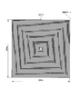
- FIGS. 32 and 33 are model diagrams of the spiral coils 6211 and 6212 of the power receiving unit 62 in the third example of the third embodiment as viewed from the power transmitting unit side.
- the spiral coil 6211 is composed of a wiring composed of a conductor with 50 turns and an outer periphery of 208 mm.
- the wiring has a diameter of 1 mm, and the wiring has an interval of 1 mm.
- the spiral coil 6212 has the same size as the spiral coil 6211.
- the spiral coil 6211 and the spiral coil 6212 are arranged with a distance of 0.5 mm.
- An outermost end portion of the spiral coil 6211 and an outermost end portion of the spiral coil 6212 serve as a power reception port for high-frequency power.
- the direction of the spiral of the spiral coil 6211 and the direction of the spiral of the spiral coil 6212 are configured such that a magnetic field is generated in the same direction via the power receiving port.
- the power transmission unit 61 and the power reception unit 62 were simulated at a distance of 10 cm in seawater, a high power transmission efficiency of 72% or more was obtained as shown in FIG.
- the resonance frequency is about 140 kHz.
- the power reception unit 62 has the same configuration as the power transmission unit 61.
- the configuration shown here is an example, and the same effect can be obtained even if the power transmission unit 61 and the power reception unit 62 are not the same configuration.
Landscapes
- Engineering & Computer Science (AREA)
- Power Engineering (AREA)
- Computer Networks & Wireless Communication (AREA)
- Signal Processing (AREA)
- Physics & Mathematics (AREA)
- Electromagnetism (AREA)
- Charge And Discharge Circuits For Batteries Or The Like (AREA)
- Near-Field Transmission Systems (AREA)
Abstract
Description
まず、大気中の電力伝送の場合、その媒質(大気)の伝搬中に消費するエネルギーはほとんどない。この場合の電力伝送効率の低下の要因は、主に、コイルでの導体損失、送電部と受電部の間の整合損、漏れ磁束などの反射損、そして放射損からなる。特に、特許文献2では、Q値の高いコイルを用い、送受電部近傍にエネルギーを溜める非放射現象とすることで、この放射損を効果的に抑制している。
以下、本発明の第一実施形態による電力伝送装置を、図面を参照して説明する。
図1は第一実施形態による電力伝送装置の構成を示す図である。
この図において、電力伝送装置1は、送電部11及び受電部12を備えている。また、送電部11及び受電部12は、良導体媒質13に覆われている。送電部11は、送電用コイル111及び送電用コイル111を覆う誘電体からなる送電側包含部112を備えている。また、受電部12は、送電部11と同じく、受電用コイル121及び受電側包含部122を備えている。送電用コイル111、受電用コイル121は、銅線などの導体を複数回巻いたものであり、一般的に、ヘリカルコイル、スパイラルコイル等が用いられるが、本実施形態においては、これらに限定されることはない。
なお、ここでは、電力伝送装置における送電部及び受電部を総称して電力伝送部とする。また、送電用コイル及び受電用コイルを総称して電力伝送用コイルとする。ここで、送電部は、受電部としての機能を備えていてもよいし、受電部は送電部としての機能を備えていてもよい。また、送電部と受電部が、同一の構成であってもよい。
図2は、無線電力が送電部11から受電部12へ伝搬する際の、当該無線電力にとっての等価回路図である。
送電部11及び受電部12は、さらに、送電用コイル111又は受電用コイル121のインピーダンスを調整する送電側インピーダンス調整部113、受電側インピーダンス調整部123を備えている。ここで、送電部11における送電用コイル111のインピーダンスは、主に、誘導成分(インダクタンス成分)L1及び容量成分(キャパシタンス成分)C1からなり、これらは、コイルの形状、巻き数、銅線の太さ、及び、送電側包含部112を構成する誘電体の誘電率やそのサイズ等によって一意に定まる。同様に、受電部12における受電用コイル121のインピーダンスも、誘導成分L2及び容量成分C2からなる。
なお、本稿においては、送電側インピーダンス調整部及び受電側インピーダンス調整部を総称して、単にインピーダンス調整部とする。
容量の可変部には、バラクタダイオード(可変容量ダイオード)を用いることができるし、複数の容量をスイッチトランジスタと組み合わせて構成することもできる。
図3に示すグラフによると、上記C1[pF]、C2[pF],C3[pF],d[cm]は以下の条件を満たす場合に、特に高い電力伝送効率が得られることがわかる。

なお、受電部12における受電用コイル121の径、及び、受電側包含部122の寸法比についても同様の効果を得ることができる。また、送電部11、受電部12ともに上記の条件を満たせば、より高い効果を得ることができる。
まず、送電部11において、交流電源(図示せず)が所定の周波数で交流電力を出力する。次に、出力された交流電力は送電用コイル111に供給され、送電用コイル111は、当該交流電力を、電磁エネルギーとして外部(良導体媒質13)へと送出する。次に、受電部12は、送出された電磁エネルギーを、受電用コイル121において送入する。ここで、送電側インピーダンス調整部113及び受電側インピーダンス調整部123は、送電部11、受電部12、良導体媒質13の各インピーダンスの合成インピーダンスが、伝送電力の周波数で共振するように調整されている。受電用コイル121によって送入された電力は、目的とする負荷(例えば、バッテリー等)に供給され、電力伝送が完了する。
ここで、電力伝送時において、送電部11と受電部12の間に生じる電界と磁界のシミュレーション結果を示す模式図を図5及び図6に示す。図5に示すとおり、本実施形態の電力伝送装置1では、コイル面に対して、その電界と磁界をほぼ平行にすることができる。その結果、図6に示すとおり、送電部11から受電部12へのポインティングベクトル(電磁エネルギーの流れ)をほぼ垂直に生じさせることが可能となる。
図7は本発明の第二実施形態による電力伝送装置の構成を示す図である。
次に、第二実施形態による電力伝送装置を、図面を参照しながら説明する。
この図において、電力伝送装置2は、送電部21及び受電部22を備えている。また、送電部21及び受電部22は、良導体媒質23に覆われている。送電部21は、送電用コイル211、送電用コイル211を覆う第一誘電体からなる第一送電側包含部212、及び、さらに第一送電側包含部212を覆う第二誘電体からなる第二送電側包含部213を備えている。また、受電部22は、送電部21と同じく、受電用コイル221及び第一受電側包含部222、第二受電側包含部223を備えている。
なお、本稿においては、第一送電側包含部及び第一受電側包含部を総称して第一包含部とし、第二送電側包含部及び第二受電側包含部を総称して第二包含部とする。
なお、本実施形態の電力伝送装置2においても、第一実施形態で説明したインピーダンス調整部を備えていてもよい。
図8が示すところによると、第二誘電体の誘電正接を第一誘電体の誘電正接よりも大きくすることで、より高い電力伝送効率が得られることがわかる。これは、第二送電側包含部213(第二受電側包含部223)を構成する第二誘電体によって、良導体媒質23への電界の拡がりを抑制する効果を得るとともに、第一送電側包含部212(第一受電側包含部222)を構成する第一誘電体の誘電正接を小さくすることで、送電用コイル211(受電用コイル221)近傍における誘電損失を低減させることができる効果に基づくものである。
図9が示すところによると、第二誘電体の比誘電率を第一誘電体の比誘電率よりも大きくすることで、より高い電力伝送効率が得られることがわかる。
まず、送電部21において、交流電源(図示せず)が所定の周波数で交流電力を出力する。次に、出力された交流電力は送電用コイル211に供給され、送電用コイル211は、当該交流電力を、電磁エネルギーとして外部(良導体媒質23)へと送出する。次に、受電部12は、送出された電磁エネルギーを、受電用コイル221において送入する。ここで、送電部21、受電部22、良導体媒質23の各インピーダンスの合成インピーダンスは、伝送電力の周波数で共振するように調整されている。受電用コイル221によって送入された電力は、目的とする負荷(例えば、バッテリー等)に供給され、電力伝送が完了する。
また、第二送電側包含部213及び第二受電側包含部223は、良導体媒質23中への電界の拡がりを抑え、これにより、良導体媒質13中に拡散して消滅する電磁エネルギーを最小限に抑える効果がある。
そして、第一送電側包含部212及び第一受電側包含部222は、送電用コイル211及び受電用コイル221近傍における誘電損失を低減させる効果がある。
図10は本発明の第三実施形態による電力伝送装置の構成を示す図である。
次に、第三実施形態による電力伝送装置を、図面を参照しながら説明する。
図10において、電力伝送装置3は、送電部31及び受電部32を備えている。また、送電部31及び受電部32は、良導体媒質33に覆われている。送電部31は、送電用コイル311、送電用コイル311を覆う第一誘電体からなる第一送電側包含部312、第一送電側包含部312を覆う第二誘電体からなる第二送電側包含部313、及び、第二送電側包含部313を覆う第三誘電体からなる第三送電側包含部314を備えている。また、受電部32は、送電部31と同じく、受電用コイル321及び第一受電側包含部322、第二受電側包含部323及び第三受電側包含部324を備えている。
なお、本稿においては、第三送電側包含部及び第三受電側包含部を総称して、被覆部とする。
また、第三誘電体からなる第三送電側包含部314、第三受電側包含部324は、液体である第二送電側包含部313、第二受電側包含部323を物理的に閉じ込める。
なお、第三実施の形態による電力伝送装置3においても、第一の実施形態で説明したインピーダンス調整部を備えていてもよい。
まず、送電部31において、交流電源(図示せず)が所定の周波数で交流電力を出力する。次に、出力された交流電力は送電用コイル311に供給され、送電用コイル311は、当該交流電力を、電磁エネルギーとして外部(良導体媒質33)へと送出する。次に、受電部32は、送出された電磁エネルギーを、受電用コイル321において送入する。ここで、送電部31、受電部32、良導体媒質33の各インピーダンスの合成インピーダンスは、伝送電力の周波数で共振するように調整されている。受電用コイル321によって送入された電力は、目的とする負荷(例えば、バッテリー等)に供給され、電力伝送が完了する。
また、第二送電側包含部313及び第二受電側包含部323は、良導体媒質33中への電界の拡がりを抑え、これにより、良導体媒質33中に拡散して消滅する電磁エネルギーを最小限に抑える効果がある。
そして、第一送電側包含部312及び第一受電側包含部322は、送電用コイル311及び受電用コイル321近傍における誘電損失を低減させる効果がある。
図11では、電力伝送装置1の送電部11が電力供給源14に具備され、受電部12が潜水艇15に具備されている。本発明を用いることで、潮流が起こって電力供給源14と潜水艇15の位置関係が変動した場合であっても、安定して電力供給を行うことが可能になる。
図12では、電力伝送装置1の送電部11が潜水艇16に具備され、受電部12が潜水艇17に具備されている。本発明を用いることで、潮流が起こって潜水艇16と潜水艇17の位置関係が変動した場合であっても、安定して電力供給を行うことが可能になる。
なお、受電部12を備える潜水艇17は、船舶または海底に敷設されたセンサー装置等であってもよい。
送電部11が電源ケーブル18の接続部に具備され、受電部12が電源ケーブル19の接続部に具備されている。本発明を用いることで、海水中であっても、無線で電力供給をすることで、ケーブル間を非接触で接続することが可能になり、電源ケーブルの交換が容易になり、磨耗することなく信頼性も向上する。
本発明の第三実施形態の第一実施例として、その効果を実証した具体的なシミュレーションモデルについて、図14を参照しながら説明する。
図14において、電力伝送装置4は、送電部41及び受電部42を備えている。また、送電部41及び受電部42は、良導体媒質として海水43に覆われている。前記送電部41は、ヘリカルコイル(送電用コイル)411、内部誘電体(第一送電側包含部)412、外部誘電体(第二送電側包含部)413、被覆誘電体(第三送電側包含部)414を備えている。前記受電部42は、ヘリカルコイル(受電用コイル)421、内部誘電体(第一受電側包含部)422、外部誘電体(第二受電側包含部)423、被覆誘電体(第三受電側包含部)424を備えている。
図15に示すヘリカルコイル411は、直径2mmの導線を、外径220mm、内径100mmで29巻きした単層コイルを2枚、距離3mm離して対向させた構造からなる。
この対抗させたヘリカルコイルに対して給電ポートから交流電力を印加する。内部誘電体412はフッ素樹脂で構成し、被覆誘電体414はアクリルで構成する。被覆誘電体414のサイズは、縦255mm、横255mm、高さ19mmである。前記電力伝送装置4の共振周波数は約1MHzである。ここで、本実施例では、ヘリカルコイルの外径のサイズd2と、被覆誘電体のサイズd1の比d1/d2が、1より大きい1.16であっても、充分高い電力伝送効率が得られている。ただし、d1/d2の比を、1.16より大きくすれば、さらに高い電力伝送効率が得られる。
受電部42は、送電部41と同じ構成としている。ただし、ここで示した構成は一例であって、送電部41と受電部42が同じ構成でなくても、同様の効果が得られる。
送電部41と受電部42との間の距離dを10cmとし、海水中において電力伝送効率のシミュレーションを行ったところ、図16に示すとおり、伝送電力の周波数fが1MHz付近において、40%以上の高い電力伝送効率を得ることができた。
上述した実施例による電力伝送装置4における電界、磁界、並びにポインティングベクトルに関して、詳細な三次元電磁界シミュレーションを行った結果について、図17A~図19Bを参照しながら説明する。
第三実施形態の第一の実施例では、図17Aおよび17Bに示すとおり、電界の流れがコイル面と平行な面に沿って回転しており、かつ、図18Aおよび18Bで示すとおり、磁界の流れがコイル面と平行な面に沿って放射状に生成されている。このような電界と磁界の流れに基づいて、コイル面とほぼ垂直な方向にポインティングベクトル(エネルギーの流れ)が発生する(図19Aおよび19B)。この結果、送電部41と受電部42との間の距離が10cm程度離れた海水中であっても、コイル面に対してほぼ垂直な方向にエネルギーの流れが形成され、海水中での長距離化が可能となる。
本実施例による電力伝送装置4の送電部41と受電部42を、大気中において、10cmの距離を離してシミュレーションを行った結果について、図20Aおよび20Bを参照しながら説明する。
図20Aおよび20Bに示すとおり、送受電部面に対して垂直なエネルギーの流れは生じず、エネルギーは螺旋を描くような流れとなっている。すなわち、コイル面に対してほぼ垂直なエネルギーの流れが生じる現象は、良導体媒質中を伝搬するエネルギー特有の現象であり、大気中を伝搬する際には生じない現象である。すなわち、本発明は、コイル面に対してほぼ垂直なエネルギーの流れが生じるという特有の現象を利用している。
次に、従来の磁界共鳴技術を用いた、大気中でのシミュレーションを行った結果について、図21Aおよび21Bを参照しながら説明する。
図21Aおよび21Bに示すとおり、この場合も、図20A、20Bと同様、コイル面に対して垂直なエネルギーの流れは生じずに、エネルギーは螺旋を描くような流れとなっている。この場合における電力伝送効率は90%である。なお、既に述べたように、この従来技術による電力伝送装置を用いて、海水中において、無線電力伝送を試みても高い電力伝送効率は得られず、シミュレーションの結果では、10cmの距離で10%程度の電力伝送効率しか得られないことが分かった。
従来の磁界共鳴技術と、第三実施形態の第一の実施例による電力伝送装置4との物理的な相違点について、図18Aおよび18Bを参照しながら説明する。
図18Aおよび18Bに示すとおり、送電部41のヘリカルコイル411を貫く鎖交磁束と、受電部42のヘリカルコイル421を貫く鎖交磁束が互いに逆方向の向きとなることで、磁界が最大となり、コイル面に対して平行な磁界を生成している。
一方、磁界共鳴を用いた無線電力伝送技術では、密結合にした場合に共振周波数が2つに分割し、高い方の共振周波数において、送電部と受電部のコイルを貫く鎖交磁束の位相が逆相となることが一般に知られている。また、同技術において、共振周波数が分割しない疎結合の状態においては、送電部と受電部のコイルを貫く鎖交磁束の位相が同相となることが一般に知られている。
本発明は、密結合状態ではなく、共振周波数が分割しない疎結合の状態で、送電部と受電部のアンテナ・コイルを貫く鎖交磁束の位相が逆相となることが、従来の磁界共鳴技術との本質的な違いである。
次に、本発明の第三実施形態の第二実施例として、その効果を実証した具体的なシミュレーション結果について、図22を参照しながら説明する。
図22において、電力伝送装置5は、送電部51及び受電部52を備えている。また、送電部51及び受電部52は、良導体媒質として海水53に覆われている。前記送電部51は、スパイラルコイル5111、ループコイル5112、内部誘電体(第一送電側包含部)512、外部誘電体(第二送電側包含部)513、被覆誘電体(第三送電側包含部)514を備えている。前記受電部52は、スパイラルコイル5211、ループコイル5212、内部誘電体(第一受電側包含部)522、外部誘電体(第二受電側包含部)523、被覆誘電体(第三受電側包含部)524を備えている。
スパイラルコイル5111は、フッ素樹脂からなる誘電体基板5113と金属配線からなるスパイラル配線5114で構成される。誘電体基板5113は厚さ1mm、縦270mm、横270mmで構成される。スパイラル配線5114は、縦260mm、横260mm、配線幅6mm、厚さ50μm、10巻きで構成される。
ループコイル5112は、フッ素樹脂からなる誘電体基板5115と金属配線からなるループ配線5116で構成される。誘電体基板5115は厚さ1mm、縦270mm、横270mmで構成される。ループ配線5116は、縦260mm、横260mm、配線幅6mm、厚さ50μmで構成される。
本実施例では、受電部52は、送電部51と同じ構成としている。ただし、ここで示した構成は一例であって、送電部51と受電部52が同じ構成でなくても、同様の効果が得られる。
次に、本発明の第三実施形態の第三実施例として、その効果を実証した具体的なシミュレーション結果について、図28を参照しながら説明する。
図28において、電力伝送装置6は、送電部61及び受電部62を備えている。また、送電部61及び受電部62は、海水63に覆われている。送電部61は、スパイラルコイル6111とスパイラルコイル6112からなる送電用コイル、送電用コイルを覆う第一誘電体からなる第一送電側包含部612、第一送電側包含部612を覆う第二誘電体からなる第二送電側包含部613、及び、第二送電側包含部613を覆う第三誘電体からなる第三送電側包含部614を備えている。また、受電部62は、送電部61と同じく、スパイラルコイル6211とスパイラルコイル6212からなる受電用コイル及び第一受電側包含部622、第二受電側包含部623及び第三受電側包含部624を備えている。
第一送電側包含部612は、縦250mm、横250mm、高さ4.5mmのフッ素樹脂で構成される。比誘電率は10.2、誘電正接は0.0023である。
また、第二送電側包含部613は、2つの、縦250mm、横250mm、高さ6mmのフッ素樹脂で構成される。比誘電率は6.2、誘電正接は0.0019である。
また、第三送電側包含部614は、縦260mm、横260mm、高さ26.5mm、厚さ5mmのアクリルで構成される。アクリルの比誘電率は3.3、誘電正接は0.04である。
なお、第三実施形態の第三の実施例においては、受電部62も、上述した送電部61と同じ構成としてシミュレーションを行っている。
スパイラルコイル6111は、外周辺208mm、50巻の導体からなる配線で構成される。前記配線の直径は1mm、前記配線の間隔は1mmである。スパイラルコイル6112は、スパイラルコイル6111と同サイズとした。スパイラルコイル6111とスパイラルコイル6112は、0.5mmの距離を離して配置される。スパイラルコイル6111の最外周の端部と、スパイラルコイル6112の最外周の端部が、高周波電力の給電ポートとなる。スパイラルコイル6111の螺旋の向きと、スパイラルコイル6112の螺旋の向きは、給電ポートを介して、同じ方向に磁界が発生する向きで構成する。
スパイラルコイル6211は、外周辺208mm、50巻の導体からなる配線で構成される。前記配線の直径は1mm、前記配線の間隔は1mmである。スパイラルコイル6212は、スパイラルコイル6211と同サイズとした。スパイラルコイル6211とスパイラルコイル6212は、0.5mmの距離を離して配置される。スパイラルコイル6211の最外周の端部と、スパイラルコイル6212の最外周の端部が、高周波電力の受電ポートとなる。スパイラルコイル6211の螺旋の向きと、スパイラルコイル6212の螺旋の向きは、受電ポートを介して、同じ方向に磁界が発生する向きで構成する。
第三実施形態の第三の実施例では、受電部62は、送電部61と同じ構成としている。ただし、ここで示した構成は一例であって、送電部61と受電部62が同じ構成でなくても、同様の効果が得られる。
11 送電部
111 送電用コイル
112 送電側包含部
113 送電側インピーダンス調整部
12 受電部
121 受電用コイル
122 受電側包含部
123 受電側インピーダンス調整部
13 良導体媒質
14 電力供給源
15 潜水艇
16 潜水艇
17 潜水艇
18 電源ケーブ
19 電源ケーブル
2 電力伝送装置
21 送電部
211 送電用コイル
212 第一送電側包含部
213 第二送電側包含部
22 受電部
221 受電用コイル
222 第一受電側包含部
223 第二受電側包含部
23 良導体媒質
3 電力伝送装置
31 送電部
311 送電用コイル
312 第一送電側包含部
313 第二送電側包含部
314 第三送電側包含部
32 受電部
321 受電用コイル
322 第一受電側包含部
323 第二受電側包含部
324 第三受電側包含部
33 良導体媒質
4 電力伝送装置
41 送電部
411 ヘリカルコイル
421 ヘリカルコイル
412 内部誘電体
422 内部誘電体
413 外部誘電体
423 外部誘電体
414 被膜誘電体
424 被膜誘電体
42 受電部
43 海水
5 電力伝送装置
51 送電部
5111 スパイラルコイル
5211 スパイラルコイル
5112 ループコイル
5212 ループコイル
5113 誘電体基板
5114 スパイラル配線
5115 誘電体基板
5116 ループ配線
512 内部誘電体
522 内部誘電体
513 外部誘電体
523 外部誘電体
514 被膜誘電体
524 被膜誘電体
52 受電部
53 海水
6 電力伝送装置
61 送電部
6111 スパイラルコイル
6112 スパイラルコイル
6211 スパイラルコイル
6212 スパイラルコイル
612 第一送電側包含部
613 第二送電側包含部
614 第三送電側包含部
62 受電部
622 第一受電側包含部
623 第二受電側包含部
624 第三受電側包含部
63 海水
Claims (17)
- 良導体媒質中において電力を無線で伝送する電力伝送装置であって、
無線で電力を送出する送電部と、
前記送電部から送出された無線電力を送入する受電部と、
を備え、
前記送電部及び受電部は、
電力伝送用コイルと、
前記電力伝送用コイルを覆う誘電体を有する包含部と、
を備え、
前記送電部のインピーダンスと、前記受電部のインピーダンスと、前記良導体媒質のインピーダンスで定まる周波数で共振させて電力伝送を行う電力伝送装置。 - 前記送電部のインピーダンスを構成するキャパシタンス成分(C1[pF])と、前記受電部のインピーダンスを構成するキャパシタンス成分(C2[pF])と、前記送電部、前記受電部、及び、その間に存在する前記良導体媒質で形成される容量のキャパシタンス成分(C3[pF])と、前記送電部と前記受電部との間隔距離(d[cm])が、30>C3・d/(C1+C2)>0.5の関係を満たす請求項1に記載の電力伝送装置。
- 前記送電部、前記受電部の少なくとも一方は、
自己のインピーダンスを可変にするインピーダンス調整部と、
を備えた請求項1または請求項2に記載の電力伝送装置。 - 前記包含部の電力伝送用コイル面に沿う方向の大きさ(d1[cm])と、前記電力伝送用コイルの外径(d2[cm])が、d1/d2>1.2の関係を満たす請求項1から請求項3の何れか一に記載の電力伝送装置。
- 前記包含部は、
前記電力伝送用コイルを覆う第一誘電体を有する第一包含部と、
前記第一包含部を覆う第二誘電体を有する第二包含部と、
を備えた請求項1から請求項4の何れか一項に記載の電力伝送装置。 - 前記包含部は、
さらに、前記第二包含部を覆う第三誘電体を有する被覆部と、
を備えた請求項5に記載の電力伝送装置。 - 前記第二誘電体は、前記良導体媒質と比重が等しい誘電体からなる請求項5または請求項6に記載の電力伝送装置。
- 前記第一誘電体の誘電正接が、前記第二誘電体の誘電正接よりも低いか、又は、同一である請求項5から請求項7の何れか一項に記載の電力伝送装置。
- 前記第一誘電体の比誘電率が、前記第二誘電体の比誘電率よりも低いか、又は、同一である請求項5から請求項8の何れか一項に記載の電力伝送装置。
- 前記良導体媒質は、
導電率が1×10⁻⁴より高く、かつ、比誘電率が1より高い請求項1から請求項9の何れか一項に記載の電力伝送装置。 - 前記良導体媒質が、海水、河川、淡水、水道水、土、コンクリートのいずれかである請求項1から請求項10の何れか一項に記載の電力伝送装置。
- 前記良導体媒質中に発生した電界の一部もしくは全部が、前記送電部または前記受電部の電力伝送用コイル面に対して略平行に回転しており、かつ、前記良導体媒質中に発生した磁界の一部もしくは全部が、前記送電部または前記受電部の電力伝送用コイル面に対して略平行に向いている請求項1から請求項11の何れか一項に記載の電力伝送装置。
- 前記送電部の電力伝送用コイルを貫く鎖交磁束と、前記受電部の電力伝送用コイルを貫く鎖交磁束が、磁界が最大となる位相条件で、互いに逆方向の向きとすることで、前記電力伝送用コイル面に対して平行な磁界を生成する請求項12に記載の電力伝送装置。
- 海水中に設置した電力供給源、船舶または潜水艇に前記送電部を搭載し、海水中に設置したセンサー、船舶または潜水艇に前記受電部を搭載し、前記送電部から前記受電部に無線で電力伝送を行う請求項1から請求項13の何れか一項に記載の電力伝送装置。
- 海水中に敷設された電源ケーブルの接続部に、前記送電部と前記受電部を用い、前記送電部から前記受電部に無線で電力伝送を行う請求項1から請求項14の何れか一項に記載の電力伝送装置。
- 前記送電部を情報伝送する送信機として用い、前記受電部を情報伝送する受信器として用いることで、電力伝送及び無線通信を同時に行う請求項1から請求項15の何れか一項に記載の電力伝送装置。
- 良導体媒質中において電力を無線で伝送する電力伝送方法であって、
包含部が、電力伝送用コイルを誘電体で覆い、
送電部が、無線で電力を送出し、
受電部が、送出された無線電力を送入し、
前記送電部のインピーダンスと、前記受電部のインピーダンスと、前記良導体媒質のインピーダンスで定まる周波数で共振させて電力伝送を行う電力伝送方法。
Priority Applications (6)
| Application Number | Priority Date | Filing Date | Title |
|---|---|---|---|
| RU2015109283/07A RU2594006C1 (ru) | 2012-08-31 | 2013-08-21 | Устройство передачи электрической энергии и способ передачи электрической энергии |
| IN2121DEN2015 IN2015DN02121A (ja) | 2012-08-31 | 2013-08-21 | |
| CN201380044578.0A CN104584380A (zh) | 2012-08-31 | 2013-08-21 | 电力传输设备和电力传输方法 |
| US14/423,999 US10020682B2 (en) | 2012-08-31 | 2013-08-21 | Electric power transmission device and electric power transmission method |
| JP2014532950A JP6467919B2 (ja) | 2012-08-31 | 2013-08-21 | 電力伝送装置及び電力伝送方法 |
| EP13834158.1A EP2892127B1 (en) | 2012-08-31 | 2013-08-21 | Electric power transmission device and electric power transmission method |
Applications Claiming Priority (2)
| Application Number | Priority Date | Filing Date | Title |
|---|---|---|---|
| JP2012191649 | 2012-08-31 | ||
| JP2012-191649 | 2012-08-31 |
Publications (1)
| Publication Number | Publication Date |
|---|---|
| WO2014034491A1 true WO2014034491A1 (ja) | 2014-03-06 |
Family
ID=50183306
Family Applications (1)
| Application Number | Title | Priority Date | Filing Date |
|---|---|---|---|
| PCT/JP2013/072289 WO2014034491A1 (ja) | 2012-08-31 | 2013-08-21 | 電力伝送装置及び電力伝送方法 |
Country Status (7)
| Country | Link |
|---|---|
| US (1) | US10020682B2 (ja) |
| EP (1) | EP2892127B1 (ja) |
| JP (1) | JP6467919B2 (ja) |
| CN (1) | CN104584380A (ja) |
| IN (1) | IN2015DN02121A (ja) |
| RU (1) | RU2594006C1 (ja) |
| WO (1) | WO2014034491A1 (ja) |
Cited By (8)
| Publication number | Priority date | Publication date | Assignee | Title |
|---|---|---|---|---|
| WO2014129531A1 (ja) * | 2013-02-20 | 2014-08-28 | 日本電気株式会社 | 電力伝送システム、送電装置、受電装置、及び電力伝送方法 |
| WO2015182069A1 (ja) * | 2014-05-27 | 2015-12-03 | 日本電気株式会社 | 電力伝送用アンテナおよび電力伝送システム |
| JP2016010168A (ja) * | 2014-06-20 | 2016-01-18 | 日本特殊陶業株式会社 | 共振器及び無線給電システム |
| JP2016127678A (ja) * | 2014-12-26 | 2016-07-11 | 日本電気株式会社 | 給電システム、移動体および給電装置 |
| WO2018003568A1 (ja) * | 2016-06-30 | 2018-01-04 | パナソニック株式会社 | 送電装置 |
| JP2018007354A (ja) * | 2016-06-29 | 2018-01-11 | 日立Geニュークリア・エナジー株式会社 | 無線給電装置及び無線給電方法 |
| JP2018046668A (ja) * | 2016-09-14 | 2018-03-22 | 日本電気株式会社 | 無線給電装置 |
| WO2018051936A1 (ja) * | 2016-09-15 | 2018-03-22 | 日本電気株式会社 | 無線給電装置及び無線給電方法 |
Families Citing this family (2)
| Publication number | Priority date | Publication date | Assignee | Title |
|---|---|---|---|---|
| CN105244157A (zh) * | 2015-10-17 | 2016-01-13 | 李德生 | 电能导磁环 |
| RU2740957C1 (ru) * | 2020-09-19 | 2021-01-22 | Общество с ограниченной ответственностью "Генезис-Таврида" | Способ обеспечения максимального коэффициента передачи электрической энергии высокой частоты при изменении расстояния между микрополосковыми структурами в некоторых пределах |
Citations (10)
| Publication number | Priority date | Publication date | Assignee | Title |
|---|---|---|---|---|
| JPH10108391A (ja) * | 1996-09-26 | 1998-04-24 | Nec Corp | 体内埋め込み装置用電力供給装置 |
| JP2004166384A (ja) * | 2002-11-12 | 2004-06-10 | Sharp Corp | 非接触型給電システムにおける電磁結合特性調整方法、給電装置、および非接触型給電システム |
| JP2007324532A (ja) * | 2006-06-05 | 2007-12-13 | Meleagros Corp | 電力伝送方法、電力伝送装置のコイルの選別方法および使用方法 |
| JP2011022640A (ja) | 2009-07-13 | 2011-02-03 | Sony Corp | 無線伝送システム、電子機器 |
| WO2011030804A1 (ja) * | 2009-09-08 | 2011-03-17 | 日本電気株式会社 | 無線電力変換器および無線通信装置 |
| JP4772744B2 (ja) | 2007-05-17 | 2011-09-14 | 昭和飛行機工業株式会社 | 非接触給電装置用の信号伝送コイル通信装置 |
| JP2011244530A (ja) * | 2010-05-14 | 2011-12-01 | Toyota Industries Corp | 共鳴型非接触給電システムの受電側設備 |
| JP2012504387A (ja) | 2008-09-27 | 2012-02-16 | ウィトリシティ コーポレーション | 無線エネルギー伝達システム |
| JP2012050321A (ja) * | 2010-07-28 | 2012-03-08 | Semiconductor Energy Lab Co Ltd | 無線給電システム、及び無線給電方法 |
| JP2012089618A (ja) * | 2010-10-18 | 2012-05-10 | Showa Aircraft Ind Co Ltd | 非接触給電装置の1次コイル配設構造 |
Family Cites Families (17)
| Publication number | Priority date | Publication date | Assignee | Title |
|---|---|---|---|---|
| EP0784384B1 (en) * | 1995-07-19 | 2003-04-16 | TDK Corporation | Antenna switch |
| DE19701357C2 (de) * | 1997-01-16 | 2003-02-27 | Schleifring Und Appbau Gmbh | Vorrichtung zur kontaktlosen Energieübertragung zwischen gegeneinander beweglichen Teilen |
| GB0210886D0 (en) | 2002-05-13 | 2002-06-19 | Zap Wireless Technologies Ltd | Improvements relating to contact-less power transfer |
| WO2008117635A1 (ja) | 2007-03-28 | 2008-10-02 | Radio Communication Systems Ltd. | 磁力波通信装置 |
| DE102007060811A1 (de) * | 2007-09-01 | 2009-03-05 | Maquet Gmbh & Co. Kg | Vorrichtung und Verfahren zur drahtlosen Energie- und/oder Datenübertragung zwischen einem Quellgerät und mindestens einem Zielgerät |
| JP5374850B2 (ja) | 2007-10-04 | 2013-12-25 | 沖電気工業株式会社 | 高効率非接触給電システム、高効率非接触給電方法、高効率非接触給電装置 |
| JP4394716B2 (ja) * | 2007-11-14 | 2010-01-06 | 株式会社日立製作所 | Nmr計測用プローブ |
| US20110043049A1 (en) * | 2008-09-27 | 2011-02-24 | Aristeidis Karalis | Wireless energy transfer with high-q resonators using field shaping to improve k |
| RU2408476C2 (ru) * | 2009-01-20 | 2011-01-10 | Государственное научное учреждение Всероссийский научно-исследовательский институт электрификации сельского хозяйства Российской академии сельскохозяйственных наук (ГНУ ВИЭСХ Россельхозакадемии) | Способ беспроводной передачи электрической энергии и устройство для его осуществления (варианты) |
| EP2396796A4 (en) * | 2009-02-13 | 2017-03-22 | Witricity Corporation | Wireless energy transfer in lossy environments |
| US8525370B2 (en) * | 2009-11-30 | 2013-09-03 | Broadcom Corporation | Wireless power circuit board and assembly |
| EP2415961A1 (en) | 2010-08-03 | 2012-02-08 | Vetco Gray Controls Limited | Supplying power to underwater devices |
| KR101441453B1 (ko) * | 2010-08-25 | 2014-09-18 | 한국전자통신연구원 | 무선 에너지 전송을 위한 자기 공진체에서 전기장 및 복사전력 감소 장치 및 그 방법 |
| JP5126324B2 (ja) * | 2010-09-10 | 2013-01-23 | トヨタ自動車株式会社 | 給電装置、および給電システムの制御方法 |
| US9077209B2 (en) * | 2011-01-20 | 2015-07-07 | Panasonic Intellectual Property Management Co., Ltd. | Power generation system, power generating module, module fixing device and method for installing power generation system |
| CA2827456C (en) | 2011-02-21 | 2020-12-01 | Wisub As | Underwater connector arrangement |
| WO2012157012A1 (en) * | 2011-05-13 | 2012-11-22 | Murata Manufacturing Co., Ltd. | Power transmitting device, power receiving device, and power transmission system |
-
2013
- 2013-08-21 WO PCT/JP2013/072289 patent/WO2014034491A1/ja active Application Filing
- 2013-08-21 RU RU2015109283/07A patent/RU2594006C1/ru not_active IP Right Cessation
- 2013-08-21 CN CN201380044578.0A patent/CN104584380A/zh active Pending
- 2013-08-21 JP JP2014532950A patent/JP6467919B2/ja active Active
- 2013-08-21 US US14/423,999 patent/US10020682B2/en active Active
- 2013-08-21 EP EP13834158.1A patent/EP2892127B1/en active Active
- 2013-08-21 IN IN2121DEN2015 patent/IN2015DN02121A/en unknown
Patent Citations (10)
| Publication number | Priority date | Publication date | Assignee | Title |
|---|---|---|---|---|
| JPH10108391A (ja) * | 1996-09-26 | 1998-04-24 | Nec Corp | 体内埋め込み装置用電力供給装置 |
| JP2004166384A (ja) * | 2002-11-12 | 2004-06-10 | Sharp Corp | 非接触型給電システムにおける電磁結合特性調整方法、給電装置、および非接触型給電システム |
| JP2007324532A (ja) * | 2006-06-05 | 2007-12-13 | Meleagros Corp | 電力伝送方法、電力伝送装置のコイルの選別方法および使用方法 |
| JP4772744B2 (ja) | 2007-05-17 | 2011-09-14 | 昭和飛行機工業株式会社 | 非接触給電装置用の信号伝送コイル通信装置 |
| JP2012504387A (ja) | 2008-09-27 | 2012-02-16 | ウィトリシティ コーポレーション | 無線エネルギー伝達システム |
| JP2011022640A (ja) | 2009-07-13 | 2011-02-03 | Sony Corp | 無線伝送システム、電子機器 |
| WO2011030804A1 (ja) * | 2009-09-08 | 2011-03-17 | 日本電気株式会社 | 無線電力変換器および無線通信装置 |
| JP2011244530A (ja) * | 2010-05-14 | 2011-12-01 | Toyota Industries Corp | 共鳴型非接触給電システムの受電側設備 |
| JP2012050321A (ja) * | 2010-07-28 | 2012-03-08 | Semiconductor Energy Lab Co Ltd | 無線給電システム、及び無線給電方法 |
| JP2012089618A (ja) * | 2010-10-18 | 2012-05-10 | Showa Aircraft Ind Co Ltd | 非接触給電装置の1次コイル配設構造 |
Cited By (17)
| Publication number | Priority date | Publication date | Assignee | Title |
|---|---|---|---|---|
| US9887681B2 (en) | 2013-02-20 | 2018-02-06 | Nec Corporation | Power transmission system, transmission apparatus, receiving apparatus, and power transmission method |
| WO2014129531A1 (ja) * | 2013-02-20 | 2014-08-28 | 日本電気株式会社 | 電力伝送システム、送電装置、受電装置、及び電力伝送方法 |
| WO2015182069A1 (ja) * | 2014-05-27 | 2015-12-03 | 日本電気株式会社 | 電力伝送用アンテナおよび電力伝送システム |
| JP2016010168A (ja) * | 2014-06-20 | 2016-01-18 | 日本特殊陶業株式会社 | 共振器及び無線給電システム |
| JP2016127678A (ja) * | 2014-12-26 | 2016-07-11 | 日本電気株式会社 | 給電システム、移動体および給電装置 |
| JP2018007354A (ja) * | 2016-06-29 | 2018-01-11 | 日立Geニュークリア・エナジー株式会社 | 無線給電装置及び無線給電方法 |
| US10790705B2 (en) | 2016-06-30 | 2020-09-29 | Panasonic Corporation | Power transmission device |
| JP2018007400A (ja) * | 2016-06-30 | 2018-01-11 | パナソニック株式会社 | 送電装置 |
| WO2018003568A1 (ja) * | 2016-06-30 | 2018-01-04 | パナソニック株式会社 | 送電装置 |
| JP2020178531A (ja) * | 2016-06-30 | 2020-10-29 | パナソニック株式会社 | 送電装置 |
| JP2018046668A (ja) * | 2016-09-14 | 2018-03-22 | 日本電気株式会社 | 無線給電装置 |
| US10944292B2 (en) | 2016-09-14 | 2021-03-09 | Nec Corporation | Wireless power supply device |
| WO2018051936A1 (ja) * | 2016-09-15 | 2018-03-22 | 日本電気株式会社 | 無線給電装置及び無線給電方法 |
| GB2568200A (en) * | 2016-09-15 | 2019-05-08 | Nec Corp | Wireless power supply device and wireless power supply method |
| JPWO2018051936A1 (ja) * | 2016-09-15 | 2019-06-24 | 日本電気株式会社 | 無線給電装置及び無線給電方法 |
| US10951066B2 (en) | 2016-09-15 | 2021-03-16 | Nec Corporation | Wireless power supply device and wireless power supply method |
| GB2568200B (en) * | 2016-09-15 | 2021-12-08 | Nec Corp | Wireless power supply device and wireless power supply method |
Also Published As
| Publication number | Publication date |
|---|---|
| RU2594006C1 (ru) | 2016-08-10 |
| JP6467919B2 (ja) | 2019-02-13 |
| EP2892127B1 (en) | 2020-06-24 |
| EP2892127A4 (en) | 2016-08-17 |
| EP2892127A1 (en) | 2015-07-08 |
| JPWO2014034491A1 (ja) | 2016-08-08 |
| CN104584380A (zh) | 2015-04-29 |
| US20150303702A1 (en) | 2015-10-22 |
| US10020682B2 (en) | 2018-07-10 |
| IN2015DN02121A (ja) | 2015-08-14 |
Similar Documents
| Publication | Publication Date | Title |
|---|---|---|
| JP6467919B2 (ja) | 電力伝送装置及び電力伝送方法 | |
| JP6237640B2 (ja) | 電力伝送装置及び電力伝送方法 | |
| JP6172259B2 (ja) | 電力伝送システム、送電装置、受電装置、及び電力伝送方法 | |
| US10038342B2 (en) | Power transfer system with shielding body, power transmitting device with shielding body, and power transfer method for power transmitting system | |
| US11282639B2 (en) | Antenna device and electronic apparatus | |
| JP2011086890A (ja) | ワイヤレス給電装置、ワイヤレス受電装置およびワイヤレス電力伝送システム | |
| KR20110004322A (ko) | 무선 전력 전송 시스템 및 상기 시스템을 위한 공진기 | |
| JP2011045045A (ja) | 送受電用アンテナ及び送電器 | |
| WO2015087724A1 (ja) | 磁力波アンテナおよびそれを用いる磁力波通信装置 | |
| JP2012222961A (ja) | アンテナモジュールおよび非接触電力伝送システム | |
| JP6098284B2 (ja) | 電力伝送システム、送電装置、受電装置、及び電力伝送方法 | |
| JP2015142224A (ja) | アンテナ装置および電子機器 | |
| JP6717381B2 (ja) | 無線給電装置及び無線給電方法 | |
| US10944292B2 (en) | Wireless power supply device | |
| JP2016059146A (ja) | 海水中給電システム | |
| JP7333938B2 (ja) | 水中無線電力伝送システム | |
| JP2017005952A (ja) | 非接触電力送電装置、非接触電力受電装置、及び、非接触電力伝送システム | |
| WO2013128518A1 (ja) | 送電装置、受電装置、電力供給システム及び電子機器 |
Legal Events
| Date | Code | Title | Description |
|---|---|---|---|
| 121 | Ep: the epo has been informed by wipo that ep was designated in this application |
Ref document number: 13834158 Country of ref document: EP Kind code of ref document: A1 |
|
| ENP | Entry into the national phase |
Ref document number: 2014532950 Country of ref document: JP Kind code of ref document: A |
|
| WWE | Wipo information: entry into national phase |
Ref document number: 14423999 Country of ref document: US |
|
| NENP | Non-entry into the national phase |
Ref country code: DE |
|
| ENP | Entry into the national phase |
Ref document number: 2015109283 Country of ref document: RU Kind code of ref document: A |