WO2014034309A1 - 車体後部構造 - Google Patents
車体後部構造 Download PDFInfo
- Publication number
- WO2014034309A1 WO2014034309A1 PCT/JP2013/069381 JP2013069381W WO2014034309A1 WO 2014034309 A1 WO2014034309 A1 WO 2014034309A1 JP 2013069381 W JP2013069381 W JP 2013069381W WO 2014034309 A1 WO2014034309 A1 WO 2014034309A1
- Authority
- WO
- WIPO (PCT)
- Prior art keywords
- parcel
- section
- vehicle body
- support
- closed cross
- Prior art date
- Legal status (The legal status is an assumption and is not a legal conclusion. Google has not performed a legal analysis and makes no representation as to the accuracy of the status listed.)
- Ceased
Links
Images








Classifications
-
- B—PERFORMING OPERATIONS; TRANSPORTING
- B62—LAND VEHICLES FOR TRAVELLING OTHERWISE THAN ON RAILS
- B62D—MOTOR VEHICLES; TRAILERS
- B62D21/00—Understructures, i.e. chassis frame on which a vehicle body may be mounted
- B62D21/15—Understructures, i.e. chassis frame on which a vehicle body may be mounted having impact absorbing means, e.g. a frame designed to permanently or temporarily change shape or dimension upon impact with another body
- B62D21/157—Understructures, i.e. chassis frame on which a vehicle body may be mounted having impact absorbing means, e.g. a frame designed to permanently or temporarily change shape or dimension upon impact with another body for side impacts
-
- B—PERFORMING OPERATIONS; TRANSPORTING
- B62—LAND VEHICLES FOR TRAVELLING OTHERWISE THAN ON RAILS
- B62D—MOTOR VEHICLES; TRAILERS
- B62D25/00—Superstructure or monocoque structure sub-units; Parts or details thereof not otherwise provided for
- B62D25/08—Front or rear portions
- B62D25/087—Luggage compartments
-
- B—PERFORMING OPERATIONS; TRANSPORTING
- B62—LAND VEHICLES FOR TRAVELLING OTHERWISE THAN ON RAILS
- B62D—MOTOR VEHICLES; TRAILERS
- B62D25/00—Superstructure or monocoque structure sub-units; Parts or details thereof not otherwise provided for
- B62D25/08—Front or rear portions
- B62D25/088—Details of structures as upper supports for springs or dampers
-
- B—PERFORMING OPERATIONS; TRANSPORTING
- B62—LAND VEHICLES FOR TRAVELLING OTHERWISE THAN ON RAILS
- B62D—MOTOR VEHICLES; TRAILERS
- B62D27/00—Connections between superstructure or understructure sub-units
- B62D27/02—Connections between superstructure or understructure sub-units rigid
Definitions
- the present invention relates to a rear structure of a vehicle body in which left and right vehicle body side portions are constituted by a rear wheel house and a rear pillar, rear parcels are provided between the left and right vehicle body side portions, and a luggage compartment and a vehicle compartment are partitioned by the rear parcels.
- a rear parcel is provided between left and right vehicle body side parts, a luggage compartment and a vehicle compartment are partitioned by the rear parcel, and a closed cross section is provided at the front end of the rear parcel (for example, known) , See Patent Document 1).
- the closed cross-sectional portion is provided over the left and right wheel houses, and the left and right end portions are disposed on the upper portions of the left and right wheel houses.
- each opening is arrange
- a first reinforcement is provided in the wheel house, a second reinforcement is provided in the first reinforcement, a damper base (damper bracket) is supported by the second reinforcement, and a damper (shock absorber) is provided in the damper base.
- a damper base damper bracket
- a damper shock absorber
- a connecting gusset is extended from the upper part of the rear wheel house toward the rear of the vehicle body along the rear wall part, and a rear pillar reinforcement is formed upward from the upper part of the rear wheel house along the side wall part.
- a structure in which a ment is extended to a rear pillar see, for example, Patent Document 3. According to the rear structure of the vehicle body, it is possible to ensure the rigidity and strength of the rear wheel house by reinforcing the rear wheel house with a connecting gusset or a rear pillar reinforcement.
- the rear parcel is usually provided in the rear structure of the vehicle body as a member that separates the cargo compartment from the passenger compartment.
- JP-A-9-240510 Japanese Patent Laid-Open No. 11-348826 JP 2006-69268 A
- a pair of vehicle body side portions that are constituted by a rear wheel house and a rear pillar and are provided at a predetermined interval in the vehicle width direction, and a load provided between the pair of vehicle body side portions.
- a rear parcel that partitions the compartment and the vehicle compartment; a parcel cross member that is joined to the lower side of the rear parcel and that extends in the vehicle width direction together with the rear parcel; and joined to the first closed cross section;
- a vehicle body rear structure including a rear parcel member and a parcel support that constitute a main part of a second closed cross-section portion that continues from one closed cross-section portion to the vehicle body side portion.
- the rear wheel house includes a damper base at an upper portion, and the damper base constitutes a part of the second closed cross section.
- the rear parcel has an upper surface that partitions the cargo compartment and the vehicle compartment in a vertical direction, and a front surface that hangs downward from the upper surface
- the parcel cross member includes: A lower surface opposed to the upper surface, and a rear surface opposed to the front surface
- the first closed cross-sectional portion includes the upper surface and the front surface of the rear parcel, the lower surface and the rear surface of the parcel cross member
- the second closed cross-section portion is configured such that the rear parcel member that continues outside the vehicle width of the rear surface, the parcel support that continues to the upper surface and the front surface, and the damper base that continues to the lower surface, Consists of.
- the parcel support includes a first surface continuous with the upper surface, and a lower end that is suspended downward from a front end of the first surface and a lower end joined in the middle of the rear parcel member in the vertical direction.
- a first support member comprising: a second surface; a third surface extending forward from a lower end of the second surface; and a first surface suspended downward from a front end of the third surface and joined to the damper base.
- a second support member comprising four surfaces, wherein the second closed cross-section portion includes an upper closed cross-section portion constituted by the rear parcel member and the first support member, the rear parcel member, And a lower closed cross-section portion constituted by the support member and the damper base.
- the rear parcel has a first ridge line between the upper surface and the front surface, and the second support member is between the third surface and the fourth surface. And a second ridge line extending outward in the vehicle width direction continuously to the first ridge line.
- the second support member includes a work hole on the third surface for allowing the damper base to be seen.
- a bulkhead for partitioning the first closed cross section and the second closed cross section is provided.
- the vehicle body rear structure further connects the end portion on the inner side in the vehicle width direction of the damper base and the end portion on the outer side in the vehicle width direction on the lower surface of the parcel cross member.
- a parcel shelf support that forms part of the second closed cross section.
- the rear wheel house includes a damper base at an upper portion thereof, and the rear parcel includes an upper surface that divides the cargo compartment and the vehicle compartment in a vertical direction, and downward from a front end of the upper surface.
- the parcel cross member has a lower surface facing the upper surface and a rear surface facing the front surface, and an end portion on the vehicle width direction outside of the rear surface and the rear pillar.
- a rear parcel member to be connected, a parcel shelf support for connecting the lower end of the lower surface in the vehicle width direction and the damper base, and an upper portion of the damper base are provided on the rear parcel member and the parcel shelf support.
- the vehicle body rear structure further includes a first support member that is joined to the rear parcel member and forms an upper closed section together with the rear parcel member. Are connected so as to be continuous with the first closed cross section, and the three members are joined in a state where the damper support is superimposed on the rear parcel member and the first support member.
- the rear structure of the vehicle body further includes a second support member joined to the rear parcel member and the damper base and constituting a lower closed cross section with the first closed cross section.
- the lower closed cross-section portion is connected to the first closed cross-section portion so that the three members are joined in a state where the damper support is superimposed on the rear parcel member and the second support member.
- the vehicle body rear structure is further joined to the rear parcel member, and forms a top closed cross section with the rear parcel member, the rear parcel member,
- a second support member which is joined to the damper base and forms a lower closed cross-section portion together with the first closed cross-section portion, and the upper closed cross-section portion and the lower closed cross-section portion respectively correspond to the first closed cross-section portion.
- Protruding flanges that are connected in series and are alternately arranged in the vehicle width direction are provided on each of the first support member and the second support member, and the protruding flanges of the rear parcel member and the first support member are provided.
- Three members are joined to each other with the damper support being superposed on the rear parcel member and the second support.
- Third member are joined in a superposed state of the damper support to the protruding flange of the member.
- the rear wheel house includes a damper base at an upper portion, connects the parcel cross member and the rear pillar, and a lower parcel member whose lower end is joined to the damper base; A rear wheel house patch which is joined along the rear wheel house and whose upper end is joined to the rear parcel member.
- the damper base includes a damper support surface portion, and a base flange that extends downward from a periphery of the damper support surface portion and to which the rear wheel house is joined, and the rear parcel.
- the member includes a first joint portion joined to the base flange, and a first extension portion extending downward from the first joint portion, and the first extension portion includes the rear wheel house. The three members are joined while being superposed on the patch and the rear wheel house.
- the first joint portion and the exposure hole for exposing the damper base or the rear wheel house are alternately arranged in the vehicle width direction
- the rear wheel house patch includes a second joint portion joined to the rear wheel house, and a second extension portion extending upward from the second joint portion and exposed from the exposure hole, Three members are joined in a state in which the second extending portion is overlapped with the base flange and the rear wheel house.
- the rear wheel house includes a side wall facing the center in the vehicle width direction, a front wall extending from the front end of the side wall to the vehicle width outside, and a rear end of the side wall.
- a rear wall extending outward in the vehicle width, and a U-shaped cross section formed by the rear wheel house patch provided along a ridge line between the side wall and the rear wall, It has an extended reinforcing portion extending from the middle in the longitudinal direction toward the vehicle width outside.
- the first closed cross-section portion is configured (formed) by the rear parcel and the parcel cross member
- the main portion of the second closed cross-section portion is configured by the rear parcel member and the parcel support.
- the second closed cross section was continued from the first closed cross section to the vehicle body side.
- a part of the second closed cross section is configured by the damper base provided at the upper part of the rear wheel house.
- the damper base is made continuous with the lower surface of the parcel cross member. Therefore, when transmitting the load of the first closed cross-section portion (parcel cross member) to the second closed cross-section portion (damper base), the transmitted load is passed through the damper base to the rear wheel house having relatively high rigidity and strength. I can tell you. As a result, the transmitted load can be suitably supported by the rear wheel house, so that the rigidity and strength of the rear portion of the vehicle body can be further improved.
- the second closed cross-section portion is constituted by the upper closed cross-section portion and the lower closed cross-section portion, and the upper surface of the lower closed cross-section portion is formed by the third surface of the second support member.
- the third surface of the second support member extends forward from the lower end of the second surface.
- an upper closed cross-section portion and a lower closed cross-section portion constituting the second closed cross-section portion are provided continuously between the first closed cross-section portion and the vehicle body side portion.
- the rear parcel has a first ridge line
- the second support member has a second ridge line.
- strength between a 1st closed cross-section part and a 2nd closed cross-section part can further be improved by providing the bulkhead which partitions off a 1st closed cross-section part and a 2nd closed cross-section part. .
- the load can be more suitably (efficiently) transmitted between the vehicle body side portion and the rear parcel, so that the rigidity and strength of the vehicle body rear portion can be further improved.
- the end portion on the inner side in the vehicle width direction of the damper base and the end portion on the outer side in the vehicle width direction of the parcel cross member (lower surface) are connected by the parcel shelf support.
- This parcel shelf support constitutes a part of the second closed cross section. Therefore, even if the rear parcel is provided above the damper base, the second closed cross section can be connected to the first closed cross section. As a result, the load can be transmitted suitably (efficiently) between the vehicle body side portion and the rear parcel, so that the rigidity and strength of the vehicle body rear portion can be improved.
- the rear parcel member is connected to the rear surface and the rear pillar of the parcel cross member
- the parcel shelf support is connected to the lower surface of the parcel cross member and the damper base.
- the damper support can be firmly supported by joining the damper support to the rear parcel member and the parcel shelf support.
- the load is transmitted from the upper part of the damper to the damper base and the damper support. Since the rigidity and strength of the damper base are sufficiently increased, the transmitted load can be efficiently transmitted to the rear pillar and the rear parcel via the rear parcel member and the parcel shelf support. Thereby, the load transmitted from the upper part of the damper to the damper support and the damper base can be suitably supported by the rear pillar and the rear parcel.
- the three members are joined together with the damper support superimposed on the rear parcel member and the first support member. Accordingly, since a large plate thickness dimension can be secured at the joint portion of the three members, the three members of the rear parcel member, the first support member, and the damper support can be firmly joined. Thereby, the rigidity and strength of the rear part of the vehicle body can be improved by increasing the joint strength of the joint part of the three members.
- the three members are joined in a state where the damper support is superimposed on the rear parcel member and the second support member. Accordingly, since a large plate thickness dimension can be secured at the joint portion of the three members, the three members of the rear parcel member, the second support member, and the damper support can be firmly joined. Thereby, the rigidity and strength of the rear part of the vehicle body can be improved by increasing the joint strength of the joint part of the three members.
- the first support member and the second support member are provided with protruding flanges, and the protruding flanges of the support members are alternately arranged in the vehicle width direction. Therefore, by joining the three members in a state where the protruding flange of the first support member is superimposed on the rear parcel member and the damper support, a large plate thickness dimension can be secured at the joint portion of the three members. Thereby, since the three members of the rear parcel member, the damper support, and the protruding flange of the first support member can be firmly joined, the joining strength of the joint portion of the three members can be increased.
- the plate thickness dimension becomes too large at the joint portion of the four members, and each member It is difficult to securely bond. Therefore, in the invention according to claim 12, the projecting flanges of the first support member and the second support member are alternately arranged in the vehicle width direction. As a result, the first support member and the second support member can be reliably joined to the rear parcel member and the damper support, respectively, so that the rigidity and strength of the rear portion of the vehicle body can be improved.
- the load can be efficiently transmitted between the parcel cross member (that is, the rear parcel) and the rear pillar. Further, the rear wheel house patch was joined along the rear wheel house, and the upper end of the rear wheel house patch was joined to the rear parcel member. Therefore, a load can be efficiently transmitted between the rear wheel house and the rear parcel member.
- the rigidity and strength of the rear part of the vehicle body can be improved by connecting the parcel cross member and the rear pillar with the rear parcel member and joining the upper end of the rear wheel house patch to the rear parcel member.
- a load can be efficiently transmitted between the rear wheel house, the rear parcel, and the rear pillar.
- the three members are joined by superimposing the first extension portion of the rear parcel member on the rear wheel house patch and the rear wheel house. Therefore, since a large plate thickness dimension can be secured at the joint portion of the three members, the three members of the first extension portion, the rear wheel house patch, and the rear wheel house can be firmly joined. Thereby, the rigidity and strength of the rear part of the vehicle body can be improved by increasing the joint strength of the joint part of the three members.
- the three members are joined by superimposing the second extending portion of the rear wheel house patch on the base flange and the rear wheel house. Therefore, since a large plate thickness dimension can be secured in the joint portion of the three members, the three members of the second extension portion, the base flange, and the rear wheel house can be firmly joined. Thereby, the rigidity and strength of the rear part of the vehicle body can be improved by increasing the joint strength of the joint part of the three members.
- the rear wheel house patch is provided along the ridge line of the rear wheel house.
- the ridge line is a relatively rigid part of the rear wheel house.
- the rear wheel house patch can be suitably (effectively) reinforced by providing the rear wheel house patch along the ridgeline.
- the extending reinforcing part is extended from the middle in the longitudinal direction of the rear wheel house patch toward the vehicle width outer side (vehicle body side).
- the strength difference between the ridgeline of the rear wheel house and the other part can be suppressed to a small value.
- stress concentration due to the load input to the rear wheel house is suppressed, and furthermore, the input load can be distributed to the side of the vehicle body through the extended reinforcement portion, so that the rigidity and strength of the rear wheel house (that is, the rear of the vehicle body) can be reduced. Can be improved.
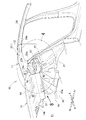
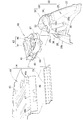
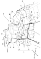
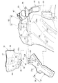
- FIG. 2 is an exploded perspective view showing a state in which a left support unit and a rear parcel unit are disassembled from the vehicle body rear part structure of FIG. 1.
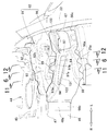
- FIG. 2 is an exploded perspective view showing a state in which a rear parcel unit is disassembled from the vehicle body rear structure of FIG. 1.
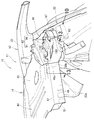
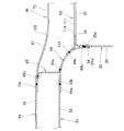
- FIG. 4 is an enlarged view of part 4 of FIG. 1.
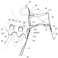
- FIG. 6 is a sectional view taken along line 6-6 of FIG. It is a principal part enlarged view of FIG. FIG.
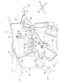
- FIG. 8 is a view taken in the direction of arrow 8 in FIG. 1.
- FIG. 2 is a perspective view showing a joined state of a parcel member and a parcel cross member of the vehicle body rear structure of FIG. 1.
- FIG. 10 is a view taken in the direction of arrow 10 in FIG. 4.
- FIG. 11 is a sectional view taken along line 11-11 in FIG. 12 is a sectional view taken along line 12-12 of FIG.
- FIG. 13 is a sectional view taken along line 13-13 of FIG.
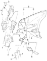
- FIG. 10 is an enlarged view of a portion 14 in FIG. 8. It is a disassembled perspective view which shows the vehicle body rear part structure of FIG.
- FIG. 16 is a sectional view taken along line 16-16 of FIG.
- FIG. 17 is a sectional view taken along line 17-17 in FIG.
- the vehicle body rear structure 10 includes left and right vehicle body side portions (a pair of vehicle body side portions and a right vehicle body side portion not shown) provided at predetermined intervals in the vehicle width direction of the vehicle body rear portion 11. 12, a rear parcel unit 14 provided between the left and right vehicle body side parts 12, a left support unit 16 that supports the left end 14 a of the rear parcel unit 14, and a right support unit (not shown) that supports the right end 14 b of the rear parcel unit 14. )).
- the left and right vehicle body side portions 12 are symmetrical members, and the left vehicle body side portion 12 will be described in detail below and the description of the right vehicle body side portion will be omitted.
- the left and right support units 16 are symmetrical members. The left support unit 16 will be described in detail below, and the description of the right support unit will be omitted.
- the left vehicle body side portion 12 includes a left rear wheel house (rear wheel house) 22 provided on the left rear side frame 21 and a left rear pillar (rear pillar) 23 provided on an upper portion 22 a of the left rear wheel house 22. .
- the left rear wheel house 22 includes a wheel house body 25 that can store a left rear wheel and a left damper (shock absorber), and a damper base 31 provided on the wheel house body 25. ing.
- the wheel house body 25 includes a wheel side wall (side wall) 26 facing the center side in the vehicle width direction, a wheel front wall (front wall) 27 extending outward from the front end 26 a of the wheel side wall 26, and the wheel side wall 26. It has a wheel rear wall (rear wall) 28 (see also FIG. 8) that extends outward from the rear end 26b toward the vehicle width.
- the wheel house body 25 includes a U-shaped cross section formed in a substantially U shape in the horizontal cross section by the wheel side wall 26, the wheel front wall 27, and the wheel rear wall 28. By including the U-shaped cross section in the wheel house body 25, the wheel house body 25 (that is, the left rear wheel house 22) can be formed as a member having relatively high rigidity and strength.
- the damper base 31 has a damper support surface part (upper part) 32 that covers the upper opening of the left rear wheel house 22, and a base flange 34 that extends downward (extends) from the peripheral edge 32 a of the damper support surface part 32.
- the damper support surface portion 32 is formed with a damper mounting hole 33 for mounting an upper portion of a damper (shock absorber) (not shown).
- the base flange 34 is joined to the inner peripheral wall 25b (see FIG. 6) of the wheel house body 25 (upper part 25a). By joining the base flange 34 to the inner peripheral wall 25b of the upper portion 25a, the upper opening 25c of the wheel house body 25 is closed by the damper support surface portion 32.
- a damper (not shown) is attached to the damper support surface portion 32 of the damper base 31. This damper is housed in the internal space of the left rear wheel house 22.
- a wheel house patch (rear wheel house patch) 36 (see also FIG. 5) is joined along the rear part (wheel side wall 26 and wheel rear wall 28) of the wheel house body 25. The wheel house patch 36 will be described in detail later.
- the left rear pillar 23 is provided so as to extend from the rear end 24a of the left roof side rail 24 to the rear of the vehicle body and downward. Further, the lower end 23 a of the left rear pillar 23 is joined to the floor 18 and the rear panel 19. A substantially central portion 23 b of the left rear pillar 23 is provided on the upper portion 22 a of the left rear wheel house 22.
- the rear parcel unit 14 is provided between the left and right vehicle body side portions 12 and above the left and right rear wheel houses 22. Therefore, the left and right end portions of the rear parcel unit 14 are provided in the left and right rear wheel houses 22 via the left and right support units 16, respectively.
- the rear parcel unit 14 includes a rear parcel 44 that partitions the cargo compartment 41 and the vehicle compartment 42, and a parcel cross member 51 that is joined to the front lower side (downward) of the rear parcel 44.
- the rear parcel 44 is provided between the left and right vehicle body side portions 12 and above the left and right rear wheel houses 22, the left end 44 a is joined to the left vehicle body side portion 12, and the right end 44 b is joined to the right vehicle body side portion.
- the rear parcel 44 has an upper panel (upper surface) 45 that partitions the luggage compartment 41 and the vehicle compartment 42 in the vertical direction, and a front wall (front surface) 46 that hangs downward from the front side of the upper panel 45.
- the rear parcel 44 is formed by a top panel 45 and a front wall 46 in a substantially L-shaped cross section. By forming the top panel 45 and the front wall 46 in a substantially L-shaped cross section, a first ridge line 47 is formed between the top panel 45 and the front wall 46.
- the 1st ridgeline 47 is a corner
- the parcel cross member 51 has a lower surface portion (lower surface) 52 facing the upper surface panel 45 of the rear parcel 44 and a rear wall (rear surface) 53 facing the front wall 46 of the rear parcel 44.
- the parcel cross member 51 is formed by a lower surface portion 52 and a rear wall 53 in a substantially L-shaped cross section.
- the upper side 53a of the rear wall 53 is joined to the back surface of the upper surface panel 45, and the front side 52a of the lower surface portion 52 is joined to the lower side (back surface) of the front wall 46.
- the first closed cross-section 55 having a substantially rectangular cross section is formed by the rear parcel 44 (ie, the upper panel 45 and the front wall 46) and the parcel cross member 51 (ie, the lower face 52 and the rear wall 53). Yes.
- the first closed cross-section portion 55 extends in the vehicle width direction at the front portion 44c of the rear parcel 44, and is provided between the left and right vehicle body side portions 12 (only the left vehicle body side portion 12 is shown in FIG. 1).
- the first closed cross-section portion 55 has a left end 55a supported by the left support unit 16 and a right end 55b supported by a right support unit (not shown).
- the left support unit 16 includes a parcel member (rear parcel member) 61 that continues to the rear wall 53 of the parcel cross member 51, a parcel support 62 that continues to the rear parcel 44, and a parcel support 62. And a damper support 63 that is continuous with the damper support 63.
- the left support unit 16 includes a parcel shelf support 64 that connects the damper base 31 and the parcel cross member 51, an inner bulkhead (bulkhead) 65 provided on the parcel shelf support 64, a parcel member 61, and a parcel support 62. And a wheel house gusset 67 for connecting the parcel support 62 and the left rear wheel house 22 to each other.
- the left support unit 16 includes a second closed cross-section portion 71 formed by a parcel member 61, a parcel support 62, a damper base 31, and a parcel shelf support 64.
- the parcel member 61 and the parcel support 62 are members constituting the main part of the second closed cross-section portion 71.
- the damper base 31 and the parcel shelf support 64 are members that constitute a part of the second closed cross-section portion 71.
- the damper base 31 is provided on the upper portion 25 a of the wheel house body 25.
- the wheel house body 25 (that is, the left rear wheel house 22) is a member having relatively high rigidity and strength. Therefore, the rigidity and strength of the damper base 31 can be increased by providing the damper base 31 on the upper portion 25a of the wheel house body 25 having relatively high rigidity and strength. Thereby, the rigidity and strength of the second closed cross-section portion 71 can be increased by constituting a part of the second closed cross-section portion 71 with the damper base 31.
- the second closed cross-section portion 71 is joined to the left end 55a in the vehicle width direction of the first closed cross-section portion 55, and continues from the left end 55a of the first closed cross-section portion 55 to the left vehicle body side portion 12 (the left rear wheel house 22). It is a part to do.
- the second closed cross-section portion 71 includes an upper closed cross-section portion 72 provided at the rear of the vehicle body and a lower closed cross-section portion 73 provided on the front side of the vehicle body from the upper closed cross-section portion 72.
- the upper closed cross-section portion 72 and the lower closed cross-section portion 73 are each formed in a closed cross section, whereby rigidity and strength are increased. Therefore, the rigidity and strength of the second closed cross-section portion 71 constituted by the upper closed cross-section portion 72 and the lower closed cross-section portion 73 are increased.
- the upper closed cross section 72 is provided behind the lower closed cross section 73 and above the lower closed cross section 73.
- the upper closed section 72 has a closed section formed by a parcel member 61 and a parcel support 62 (specifically, a first support member 91 (described later)).
- the lower closed cross section 73 is provided in front of the vehicle body from the upper closed cross section 72 and below the upper closed cross section 72.
- the lower closed section 73 includes a parcel member 61, a parcel support 62 (specifically, a second support member 96 (described later)), and a damper base 31.
- the lower closed section 73 is formed in an upward gradient from the outer end 73a on the outer side in the vehicle width direction toward the inner end 73b on the inner side in the vehicle width direction. Therefore, the inner end 73 b of the lower closed cross-section portion 73 in the vehicle width direction is disposed at the same height as the inner end 72 a of the upper closed cross-section portion 72 in the vehicle width direction. As a result, the inner end 71a of the second closed cross section 71 is formed by the inner end 73b of the lower closed cross section 73 in the vehicle width direction and the inner end 72a of the upper closed cross section 72 in the vehicle width direction.
- the inner end 71a of the second closed cross-section portion 71 is formed in a substantially rectangular closed cross-section portion (see FIG. 3), and is connected in a state of being accommodated in the left end 55a on the outer side in the vehicle width direction of the first closed cross-section portion 55. ing. That is, the second closed cross-section portion 71 is connected so as to continue from the left end 55a on the outer side in the vehicle width direction of the first closed cross-section portion 55 toward the outer side in the vehicle width direction.
- first closed cross-section portion 55 is configured (formed) by the rear parcel 44 and the parcel cross member 51
- main portion of the second closed cross-section portion 71 is configured by the parcel member 61 and the parcel support 62.
- second closed cross-section portion 71 is continued from the first closed cross-section portion 55 to the left rear wheel house 22.
- the upper closed cross section 72 and the lower closed cross section 73 are parts having high rigidity and strength. Further, the left rear wheel house 22 and the rear parcel 44 are connected by the second closed section 71. As a result, the load can be suitably (efficiently) transmitted between the left rear wheel house 22 and the rear parcel 44 via the second closed cross-section portion 71, so that the rigidity and strength of the vehicle body rear portion 11 can be improved. .
- an upper closed section 72 and a lower closed section 73 constituting the second closed section 71 are provided between the first closed section 55 and the left vehicle body side 12 in a continuous state.
- the second closed cross-section portion 71 is constituted by an upper closed cross-section portion 72 and a lower closed cross-section portion 73, and the upper surface of the lower closed cross-section portion 73 is formed by the third surface portion 97 of the second support member 96.
- the third surface portion 97 of the second support member 96 extends forward from the lower end 93 a (FIG. 7) of the second surface portion 93. Therefore, the space 76 can be secured above the lower closed section 73. Accordingly, the upper portion of the damper (shock absorber) can be attached to the upper portion 22a (damper support surface portion 32) of the left rear wheel house 22 using the space 76 above the lower closed cross-section portion 73.
- the parcel member 61 is formed in a substantially pentagonal shape when viewed from the side, and is arranged substantially vertically by joining a lower end 61a to the damper base 31 from the rear of the vehicle body.
- the lower end 61 a of the parcel member 61 has a plurality of first joining portions 81, a plurality of first extending portions 82, and a plurality of exposure holes 83.
- the first joint portion 81 projects downward at the lower end 61a and is a portion joined to the base flange 34 of the damper base 31 from the rear of the vehicle body. Specifically, the 1st junction part 81 is joined to the base flange 34 via the wheel house main body 25 (upper part 25a) (refer FIG. 6).
- the plurality of first joint portions 81 and the plurality of exposure holes 83 are alternately arranged in the vehicle width direction. By forming a plurality of exposure holes 83 in the lower end 61 a of the parcel member 61, the wheel house body 25 is exposed from each exposure hole 83.
- the 1st extension part 82 is extended below the some 1st junction part 81, and the lower end is formed in the curve shape.
- the first extending portion 82 is a portion that is joined to the wheel house patch 36 (specifically, the second joining portion 125 (see FIG. 15)) in a state of being overlapped from the rear of the vehicle body.
- the parcel member 61 includes an inner joint 85 joined to the rear wall 53 of the parcel cross member 51, and an outer joint joined to the left rear pillar 23 and the left rear wheel house 22. It has the part 86, the upper flange 87 to which the parcel support 62 is joined, and the center joining part (up-down direction middle) 88 to which the damper support 63 is joined.
- the inner joint portion 85 is a portion that is joined from the rear side of the vehicle body to the outer end (end portion) 53b on the outer side in the vehicle width direction of the rear wall 53 of the parcel cross member 51.
- the upper flange 87 is a portion that is bent substantially horizontally toward the rear of the vehicle body and is joined to the rear end 92a of the first surface portion 92 of the parcel support 62 (first support member 91).
- the central joint 88 is a part where the rear support joint 112 of the damper support 63 is joined from the front of the vehicle body.
- the inner end 85 of the parcel member 61 is continued to the rear wall 53 (outer end 53b) of the parcel cross member 51, and the outer end 86 of the parcel member 61 is continued to the left rear pillar 23 and the left rear wheel house 22. That is, the outer end 53 b of the parcel cross member 51 (rear wall 53) is connected to the left rear pillar 23 and the left rear wheel house 22 through the parcel member 61 so as to be continuous.
- the parcel support 62 is a member that is continuous with the upper panel 45 and the front wall 46 of the rear parcel 44.
- the parcel support 62 includes a first support member 91 provided on the front side of the vehicle body of the parcel member 61 (see FIG. 7), and a second support member 96 provided on the front side of the vehicle body of the first support member 91. ing.
- the first support member 91 includes a first surface portion (first surface) 92 that continues to the upper surface panel 45 of the rear parcel 44 and a first surface portion 92 that hangs downward from the front end 92 b of the first surface portion 92. It has a two-surface portion (second surface) 93 and a plurality of first protruding flanges (protruding flanges) 94 provided at the lower end 93 a of the second surface portion 93.
- the first support member 91 is formed by a first surface portion 92, a second surface portion 93, and a first projecting flange 94 in a substantially L-shaped cross section.
- the first surface portion 92 is a surface that is formed in a substantially rectangular shape in plan view and extends substantially parallel to the upper surface panel 45 of the rear parcel 44.
- the second surface portion 93 is formed in a substantially pentagonal shape in side view, is suspended downward from the front end 92b of the first surface portion 92, and a plurality of first projecting flanges 94 are provided at the lower end.
- the plurality of first projecting flanges 94 project downward from the lower end of the second surface portion 93 and are provided at predetermined intervals in the vehicle width direction. Further, the plurality of first projecting flanges 94 are joined to the central joint 88 of the parcel member 61 from the front of the vehicle body.
- the rear end 92 a of the first surface portion 92 is joined to the upper flange 87 of the parcel member 61, and the first protruding flange 94 (see also FIG. 7) of the second surface portion 93 is the center joint of the parcel member 61. It is joined to the part 88.
- the upper closed cross section 72 is constituted by the first support member 91 and the parcel member 61.
- the second support member 96 includes a third surface portion (third surface) 97 extending forward from the lower end 93 a of the second surface portion 93 toward the front of the vehicle body, and a front end of the third surface portion 97.
- a fourth surface portion (fourth surface) 98 that hangs downward from 97a and is joined to the damper base 31, and a second projecting flange (projecting flange) that projects upward from the rear end 97b of the third surface portion 97. 99.
- the second support member 96 has a second ridgeline 101 between the third surface portion 97 and the fourth surface portion 98.
- the second ridge line 101 is a corner formed so as to protrude toward the front of the vehicle body.
- the second support member 96 is formed in a substantially L-shaped cross section at the third surface portion 97 and the fourth surface portion 98.
- the third surface portion 97 is a substantially rectangular surface portion in plan view, is flat in the longitudinal direction of the vehicle body, and is formed with an upward slope toward the inner side in the vehicle width direction.
- the work hole 103 is formed in a substantially rectangular shape in plan view above the damper base 31.
- the damper base 31 can be visually observed from the working hole 103.
- the second projecting flange 99 and the joining flange 100 are provided on the rear end 97b of the rear side of the vehicle body in the third surface portion 97.
- the joining flange 100 projects upward from a portion of the rear end 97b outside the second projecting flange 99 in the vehicle width direction, and is joined to the second surface portion 93 of the first support member 91 from the front side of the vehicle body.
- the second projecting flange 99 projects upward from the rear end 97b and is provided between the plurality of first projecting flanges 94 in the vehicle width direction. That is, the first projecting flanges 94 and the second projecting flanges 99 are alternately arranged in the vehicle width direction.
- the three members are joined in a state where the first projecting flange 94 is superimposed on the center joint 88 of the parcel member 61 and the rear support joint 112 of the damper support 63. Therefore, a large thickness can be secured at the joint between the three members 88, 112, and 94, so that the parcel member 61 (center joint 88), the damper support 63 (rear support joint 112), and the first projecting flange 94 are three.
- the members can be joined firmly. Thereby, the joint strength of the joint part of the three members 88, 112, and 94 can be increased, and the rigidity and strength of the vehicle body rear part 11 (see FIG. 1) can be improved.
- the three members are joined in a state where the second projecting flange 99 is superimposed on the center joint 88 of the parcel member 61 and the rear support joint 112 of the damper support 63. Therefore, a large plate thickness can be secured at the joint between the three members 88, 112, and 99, so that the parcel member 61 (center joint 88), the damper support 63 (rear support joint 112), and the second projecting flange 99 are three.
- the members can be joined firmly. Thereby, the joint strength of the joint part of the three members 88, 112, 99 can be increased, and the rigidity and strength of the vehicle body rear part 11 (see FIG. 1) can be improved.
- the plate thickness dimension becomes too large at the joint portion of the four members. It is difficult to reliably join the members. Therefore, the first projecting flange 94 of the first support member 91 and the second projecting flange 99 of the second support member 96 are alternately arranged in the vehicle width direction.
- the three members of the parcel member 61 (central joint 88), the damper support 63 (rear support joint 112), and the first protruding flange 94 can be joined. Furthermore, the three members of the parcel member 61 (center joint 88), the damper support 63 (rear support joint 112), and the second projecting flange 99 can be joined. Thereby, since the three members 88, 112, and 94 and the three members 88, 112, and 99 can be reliably joined, the rigidity and strength of the vehicle body rear portion 11 (see FIG. 1) can be improved.
- the fourth surface portion 98 hangs downward from the front end 97a of the third surface portion 97, and the lower end 98a is joined to the damper base 31.
- the fourth surface portion 98 is formed in an upward gradient along the third surface portion 97 toward the inner side in the vehicle width direction.
- the lower end 98 a of the fourth surface portion 98 is joined to the base flange 34 of the damper base 31 via the upper portion 25 a of the wheel house body 25.
- the inner end 98 b of the fourth surface portion 98 is joined to the rear parcel 44 (specifically, the left end 46 a of the front wall 46).
- the outer end 98 c of the fourth surface portion 98 is connected to the left rear wheel house 22 via a wheel house gusset 67.
- the second ridgeline 101 is formed between the third surface portion 97 and the fourth surface portion 98, and extends outward in the vehicle width direction continuously to the first ridgeline 47 of the rear parcel 44. . Similar to the first ridgeline 47, the second ridgeline 101 is formed in a square shape so as to protrude toward the front of the vehicle body. Therefore, by allowing the first ridge line 47 and the second ridge line 101 to continue in the vehicle width direction, the load can be transmitted more suitably (efficiently) by the first ridge line 47 and the second ridge line 101. The rigidity and strength of the rear part 11 can be further improved.
- the second support member 96 is joined to the first support member 91 (the parcel member 61) and the damper base 31.
- the second closed support section 96 is configured by the second support member 96, the parcel member 61, the first support member 91, and the damper base 31.
- the damper support 63 is provided on the damper support surface portion 32 of the damper base 31, and is joined to the parcel cross member 51 (see FIG. 3) via the parcel shelf support 64 so as to be continuous.
- the damper support 63 can increase the rigidity and strength of the damper support surface portion 32.
- the upper portion of the damper can be suitably supported by the damper support surface portion 32 and the damper support 63.
- the damper support 63 includes a support portion 111 formed in a substantially flat shape, a rear support joint portion 112 raised upward from the rear end 111a of the support portion 111, and raised upward from an inner end 111b of the support portion 111. And an inner support joint 113 formed thereon.
- the support portion 111 is formed in a substantially rectangular shape in plan view, and has a mounting hole 114 that is positioned coaxially with respect to the damper mounting hole 33 of the damper support surface portion 32.
- the support portion 111 is provided on the damper support surface portion 32, and the rear support joint portion 112 is joined to the central joint portion 88 of the parcel member 61. Further, the inner support joint 113 is joined to the vicinity 64 c of the outer end 64 b of the parcel shelf support 64.
- the parcel shelf support 64 includes an inner end (end portion) 31 a on the inner side in the vehicle width direction of the damper base 31 and an outer end on the outer side in the vehicle width direction of the lower surface portion 52 of the parcel cross member 51. It is a member which connects (end part) 52b.
- the parcel shelf support 64 is a band-shaped member formed in a downward gradient from the outer end 52 b of the parcel cross member 51 (lower surface portion 52) toward the inner end 31 a of the damper base 31.
- the rear parcel 44 is provided above the damper base 31. Therefore, the damper support 63 and the parcel cross member 51 can be connected by the parcel shelf support 64 by forming the parcel shelf support 64 in a downward slope.
- the parcel shelf support 64 has an inner end 64 a joined to the outer end 52 b of the parcel cross member 51 (lower surface portion 52), and the outer end 64 b connected to the inner end 31 a of the damper base 31 on the wheel house body 25 (upper part). 25a). Furthermore, the parcel shelf support 64 is joined to the inner support joint 113 of the damper support 63 at the vicinity 64c of the outer end 64b.
- the parcel shelf support 64 has a front flange 64 d joined to the inner lower end 98 d of the fourth surface portion 98, and a rear flange 64 e joined to the inner joint 85 of the parcel member 61.
- the parcel shelf support 64, the second support member 96, and the parcel member 61 form a part of the second closed cross-section portion 71 (that is, a portion of the second closed cross-section portion 71 on the inner side in the vehicle width direction).
- the damper support 63 and the parcel cross member 51 having different heights can be connected.
- the parcel cross member 51 is a member constituting a part of the first closed cross section 55.
- the damper support 63 is a member constituting a part of the second closed cross-section portion 71. Therefore, even when the heights of the damper support 63 and the parcel cross member 51 are different, the second closed cross-section portion 71 can be connected to the first closed cross-section portion 55.
- the load can be suitably (efficiently) transmitted between the left rear wheel house 22 and the rear parcel 44, so that the rigidity and strength of the vehicle body rear portion 11 (see FIG. 1) can be improved.
- the lower surface portion 52 of the parcel cross member 51 can be continued to the damper base 31 via the parcel shelf support 64. Therefore, when the load of the first closed cross-section portion 55 (parcel cross member 51) is transmitted to the second closed cross-section portion 71 (damper base 31), the left rear wheel house 22 (that is, relatively It can be transmitted to a member with high rigidity and strength. Thereby, since the transmitted load can be suitably supported by the left rear wheel house 22, the rigidity and strength of the vehicle body rear portion 11 (see FIG. 1) can be further improved.
- the inner bulkhead 65 has a parcel shelf support 64 (inner end 64a) with a lower end 65a (see FIG. 13) joined from above, and a second support member 96 (fourth surface portion 98).
- the front end 65b is joined to the rear of the vehicle body, and the upper end 65c (see also FIG. 13) is joined to the second support member 96 (third surface portion 97) from below.
- the inner bulkhead 65 is provided at the inner end 73 b of the lower closed section 73.
- the rigidity and strength between the first closed cross-section portion 55 and the second closed cross-section portion 71 can be further enhanced.
- the load can be more suitably (efficiently) transmitted between the left vehicle body side portion 12 (see FIG. 1) and the rear parcel 44, thereby further improving the rigidity and strength of the vehicle body rear portion 11 (see FIG. 1). be able to.
- the outer bulkhead 66 has a rear end joined to the outer joint portion 86 of the parcel member 61 from the front of the vehicle body, and a front end joined to the second surface portion 93 of the first support member 91 from the rear of the vehicle body. Therefore, the outer bulkhead 66 is provided inside the upper closed cross section 72, and the rigidity and strength of the upper closed cross section 72 are increased.
- the parcel member 61 is connected to the rear wall 53 of the parcel cross member 51 and the left vehicle body side portion 12 (the left rear pillar 23, the left rear wheel house 22).
- the parcel shelf support 64 was connected to the lower surface portion 51 of the 51 and the damper base 31.
- the damper support 63 can be firmly supported by joining the damper support 63 to the parcel member 61 and the parcel shelf support 64.
- the damper support 63 can sufficiently increase the rigidity and strength of the damper base 31.
- the load is transmitted from the upper part of the damper to the damper base 31 and the damper support 63. Since the rigidity and strength of the damper base 31 are sufficiently increased, the transmitted load passes through the two members of the parcel member 61 and the parcel shelf support 64 and the left vehicle body side portion 12 (the left rear pillar 23 and the left rear wheel house 22). And efficiently transmitted to the rear parcel 44. Thereby, the load transmitted from the upper part of the damper to the damper support 63 and the damper base 31 can be suitably supported by the left vehicle body side portion 12 (the left rear pillar 23, the left rear wheel house 22) and the rear parcel 44.
- a wheel house patch 36 is joined along the rear curved portion 121 of the left rear wheel house 22 (specifically, the wheel house body 25).
- the wheel house patch 36 extends from the outer side 37a of the patch body 37 toward the outer side in the vehicle width direction along the wheel ridgeline (ridgeline) 122 between the wheel side wall 26 and the wheel rear wall 28. And an extended reinforcing portion 38.
- the outer periphery of the patch body 37 is joined to the wheel side wall 26 and the wheel rear wall 28 in a state of being arranged along the wheel ridgeline 122 between the wheel side wall 26 and the wheel rear wall 28.
- the patch body 37 is formed in a substantially rectangular shape in plan view, and has a second joint portion 125 and a plurality of second extending portions 126 at the upper end 37b (the upper end of the wheel house patch 36).
- the second joint portion 125 is provided at the upper end 37b of the patch body 37, and is joined in a state of being superimposed on the upper end of the wheel side wall 26 and the upper end of the wheel rear wall 28 (that is, the upper portion 121a of the rear curved portion 121). .
- the plurality of second extending portions 126 extend above the second joint portion 125, and the upper ends thereof are formed in a curved shape.
- the plurality of second extending portions 126 are joined in a state of being superimposed on the upper portion 121 a of the rear curved portion 121, similarly to the second joining portion 125.
- the plurality of second extending portions 126 are externally provided from the plurality of exposure holes 83 formed in the parcel member 61. Is exposed. Further, the first extension portion 82 of the parcel member 61 is joined to the second joint portion 125 from above.
- the upper part 121a of the rear curved part 121 is a part of the upper part 25a of the wheel house body 25 that indicates the rear side of the vehicle body.
- the upper part 121a of the rear curved part 121 is joined to the vehicle body rear part 34a of the base flange 34, and the first joined part 81 of the parcel member 61 is joined to the upper part 121a of the rear curved part 121. That is, the base flange 34 (vehicle body rear portion 34a), the rear curved portion 121 (upper portion 121a), and the parcel member 61 (first joint portion 81) are overlapped, and the three members 34a, 121a, 81 are joined in this state.
- a large plate thickness can be secured at the joint of the three members 34a, 121a, 81, so that the three members of the base flange 34 (vehicle body rear part 34a), the rear curved part 121 (upper part 121a), and the first joint 81 are firmly secured. Can be joined.
- the second joint 125 of the patch body 37 is joined to the upper part 121 a of the rear curved part 121, and the first extension 82 of the parcel member 61 is joined to the second joint 125. That is, the 1st extension part 82 is piled up on the upper part 121a of the 2nd junction part 125 and the rear curve part 121, and the three members 82, 125, and 121a are joined in this state.
- the three members of the first extending portion 82, the second joint 125, and the upper portion 121a of the rear curved portion 121 can be firmly joined.
- the first joint 81 and the first extension 82 of the parcel member 61 are firmly joined to the upper portion 121a of the rear curved portion 121, so that the parcel member 61 is connected to the upper portion 121a of the rear curved portion 121 (that is, The upper portion 25a) of the wheel house body 25 is firmly joined.
- the upper part 121a of the rear curved part 121 is joined to the vehicle body rear part 34a of the base flange 34, and the second extending part 126 of the patch body 37 is joined to the upper part 121a of the rear curved part 121. That is, the second extending portion 126 is overlapped with the base flange 34 (the vehicle body rear portion 34a) and the rear curved portion 121 (the upper portion 121a), and the three members 126, 34a, 121a are joined in this state.
- a large plate thickness dimension can be secured at the joint between the three members 126, 34a, and 121a, so that the three members of the second extending portion 126, the base flange 34 (the vehicle body rear portion 34a), and the rear curved portion 121 (the upper portion 121a) Can be joined firmly.
- the patch body 37 is firmly joined to the upper part 121a of the rear curved part 121 and the second joint part 125 and the second extension part 126 of the patch main body 37, so that the patch main body 37 is attached to the upper part 121a of the rear curved part 121 (that is, The upper portion 25a) of the wheel house body 25 is firmly joined.
- the rigidity and strength of the vehicle body rear portion 11 are improved by firmly joining the parcel member 61 and the patch body 37 (wheel house patch 36) to the upper portion 25a of the wheel house body 25. be able to.
- the parcel member 61 is a member for connecting the parcel cross member 51 and the left vehicle body side portion 12 (the left rear pillar 23, the left rear wheel house 22). Therefore, the load can be efficiently transmitted between the parcel cross member 51 (that is, the rear parcel 44) and the left vehicle body side portion 12 by firmly joining the parcel member 61 to the upper portion 25a of the wheel house body 25. Further, the second joint portion 125 of the rear wheel house patch 36 is firmly joined to the first extension portion 82 of the parcel member 61. Therefore, a load can be efficiently transmitted between the left rear wheel house 22 and the parcel member 61.
- the parcel cross member 51 and the left vehicle body side portion 12 are firmly connected by the parcel member 61, and the rear wheel house patch 36 is firmly joined to the parcel member 61, whereby the rigidity and strength of the vehicle body rear portion 11 are improved. Can be further improved. Thereby, a load can be efficiently transmitted between the left rear wheel house 22 (left vehicle body side portion 12) and the parcel cross member 51 (rear parcel 44), and between the left rear wheel house 22 and the left rear pillar 23.
- a rear wheel house patch 36 is provided along the wheel ridgeline 122 of the left rear wheel house 22.
- the wheel ridgeline 122 is a portion of the left rear wheel house 22 having relatively high rigidity. Accordingly, by providing the rear wheel house patch 36 along the wheel ridgeline 122, the left rear wheel house 22 can be suitably (effectively) reinforced by the rear wheel house patch 36.
- the extended reinforcing portion 38 extends from the middle 37 c in the longitudinal direction (in other words, from the middle in the longitudinal direction of the wheel ridge 122) to the outside in the vehicle width direction on the outer side 37 a of the patch body 37. It has been extended.
- the extended reinforcing portion 38 is joined to the wheel rear wall 28 in a state of extending outward in the vehicle width direction.
- the extending reinforcing portion 38 is extended from the middle 37c in the longitudinal direction of the patch body 37 toward the vehicle width outside (vehicle body side).
- the other part of the wheel house main body 25 can be reinforced by the extended reinforcing portion 38.
- the difference in strength between the other parts and the part reinforced with the rear wheel house patch 36 can be suppressed to a small level.
- the stress concentration due to the load input to the wheel house body 25 can be suppressed, and further, the input load can be distributed to the left vehicle body side portion 12 via the extended reinforcement portion 38. Therefore, the rigidity and strength of the wheel house body 25 (that is, the vehicle body rear portion 11) can be further increased.
- the wheel house body 25 has a U-shaped cross section formed by a wheel side wall 26, a wheel front wall 27 (see also FIG. 2), and a wheel rear wall 28. Therefore, the rear curved portion 121 is kept highly rigid and strong at the portion on the wheel side wall 26 side. Therefore, by extending the extended reinforcing portion 38 toward the outer side in the vehicle width direction, the rigidity and the strength are kept high even at the portion of the wheel rear wall 28 of the rear curved portion 121. Thereby, the wheel house body 25 (that is, the left rear wheel house 22) can be formed as a member having higher rigidity and strength.
- the left support unit 16 includes a second closed cross section 71.
- the rear parcel unit 14 includes a first closed cross section 55.
- the 1st closed cross-section part 55 and the 2nd closed cross-section part 71 are connected in the state arrange
- the first closed cross-section portion 55 and the second closed cross-section portion 71 are portions having high rigidity and strength by being formed in a closed cross-section, respectively.
- the input load F1 when the load F1 is input to the rear parcel unit 14 toward the outside in the vehicle width direction as indicated by an arrow, the input load F1 can be efficiently transmitted to the left vehicle body side portion 12 via the left support unit 16.
- the load F2 when the load F2 is input to the left vehicle body side portion 12 toward the inside in the vehicle width direction as indicated by an arrow, the input load F2 can be efficiently transmitted to the rear parcel unit 14 via the left support unit 16.
- a rear wheel house patch 36 is provided on the left rear wheel house 22 (upper part 121a of the rear curved portion 121), and the parcel member 61 (left support unit 16) is firmly joined to the rear wheel house patch 36. It was.
- the load F9 when the load F9 is input to the left rear pillar 23 as indicated by an arrow toward the inner side in the vehicle width direction, a part of the input load F9 is efficiently transmitted to the rear parcel unit 14 via the left support unit 16 as the load F10. Can do. Further, the remainder of the input load F9 can be efficiently dispersed and transmitted as the load F11 to the left rear wheel house 22 via the left support unit 16.
- the load is efficiently transferred between the left rear wheel house 22 and the rear parcel unit 14 and between the left rear wheel house 22 and the left rear pillar 23. Can be transmitted.
- the rigidity and strength of the vehicle body rear portion 11 can be further increased.
- the vehicle body rear structure according to the present invention is not limited to the above-described embodiments, and can be changed or improved as appropriate.
- the example in which the base flange 34 is joined to the inner peripheral wall 25b of the wheel house main body 25 (upper part 25a) has been described.
- the present invention is not limited thereto, and the outer peripheral wall of the wheel house main body 25 (upper part 25a) It is also possible to join the base flange 34. In this case, the base flange 34 is exposed to the outside through the plurality of exposure holes 83.
- Example demonstrated the example which provided the one extension reinforcement part 38 in the wheel house patch 36, it is not restricted to this, The number of the extension reinforcement parts 38 can be selected arbitrarily. .
- the vehicle body rear structure, left and right vehicle body side portions, left rear wheel house, left rear pillar, wheel side wall, wheel front wall, wheel rear wall, damper base, damper support surface portion, base flange, wheel house patch shown in the embodiment, Patch body, extension reinforcement, rear parcel, parcel cross member, first closed cross section, second closed cross section, upper closed cross section, lower closed cross section, parcel member, first joint, first extension, Second joint, second extension, damper support, parcel support, parcel shelf support, inner bulkhead, first support member, second support member, first projecting flange, second projecting flange, working hole, etc.
- the configuration is not limited to that illustrated, and can be changed as appropriate.
- the rear body structure of the present invention is suitable for application to a vehicle in which left and right vehicle body side parts are constituted by a rear wheel house and a rear pillar, and a rear parcel is provided between the vehicle body side parts.
- SYMBOLS 10 Vehicle rear part structure, 12 ... Left and right vehicle body side part (a pair of vehicle body side parts), 22 ... Left rear wheel house (rear wheel house), 22a ... Upper part of left rear wheel house, 23 ... Left rear pillar (rear pillar), DESCRIPTION OF SYMBOLS 31 ... Damper base, 31a ... Inner end (end part) of damper base inside of vehicle width direction, 32 ... Damper support surface part (upper part), 41 ... Cargo compartment, 42 ... Car compartment, 44 ... Rear parcel, 45 ... Upper surface of rear parcel Panel (upper surface), 46 ... front wall (front surface) of rear parcel, 47 ... first ridge line, 51 ... parcel cross member, 52 ...
- first surface part (first surface) of first support member 93 ... first support member 2nd surface part (2nd surface), 94 ... 1st protrusion flange (projection flange), 96 ... 2nd support member, 97 ... 3rd surface part (3rd surface) of 2nd support member, 98 ... 2nd support member 4th surface part (4th surface), 99 ... 2nd protrusion flange (protrusion flange), 101 ... 2nd ridgeline, 103 ... work hole.
Landscapes
- Engineering & Computer Science (AREA)
- Chemical & Material Sciences (AREA)
- Combustion & Propulsion (AREA)
- Transportation (AREA)
- Mechanical Engineering (AREA)
- Body Structure For Vehicles (AREA)
Description
本発明は、リヤホイールハウスおよびリヤピラーにより左右の車体側部を構成し、左右の車体側部間にリヤパーセルを設け、リヤパーセルで荷室および車室を仕切る車体後部構造に関する。
車体後部構造のなかには、左右の車体側部の間にリヤパーセルが設けられ、リヤパーセルで荷室および車室が仕切られ、リヤパーセルの前端部に閉断面部が設けられたものが知られている(例えば、特許文献1参照。)。この閉断面部は、左右のホイールハウスに亘って設けられ、左右の端部が左右のホイールハウスの上部に配置されている。さらに、左右の端部が上方に開口されることにより、各開口が左右のホイールハウスの上部に配置されている。左右の端部に各開口を形成することにより、左右のホイールハウスの上部にダンパ(ショックアブソーバ)を取り付ける空間を確保する。
しかし、特許文献1の車体後部構造は、閉断面部の左右の端部が上方に開口されているため、左右の端部が左右の車体側部に対して所定間隔をおいて配置されている。このため、左右の車体側部および閉断面部(リヤパーセル)間において荷重を好適に(効率よく)伝達させることが難しく、この観点から改良の余地が残されていた。
さらに、車体後部構造のなかには、ホイールハウスに第1リインフォースが設けられ、第1リインフォースに第2リインフォースが設けられ、第2リインフォースでダンパベース(ダンパブラケット)が支持され、ダンパベースにダンパ(ショックアブソーバ)の上部が設けられたものが知られている(例えば、特許文献2参照。)。この車体後部構造によれば、ダンパベースを第1リインフォースや第2リインフォースを用いて補強することにより、ダンパベースの剛性・強度を確保することが可能である。
ここで、ダンパベースでダンパの上部を好適に支持するためにダンパベースの剛性・強度をより高めることが求められている。しかし、特許文献2の車体後部構造のように、第1リインフォースや第2リインフォースのように単体の補強部材のみを組み合わせたものでは、ダンパベースの剛性・強度を要求に合わせて十分に高めることが難しい。
さらにまた、車体後部構造として、リヤホイールハウスの上部から後壁部に沿って車体後方に向けて連結ガセットが延ばされ、リヤホイールハウスの上部から側壁部に沿って上方に向けてリヤピラーレインフォースメントがリヤピラーまで延ばされたものが知られている(例えば、特許文献3参照)。この車体後部構造によれば、リヤホイールハウスを連結ガセットやリヤピラーレインフォースメントで補強することにより、リヤホイールハウスの剛性・強度を確保することが可能である。
ここで、リヤホイールハウスの剛性・強度をより高める要求に対応するために、リヤホイールハウスの上部からリヤパーセルに荷重を伝達させることが考えられる。このリヤパーセルは荷室と車室とを仕切る部材として、通常、車体後部構造に設けられている。
ところで、近年、車体後部構造の荷室空間を大きく確保するためにリヤパーセルを高い位置に設ける傾向にある。リヤパーセルを高い位置に設けることにより、リヤパーセルがリヤホイールハウスから比較的大きく離れて配置される。このため、リヤホイールハウスの上部からリヤパーセルに荷重を伝達させることによりリヤホイールハウス(すなわち、車体後部)の剛性・強度をより向上させることが難しくなる。
本発明は、車体側部および閉断面部(リヤパーセル)間において荷重を効率よく伝達させることができる車体後部構造を提供することを課題とする。
本発明は、さらに、ダンパベースの剛性・強度を十分に高めることができる車体後部構造を提供することを課題とする。
本発明は、さらにまた、車体後部の剛性・強度を向上させることができる車体後部構造を提供することを課題とする。
本発明は、さらに、ダンパベースの剛性・強度を十分に高めることができる車体後部構造を提供することを課題とする。
本発明は、さらにまた、車体後部の剛性・強度を向上させることができる車体後部構造を提供することを課題とする。
請求項1に係る発明によれば、リヤホイールハウスおよびリヤピラーにより構成され、車幅方向に所定間隔をおいて設けられた一対の車体側部と、該一対の車体側部間に設けられて荷室および車室を仕切るリヤパーセルと、該リヤパーセルの下方に接合され、前記リヤパーセルとともに車幅方向に延びる第1閉断面部を構成するパーセルクロスメンバと、前記第1閉断面部に接合され、前記第1閉断面部から前記車体側部まで連続する第2閉断面部の主要部を構成するリヤパーセルメンバおよびパーセルサポートと、を備える車体後部構造が提供される。
請求項2に係る発明では、好ましくは、前記リヤホイールハウスは、上部にダンパベースを備え、該ダンパベースは、前記第2閉断面部の一部を構成する。
請求項3に係る発明では、好ましくは、前記リヤパーセルは、前記荷室および前記車室を上下方向に仕切る上面と、該上面から下方に垂下する前面と、を有し、前記パーセルクロスメンバは、前記上面に対向する下面と、前記前面に対向する後面と、を有し、前記第1閉断面部は、前記リヤパーセルの前記上面および前記前面と、前記パーセルクロスメンバの前記下面および前記後面と、により構成され、前記第2閉断面部は、前記後面の車幅外側に連続する前記リヤパーセルメンバと、前記上面および前記前面に連続する前記パーセルサポートと、前記下面に連続する前記ダンパベースと、により構成される。
請求項4に係る発明では、好ましくは、前記パーセルサポートは、前記上面に連続する第1面と、該第1面の前端から下方に垂下して下端が前記リヤパーセルメンバの上下方向途中に接合される第2面と、を備える第1サポート部材と、前記第2面の下端から前方に延びる第3面と、該第3面の前端から下方に垂下して前記ダンパベースに接合される第4面と、を備える第2サポート部材と、を含み、前記第2閉断面部は、前記リヤパーセルメンバおよび前記第1サポート部材により構成される上部閉断面部と、前記リヤパーセルメンバ、前記第2サポート部材および前記ダンパベースにより構成される下部閉断面部と、を含む。
請求項5に係る発明では、好ましくは、前記リヤパーセルは、前記上面と前記前面との間に第1稜線を有し、前記第2サポート部材は、前記第3面と前記第4面との間に、前記第1稜線に連続して車幅方向外側に延びる第2稜線を有する。
請求項6に係る発明では、この好ましくは、前記第2サポート部材は、前記第3面に、前記ダンパベースを覗かせる作業穴を備える。
請求項7に係る発明では、好ましくは、前記第1閉断面部と前記第2閉断面部とを仕切るバルクヘッドを設ける。
請求項8に係る発明では、好ましくは、前記車体後部構造は、さらに、前記ダンパベースの車幅方向内側の端部と、前記パーセルクロスメンバにおける前記下面の車幅方向外側の端部とを連結するパーセルシェルフサポートを備え、前記パーセルシェルフサポートは、前記第2閉断面部の一部を構成する。
請求項9に係る発明では、好ましくは、前記リヤホイールハウスは、上部にダンパベースを備え、前記リヤパーセルは、前記荷室および前記車室を上下方向に仕切る上面と、該上面の前端から下方に垂下する前面と、を有し、前記パーセルクロスメンバは、前記上面に対向する下面と、前記前面に対向する後面と、を有し、前記後面のうち車幅方向外側の端部および前記リヤピラーを連結するリヤパーセルメンバと、前記下面の車幅方向外側の端部と前記ダンパベースとを連結するパーセルシェルフサポートと、前記ダンパベースの上部に設けられて、前記リヤパーセルメンバおよび前記パーセルシェルフサポートに接合されるダンパサポートと、を備える。
請求項10に係る発明では、好ましくは、前記車体後部構造は、さらに、前記リヤパーセルメンバに接合され、前記リヤパーセルメンバとともに上部閉断面部を構成する第1サポート部材を備え、前記上部閉断面部が前記第1閉断面部に連続するように連結され、前記リヤパーセルメンバおよび前記第1サポート部材に前記ダンパサポートを重ね合わせた状態で三部材が接合される。
請求項11に係る発明では、好ましくは、前記車体後部構造は、さらに、前記リヤパーセルメンバおよび前記ダンパベースに接合され、前記第1閉断面部とともに下部閉断面部を構成する第2サポート部材を備え、前記下部閉断面部が前記第1閉断面部に連続するように連結され、前記リヤパーセルメンバおよび前記第2サポート部材に前記ダンパサポートを重ね合わせた状態で三部材が接合される。
請求項12に係る発明では、好ましくは、前記車体後部構造は、さらに、前記リヤパーセルメンバに接合され、前記リヤパーセルメンバとともに上部閉断面部を構成する第1サポート部材と、前記リヤパーセルメンバおよび前記ダンパベースに接合され、前記第1閉断面部とともに下部閉断面部を構成する第2サポート部材と、を備え、前記上部閉断面部および前記下部閉断面部が前記第1閉断面部にそれぞれ連続するように連結され、前記第1サポート部材および前記第2サポート部材のそれぞれに、車幅方向に交互に配置される突出フランジを設け、前記リヤパーセルメンバおよび前記第1サポート部材の前記突出フランジに前記ダンパサポートを重ね合わせた状態で三部材が接合され、前記リヤパーセルメンバおよび前記第2サポート部材の前記突出フランジに前記ダンパサポートを重ね合わせた状態で三部材が接合される。
請求項13に係る発明では、好ましくは、前記リヤホイールハウスは、上部にダンパベースを備え、前記パーセルクロスメンバおよび前記リヤピラーを連結するとともに、下端が前記ダンパベースに接合されるリヤパーセルメンバと、前記リヤホイールハウスに沿うように接合されるとともに、上端が前記リヤパーセルメンバに接合されるリヤホイールハウスパッチと、を備える。
請求項14に係る発明では、好ましくは、前記ダンパベースは、ダンパ支持面部と、該ダンパ支持面部の周縁から下方に延びて前記リヤホイールハウスが接合されるベースフランジと、を備え、前記リヤパーセルメンバは、前記ベースフランジに接合された第1接合部と、該第1接合部よりも下方に延出する第1延出部と、を備え、該第1延出部が、前記リヤホイールハウスパッチおよび前記リヤホイールハウスに重ね合わされた状態で三部材が接合される。
請求項15に係る発明では、好ましくは、前記リヤパーセルメンバは、前記第1接合部と、前記ダンパベースまたは前記リヤホイールハウスを露出させる露出孔と、が車幅方向に交互に配置され、前記リヤホイールハウスパッチは、前記リヤホイールハウスに接合される第2接合部と、該第2接合部よりも上方に延出するとともに、前記露出孔から露出する第2延出部と、を備え、前記第2延出部が、前記ベースフランジおよび前記リヤホイールハウスに重ね合わされた状態で三部材が接合される。
請求項16に係る発明では、好ましくは、前記リヤホイールハウスは、車幅方向中央側に面する側壁と、該側壁の前端から車幅外側に延出する前壁と、前記側壁の後端から車幅外側に延出する後壁と、により形成されるU字状断面部を含み、前記リヤホイールハウスパッチは、前記側壁と前記後壁との間の稜線に沿って設けられ、前記稜線の長手方向途中から車幅外側に向かって延びる延出補強部を有する。
請求項1に係る発明では、リヤパーセルおよびパーセルクロスメンバで第1閉断面部を構成(形成)し、リヤパーセルメンバおよびパーセルサポートで第2閉断面部の主要部を構成した。さらに、第1閉断面部から車体側部まで第2閉断面部を連続させた。このように、第1閉断面部および第2閉断面部を備えることにより、車体側部およびリヤパーセル間において荷重を好適に(効率よく)伝達させることができるので、車体後部の剛性・強度を向上させることができる。
請求項2に係る発明では、リヤホイールハウスの上部に備えたダンパベースで第2閉断面部の一部を構成するようにした。ダンパベースを比較的剛性・強度の高いリヤホイールハウスの上部に設けることにより、ダンパベースの剛性・強度を高めることができる。これにより、第2閉断面部の一部をダンパベースで構成することにより第2閉断面部の剛性・強度を高めることができる。
請求項3に係る発明では、パーセルクロスメンバの下面にダンパベースを連続させた。よって、第1閉断面部(パーセルクロスメンバ)の荷重を第2閉断面部(ダンパベース)に伝達する際に、伝えられた荷重をダンパベースを経て比較的剛性・強度の高いリヤホイールハウスに伝えることができる。これにより、伝えられた荷重をリヤホイールハウスで好適に支えることができるので、車体後部の剛性・強度を一層向上させることができる。
請求項4に係る発明では、第2閉断面部を上部閉断面部および下部閉断面部で構成し、下部閉断面部の上面を第2サポート部材の第3面で形成した。第2サポート部材の第3面は第2面の下端から前方に延ばされている。これにより、下部閉断面部の上方に空間を確保することができ、この空間を利用してリヤホイールハウスの上部にダンパ(ショックアブソーバ)を取り付けることができる。
さらに、第2閉断面部を構成する上部閉断面部や下部閉断面部が、第1閉断面部および車体側部間に連続した状態で設けられている。これにより、車体側部およびリヤパーセル間において荷重を好適に(効率よく)伝達させることができるので、車体後部の剛性・強度を向上させることができる。
請求項5に係る発明では、リヤパーセルに第1稜線を有し、第2サポート部材に第2稜線を有する。これにより、第1稜線および第2稜線で荷重をさらに好適に(効率よく)伝達させることができるので、車体後部の剛性・強度を一層向上させることができる。
請求項6に係る発明では、第2サポート部材の第3面に作業穴を備えることにより、作業穴からダンパベースを覗く(目視する)ことができる。これにより、リヤホイールハウスの上部にダンパを取り付ける組付作業や、ダンパを調節する作業(チューニング作業)の作業性を高めることができる。
請求項7に係る発明では、第1閉断面部および第2閉断面部を仕切るバルクヘッドを設けることにより、第1閉断面部および第2閉断面部間の剛性・強度をさらに高めることができる。これにより、車体側部およびリヤパーセル間において荷重をさらに好適に(効率よく)伝達させることができるので、車体後部の剛性・強度を一層向上させることができる。
請求項8に係る発明では、ダンパベースの車幅方向内側の端部と、パーセルクロスメンバ(下面)の車幅方向外側の端部とをパーセルシェルフサポートで連結した。このパーセルシェルフサポートで第2閉断面部の一部が構成されている。よって、リヤパーセルがダンパベースより上方に設けられていても、第1閉断面部に第2閉断面部を連結することができる。これにより、車体側部およびリヤパーセル間において荷重を好適に(効率よく)伝達させることができるので、車体後部の剛性・強度を向上させることができる。
請求項9に係る発明では、パーセルクロスメンバの後面およびリヤピラーにリヤパーセルメンバを連結し、パーセルクロスメンバの下面およびダンパベースにパーセルシェルフサポートを連結した。さらに、リヤパーセルメンバおよびパーセルシェルフサポートにダンパサポートを接合することによりダンパサポートを強固に支持できる。このダンパサポートをダンパベースの上部に設けることにより、ダンパサポートでダンパベースの剛性・強度を十分に高めることができる。
ここで、ダンパサポートおよびダンパベースにダンパ(ショックアブソーバ)の上部を取り付けることにより、ダンパの上部からダンパベースやダンパサポートに荷重が伝えられる。ダンパベースの剛性・強度が十分に高められているので、伝えられた荷重がリヤパーセルメンバやパーセルシェルフサポートの二部材を経てリヤピラーやリヤパーセルに効率よく伝えられる。これにより、ダンパの上部からダンパサポートやダンパベースに伝えられた荷重を、リヤピラーやリヤパーセルで好適に支えることができる。
請求項10に係る発明では、リヤパーセルメンバおよび第1サポート部材にダンパサポートを重ね合わせた状態で三部材を接合した。よって、三部材の接合部において板厚寸法を大きく確保できるので、リヤパーセルメンバ、第1サポート部材およびダンパサポートの三部材を強固に接合できる。これにより、三部材の接合部の接合強度を高めることにより、車体後部の剛性・強度を向上させることができる。
請求項11に係る発明では、リヤパーセルメンバおよび第2サポート部材にダンパサポートを重ね合わせた状態で三部材を接合した。よって、三部材の接合部において板厚寸法を大きく確保できるので、リヤパーセルメンバ、第2サポート部材およびダンパサポートの三部材を強固に接合できる。これにより、三部材の接合部の接合強度を高めることにより、車体後部の剛性・強度を向上させることができる。
請求項12に係る発明では、第1サポート部材および第2サポート部材に突出フランジを設け、各サポート部材の突出フランジを車幅方向に交互に配置した。よって、リヤパーセルメンバおよびダンパサポートに第1サポート部材の突出フランジを重ね合わせた状態で三部材を接合することにより、三部材の接合部において板厚寸法を大きく確保できる。これにより、リヤパーセルメンバ、ダンパサポートおよび第1サポート部材の突出フランジの三部材を強固に接合できるので、三部材の接合部の接合強度を高めることができる。
さらに、リヤパーセルメンバおよびダンパサポートに第2サポート部材の突出フランジを重ね合わせた状態で三部材を接合することにより、三部材の接合部において板厚寸法を大きく確保できる。これにより、リヤパーセルメンバ、ダンパサポートおよび第2サポート部材の突出フランジの三部材を強固に接合できるので、三部材の接合部の接合強度を高めることができる。
ここで、例えば、リヤパーセルメンバおよびダンパサポートに第1サポート部材と第2サポート部材とを重ね合わせて四部材を接合する場合、四部材の接合部において板厚寸法が大きくなりすぎて、各部材を確実に接合することが難しい。そこで、請求項12に係る発明では、第1サポート部材および第2サポート部材の各突出フランジを車幅方向に交互に配置させた。これにより、リヤパーセルメンバおよびダンパサポートに第1サポート部材や第2サポート部材をそれぞれ確実に接合することができるので、車体後部の剛性・強度を向上させることができる。
請求項13に係る発明では、パーセルクロスメンバおよびリヤピラーをリヤパーセルメンバで連結することにより、パーセルクロスメンバ(すなわち、リヤパーセル)およびリヤピラー間において荷重を効率よく伝達することができる。さらに、リヤホイールハウスに沿わせてリヤホイールハウスパッチを接合させ、リヤホイールハウスパッチの上端をリヤパーセルメンバに接合させた。よって、リヤホイールハウスおよびリヤパーセルメンバ間において荷重を効率よく伝達することができる。
このように、パーセルクロスメンバおよびリヤピラーをリヤパーセルメンバで連結し、かつ、リヤホイールハウスパッチの上端をリヤパーセルメンバに接合させることにより、車体後部の剛性・強度を向上させることができる。これにより、リヤホイールハウス、リヤパーセルおよびリヤピラー間において荷重を効率よく伝達することができる。
請求項14に係る発明では、リヤパーセルメンバの第1延出部を、リヤホイールハウスパッチおよびリヤホイールハウスに重ね合わせて三部材を接合した。よって、三部材の接合部において板厚寸法を大きく確保できるので、第1延出部、リヤホイールハウスパッチおよびリヤホイールハウスの三部材を強固に接合できる。これにより、三部材の接合部の接合強度を高めることにより、車体後部の剛性・強度を向上させることができる。
請求項15に係る発明では、リヤホイールハウスパッチの第2延出部を、ベースフランジおよびリヤホイールハウスに重ね合わせて三部材を接合した。よって、三部材の接合部において板厚寸法を大きく確保できるので、第2延出部、ベースフランジおよびリヤホイールハウスの三部材を強固に接合できる。これにより、三部材の接合部の接合強度を高めることにより、車体後部の剛性・強度を向上させることができる。
請求項16に係る発明では、リヤホイールハウスパッチをリヤホイールハウスの稜線に沿って設けた。稜線はリヤホイールハウスのうち比較的剛性が高い部位である。これにより、リヤホイールハウスパッチを稜線に沿って設けることにより、リヤホイールハウスを好適に(効果的に)補強することができる。
ここで、リヤホイールハウスの稜線をリヤホイールハウスパッチで補強することにより、リヤホイールハウスの他の部位との強度差が大きくなる。強度差が大きい部位に応力が集中してリヤホイールハウスに曲げが発生することが考えられる。そこで、リヤホイールハウスパッチの長手方向途中から延出補強部を車幅外側(車体側部側)に向けて延ばした。
よって、リヤホイールハウスの他の部位を延出補強部で補強することにより、リヤホイールハウスの稜線と他の部位との強度差を小さく抑えることができる。これにより、リヤホイールハウスに入力した荷重による応力集中を抑え、さらに、入力した荷重を延出補強部を経て車体側部に分散できるので、リヤホイールハウス(すなわち、車体後部)の剛性・強度を向上させることができる。
本発明を実施するための最良の形態を添付図に基づいて以下に説明する。なお、「前(Fr)」、「後(Rr)」、「左(L)」、「右(R)」は運転者から見た方向にしたがう。
図1に示すように、車体後部構造10は、車体後部11の車幅方向に所定間隔をおいて設けられた左右の車体側部(一対の車体側部、右車体側部は図示せず)12と、左右の車体側部12間に設けられたリヤパーセルユニット14と、リヤパーセルユニット14の左端14aを支える左サポートユニット16と、リヤパーセルユニット14の右端14bを支える右サポートユニット(図示せず)とを備えている。
左右の車体側部12は左右対称の部材であり、以下左車体側部12について詳説して右車体側部の説明を省略する。また、左右のサポートユニット16は左右対称の部材であり、以下左サポートユニット16について詳説して右サポートユニットの説明を省略する。
左車体側部12は、左リヤサイドフレーム21に設けられた左リヤホイールハウス(リヤホイールハウス)22と、左リヤホイールハウス22の上部22aに設けられた左リヤピラー(リヤピラー)23とを備えている。
図2に示すように、左リヤホイールハウス22は、左後輪や左ダンパ(ショックアブソーバ)を収納可能なホイールハウス本体25と、ホイールハウス本体25の上部に設けられたダンパベース31とを備えている。
ホイールハウス本体25は、車幅方向中央側に面するホイール側壁(側壁)26と、ホイール側壁26の前端26aから車幅外側に延出するホイール前壁(前壁)27と、ホイール側壁26の後端26bから車幅外側に延出するホイール後壁(後壁)28(図8も参照)とを有する。このホイールハウス本体25は、ホイール側壁26、ホイール前壁27、およびホイール後壁28により、水平断面において略U字状に形成されたU字状断面部を含む。ホイールハウス本体25にU字状断面部を含むことにより、ホイールハウス本体25(すなわち、左リヤホイールハウス22)を比較的剛性・強度の高い部材に形成できる。
ダンパベース31は、左リヤホイールハウス22の上開口を覆うダンパ支持面部(上部)32と、ダンパ支持面部32の周縁32aから下方に向けて延びる(張り出される)ベースフランジ34とを有する。ダンパ支持面部32はダンパ(ショックアブソーバ)(図示せず)の上部を取り付けるためのダンパ取付孔33が形成されている。ベースフランジ34は、ホイールハウス本体25(上部25a)の内周壁25b(図6参照)に接合されている。ベースフランジ34が上部25aの内周壁25bに接合されることにより、ホイールハウス本体25の上開口25cがダンパ支持面部32で閉塞される。
ダンパベース31のダンパ支持面部32にダンパ(図示せず)の上部が取り付けられている。このダンパは、左リヤホイールハウス22の内部空間に収納される。ホイールハウス本体25の後部(ホイール側壁26およびホイール後壁28)に沿わせてホイールハウスパッチ(リヤホイールハウスパッチ)36(図5も参照)が接合されている。ホイールハウスパッチ36については後で詳しく説明する。
図1に示すように、左リヤピラー23は、左ルーフサイドレール24の後端24aから車体後方、かつ、下方に延出するように設けられている。さらに、左リヤピラー23の下端23aがフロア18およびリヤパネル19に接合されている。左リヤピラー23の略中央部23bが左リヤホイールハウス22の上部22aに設けられている。
図1、図2に示すように、リヤパーセルユニット14は、左右の車体側部12間で、かつ、左右のリヤホイールハウス22の上方に設けられている。よって、リヤパーセルユニット14の左右の端部が、それぞれ左右のサポートユニット16を介して左右のリヤホイールハウス22に設けられている。このリヤパーセルユニット14は、荷室41および車室42を仕切るリヤパーセル44と、リヤパーセル44の前側下方(下方)に接合されたパーセルクロスメンバ51とを備えている。
リヤパーセル44は、左右の車体側部12間で、かつ、左右のリヤホイールハウス22の上方に設けられ、左車体側部12に左端44aが接合され、かつ、右車体側部に右端44bが接合されている。このリヤパーセル44は、荷室41および車室42を上下方向に仕切る上面パネル(上面)45と、上面パネル45の前辺から下方に垂下する前面壁(前面)46とを有する。さらに、リヤパーセル44は、上面パネル45および前面壁46で断面略L字状に形成されている。上面パネル45および前面壁46が断面略L字状に形成されることにより、上面パネル45および前面壁46間に第1稜線47が形成されている。第1稜線47は、車体前方に向けて突出するように形成された角部である。
図3に示すように、パーセルクロスメンバ51は、リヤパーセル44の上面パネル45に対向する下面部(下面)52と、リヤパーセル44の前面壁46に対向する後面壁(後面)53とを有する。このパーセルクロスメンバ51は下面部52および後面壁53で断面略L字状に形成されている。
後面壁53の上辺53aが上面パネル45の裏面に接合され、下面部52の前辺52aが前面壁46の下辺(裏面)に接合されている。これにより、リヤパーセル44(すなわち、上面パネル45、前面壁46)、およびパーセルクロスメンバ51(すなわち、下面部52、後面壁53)により、断面略矩形状の第1閉断面部55が形成されている。
第1閉断面部55は、リヤパーセル44の前部44cにおいて車幅方向に延出され、左右の車体側部12(左車体側部12のみ図1に示す)間に設けられている。この第1閉断面部55は、左端55aが左サポートユニット16で支えられ、右端55bが右サポートユニット(図示せず)で支えられている。
図3~図5に示すように、左サポートユニット16は、パーセルクロスメンバ51の後面壁53に連続するパーセルメンバ(リヤパーセルメンバ)61と、リヤパーセル44に連続するパーセルサポート62と、パーセルサポート62に連続するダンパサポート63とを備えている。
さらに、左サポートユニット16は、ダンパベース31およびパーセルクロスメンバ51を連結するパーセルシェルフサポート64と、パーセルシェルフサポート64に設けられた内バルクヘッド(バルクヘッド)65と、パーセルメンバ61およびパーセルサポート62に設けられた外バルクヘッド66と、パーセルサポート62および左リヤホイールハウス22を連結するホイールハウスガセット67とを備えている。
加えて、図3、図6に示すように、左サポートユニット16は、パーセルメンバ61、パーセルサポート62、ダンパベース31、およびパーセルシェルフサポート64で形成される第2閉断面部71を備えている。ここで、パーセルメンバ61およびパーセルサポート62は、第2閉断面部71の主要部を構成する部材である。また、ダンパベース31およびパーセルシェルフサポート64は、第2閉断面部71の一部を構成する部材である。
第2閉断面部71の一部をダンパベース31で構成することにより以下の効果が得られる。すなわち、ダンパベース31はホイールハウス本体25の上部25aに設けられている。ホイールハウス本体25(すなわち、左リヤホイールハウス22)は比較的剛性・強度の高い部材である。よって、ダンパベース31を比較的剛性・強度の高いホイールハウス本体25の上部25aに設けることにより、ダンパベース31の剛性・強度を高めることができる。これにより、ダンパベース31で第2閉断面部71の一部を構成することにより第2閉断面部71の剛性・強度を高めることができる。
つぎに、第2閉断面部71について詳しく説明する。第2閉断面部71は、第1閉断面部55のうち車幅方向の左端55aに接合され、第1閉断面部55の左端55aから左車体側部12(左リヤホイールハウス22)まで連続する部位である。この第2閉断面部71は、車体後方に設けられた上部閉断面部72と、上部閉断面部72より車体前方側に設けられた下部閉断面部73とを含む。上部閉断面部72および下部閉断面部73は、それぞれ閉断面に形成されることにより剛性・強度が高められる。よって、上部閉断面部72および下部閉断面部73で構成された第2閉断面部71の剛性・強度が高められる。
上部閉断面部72は、下部閉断面部73より車体後方で、かつ、下部閉断面部73より上方に設けられている。この上部閉断面部72は、パーセルメンバ61およびパーセルサポート62(具体的には、第1サポート部材91(後述する))により閉断面に構成されている。下部閉断面部73は、上部閉断面部72より車体前方で、かつ、上部閉断面部72より下方に設けられている。この下部閉断面部73は、パーセルメンバ61、パーセルサポート62(具体的には、第2サポート部材96(後述する))およびダンパベース31により構成されている。
ここで、下部閉断面部73は、車幅方向外側の外端73aから車幅方向内側の内端73bに向けて上り勾配に形成されている。よって、下部閉断面部73の車幅方向の内端73bが、上部閉断面部72の車幅方向の内端72aと同じ高さに配置される。これにより、下部閉断面部73の車幅方向の内端73bおよび上部閉断面部72の車幅方向の内端72aで第2閉断面部71の内端71aが形成される。
第2閉断面部71の内端71aは、略矩形状の閉断面部に形成され(図3参照)、第1閉断面部55の車幅方向外側の左端55aに収納された状態で連結されている。すなわち、第2閉断面部71は、第1閉断面部55の車幅方向外側の左端55aから車幅方向外側に向けて連続するように連結されている。
このように、リヤパーセル44およびパーセルクロスメンバ51で第1閉断面部55を構成(形成)し、パーセルメンバ61およびパーセルサポート62で第2閉断面部71の主要部を構成した。さらに、第1閉断面部55から左リヤホイールハウス22まで第2閉断面部71を連続させた。
上部閉断面部72および下部閉断面部73(すなわち、第2閉断面部71)は剛性・強度の高い部位である。さらに、第2閉断面部71で左リヤホイールハウス22およびリヤパーセル44間が連結されている。これにより、左リヤホイールハウス22およびリヤパーセル44間において、第2閉断面部71を経て荷重を好適に(効率よく)伝達させることができるので、車体後部11の剛性・強度を向上させることができる。
さらに、第2閉断面部71を構成する上部閉断面部72や下部閉断面部73が、第1閉断面部55および左車体側部12間に連続した状態で設けられている。これにより、左車体側部12およびリヤパーセル44間において、第2閉断面部71を経て荷重を好適に(効率よく)伝達させることができるので、車体後部11(図4参照)の剛性・強度を向上させることができる。
また、第2閉断面部71が上部閉断面部72および下部閉断面部73で構成され、下部閉断面部73の上面が第2サポート部材96の第3面部97で形成されている。第2サポート部材96の第3面部97は第2面部93の下端93a(図7)から前方に延ばされている。よって、下部閉断面部73の上方に空間76を確保することができる。これにより、下部閉断面部73の上方の空間76を利用して左リヤホイールハウス22の上部22a(ダンパ支持面部32)にダンパ(ショックアブソーバ)の上部を取り付けることができる。
つぎに、第2閉断面部71を構成する各部材について詳しく説明する。
図7、図8に示すように、パーセルメンバ61は、側面視略五角形状に形成され、ダンパベース31に下端61aが車体後方から接合されることにより略鉛直に配置されている。パーセルメンバ61の下端61aに、複数の第1接合部81と、複数の第1延出部82と、複数の露出孔83とを有する。
図7、図8に示すように、パーセルメンバ61は、側面視略五角形状に形成され、ダンパベース31に下端61aが車体後方から接合されることにより略鉛直に配置されている。パーセルメンバ61の下端61aに、複数の第1接合部81と、複数の第1延出部82と、複数の露出孔83とを有する。
第1接合部81は、下端61aにおいて下方に張り出され、ダンパベース31のベースフランジ34に車体後方から接合される部位である。具体的には、第1接合部81は、ホイールハウス本体25(上部25a)を介してベースフランジ34に接合されている(図6参照)。複数の第1接合部81および複数の露出孔83は車幅方向に向けて交互に配置されている。パーセルメンバ61の下端61aに複数の露出孔83を形成することにより、各露出孔83からホイールハウス本体25が露出されている。第1延出部82は、複数の第1接合部81より下方に延出され、下端が湾曲状に形成されている。この第1延出部82は、ホイールハウスパッチ36(具体的には、第2接合部125(図15参照))に車体後方から重ね合わされた状態で接合される部位である。
さらに、図7、図9に示すように、パーセルメンバ61は、パーセルクロスメンバ51の後面壁53に接合される内接合部85と、左リヤピラー23および左リヤホイールハウス22に接合される外接合部86と、パーセルサポート62が接合される上フランジ87と、ダンパサポート63が接合される中央接合部(上下方向途中)88とを有する。
内接合部85は、パーセルクロスメンバ51の後面壁53のうち車幅方向外側の外端(端部)53bに車体後方から接合される部位である。上フランジ87は、車体後方に向けて略水平に折り曲げられ、パーセルサポート62(第1サポート部材91)のうち第1面部92の後端92aが接合される部位である。中央接合部88は、ダンパサポート63の後サポート接合部112が車体前方から接合される部位である。
パーセルメンバ61の内端85がパーセルクロスメンバ51の後面壁53(外端53b)に連続され、パーセルメンバ61の外端86が左リヤピラー23および左リヤホイールハウス22に連続されている。すなわち、パーセルクロスメンバ51(後面壁53)の外端53bが、左リヤピラー23や左リヤホイールハウス22にパーセルメンバ61を介して連続するように連結されている。
図10に示すように、パーセルサポート62は、リヤパーセル44の上面パネル45および前面壁46に連続する部材である。このパーセルサポート62は、パーセルメンバ61(図7参照)の車体前方側に設けられた第1サポート部材91と、第1サポート部材91の車体前方側に設けられた第2サポート部材96とを備えている。
図7、図10に示すように、第1サポート部材91は、リヤパーセル44の上面パネル45に連続する第1面部(第1面)92と、第1面部92の前端92bから下方に垂下する第2面部(第2面)93と、第2面部93の下端93aに設けられた複数の第1突出フランジ(突出フランジ)94とを有する。この第1サポート部材91は、第1面部92、第2面部93および第1突出フランジ94で断面略L字状に形成されている。
第1面部92は、平面視略矩形状に形成され、リヤパーセル44の上面パネル45と略平行に延びる面である。第2面部93は、側面視略五角形状に形成され、第1面部92の前端92bから下方に垂下され、下端に複数の第1突出フランジ94が設けられている。複数の第1突出フランジ94は、第2面部93の下端から下方に向けて張り出され、車幅方向に所定間隔をおいて設けられている。さらに、複数の第1突出フランジ94は、パーセルメンバ61の中央接合部88に車体前方から接合されている。
図6に示すように、第1面部92の後端92aがパーセルメンバ61の上フランジ87に接合され、第2面部93の第1突出フランジ94(図7も参照)がパーセルメンバ61の中央接合部88に接合されている。これにより、第1サポート部材91およびパーセルメンバ61で上部閉断面部72が構成されている。
図7、図10に示すように、第2サポート部材96は、第2面部93の下端93aから車体前方に向けて前方に延びる第3面部(第3面)97と、第3面部97の前端97aから下方に垂下してダンパベース31に接合される第4面部(第4面)98と、第3面部97の後端97bから上方に向けて張り出された第2突出フランジ(突出フランジ)99とを有する。さらに、第2サポート部材96は、第3面部97と第4面部98との間に第2稜線101を有する。第2稜線101は、車体前方に向けて突出するように形成された角部である。この第2サポート部材96は、第3面部97および第4面部98で断面略L字状に形成されている。
第3面部97は、平面視略矩形状の面部であり、車体前後方向に平坦状で、かつ車幅方向内側に向けて上り勾配に形成されている。この第3面部97は、ダンパベース31の上方に作業穴103が平面視略矩形状に形成されている。ダンパベース31の上方に作業穴103を形成することにより、作業穴103からダンパベース31を目視することができる。これにより、左リヤホイールハウス22のダンパベース31にダンパの上部を取り付ける組付作業や、ダンパを調節する作業(チューニング作業)の作業性を高めることができる。
第3面部97のうち車体後方側の後端97bに第2突出フランジ99および接合フランジ100が設けられている。接合フランジ100は、後端97bのうち第2突出フランジ99より車幅方向外側の部位から上方に向けて張り出され、第1サポート部材91の第2面部93に車体前方側から接合されている。第2突出フランジ99は、後端97bから上方に向けて張り出され、車幅方向において複数の第1突出フランジ94間に設けられている。すなわち、第1突出フランジ94および第2突出フランジ99は、それぞれ車幅方向に向けて交互に配置されている。
図11、図12に示すように、パーセルメンバ61の中央接合部88およびダンパサポート63の後サポート接合部112に第1突出フランジ94を重ね合わせた状態で三部材が接合されている。よって、三部材88,112,94の接合部において板厚寸法を大きく確保できるので、パーセルメンバ61(中央接合部88)、ダンパサポート63(後サポート接合部112)および第1突出フランジ94の三部材を強固に接合できる。これにより、三部材88,112,94の接合部の接合強度を高めることができ、車体後部11(図1参照)の剛性・強度を向上させることができる。
図6、図7に示すように、パーセルメンバ61の中央接合部88およびダンパサポート63の後サポート接合部112に第2突出フランジ99を重ね合わせた状態で三部材が接合されている。よって、三部材88,112,99の接合部において板厚寸法を大きく確保できるので、パーセルメンバ61(中央接合部88)、ダンパサポート63(後サポート接合部112)および第2突出フランジ99の三部材を強固に接合できる。これにより、三部材88,112,99の接合部の接合強度を高めることができ、車体後部11(図1参照)の剛性・強度を向上させることができる。
ここで、例えば、パーセルメンバ61およびダンパサポート63に第1サポート部材91と第2サポート部材96とを重ね合わせて四部材を接合する場合、四部材の接合部において板厚寸法が大きくなりすぎて、各部材を確実に接合することが難しい。そこで、第1サポート部材91の第1突出フランジ94および第2サポート部材96の第2突出フランジ99を車幅方向に交互に配置させた。
よって、パーセルメンバ61(中央接合部88)、ダンパサポート63(後サポート接合部112)および第1突出フランジ94の三部材を接合できる。さらに、パーセルメンバ61(中央接合部88)、ダンパサポート63(後サポート接合部112)および第2突出フランジ99の三部材を接合できる。これにより、三部材88,112,94や三部材88,112,99をそれぞれ確実に接合することができるので、車体後部11(図1参照)の剛性・強度を向上させることができる。
第4面部98は、第3面部97の前端97aから下方に垂下し、下端98aがダンパベース31に接合されている。この第4面部98は、第3面部97に沿って車幅方向内側に向けて上り勾配に形成されている。具体的には、第4面部98の下端98aがダンパベース31のベースフランジ34に、ホイールハウス本体25の上部25aを介して接合されている。また、図10に示すように、第4面部98は、内端98bがリヤパーセル44(具体的には、前面壁46の左端46a)に接合されている。さらに、第4面部98は、外端98cが左リヤホイールハウス22にホイールハウスガセット67を介して連結されている。
図10に示すように、第2稜線101は、第3面部97と第4面部98との間に形成され、リヤパーセル44の第1稜線47に連続して車幅方向外側に延出されている。第2稜線101は、第1稜線47と同様に、車体前方に向けて突出するように角状に形成されている。よって、第1稜線47および第2稜線101を車幅方向に向けて連続させることにより、第1稜線47および第2稜線101で荷重をさらに好適に(効率よく)伝達させることができるので、車体後部11の剛性・強度を一層向上させることができる。
このように、図6に示すように、第2サポート部材96は、第1サポート部材91(パーセルメンバ61)およびダンパベース31に接合される。これにより、第2サポート部材96、パーセルメンバ61、第1サポート部材91、およびダンパベース31で下部閉断面部73が構成されている。
図7に示すように、ダンパサポート63は、ダンパベース31のダンパ支持面部32に設けられ、パーセルクロスメンバ51(図3参照)にパーセルシェルフサポート64を介して連続するように接合されている。ダンパサポート63をダンパ支持面部32に設けることにより、ダンパサポート63でダンパ支持面部32の剛性・強度を高めることができる。これにより、ダンパ支持面部32およびダンパサポート63でダンパの上部を好適に支えることができる。
このダンパサポート63は、略平坦に形成されたサポート部111と、サポート部111の後端111aから上方に立ち上げられた後サポート接合部112と、サポート部111の内端111bから上方に立ち上げられた内サポート接合部113とを有する。サポート部111は、平面視略矩形状に形成され、ダンパ支持面部32のダンパ取付孔33に対して同軸上に位置する取付孔114を有する。サポート部111がダンパ支持面部32に設けられ、後サポート接合部112がパーセルメンバ61の中央接合部88に接合されている。さらに、内サポート接合部113がパーセルシェルフサポート64の外端64bの近傍部64cに接合されている。
図7、図13に示すように、パーセルシェルフサポート64は、ダンパベース31の車幅方向内側の内端(端部)31aと、パーセルクロスメンバ51における下面部52の車幅方向外側の外端(端部)52bとを連結する部材である。このパーセルシェルフサポート64は、パーセルクロスメンバ51(下面部52)の外端52bからダンパベース31の内端31aに向けて下り勾配に形成された帯状の部材である。ここで、リヤパーセル44はダンパベース31より上方に設けられている。よって、パーセルシェルフサポート64を下り勾配に形成することにより、ダンパサポート63およびパーセルクロスメンバ51をパーセルシェルフサポート64で連結できる。
具体的には、パーセルシェルフサポート64は、内端64aがパーセルクロスメンバ51(下面部52)の外端52bに接合され、外端64bがダンパベース31の内端31aにホイールハウス本体25(上部25a)を介して接合されている。さらに、パーセルシェルフサポート64は、外端64bの近傍部64cがダンパサポート63の内サポート接合部113に接合されている。
加えて、パーセルシェルフサポート64は、前フランジ64dが第4面部98の内側下端98dに接合され、後フランジ64eがパーセルメンバ61の内接合部85に接合されている。これにより、パーセルシェルフサポート64、第2サポート部材96、パーセルメンバ61で第2閉断面部71の一部(すなわち、第2閉断面部71のうち車幅方向内側の部位)が形成される。
このように、パーセルシェルフサポート64を下り勾配に形成することにより、高さの異なるダンパサポート63およびパーセルクロスメンバ51を連結できる。パーセルクロスメンバ51は第1閉断面部55の一部を構成する部材である。一方、ダンパサポート63は第2閉断面部71の一部を構成する部材である。よって、ダンパサポート63およびパーセルクロスメンバ51の高さが異なる場合でも、第1閉断面部55に第2閉断面部71を連結することができる。これにより、左リヤホイールハウス22およびリヤパーセル44間において荷重を好適に(効率よく)伝達させることができるので、車体後部11(図1参照)の剛性・強度を向上させることができる。
さらに、パーセルクロスメンバ51の下面部52をパーセルシェルフサポート64を介してダンパベース31に連続させることができる。よって、第1閉断面部55(パーセルクロスメンバ51)の荷重を、第2閉断面部71(ダンパベース31)に伝達する際に、ダンパベース31を経て左リヤホイールハウス22(すなわち、比較的剛性・強度の高い部材)に伝えることができる。これにより、伝えられた荷重を左リヤホイールハウス22で好適に支えることができるので、車体後部11(図1参照)の剛性・強度を一層向上させることができる。
図3、図7に示すように、内バルクヘッド65は、パーセルシェルフサポート64(内端64a)に下端65a(図13参照)が上方から接合され、第2サポート部材96(第4面部98)に前端65bが車体後方から接合され、第2サポート部材96(第3面部97)に上端65c(図13も参照)が下方から接合されている。この内バルクヘッド65は、下部閉断面部73の内端73bに設けられている。内バルクヘッド65を下部閉断面部73の内端73bに設けることにより、内バルクヘッド65により第1閉断面部55(図3)と第2閉断面部71とが仕切られている。
このように、第1閉断面部55(図3)および第2閉断面部71を仕切る内バルクヘッド65を設けることにより、第1閉断面部55および第2閉断面部71間の剛性・強度をさらに高めることができる。これにより、左車体側部12(図1参照)およびリヤパーセル44間において荷重をさらに好適に(効率よく)伝達させることができるので、車体後部11(図1参照)の剛性・強度を一層向上させることができる。
外バルクヘッド66は、パーセルメンバ61の外接合部86に後端が車体前方から接合され、第1サポート部材91の第2面部93に前端が車体後方から接合されている。よって、外バルクヘッド66が上部閉断面部72の内部に設けられ、上部閉断面部72の剛性・強度が高められる。
以上説明したように、左サポートユニット16によれば、パーセルクロスメンバ51の後面壁53および左車体側部12(左リヤピラー23、左リヤホイールハウス22)にパーセルメンバ61を連結し、パーセルクロスメンバ51の下面部52およびダンパベース31にパーセルシェルフサポート64を連結させた。さらに、パーセルメンバ61およびパーセルシェルフサポート64にダンパサポート63を接合することによりダンパサポート63を強固に支持できる。このダンパサポート63をダンパベース31の上部に設けることにより、ダンパサポート63でダンパベース31の剛性・強度を十分に高めることができる。
ここで、ダンパサポート63およびダンパベース31にダンパ(ショックアブソーバ)の上部を取り付けることにより、ダンパの上部からダンパベース31やダンパサポート63に荷重が伝えられる。ダンパベース31の剛性・強度が十分に高められているので、伝えられた荷重がパーセルメンバ61やパーセルシェルフサポート64の二部材を経て左車体側部12(左リヤピラー23、左リヤホイールハウス22)やリヤパーセル44に効率よく伝えられる。これにより、ダンパの上部からダンパサポート63やダンパベース31に伝えられた荷重を、左車体側部12(左リヤピラー23、左リヤホイールハウス22)やリヤパーセル44で好適に支えることができる。
つぎに、前述したホイールハウスパッチ36を図14~図17に基づいて詳しく説明する。図14、図15に示すように、左リヤホイールハウス22(具体的には、ホイールハウス本体25)の後部湾曲部121に沿うようにホイールハウスパッチ36が接合されている。ホイールハウスパッチ36は、ホイール側壁26およびホイール後壁28間のホイール稜線(稜線)122に沿って設けられたパッチ本体37と、パッチ本体37の外辺37aから車幅方向外側に向けて延出された延出補強部38とを有する。
パッチ本体37は、ホイール側壁26およびホイール後壁28間のホイール稜線122に沿って配置された状態で、ホイール側壁26およびホイール後壁28に外周が接合されている。このパッチ本体37は、平面視略矩形状に形成され、上端37b(ホイールハウスパッチ36の上端)に第2接合部125と、複数の第2延出部126とを有する。
第2接合部125は、パッチ本体37の上端37bに設けられ、ホイール側壁26の上端およびホイール後壁28の上端(すなわち、後部湾曲部121の上部121a)に重ね合わされた状態で接合されている。複数の第2延出部126は、第2接合部125よりも上方に延出され、上端が湾曲状に形成されている。複数の第2延出部126は、第2接合部125と同様に、後部湾曲部121の上部121aに重ね合わされた状態で接合されている。
後部湾曲部121の上部121aに、パーセルメンバ61の複数の第1接合部81が接合されることにより、パーセルメンバ61に形成された複数の露出孔83から複数の第2延出部126が外部に露出されている。さらに第2接合部125に、パーセルメンバ61の第1延出部82が上方から接合されている。ここで、後部湾曲部121の上部121aは、ホイールハウス本体25の上部25aのうち、車体後部側を示す部位である。
図16に示すように、ベースフランジ34の車体後部34aに後部湾曲部121の上部121aが接合され、後部湾曲部121の上部121aにパーセルメンバ61の第1接合部81が接合されている。すなわち、ベースフランジ34(車体後部34a)、後部湾曲部121(上部121a)およびパーセルメンバ61(第1接合部81)が重ね合わされ、この状態で三部材34a,121a,81が接合されている。よって、三部材34a,121a,81の接合部において板厚寸法を大きく確保できるので、ベースフランジ34(車体後部34a)、後部湾曲部121(上部121a)および第1接合部81の三部材を強固に接合できる。
図17に示すように、後部湾曲部121の上部121aにパッチ本体37の第2接合部125が接合され、第2接合部125にパーセルメンバ61の第1延出部82が接合されている。すなわち、第1延出部82が、第2接合部125および後部湾曲部121の上部121aに重ね合わされ、この状態で三部材82,125,121aが接合されている。
よって、三部材82,125,121aの接合部において板厚寸法を大きく確保できるので、第1延出部82、第2接合部125および後部湾曲部121の上部121aの三部材を強固に接合できる。このように、パーセルメンバ61の第1接合部81や第1延出部82を後部湾曲部121の上部121aなどに強固に接合することにより、パーセルメンバ61が後部湾曲部121の上部121a(すなわち、ホイールハウス本体25の上部25a)に強固に接合されている。
また、ベースフランジ34の車体後部34aに後部湾曲部121の上部121aが接合され、後部湾曲部121の上部121aにパッチ本体37の第2延出部126が接合されている。すなわち、第2延出部126が、ベースフランジ34(車体後部34a)および後部湾曲部121(上部121a)に重ね合わされ、この状態で三部材126,34a,121aが接合されている。
よって、三部材126,34a,121aの接合部において板厚寸法を大きく確保できるので、第2延出部126、ベースフランジ34(車体後部34a)および後部湾曲部121(上部121a)の三部材を強固に接合できる。このように、パッチ本体37の第2接合部125や第2延出部126を後部湾曲部121の上部121aなどに強固に接合することにより、パッチ本体37が後部湾曲部121の上部121a(すなわち、ホイールハウス本体25の上部25a)に強固に接合されている。
以上説明したように、パーセルメンバ61やパッチ本体37(ホイールハウスパッチ36)をホイールハウス本体25の上部25aに強固に接合することにより、車体後部11(図14参照)の剛性・強度を向上させることができる。
図14に示すように、パーセルメンバ61は、パーセルクロスメンバ51および左車体側部12(左リヤピラー23、左リヤホイールハウス22)を連結する部材である。よって、パーセルメンバ61をホイールハウス本体25の上部25aに強固に接合することにより、パーセルクロスメンバ51(すなわち、リヤパーセル44)および左車体側部12間において荷重を効率よく伝達することができる。さらに、リヤホイールハウスパッチ36の第2接合部125をパーセルメンバ61の第1延出部82に強固に接合させた。よって、左リヤホイールハウス22およびパーセルメンバ61間において荷重を効率よく伝達することができる。
このように、パーセルクロスメンバ51および左車体側部12をパーセルメンバ61で強固に連結し、かつ、リヤホイールハウスパッチ36をパーセルメンバ61に強固に接合することにより、車体後部11の剛性・強度を一層向上させることができる。これにより、左リヤホイールハウス22(左車体側部12)およびパーセルクロスメンバ51(リヤパーセル44)間や、左リヤホイールハウス22および左リヤピラー23間において荷重を効率よく伝達することができる。
さらに、リヤホイールハウスパッチ36を左リヤホイールハウス22のホイール稜線122に沿って設けた。ホイール稜線122は左リヤホイールハウス22のうち比較的剛性が高い部位である。これにより、リヤホイールハウスパッチ36をホイール稜線122に沿って設けることにより、左リヤホイールハウス22をリヤホイールハウスパッチ36で好適に(効果的に)補強することができる。
図14、図15に示すように、延出補強部38は、パッチ本体37の外辺37aにおいて長手方向途中37c(換言すれば、ホイール稜線122の長手方向途中)から車幅方向外側に向けて延出されている。この延出補強部38は、車幅方向外側に向けて延出された状態でホイール後壁28に接合されている。
ここで、左リヤホイールハウス22(具体的には、ホイールハウス本体25)のホイール稜線122をリヤホイールハウスパッチ36で補強することにより、ホイールハウス本体25の他の部位との強度差が大きくなる。このため、強度差が大きい部位に応力が集中してホイールハウス本体25に曲げが発生することが考えられる。そこで、パッチ本体37の長手方向途中37cから延出補強部38を車幅外側(車体側部側)に向けて延ばした。
よって、ホイールハウス本体25の他の部位を延出補強部38で補強することができる。他の部位を補強することにより、他の部位と、リヤホイールハウスパッチ36で補強した部位との強度差を小さく抑えることができる。これにより、ホイールハウス本体25に入力した荷重による応力集中を抑え、さらに、入力した荷重を延出補強部38を経て左車体側部12に分散できる。したがって、ホイールハウス本体25(すなわち、車体後部11)の剛性・強度を一層高めることができる。
さらに、ホイールハウス本体25は、ホイール側壁26、ホイール前壁27(図2も参照)、およびホイール後壁28によりU字状断面部が形成されている。よって、後部湾曲部121は、ホイール側壁26側の部位において剛性・強度が高く保たれている。そこで、延出補強部38を車幅方向外側に向けて延出させることにより、後部湾曲部121のホイール後壁28の部位においても剛性・強度を高く保つようにした。これにより、ホイールハウス本体25(すなわち、左リヤホイールハウス22)を一層剛性・強度の高い部材に形成できる。
つぎに、パーセルクロスメンバ51(リヤパーセルユニット14)および左車体側部12間において荷重を伝達する例を図18に基づいて説明する。図18に示すように、リヤパーセルユニット14および左車体側部12は左サポートユニット16で連通されている。左サポートユニット16は第2閉断面部71を備えている。また、リヤパーセルユニット14は第1閉断面部55を備えている。第1閉断面部55および第2閉断面部71は車幅方向に沿って配置された状態で連結されている。ここで、第1閉断面部55および第2閉断面部71はそれぞれ閉断面に形成されることにより剛性・強度の高い部位である。
よって、リヤパーセルユニット14に荷重F1が車幅方向外側に向けて矢印の如く入力した際に、入力した荷重F1を左サポートユニット16を経て左車体側部12に効率よく伝えることができる。一方、左車体側部12に荷重F2が車幅方向内側に向けて矢印の如く入力した際に、入力した荷重F2を左サポートユニット16を経てリヤパーセルユニット14に効率よく伝えることができる。
このように、リヤパーセルユニット14および左車体側部12間に左サポートユニット16を介在させることにより、リヤパーセルユニット14が左リヤホイールハウス22の上方に比較的離れて設けられていても、荷重を効率よく伝達させることができる。これにより、リヤパーセルユニット14や左車体側部12に入力した荷重を好適に支えることができるので、車体後部11の剛性・強度を高めることができる。
ついで、左リヤホイールハウス22およびリヤパーセルユニット14間や、左リヤホイールハウス22および左リヤピラー23間において荷重を伝達する例を図19に基づいて説明する。図19に示すように、左リヤホイールハウス22(後部湾曲部121の上部121a)にリヤホイールハウスパッチ36を設け、リヤホイールハウスパッチ36にパーセルメンバ61(左サポートユニット16)を強固に接合させた。
よって、左リヤホイールハウス22の後部に荷重F3が上方に向けて矢印の如く入力した際に、入力した荷重F3の一部を左サポートユニット16を経てリヤパーセルユニット14に荷重F4として効率よく分散して伝えることができる。また、入力した荷重F3の残りを左サポートユニット16を経て左リヤピラー23に荷重F5として効率よく分散して伝えることができる。
一方、リヤパーセルユニット14に荷重F6が車幅方向外側に向けて矢印の如く入力した際に、入力した荷重F6の一部を左サポートユニット16を経て左リヤピラー23の後部に荷重F7として効率よく伝えることができる。また、入力した荷重F6の残りを左サポートユニット16を経て左リヤホイールハウス22に荷重F8として効率よく分散して伝えることができる。
さらに、左リヤピラー23に荷重F9が車幅方向内側に向けて矢印の如く入力した際に、入力した荷重F9の一部を左サポートユニット16を経てリヤパーセルユニット14に荷重F10として効率よく伝えることができる。また、入力した荷重F9の残りを左サポートユニット16を経て左リヤホイールハウス22に荷重F11として効率よく分散して伝えることができる。
このように、リヤホイールハウスパッチ36に左サポートユニット16を強固に接合させることにより、左リヤホイールハウス22およびリヤパーセルユニット14間や、左リヤホイールハウス22および左リヤピラー23間において荷重を効率よく伝達させることができる。これにより、左リヤホイールハウス22、リヤパーセルユニット14や左リヤピラー23に入力した荷重を好適に支えることができるので、車体後部11の剛性・強度を一層高めることができる。
なお、本発明に係る車体後部構造は、前述した実施例に限定されるものではなく適宜変更、改良などが可能である。例えば、実施例では、ホイールハウス本体25(上部25a)の内周壁25bにベースフランジ34を接合させた例について説明したが、これに限らないで、ホイールハウス本体25(上部25a)の外周壁にベースフランジ34を接合させることも可能である。この場合、複数の露出孔83からベースフランジ34が外部に露出する。
また、実施例では、ホイールハウスパッチ36に一つの延出補強部38を設けた例について説明したが、これに限らないで、延出補強部38の個数は任意に選択することが可能である。
さらに、実施例で示した車体後部構造、左右の車体側部、左リヤホイールハウス、左リヤピラー、ホイール側壁、ホイール前壁、ホイール後壁、ダンパベース、ダンパ支持面部、ベースフランジ、ホイールハウスパッチ、パッチ本体、延出補強部、リヤパーセル、パーセルクロスメンバ、第1閉断面部、第2閉断面部、上部閉断面部、下部閉断面部、パーセルメンバ、第1接合部、第1延出部、第2接合部、第2延出部、ダンパサポート、パーセルサポート、パーセルシェルフサポート、内バルクヘッド、第1サポート部材、第2サポート部材、第1突出フランジ、第2突出フランジ、作業穴などの形状や構成は例示したものに限定するものではなく適宜変更が可能である。
本発明の車体後部構造は、リヤホイールハウスやリヤピラーで左右の車体側部が構成され、車体側部間にリヤパーセルを備えた自動車への適用に好適である。
10…車体後部構造、12…左右の車体側部(一対の車体側部)、22…左リヤホイールハウス(リヤホイールハウス)、22a…左リヤホイールハウスの上部、23…左リヤピラー(リヤピラー)、31…ダンパベース、31a…ダンパベースの車幅方向内側の内端(端部)、32…ダンパ支持面部(上部)、41…荷室、42…車室、44…リヤパーセル、45…リヤパーセルの上面パネル(上面)、46…リヤパーセルの前面壁(前面)、47…第1稜線、51…パーセルクロスメンバ、52…パーセルクロスメンバの下面部(下面)、52b…パーセルクロスメンバの車幅方向外側の外端(端部)、53…パーセルクロスメンバの後面壁(後面)、53b…後面壁のうちの車幅方向外側の外端(端部)、55…第1閉断面部、61…パーセルメンバ(リヤパーセルメンバ)、62…パーセルサポート、63…ダンパサポート、64…パーセルシェルフサポート、65…内バルクヘッド(バルクヘッド)、71…第2閉断面部、72…上部閉断面部、73…下部閉断面部、88…パーセルメンバの中央接合部(上下方向途中)、91…第1サポート部材、92…第1サポート部材の第1面部(第1面)、93…第1サポート部材の第2面部(第2面)、94…第1突出フランジ(突出フランジ)、96…第2サポート部材、97…第2サポート部材の第3面部(第3面)、98…第2サポート部材の第4面部(第4面)、99…第2突出フランジ(突出フランジ)、101…第2稜線、103…作業穴。
Claims (16)
- リヤホイールハウスおよびリヤピラーにより構成され、車幅方向に所定間隔をおいて設けられた一対の車体側部と、
該一対の車体側部間に設けられて荷室および車室を仕切るリヤパーセルと、
該リヤパーセルの下方に接合され、前記リヤパーセルとともに車幅方向に延びる第1閉断面部を構成するパーセルクロスメンバと、
前記第1閉断面部に接合され、前記第1閉断面部から前記車体側部まで連続する第2閉断面部の主要部を構成するリヤパーセルメンバおよびパーセルサポートと、
を備えることを特徴とする車体後部構造。 - 前記リヤホイールハウスは、上部にダンパベースを備え、
該ダンパベースは、前記第2閉断面部の一部を構成する、請求項1記載の車体後部構造。 - 前記リヤパーセルは、前記荷室および前記車室を上下方向に仕切る上面と、該上面から下方に垂下する前面と、を有し、
前記パーセルクロスメンバは、前記上面に対向する下面と、前記前面に対向する後面と、を有し、
前記第1閉断面部は、前記リヤパーセルの前記上面および前記前面と、前記パーセルクロスメンバの前記下面および前記後面と、により構成され、
前記第2閉断面部は、前記後面の車幅外側に連続する前記リヤパーセルメンバと、前記上面および前記前面に連続する前記パーセルサポートと、前記下面に連続する前記ダンパベースと、
により構成される、請求項2記載の車体後部構造。 - 前記パーセルサポートは、
前記上面に連続する第1面と、該第1面の前端から下方に垂下して下端が前記リヤパーセルメンバの上下方向途中に接合される第2面と、を備える第1サポート部材と、
前記第2面の下端から前方に延びる第3面と、該第3面の前端から下方に垂下して前記ダンパベースに接合される第4面と、を備える第2サポート部材と、を含み、
前記第2閉断面部は、
前記リヤパーセルメンバおよび前記第1サポート部材により構成される上部閉断面部と、
前記リヤパーセルメンバ、前記第2サポート部材および前記ダンパベースにより構成される下部閉断面部と、
を含む、請求項3記載の車体後部構造。 - 前記リヤパーセルは、前記上面と前記前面との間に第1稜線を有し、
前記第2サポート部材は、前記第3面と前記第4面との間に、前記第1稜線に連続して車幅方向外側に延びる第2稜線を有する、請求項4記載の車体後部構造。 - 前記第2サポート部材は、前記第3面に、前記ダンパベースを覗かせる作業穴を備える、請求項3~5のいずれか1項記載の車体後部構造。
- 前記第1閉断面部と前記第2閉断面部とを仕切るバルクヘッドを設ける、請求項1~6のいずれか1項記載の車体後部構造。
- 前記車体後部構造は、さらに、前記ダンパベースの車幅方向内側の端部と、前記パーセルクロスメンバにおける前記下面の車幅方向外側の端部とを連結するパーセルシェルフサポートを備え、
前記パーセルシェルフサポートは、前記第2閉断面部の一部を構成する、請求項1~7のいずれか1項記載の車体後部構造。 - 前記リヤホイールハウスは、上部にダンパベースを備え、
前記リヤパーセルは、前記荷室および前記車室を上下方向に仕切る上面と、該上面の前端から下方に垂下する前面と、を有し、
前記パーセルクロスメンバは、前記上面に対向する下面と、前記前面に対向する後面と、を有し、
前記後面のうち車幅方向外側の端部および前記リヤピラーを連結するリヤパーセルメンバと、
前記下面の車幅方向外側の端部と前記ダンパベースとを連結するパーセルシェルフサポートと、
前記ダンパベースの上部に設けられて、前記リヤパーセルメンバおよび前記パーセルシェルフサポートに接合されるダンパサポートと、
を備える、請求項1記載の車体後部構造。 - 前記車体後部構造は、さらに、前記リヤパーセルメンバに接合され、前記リヤパーセルメンバとともに上部閉断面部を構成する第1サポート部材を備え、
前記上部閉断面部が前記第1閉断面部に連続するように連結され、
前記リヤパーセルメンバおよび前記第1サポート部材に前記ダンパサポートを重ね合わせた状態で三部材が接合される、請求項9記載の車体後部構造。 - 前記車体後部構造は、さらに、前記リヤパーセルメンバおよび前記ダンパベースに接合され、前記第1閉断面部とともに下部閉断面部を構成する第2サポート部材を備え、
前記下部閉断面部が前記第1閉断面部に連続するように連結され、
前記リヤパーセルメンバおよび前記第2サポート部材に前記ダンパサポートを重ね合わせた状態で三部材が接合される、請求項9または請求項10記載の車体後部構造。 - 前記車体後部構造は、さらに、前記リヤパーセルメンバに接合され、前記リヤパーセルメンバとともに上部閉断面部を構成する第1サポート部材と、前記リヤパーセルメンバおよび前記ダンパベースに接合され、前記第1閉断面部とともに下部閉断面部を構成する第2サポート部材と、を備え、
前記上部閉断面部および前記下部閉断面部が前記第1閉断面部にそれぞれ連続するように連結され、
前記第1サポート部材および前記第2サポート部材のそれぞれに、車幅方向に交互に配置される突出フランジを設け、
前記リヤパーセルメンバおよび前記第1サポート部材の前記突出フランジに前記ダンパサポートを重ね合わせた状態で三部材が接合され、
前記リヤパーセルメンバおよび前記第2サポート部材の前記突出フランジに前記ダンパサポートを重ね合わせた状態で三部材が接合される、請求項9記載の車体後部構造。 - 前記リヤホイールハウスは、上部にダンパベースを備え、
前記パーセルクロスメンバおよび前記リヤピラーを連結するとともに、下端が前記ダンパベースに接合されるリヤパーセルメンバと、
前記リヤホイールハウスに沿うように接合されるとともに、上端が前記リヤパーセルメンバに接合されるリヤホイールハウスパッチと、
を備える、請求項1記載の車体後部構造。 - 前記ダンパベースは、ダンパ支持面部と、該ダンパ支持面部の周縁から下方に延びて前記リヤホイールハウスが接合されるベースフランジと、を備え、
前記リヤパーセルメンバは、前記ベースフランジに接合された第1接合部と、該第1接合部よりも下方に延出する第1延出部と、を備え、
該第1延出部が、前記リヤホイールハウスパッチおよび前記リヤホイールハウスに重ね合わされた状態で三部材が接合される、請求項13記載の車体後部構造。 - 前記リヤパーセルメンバは、前記第1接合部と、前記ダンパベースまたは前記リヤホイールハウスを露出させる露出孔と、が車幅方向に交互に配置され、
前記リヤホイールハウスパッチは、前記リヤホイールハウスに接合される第2接合部と、該第2接合部よりも上方に延出するとともに、前記露出孔から露出する第2延出部と、を備え、
前記第2延出部が、前記ベースフランジおよび前記リヤホイールハウスに重ね合わされた状態で三部材が接合される、請求項14記載の車体後部構造。 - 前記リヤホイールハウスは、車幅方向中央側に面する側壁と、該側壁の前端から車幅外側に延出する前壁と、前記側壁の後端から車幅外側に延出する後壁と、により形成されるU字状断面部を含み、
前記リヤホイールハウスパッチは、前記側壁と前記後壁との間の稜線に沿って設けられ、前記稜線の長手方向途中から車幅外側に向かって延びる延出補強部を有する、請求項13~15のいずれか1項記載の車体後部構造。
Priority Applications (2)
| Application Number | Priority Date | Filing Date | Title |
|---|---|---|---|
| US14/423,263 US9550531B2 (en) | 2012-08-31 | 2013-07-17 | Vehicle body rear structure |
| CN201380045386.1A CN104602993B (zh) | 2012-08-31 | 2013-07-17 | 车身后部结构 |
Applications Claiming Priority (6)
| Application Number | Priority Date | Filing Date | Title |
|---|---|---|---|
| JP2012191768A JP5640053B2 (ja) | 2012-08-31 | 2012-08-31 | 車体後部構造 |
| JP2012-191942 | 2012-08-31 | ||
| JP2012-191768 | 2012-08-31 | ||
| JP2012191942A JP5529226B2 (ja) | 2012-08-31 | 2012-08-31 | 車体後部構造 |
| JP2012191855A JP5529225B2 (ja) | 2012-08-31 | 2012-08-31 | 車体後部構造 |
| JP2012-191855 | 2012-08-31 |
Publications (1)
| Publication Number | Publication Date |
|---|---|
| WO2014034309A1 true WO2014034309A1 (ja) | 2014-03-06 |
Family
ID=50183129
Family Applications (1)
| Application Number | Title | Priority Date | Filing Date |
|---|---|---|---|
| PCT/JP2013/069381 Ceased WO2014034309A1 (ja) | 2012-08-31 | 2013-07-17 | 車体後部構造 |
Country Status (4)
| Country | Link |
|---|---|
| US (1) | US9550531B2 (ja) |
| CN (1) | CN104602993B (ja) |
| MY (1) | MY174280A (ja) |
| WO (1) | WO2014034309A1 (ja) |
Cited By (2)
| Publication number | Priority date | Publication date | Assignee | Title |
|---|---|---|---|---|
| EP2927100A1 (en) * | 2014-04-04 | 2015-10-07 | Toyota Jidosha Kabushiki Kaisha | Vehicle rear structure |
| EP3037326A1 (en) * | 2014-12-26 | 2016-06-29 | Toyota Jidosha Kabushiki Kaisha | Vehicle body structure |
Families Citing this family (20)
| Publication number | Priority date | Publication date | Assignee | Title |
|---|---|---|---|---|
| DE102013209099A1 (de) * | 2013-05-16 | 2014-11-20 | Bayerische Motoren Werke Aktiengesellschaft | Federstütze für ein Kraftfahrzeug |
| DE102014104848B4 (de) * | 2014-04-04 | 2021-04-15 | Schulz Gmbh | Vorrichtung zur Vermeidung einer Fehlbedienung beim Anschluss von mit Desinfektions- oder Reinigungsmittel befüllten Behältern |
| US9908561B2 (en) | 2014-06-09 | 2018-03-06 | Mazda Motor Corporation | Rear body structure for automobiles |
| JP5986609B2 (ja) * | 2014-09-17 | 2016-09-06 | 本田技研工業株式会社 | 車体側部構造 |
| US9452783B1 (en) | 2015-04-02 | 2016-09-27 | GM Global Technology Operations LLC | Offset bulkhead for creating a compressive mechanical lock |
| CN107635860B (zh) * | 2015-06-08 | 2019-10-11 | 本田技研工业株式会社 | 车身后部结构 |
| BR112017025244A2 (pt) | 2015-06-08 | 2018-08-07 | Honda Motor Co Ltd | estrutura de corpo traseiro de veículo |
| JP6535569B2 (ja) * | 2015-10-20 | 2019-06-26 | 本田技研工業株式会社 | 車両 |
| JP6259476B2 (ja) * | 2016-01-13 | 2018-01-10 | 本田技研工業株式会社 | 車両後部構造 |
| JP6652848B2 (ja) * | 2016-02-01 | 2020-02-26 | 本田技研工業株式会社 | 車体前部構造 |
| DE102016002574A1 (de) * | 2016-03-03 | 2017-09-07 | GM Global Technology Operations LLC (n. d. Ges. d. Staates Delaware) | Kraftfahrzeugkarosserie |
| KR101744835B1 (ko) * | 2016-04-21 | 2017-06-20 | 현대자동차 주식회사 | 휠 하우스 보강 구조체 |
| FR3060507B1 (fr) * | 2016-12-16 | 2019-01-25 | Peugeot Citroen Automobiles Sa | Structure arriere de vehicule automobile comprenant un renfort pour les collisions a l'arriere |
| US10507871B2 (en) * | 2017-04-28 | 2019-12-17 | Toyota Jidosha Kabushiki Kaisha | Vehicle rear portion structure |
| WO2019008717A1 (ja) | 2017-07-06 | 2019-01-10 | 本田技研工業株式会社 | 車体構造 |
| JP7020219B2 (ja) * | 2018-03-20 | 2022-02-16 | マツダ株式会社 | 後部車体構造 |
| CN110962942B (zh) * | 2018-09-29 | 2024-07-23 | 上汽通用五菱汽车股份有限公司 | 一种下车体后部框架组件 |
| JP7180560B2 (ja) * | 2019-07-10 | 2022-11-30 | トヨタ自動車株式会社 | 車体構造 |
| CN112193327B (zh) * | 2020-09-27 | 2022-03-22 | 北京汽车股份有限公司 | 一种后搁板连接板总成、侧围后部结构及汽车 |
| JP7196219B2 (ja) * | 2021-03-08 | 2022-12-26 | 本田技研工業株式会社 | 車体構造 |
Citations (6)
| Publication number | Priority date | Publication date | Assignee | Title |
|---|---|---|---|---|
| JPH02126979U (ja) * | 1989-03-29 | 1990-10-19 | ||
| JPH0592064U (ja) * | 1992-05-19 | 1993-12-14 | マツダ株式会社 | 自動車の後部車体構造 |
| JPH0655953U (ja) * | 1993-01-11 | 1994-08-02 | マツダ株式会社 | 後部車体構造 |
| JP2008162297A (ja) * | 2006-12-26 | 2008-07-17 | Mitsubishi Motors Corp | 車両後部の車体構造 |
| JP2009001197A (ja) * | 2007-06-22 | 2009-01-08 | Honda Motor Co Ltd | 車体後部構造 |
| JP2009023367A (ja) * | 2007-07-17 | 2009-02-05 | Mazda Motor Corp | 車両の後部車体構造 |
Family Cites Families (10)
| Publication number | Priority date | Publication date | Assignee | Title |
|---|---|---|---|---|
| JPH0630740B2 (ja) | 1988-11-04 | 1994-04-27 | ニッカ電測株式会社 | 不良品検出方法および不良品検出排除装置 |
| JPH02145572U (ja) * | 1989-05-15 | 1990-12-11 | ||
| JPH0592064A (ja) | 1991-10-03 | 1993-04-16 | Eiburii Toppan Kk | シート状玩具 |
| JPH0655953A (ja) | 1992-08-07 | 1994-03-01 | Iseki & Co Ltd | Pto切り替え装置 |
| JP3214342B2 (ja) | 1996-03-12 | 2001-10-02 | 日産自動車株式会社 | 自動車の車体後部構造 |
| JP3866415B2 (ja) | 1998-06-15 | 2007-01-10 | 富士重工業株式会社 | 車体構造 |
| DE19841100C1 (de) * | 1998-09-09 | 2000-04-13 | Daimler Chrysler Ag | Heckstruktur einer selbsttragenden Kraftfahrzeugkarosserie und Verfahren zu ihrer Herstellung |
| JP4010169B2 (ja) * | 2002-04-09 | 2007-11-21 | 三菱自動車工業株式会社 | 車体構造 |
| JP4682561B2 (ja) | 2004-08-31 | 2011-05-11 | マツダ株式会社 | 車両の後部車体構造 |
| US8517455B2 (en) * | 2009-09-04 | 2013-08-27 | Honda Motor Co., Ltd. | Structure for vehicle body rear portion |
-
2013
- 2013-07-17 MY MYPI2015700610A patent/MY174280A/en unknown
- 2013-07-17 US US14/423,263 patent/US9550531B2/en active Active
- 2013-07-17 WO PCT/JP2013/069381 patent/WO2014034309A1/ja not_active Ceased
- 2013-07-17 CN CN201380045386.1A patent/CN104602993B/zh not_active Expired - Fee Related
Patent Citations (6)
| Publication number | Priority date | Publication date | Assignee | Title |
|---|---|---|---|---|
| JPH02126979U (ja) * | 1989-03-29 | 1990-10-19 | ||
| JPH0592064U (ja) * | 1992-05-19 | 1993-12-14 | マツダ株式会社 | 自動車の後部車体構造 |
| JPH0655953U (ja) * | 1993-01-11 | 1994-08-02 | マツダ株式会社 | 後部車体構造 |
| JP2008162297A (ja) * | 2006-12-26 | 2008-07-17 | Mitsubishi Motors Corp | 車両後部の車体構造 |
| JP2009001197A (ja) * | 2007-06-22 | 2009-01-08 | Honda Motor Co Ltd | 車体後部構造 |
| JP2009023367A (ja) * | 2007-07-17 | 2009-02-05 | Mazda Motor Corp | 車両の後部車体構造 |
Cited By (2)
| Publication number | Priority date | Publication date | Assignee | Title |
|---|---|---|---|---|
| EP2927100A1 (en) * | 2014-04-04 | 2015-10-07 | Toyota Jidosha Kabushiki Kaisha | Vehicle rear structure |
| EP3037326A1 (en) * | 2014-12-26 | 2016-06-29 | Toyota Jidosha Kabushiki Kaisha | Vehicle body structure |
Also Published As
| Publication number | Publication date |
|---|---|
| US9550531B2 (en) | 2017-01-24 |
| CN104602993A (zh) | 2015-05-06 |
| US20150251703A1 (en) | 2015-09-10 |
| CN104602993B (zh) | 2017-03-01 |
| MY174280A (en) | 2020-04-01 |
Similar Documents
| Publication | Publication Date | Title |
|---|---|---|
| WO2014034309A1 (ja) | 車体後部構造 | |
| JP6402249B2 (ja) | 車体後部構造 | |
| JP6128334B2 (ja) | 車両の後部車体構造 | |
| US9764770B2 (en) | Structure for upper part of vehicle body | |
| US10046806B2 (en) | Vehicle body structure for automobile | |
| JP5941151B2 (ja) | 車体後部構造 | |
| KR20140025611A (ko) | 차체 후부 구조 | |
| JP6517590B2 (ja) | 車体後部構造 | |
| JP6253625B2 (ja) | 車体後部構造 | |
| JP5785483B2 (ja) | 車体側部構造 | |
| JP6834855B2 (ja) | 車両下部構造 | |
| JP2010052627A (ja) | 車両クォーター部構造 | |
| JP5529226B2 (ja) | 車体後部構造 | |
| JP5529225B2 (ja) | 車体後部構造 | |
| JP5236717B2 (ja) | 車両の後部車体 | |
| JP4799466B2 (ja) | 車体後部構造 | |
| JP5640053B2 (ja) | 車体後部構造 | |
| JP2019172082A (ja) | 車両の車体後側部構造 | |
| JP6012938B2 (ja) | 車両フロア構造 | |
| JP7116910B2 (ja) | 車両後部構造 | |
| JP2015101138A (ja) | 車体後部の補強構造 | |
| JP6103014B2 (ja) | 車両フロア構造 | |
| WO2015072405A1 (ja) | 車体構造 | |
| JPWO2017217117A1 (ja) | 車両のフレーム構造 | |
| JP6443216B2 (ja) | 車両後部構造 |
Legal Events
| Date | Code | Title | Description |
|---|---|---|---|
| 121 | Ep: the epo has been informed by wipo that ep was designated in this application |
Ref document number: 13832013 Country of ref document: EP Kind code of ref document: A1 |
|
| WWE | Wipo information: entry into national phase |
Ref document number: 14423263 Country of ref document: US |
|
| NENP | Non-entry into the national phase |
Ref country code: DE |
|
| 122 | Ep: pct application non-entry in european phase |
Ref document number: 13832013 Country of ref document: EP Kind code of ref document: A1 |