WO2014027625A1 - スタッド係止具 - Google Patents
スタッド係止具 Download PDFInfo
- Publication number
- WO2014027625A1 WO2014027625A1 PCT/JP2013/071691 JP2013071691W WO2014027625A1 WO 2014027625 A1 WO2014027625 A1 WO 2014027625A1 JP 2013071691 W JP2013071691 W JP 2013071691W WO 2014027625 A1 WO2014027625 A1 WO 2014027625A1
- Authority
- WO
- WIPO (PCT)
- Prior art keywords
- clip
- stud
- flange
- locking
- inner cylinder
- Prior art date
- Legal status (The legal status is an assumption and is not a legal conclusion. Google has not performed a legal analysis and makes no representation as to the accuracy of the status listed.)
- Ceased
Links
Images


Classifications
-
- F—MECHANICAL ENGINEERING; LIGHTING; HEATING; WEAPONS; BLASTING
- F16—ENGINEERING ELEMENTS AND UNITS; GENERAL MEASURES FOR PRODUCING AND MAINTAINING EFFECTIVE FUNCTIONING OF MACHINES OR INSTALLATIONS; THERMAL INSULATION IN GENERAL
- F16B—DEVICES FOR FASTENING OR SECURING CONSTRUCTIONAL ELEMENTS OR MACHINE PARTS TOGETHER, e.g. NAILS, BOLTS, CIRCLIPS, CLAMPS, CLIPS OR WEDGES; JOINTS OR JOINTING
- F16B39/00—Locking of screws, bolts or nuts
- F16B39/22—Locking of screws, bolts or nuts in which the locking takes place during screwing down or tightening
- F16B39/28—Locking of screws, bolts or nuts in which the locking takes place during screwing down or tightening by special members on, or shape of, the nut or bolt
-
- F—MECHANICAL ENGINEERING; LIGHTING; HEATING; WEAPONS; BLASTING
- F16—ENGINEERING ELEMENTS AND UNITS; GENERAL MEASURES FOR PRODUCING AND MAINTAINING EFFECTIVE FUNCTIONING OF MACHINES OR INSTALLATIONS; THERMAL INSULATION IN GENERAL
- F16B—DEVICES FOR FASTENING OR SECURING CONSTRUCTIONAL ELEMENTS OR MACHINE PARTS TOGETHER, e.g. NAILS, BOLTS, CIRCLIPS, CLAMPS, CLIPS OR WEDGES; JOINTS OR JOINTING
- F16B37/00—Nuts or like thread-engaging members
- F16B37/08—Quickly-detachable or mountable nuts, e.g. consisting of two or more parts; Nuts movable along the bolt after tilting the nut
-
- B—PERFORMING OPERATIONS; TRANSPORTING
- B60—VEHICLES IN GENERAL
- B60R—VEHICLES, VEHICLE FITTINGS, OR VEHICLE PARTS, NOT OTHERWISE PROVIDED FOR
- B60R13/00—Elements for body-finishing, identifying, or decorating; Arrangements or adaptations for advertising purposes
- B60R13/02—Internal Trim mouldings ; Internal Ledges; Wall liners for passenger compartments; Roof liners
- B60R13/0206—Arrangements of fasteners and clips specially adapted for attaching inner vehicle liners or mouldings
-
- B—PERFORMING OPERATIONS; TRANSPORTING
- B62—LAND VEHICLES FOR TRAVELLING OTHERWISE THAN ON RAILS
- B62D—MOTOR VEHICLES; TRAILERS
- B62D25/00—Superstructure or monocoque structure sub-units; Parts or details thereof not otherwise provided for
- B62D25/20—Floors or bottom sub-units
-
- F—MECHANICAL ENGINEERING; LIGHTING; HEATING; WEAPONS; BLASTING
- F16—ENGINEERING ELEMENTS AND UNITS; GENERAL MEASURES FOR PRODUCING AND MAINTAINING EFFECTIVE FUNCTIONING OF MACHINES OR INSTALLATIONS; THERMAL INSULATION IN GENERAL
- F16B—DEVICES FOR FASTENING OR SECURING CONSTRUCTIONAL ELEMENTS OR MACHINE PARTS TOGETHER, e.g. NAILS, BOLTS, CIRCLIPS, CLAMPS, CLIPS OR WEDGES; JOINTS OR JOINTING
- F16B21/00—Means for preventing relative axial movement of a pin, spigot, shaft or the like and a member surrounding it; Stud-and-socket releasable fastenings
- F16B21/06—Releasable fastening devices with snap-action
-
- F—MECHANICAL ENGINEERING; LIGHTING; HEATING; WEAPONS; BLASTING
- F16—ENGINEERING ELEMENTS AND UNITS; GENERAL MEASURES FOR PRODUCING AND MAINTAINING EFFECTIVE FUNCTIONING OF MACHINES OR INSTALLATIONS; THERMAL INSULATION IN GENERAL
- F16B—DEVICES FOR FASTENING OR SECURING CONSTRUCTIONAL ELEMENTS OR MACHINE PARTS TOGETHER, e.g. NAILS, BOLTS, CIRCLIPS, CLAMPS, CLIPS OR WEDGES; JOINTS OR JOINTING
- F16B37/00—Nuts or like thread-engaging members
- F16B37/08—Quickly-detachable or mountable nuts, e.g. consisting of two or more parts; Nuts movable along the bolt after tilting the nut
- F16B37/0807—Nuts engaged from the end of the bolt, e.g. axially slidable nuts
- F16B37/0842—Nuts engaged from the end of the bolt, e.g. axially slidable nuts fastened to the threaded bolt with snap-on-action, e.g. push-on nuts for stud bolts
-
- F—MECHANICAL ENGINEERING; LIGHTING; HEATING; WEAPONS; BLASTING
- F16—ENGINEERING ELEMENTS AND UNITS; GENERAL MEASURES FOR PRODUCING AND MAINTAINING EFFECTIVE FUNCTIONING OF MACHINES OR INSTALLATIONS; THERMAL INSULATION IN GENERAL
- F16B—DEVICES FOR FASTENING OR SECURING CONSTRUCTIONAL ELEMENTS OR MACHINE PARTS TOGETHER, e.g. NAILS, BOLTS, CIRCLIPS, CLAMPS, CLIPS OR WEDGES; JOINTS OR JOINTING
- F16B37/00—Nuts or like thread-engaging members
- F16B37/08—Quickly-detachable or mountable nuts, e.g. consisting of two or more parts; Nuts movable along the bolt after tilting the nut
- F16B37/0807—Nuts engaged from the end of the bolt, e.g. axially slidable nuts
- F16B37/0857—Nuts engaged from the end of the bolt, e.g. axially slidable nuts with the threaded portions of the nut engaging the thread of the bolt by the action of one or more springs or resilient retaining members
Definitions
- the present invention relates to a fixture used for attaching a sheet-like mounting member such as an undercover to a mounting member such as an automobile panel to which a stud such as a screw stud is fixed. More specifically, the present invention relates to a stud locking tool used for attaching a mounting member to a mounted member by locking a locking tool holding the mounting member to the stud.
- a fixture is used to attach a sheet-like mounting member such as an under cover to a mounting member such as an automobile panel.
- a wide sheet-like mounting member such as an under cover to a panel
- screw studs are fixed to a plurality of predetermined positions of the panel by welding or the like, and mounting holes for receiving these studs are provided at predetermined positions on the under cover.
- the mounting member is attached to the panel so that the stud corresponding to the mounting hole of the mounting member is inserted, and the nut is engaged with the screw stud protruding from the mounting member with a tool or the like, so that the mounting panel is mounted on the vehicle panel. It is attached to a member to be attached.
- Patent Document 1 discloses a fixing device (stud locking device) composed of such a first clip and a second clip.
- the first clip has an inner cylinder part, a flange in contact with one surface of the attachment member, and a locking claw inside the inner cylinder part
- the second clip has an outer cylinder part and the other surface of the attachment member. And a flange in contact with.
- the fixing device of Patent Document 1 is attached so that a sheet-like mounting member is sandwiched between a first clip and a second clip, and the fixing device is locked to a plurality of studs fixed to a mounting member such as an automobile panel. By doing so, the attachment member is attached to the member to be attached.
- FIG. 1 shows a fixture 1 ′ of Patent Document 1.
- the fixture 1 ′ includes a first clip 2 made of hard synthetic resin, and a second clip 3 made of hard synthetic resin that is integrally formed.
- the 1st clip 2 has the inner cylinder part 2b and the flange 2a formed in the one end part of the inner cylinder part 2b.
- the 2nd clip 3 has the outer cylinder part 3b and the flange 3a formed in the one end part of the outer cylinder part 3b.
- the inner cylindrical portion 2b of the first clip 2 is inserted into the mounting hole 9 of the sheet-like mounting member 5, and the inner cylindrical portion 2b of the first clip 2 is inserted into the outer cylindrical portion 3b of the second clip 3.
- the first clip 2 and the second clip 3 are connected in a state where the attachment member 5 is sandwiched between the flange 2a of the first clip 2 and the flange 3a of the second clip 3.
- the mounting member 6 such as an automobile panel
- the locking claw 4 of the first clip 2 engages with the thread of the stud 7 and engages.
- the attachment member 5 is attached to the member 6 to be attached.
- a hexagonal hole 8 is formed at the center of the flange of the first clip 2, and a hexagonal wrench is engaged with the hexagonal hole 8 and rotated to further tighten or remove the fixture 1 ′ from the stud 7. it can.
- the locking tool of Patent Document 1 has a hexagonal hole for inserting and rotating a hexagonal wrench at the center of the first clip 2. Since the hexagonal hole is elongated so as to be engaged with the hexagonal wrench, it is difficult to visually confirm how far the first clip has been inserted into the stud even when viewed from above the hexagonal hole. If the first clip is not completely inserted, the pull-out load may be reduced. Moreover, the latching tool of patent document 1 did not have the taper part of the bottom face for receiving a stud in the stud receiving hole of a 1st clip. Therefore, when the stud is inserted into the stud receiving hole, the stud is difficult to be guided to the stud receiving hole and sometimes difficult to insert.
- Patent Document 2 discloses a stud bolt clip that can be fixed to a stud bolt standing on a vehicle body panel or the like of an automobile.
- the stud bolt clip is one part.
- the stud bolt clip is formed such that a pair of first locking members are opposed to each other from an end corner portion on the bolt insertion port side on the inner side surface of each side wall portion, and substantially in the axial direction on the inner side surface of each side wall portion.
- a pair of first locking members are formed so as to face each other.
- Three first locking ribs are formed on the inner side surface of each first locking member to engage with the thread groove of the first stud bolt having a small screw pitch. Screws are formed on the inner side surface of each second locking member.
- Three second locking ribs that mesh with the thread grooves of the second stud bolt having a large pitch are formed.
- the three first locking ribs engage with the thread groove of the first stud bolt, and any of the three second locking ribs is the thread groove of the first stud bolt. Engage with.
- the second stud bolt having a large thread pitch one of the three first locking ribs engages with the thread groove of the second stud bolt, and the three second locking ribs of the second stud bolt. Engage with the thread groove.
- the stud bolt clip of Patent Document 2 can be fixed to two stud bolts having different pitches. However, when the stud bolt clip is fixed to the first stud bolt, only a part of the three second locking ribs meshes with the thread groove of the stud bolt. When the stud bolt clip is fixed to the second stud bolt, only a part of the three first locking ribs meshes with the thread groove of the stud bolt. For this reason, the stud bolt clip may not be securely attached.
- the holding rib is inserted into the member through groove of the attachment member, the clip is rotated by 90 degrees, and the attachment member is held by the holding rib and the flange portion. Therefore, it is necessary to form an attachment hole in which a square member through groove is formed in the attachment member, and it takes time to process the attachment member.
- one aspect of the present invention includes a first clip and a second clip, and the first clip and the second clip are connected to each other in a state where the mounting member is sandwiched from both sides.
- the first clip is formed on a hollow inner cylinder portion inserted into an attachment hole of an attachment member, a flange provided at one end of the inner cylinder portion, and an inner side of the inner cylinder portion.
- the second clip includes a hollow outer tube portion that accommodates the inner tube portion of the first clip, a flange provided at one end of the outer tube portion, and a connecting means for connecting to the first clip.
- the first clip and the second clip sandwich the mounting member from both sides, and the engaging claw of the first clip is engaged with the thread of the stud fixed to the mounted member.
- the mounting member can be easily and securely attached to the member. Further, since the tip end portion of the stud can be seen from the upper surface of the flange through the taper portion, it can be easily confirmed whether the clip is completely attached to the stud.
- the flange of the first clip is in contact with one surface of the mounting member in a state where the inner cylindrical portion of the first clip is inserted into the mounting hole of the mounting member.
- the flange of the second clip is preferably in contact with the other surface of the mounting member in a state where the inner cylinder portion of the first clip is accommodated in the outer cylinder portion of the second clip.
- a guide portion having a taper narrowing toward the flange is formed on the bottom portion of the inner cylinder portion.
- the angle of the guide part is preferably 115 to 135 °.
- the flange of the second clip has an elastic edge portion that elastically presses the mounting member toward the flange of the first clip. Thereby, it can clamp so that an attachment member may not rattle.
- the flange of the second clip is preferably formed with two flange holes that are elongated in the circumferential direction and facing each other, and the elastic edge portion adjacent to the flange hole is more easily bent. Thereby, an attachment member can be pressed elastically.
- the inner cylinder portion has two pairs of opposing locking claws along the axial direction,
- the inner cylinder part has opposing ribs extending along the axial direction,
- the stud receiving space is preferably formed by the locking claw and the rib. Thereby, the stud can be positioned in the stud receiving space.
- Each said locking claw can be engaged with two studs having different screw pitches, a plurality of first claw tips entering the thread grooves of the two studs having different screw pitches, It is preferable to have a second claw tip that enters the thread groove. Thereby, it is possible to reliably engage two studs having different screw pitches.
- the stud latch which can attach attachment members, such as an undercover, easily to a to-be-attached member, such as a panel of a motor vehicle, can be obtained.
- the stud locking tool which can confirm easily whether the clip is completely attached with respect to the stud can be obtained.
- FIG. 3 is a cross-sectional view of the first clip of FIG. 2 taken along line AA in FIG.
- FIG. 4 is a cross-sectional view of the first clip of FIG. 2 taken along the line DD of FIG.
- FIG. 3 is a cross-sectional view taken along the line HH in FIG. 2 of the first clip in FIG. 2.
- FIG. 4 is a cross-sectional view of the first clip of FIG. 2 taken along line BB in FIG. 3.
- FIG. 5 is a cross-sectional view taken along line CC of FIG. 4 of the first clip of FIG. 2.
- FIG. 5 is a cross-sectional view of the first clip of FIG. 2 taken along line FF of FIG. 3.
- FIG. 4 is an enlarged view of a portion G in FIG. 3. It is a perspective view of the 2nd clip of the stud latch of one embodiment of the present invention. It is a top view of the 2nd clip of FIG. It is a front view of the 2nd clip of FIG. It is a bottom view of the 2nd clip of FIG. It is a right view of the 2nd clip of FIG. FIG.
- FIG. 14 is a cross-sectional view taken along line AA of FIG. 13 of the second clip of FIG.
- FIG. 14 is a cross-sectional view taken along line DD of FIG. 13 of the second clip of FIG. 12.
- FIG. 14 is a cross-sectional view taken along the line HH in FIG. 13 of the second clip in FIG. 12.
- It is an enlarged view of C part of FIG. 17 of the 2nd clip of FIG.
- It is an enlarged view of J part of FIG.
- It is sectional drawing which shows the state which attached the stud locking tool of FIG. 21 to the stud which has an incomplete thread part.
- a stud locking device 1 includes a first clip 10 made of hard synthetic resin integrally formed as shown in FIGS. 2 to 11 and a hard member integrally formed as shown in FIGS. And a second clip 30 made of synthetic resin. Before describing the configuration of each of the first clip 10 and the second clip 30, an outline of the configuration of the stud locking tool 1 will be described.
- FIG. 21 is a cross-sectional view showing a state in which the attachment member 51 is attached to the attached member 52 with the stud 70 using the stud locking device 1 according to one embodiment of the present invention.
- the first clip 10 and the second clip 30 of the stud locking device 1 are connected in a state where a sheet-like attachment member 51 such as an under cover is sandwiched.
- a sheet-like attachment member 51 such as an under cover
- the first clip 10 of the stud locking device 1 is formed on the inner side of the inner cylinder part 12, the flange 11 provided at one end of the inner cylinder part 12, and engages with the stud 70. And a locking claw 13.
- the inner cylinder portion 12 is inserted into the attachment hole 53 of the attachment member 51.
- the flange 11 is in contact with one surface of the mounting member with the inner cylinder portion 12 inserted into the mounting hole.
- the second clip 30 of the stud locking tool 1 has a hollow outer cylinder part 32 that accommodates the inner cylinder part 12 of the first clip 10, and a flange 31 provided at one end of the outer cylinder part 32.
- the flange 31 is in contact with the other surface of the attachment member 51 in a state where the inner cylinder portion 12 is accommodated in the outer cylinder portion 32.
- a locking shoulder 18 is formed on the neck portion 17 on the inner cylinder portion 12 of the first clip 10.
- a locking portion 39 is formed inside the outer cylinder portion 32 of the second clip 30. The locking shoulder 18 and the locking portion 39 serve as connecting means for connecting the first clip 10 and the second clip 30 to each other.
- a plurality of studs 70 are fixed to the mounted member 52 by welding or the like with a predetermined spacing and layout, and a wide sheet-like mounting member such as an under cover is held at a plurality of locations.
- the stud 70 is a screw stud having a screw formed on the side surface.
- the stud 70 may be a circumferential groove stud having a circumferential groove formed on the side surface, but a threaded stud is preferable because it is convenient for removing the mounting member from the mounted member.
- a mounting hole 53 is formed at a corresponding position in the sheet-like mounting member 51 such as an undercover so that the studs 70 are inserted in accordance with the positions of the plurality of studs 70.
- FIG. 2 is a plan view of the first clip of the stud locking device according to the embodiment of the present invention.
- 3 is a front view of the first clip
- FIG. 4 is a right side view
- FIG. 5 is a cross-sectional view taken along line AA of FIG.
- the first clip 10 has a hollow inner cylinder portion 12 and a flange 11 formed at one end of the inner cylinder portion 12.
- the inner cylinder part 12 is inserted into the outer cylinder part 32 of the second clip 30.
- the inner cylinder portion 12 is formed in a hollow cylindrical body so as to receive the stud 70, and a plurality of pairs (two pairs in the illustrated example) of elastic locking claws 13 that engage with the stud 70 are provided on the inside thereof. ing.
- the inner cylinder portion 12 has an inner diameter that can receive the stud 70, and has an outer diameter that can be inserted into the outer cylinder portion 32 of the second clip 30. When the inner cylinder portion 12 is inserted into the mounting hole of the mounting member 51, the flange 11 comes into contact with one surface (upper surface) of the mounting member 51.
- the inner cylinder portion 12 includes a lower ring-shaped base portion 12 a, an upper ring-shaped top portion 12 b, and a side wall portion extending between the base portion 12 a and the top portion 12 b in the axial direction. It consists of 12c.
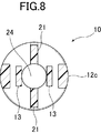
- a plurality (two in the illustrated example) of ribs 21 extending in the axial direction is formed between the base portion 12a and the top portion 12b.
- FIG. 8 which is a cross-sectional view taken along the line BB in FIG. 3, the distance between the opposing ribs 21 is slightly larger than the outer diameter of the stud 70.
- a stud receiving space 24 for receiving the stud 70 is formed by the rib 21 and the locking claw 13, and the received stud 70 is regulated so as to coincide with the axial center of the first clip 10.
- FIG. 6 which is a cross-sectional view taken along the line DD of FIG. 3, the outer side of the rib 21 is close to the axial center at the upper and lower intermediate portions and has a concave shape.
- FIG. 10 which is a cross-sectional view taken along the line FF in FIG. 3, the base portion 12 a of the inner cylinder portion 12 has a recessed portion 19 formed on the lower side of the rib 21.
- a pair of opposed arms 16b extend obliquely upward from the base of the side wall portion 12c to the inside of the stud receiving space 24.
- Each arm 16b supports a lower locking claw 13b.
- Another pair of opposing arms 16a extends obliquely upward from the middle portion of the side wall portion 12c to the inside of the stud receiving space 24.
- An upper locking claw 13a is supported on each arm 16a.
- the first clip 10 can be pushed into the stud 70 with an appropriate force.
- the locking claws 13a, b are engaged, it is difficult to come off and can be firmly fixed.
- the opposing locking claws 13a, b are offset in height relative to each other in accordance with the thread pitch of the stud 70.
- the locking claws 13a, b of the present invention can be locked to two types of studs having different screw pitches. In this embodiment, it can be locked to an M6 stud bolt having a screw pitch of 1.0 mm and a T6 stud bolt having a screw pitch of 1.6 mm.
- the upper locking claw 13a has the same shape.
- Each lower locking claw 13b has a claw tip 61b at the upper end, an intermediate claw tip 62b, and a claw tip 63b at the lower end. Between the nail tip 61b and the nail tip 62b is a valley 64b. Between the claw tip 62b and the claw tip 63b is a valley portion 65b having a flat portion longer than the valley portion 64b.
- each upper locking claw 13a has a claw tip and a trough.
- the claw tip 61b at the upper end and the claw tip 63b at the lower end can enter the thread grooves of both the M6 stud bolt and the T6 stud bolt.
- the intermediate claw tip 62b can enter the thread groove of the M6 stud bolt and can enter the portion between the threads of the T6 stud bolt.
- the locking claws 13a, b of this embodiment can be engaged with both the M6 stud bolt and the T6 stud bolt.
- a neck portion 17 having a smaller diameter than the inner cylinder portion 12 is provided between the inner cylinder portion 12 and the flange 11.
- FIG. 9 which is a cross-sectional view taken along the line CC of FIG. 4
- two pairs of convex portions 17b are formed on the inner side of the neck portion 17 at opposing positions on the rib 21.
- a pair of convex portions 17a is formed at the opposite positions.
- the studs 70a and 17b facing each other are regulated so that the stud 70 is positioned in the stud receiving space 24.
- the end portion of the top portion 12b of the inner cylinder portion 12 adjacent to the neck portion 17 is a locking shoulder 18, which acts as a connecting means for connecting the first clip 10 to the second clip 30.
- the locking shoulder 18 is formed over substantially the entire outer periphery, and when the inner cylinder portion 12 is inserted into the outer cylinder portion 32 of the second clip 30, the engagement of the outer cylinder portion 32 is achieved.
- the stop portion 39 engages with the locking shoulder 18, and the second clip 30 and the first clip 10 are connected to each other.
- a tapered portion 14 having a tapered shape is formed from the upper surface of the flange 11 to the neck portion 17 along the axial center.
- the tapered portion 14 continues to the stud through hole 15 portion of the top portion 12b of the inner cylinder portion 12.
- the stud through hole 15 has an inner diameter slightly larger than the diameter of the stud 70 and restricts the stud 70 to be positioned at the axial center of the first clip 10 but does not engage with the screw. No hole for a hexagon wrench is formed on the upper surface of the flange 11.
- the tip portion of the stud 70 can be confirmed with the naked eye. If the first clip 10 is not sufficiently engaged with the stud 70, the tip end portion of the stud 70 cannot be seen sufficiently, so that it can be immediately confirmed that the engagement is insufficient.
- the convex portions 17 a and 17 b extend from the upper surface of the flange 11 to the stud through hole.
- a tool such as a flat-blade screwdriver is inserted into the taper portion 14, the tip of the tool is hooked on the convex portion 17b or the convex portion 17a, and the entire first clip 10 including the inner cylinder portion 12 can be rotated around the axis of the stud 70. .
- the entire first clip 10 including the inner cylinder portion 12 can be rotated around the axis of the stud 70, and the locking claw 13 can be engaged with the stud 70 more strongly.
- the tightening can be released by rotating the first clip 10 reversely with a tool.
- the first clip 10 can be rotated by a tool so that the groove on the lower surface of the flange 11 can be accommodated in the protrusion of the mounting member.
- FIG. 21 is a cross-sectional view showing a state in which the attachment member 51 is attached to the attached member 52 with the stud 70 using the stud locking tool 1.
- FIG. 22 is an enlarged view of a portion J in FIG.
- On the lower surface of the flange 11, a plurality of groove portions 27 are formed side by side in a straight line.
- the groove portion 27 receives the protrusion 56 formed on the upper surface of the attachment member 51.
- Convex portions 29 are formed on both sides of the groove portion 27.
- the protrusion 56 of the mounting member engages with the groove 27 to prevent the first clip 10 from rotating about the axis of the inner cylinder 12.
- the protrusion 56 of the attachment member is engaged with the groove portion 27, when the operator removes the attachment member, the first clip 10 can be rotated, and the first clip 10 is rotated around the axis of the stud 70. And the first clip 10 can be removed from the stud 70.
- a guide portion 23 having a taper that narrows upward is formed on the base portion 12 a of the inner cylinder portion 12.
- the guide part 23 is continuous with the stud receiving space 24.
- the tip portion of the stud 70 is guided to the stud receiving space 24 by the guide portion 23 of the first clip 10, and the locking claw 13 of the first clip 10 can be engaged with the thread of the stud 70. If the angle of the guide portion 23 is too large, it is necessary to increase the distance from the base portion 12a of the first clip 10 to the arm 16, and the first clip 10 becomes large. If the angle of the guide portion 23 is too small, the tip end portion of the stud will not easily enter the entrance of the guide portion 23.
- the angle of the guide portion 23 is an angle formed by the surface of the guide portion 23 facing the axis in FIG.
- the angle of the guide portion 23 is preferably 115 to 135 °. In one embodiment, the angle of the guide portion 23 is 124 °.
- the second clip 30 will be described with reference to FIGS. 12 is a perspective view of the second clip 30, FIG. 13 is a plan view, FIG. 14 is a front view, FIG. 15 is a bottom view, and FIG. 16 is a right side view.
- the second clip 30 includes a hollow outer cylinder part 32 and a flange 31 formed at one end of the outer cylinder part 32.
- the outer cylinder part 32 accommodates the inner cylinder part 12 of the first clip 10.
- the upper surface of the flange 31 is in contact with the other surface (lower surface) of the mounting member 51.
- An elastic edge 38 extending obliquely upward is formed on the outer edge of the flange 31.
- the elastic edge portion 38 elastically presses the lower surface of the attachment member 51 toward the flange 11 of the first clip 10.
- the elastic edge portion 38 of the flange 31 is preferably formed so as to protrude from the edge portion of the flange 31 so as to be in pressure contact with the mounting member 51.
- FIG. 18 which is a sectional view taken along the line DD of FIGS. 13 and 13
- two flange holes 41 which are opposed to each other centering on the axis of the second clip 30 of the flange 31 and are elongated in the circumferential direction are formed. Has been.
- the flange hole 41 helps the elastic edge 38 to bend elastically.
- the outer cylinder part 32 is formed in a hollow cylinder having an inner diameter larger than the inner cylinder part 12 so as to receive the inner cylinder part 12 of the first clip 10.
- the outer cylinder part 32 has a locking part 39.
- the locking portion 39 acts as a second clip side connecting means for connecting the second clip 30 to the first clip 10.
- the locking part 39 is separated from the outer cylinder part 32 by a pair of side slits 34 extending in the axial direction of the outer cylinder part 32.
- FIG. 17 which is a sectional view taken along line AA in FIG. 13 and FIG. 20 which is an enlarged view of a portion C in FIG. It is separated. Therefore, the locking portion 39 is easily elastically bent.
- the engaging surface of the locking portion 39 with the locking shoulder is formed with an angle (14 ° in the embodiment), and the first clip is difficult to come off.
- the locking portion 39 becomes a locking shoulder as a connecting means of the first clip 10. Almost elastically engages 18.
- a plurality (two in the illustrated embodiment) of the locking portions 39 are provided in order to reliably maintain the connection to the first clip 10.
- FIG. 19 which is a cross-sectional view taken along the line HH in FIG. 13, in the direction where the flange hole 41 and the upper surface slit 35 do not exist with respect to the axis of the second clip 30, the flange 31 and the outer cylinder portion 32 are It is continuous.
- a plurality of ribs 37 (four in the illustrated embodiment) extending in the axial direction for increasing the strength of the outer cylinder portion 32 are formed on the outer surface of the outer cylinder portion 32. ing.
- FIG. 19 shows a cross section of the rib 37 portion.
- the stud locking tool 1 includes a second clip 30 and a first clip 10.
- the second clip 30 and the first clip 10 are connected to each other with the mounting member 51 interposed therebetween, and the mounting member 51 is clamped with a constant clamping force. Due to the clamping force, the flange 31 of the second clip 30 and the flange 11 of the first clip 10 clamp the mounting member 51 so that it does not rattle in the axial direction of the stud 70.
- the projection 56 of the mounting member 51 is pressed so as not to be disengaged from the groove 27 on the lower surface of the flange 11 of the first clip 10.
- the elastic edge portion 38 of the flange 31 prevents the mounting member 51 from rattling and prevents the first clip 10 and the second clip 30 from rotating relative to each other around the axis.
- the attachment member 51 is prevented from being detached from the attachment member 52. When the attachment member 51 expands or contracts due to a temperature change, the attachment member 51 can move in the surface direction.
- the stud locking device 1 including the first clip 10 and the second clip 30 having such a configuration is mounted so as to sandwich the mounting member 51, and then the stud locking device 1 with the stud locking device 1 is attached.
- the operation of attaching the attachment member 51 to the attached member 52 to which the stud 70 is fixed will be described.
- the inner cylinder portion 12 of the first clip 10 is positioned so that it can be inserted into the attachment hole 53 of the attachment member 51, and the outer cylinder portion 32 of the second clip 30 is It positions so that the inner cylinder part 12 inserted in the attachment hole 53 may be received.
- the first clip 10 is pushed into the mounting hole 53 so as to insert the inner cylinder portion 12.
- the second clip 30 is pushed so that the outer cylinder portion 32 accommodates the inner cylinder portion 12 of the first clip 10.
- the mounting member 51 is sandwiched between the flange 11 of the first clip 10 and the flange 31 of the second clip 30. Further, when the first clip 10 and the second clip 30 are pressed so as to press each other, the locking portion 39 of the second clip 30 is engaged with the locking shoulder 18 of the neck portion 17 of the inner cylindrical portion 12 of the first clip 10. Locked. When the locking shoulder 18 of the first clip 10 and the locking portion 39 of the second clip 30 are locked, the first clip 10 and the second clip 30 are connected to each other, and the flange 11 of the first clip 10 is connected. And the flange 31 of the second clip 30 sandwich the attachment member 51. At this time, the elastic edge portion 38 of the outer edge portion of the flange 31 of the second clip 30 presses the attachment member 51 to hold the attachment member 51 with a predetermined holding force.
- FIG. 22 is an enlarged view of a portion J in FIG.
- the mounting member 51 is sandwiched between the flange 11 of the first clip 10 and the flange 31 of the second clip 30, the protrusion formed on the mounting member 51 in the groove portion 27 on the lower surface of the flange 11 of the first clip 10. 56 are accommodated.
- the cross-sectional shape of the groove portion 27 is preferably formed in accordance with the shape of the protrusion 56.
- a convex portion 29 is formed at the edge of the groove portion 27.
- the mounting member 51 to which the stud locking device 1 is mounted in this way is carried into an assembly line of the vehicle.
- the assembling worker positions the mounting member 51 to which the stud locking tool 1 is mounted at a predetermined position of the mounted member 52 such as an automobile panel.
- the mounting member 51 is positioned so that each of the plurality of studs 70 fixed to the mounted member 52 is received in the hollow portion of the inner cylindrical portion 12 of the first clip 10 of the stud locking tool 1. Since the stud locking device 1 is pre-attached to the mounting member 51, the operator does not have the work of holding the stud locking device 1, and concentrates on the work of positioning the stud locking device 1 of the mounting member 51 on the stud 70. be able to. At the time of positioning, the leading end of the stud 70 can be easily guided to the stud receiving space 24 of the first clip 10 using the guide portion 23 of the first clip 10.
- the mounting member 51 is pressed against the mounted member 52 so that the stud 70 is received in the stud receiving space 24 inside the inner cylindrical portion 12 of the first clip 10.
- the stud 70 is inserted into the stud receiving space 24, and the locking claw 13 formed on the inner side of the inner cylinder portion 12 bends outward to receive the stud 70.
- the locking claw 13 slides on the screw on the side surface of the stud 70.
- the locking claw 13 stops sliding and engages with the thread of the stud 70, so that the attaching member 51 becomes the attached member 52. Fixed to.
- attachment member 51 After the attachment member 51 is attached to the attachment member 52, a flathead screwdriver is further inserted into the taper portion 14 of the flange 11 of the first clip 10, and the first clip 10 is rotated about the axis of the stud 70, The clip 10 can be further tightly engaged with the locking claw 13.
- the attachment member 51 can be removed from the attached member 52 by inserting a flathead screwdriver into the tapered portion 14 of the first clip 10 to reverse the first clip 10 to release the tightening.
- FIG. 23 is a cross-sectional view showing a state in which the stud locking tool of FIG. 21 is attached to a stud having an incomplete thread portion.
- the stud 70 has an incomplete threaded portion 71 formed in a portion close to the base portion.
- the incomplete thread portion 71 has a shape in which the thread is slightly crushed.
- the attachment member 51 may be attached to the stud 70 with a nut instead of a stud locking tool.
- an incomplete thread portion 71 is provided.
- the incomplete thread portion 72 can be formed when the thread of the stud 70 is formed.
- the latching claw 13 that latches to the stud 70 is provided in two stages in the vertical direction.
- the incomplete thread 71 is at the base of the stud 70 and the incomplete thread 72 is near the tip of the stud 70.
- the upper locking claw 13a and the lower locking claw 13b that make a pair are largely shifted in the vertical direction, so that the claw tip of the upper locking claw 13a abuts the thread of the incomplete screw portion 72.
- the claw tip of the upper locking claw 13a is less likely to come into contact with the thread of the incomplete thread 72, and The claw tip of the side locking claw 13b is less likely to come into contact with the thread of the incomplete screw portion 71.
- the height lb to the upper claw tip 61b of the lower one of the pair of lower claw 13b (the left side in FIG. 23) is capped. It is 9.6 mm from the upper surface of the mounting member (conventional 8.6 mm). For this reason, the lower locking claw 13b is less likely to come into contact with the lower incomplete screw portion 71.
- the height la of the upper claw tip 61a of the upper one of the pair of upper locking claws 13a (the right side in FIG. 23) from the upper surface of the mounted member 52 is 15.1 mm (previously 16.1 mm). Therefore, the upper locking claw 13a is less likely to contact the upper incomplete screw portion 72.
- the distance la-lb from the upper claw tip 61b of the lower lower locking claw 13b to the upper claw tip 61a of the higher upper locking claw 13a is 5.5 mm (previously 7.5 mm).
- the tips 61, 62, 63 are difficult to contact the incomplete threaded portions 71, 72.
- the mounting member 51 is sandwiched between the flange 11 of the first clip and the flange 31 of the second clip, and the stud 70 is placed in the stud receiving space 24 inside the inner cylinder portion 12 of the first clip 10. And the engaging claw 13 is engaged with the thread of the stud 70, so that the attaching member 51 can be easily and securely attached to the attached member 52. Further, since the head of the stud 70 can be seen from the taper portion 14, it can be easily confirmed whether or not the first clip 10 is completely attached to the stud 70.
Landscapes
- Engineering & Computer Science (AREA)
- General Engineering & Computer Science (AREA)
- Mechanical Engineering (AREA)
- Chemical & Material Sciences (AREA)
- Combustion & Propulsion (AREA)
- Transportation (AREA)
- Snaps, Bayonet Connections, Set Pins, And Snap Rings (AREA)
- Connection Of Plates (AREA)
- Body Structure For Vehicles (AREA)
Priority Applications (3)
| Application Number | Priority Date | Filing Date | Title |
|---|---|---|---|
| CN201380051258.8A CN104685230B (zh) | 2012-08-15 | 2013-08-09 | 螺柱卡止件 |
| EP13879311.2A EP2886885B1 (en) | 2012-08-15 | 2013-08-09 | Stud locking tool |
| US14/619,824 US9500219B2 (en) | 2012-08-15 | 2015-02-11 | Stud locking device |
Applications Claiming Priority (2)
| Application Number | Priority Date | Filing Date | Title |
|---|---|---|---|
| JP2012180019A JP5978541B2 (ja) | 2012-08-15 | 2012-08-15 | スタッド係止具 |
| JP2012-180019 | 2012-08-15 |
Related Child Applications (1)
| Application Number | Title | Priority Date | Filing Date |
|---|---|---|---|
| US14/619,824 Continuation US9500219B2 (en) | 2012-08-15 | 2015-02-11 | Stud locking device |
Publications (1)
| Publication Number | Publication Date |
|---|---|
| WO2014027625A1 true WO2014027625A1 (ja) | 2014-02-20 |
Family
ID=50685582
Family Applications (1)
| Application Number | Title | Priority Date | Filing Date |
|---|---|---|---|
| PCT/JP2013/071691 Ceased WO2014027625A1 (ja) | 2012-08-15 | 2013-08-09 | スタッド係止具 |
Country Status (6)
| Country | Link |
|---|---|
| US (1) | US9500219B2 (https=) |
| EP (1) | EP2886885B1 (https=) |
| JP (1) | JP5978541B2 (https=) |
| CN (1) | CN104685230B (https=) |
| TW (1) | TWI600838B (https=) |
| WO (1) | WO2014027625A1 (https=) |
Cited By (1)
| Publication number | Priority date | Publication date | Assignee | Title |
|---|---|---|---|---|
| CN105564329A (zh) * | 2016-02-04 | 2016-05-11 | 成都银利汽车零部件有限公司 | 支撑调节装置 |
Families Citing this family (23)
| Publication number | Priority date | Publication date | Assignee | Title |
|---|---|---|---|---|
| USD708953S1 (en) | 2013-03-15 | 2014-07-15 | The Folger Coffee Company | Container |
| JP5945661B1 (ja) * | 2015-06-23 | 2016-07-05 | 和富 岡 | 雌ねじ部品、雄ねじ部品及び座金部品 |
| JP6533110B2 (ja) * | 2015-07-14 | 2019-06-19 | 日立オムロンターミナルソリューションズ株式会社 | 穴キャップ |
| KR101765631B1 (ko) * | 2015-12-14 | 2017-08-07 | 현대자동차 주식회사 | 차량용 체결 클립 |
| DE102016212350B4 (de) * | 2016-07-06 | 2020-09-24 | Hansgrohe Se | Schraubverbindung und Sanitärinstallationsanschlussbox |
| EP3339664B1 (de) * | 2016-12-21 | 2021-09-15 | Newfrey LLC | Befestigungselement, anordnung mit einem befestigungselement und einbauverfahren eines befestigungselements |
| CN107339308A (zh) * | 2016-12-28 | 2017-11-10 | 安徽江淮汽车集团股份有限公司 | 一种双螺纹连接可预装卡扣 |
| JP6851850B2 (ja) | 2017-02-16 | 2021-03-31 | ポップリベット・ファスナー株式会社 | シート状部材の取付具 |
| TWI685699B (zh) | 2018-05-11 | 2020-02-21 | 友達光電股份有限公司 | 背光模組及連接座 |
| KR101978424B1 (ko) * | 2018-05-21 | 2019-05-14 | 주식회사 에이티에스 | 와셔 조립체 및 와셔 조립체의 조립 방법 |
| JP6869924B2 (ja) * | 2018-07-23 | 2021-05-12 | ポップリベット・ファスナー株式会社 | スタッド係止具 |
| WO2020059680A1 (ja) * | 2018-09-18 | 2020-03-26 | 株式会社パイオラックス | 留め具 |
| EP3850147B1 (en) | 2018-11-14 | 2022-06-15 | Samsung Electronics Co., Ltd. | Water transmission device and washing machine including the same |
| KR102701618B1 (ko) | 2018-12-27 | 2024-09-03 | 삼성전자주식회사 | 스터드 |
| US11486422B2 (en) * | 2019-03-27 | 2022-11-01 | Illinois Tool Works Inc. | Adaptable push-on stud fastener |
| KR102141902B1 (ko) * | 2019-05-15 | 2020-08-06 | 주식회사 니프코코리아 | 자동차용 푸시너트 |
| KR102791564B1 (ko) * | 2019-12-16 | 2025-04-03 | 현대자동차주식회사 | 차량의 툴케이스 고정 구조 |
| DE102020117633A1 (de) | 2020-07-03 | 2022-01-05 | hmg gmbh | Vorrichtung zur Herstellung von Steckverbindungen, Verfahren zur Herstellung der Steckverbindungen und Verwendung der Vorrichtung |
| EP4421333B1 (en) * | 2021-03-22 | 2026-02-25 | Newfrey LLC | Fastener and arrangement comprising a fastener |
| CN115199634A (zh) * | 2021-04-09 | 2022-10-18 | 伊利诺斯工具制品有限公司 | 连接件 |
| USD992404S1 (en) * | 2021-08-16 | 2023-07-18 | Gripple Limited | Anchor device |
| USD994478S1 (en) * | 2021-08-16 | 2023-08-08 | Gripple Limited | Anchor device |
| US12553569B2 (en) * | 2024-06-24 | 2026-02-17 | Progress Rail Locomotive Inc. | Mounting system for equipment |
Citations (6)
| Publication number | Priority date | Publication date | Assignee | Title |
|---|---|---|---|---|
| JPH07174127A (ja) * | 1993-12-17 | 1995-07-11 | Tougou Seisakusho:Kk | 保持具 |
| JPH11141528A (ja) * | 1997-11-10 | 1999-05-25 | Pop Rivet Fastener Kk | スタッド係止具 |
| JP2007292146A (ja) | 2006-04-24 | 2007-11-08 | Nippon Pop Rivets & Fasteners Ltd | アンダーカバー等の固定具及び取付装置 |
| JP2009096252A (ja) * | 2007-10-15 | 2009-05-07 | Nippon Pop Rivets & Fasteners Ltd | 空力性能向上用空力カバーの取付構造 |
| JP2009162357A (ja) | 2008-01-10 | 2009-07-23 | Hitachi Ltd | 自動変速機の制御方法及び制御装置 |
| EP2131084A2 (en) * | 2008-06-06 | 2009-12-09 | Newfrey LLC | Fastening element for fastening a structural part to a pin |
Family Cites Families (15)
| Publication number | Priority date | Publication date | Assignee | Title |
|---|---|---|---|---|
| JPS602334Y2 (ja) * | 1980-07-15 | 1985-01-23 | 株式会社ニフコ | ナツト |
| US4850778A (en) * | 1988-07-27 | 1989-07-25 | Trw, Inc. | Push-on fastener |
| JP2524861Y2 (ja) * | 1991-12-09 | 1997-02-05 | 矢崎総業株式会社 | ボルト係止用の係止部構造 |
| FR2704027B1 (fr) | 1993-04-13 | 1995-12-01 | Trw Carr France Sa | Elément de retenue, notamment pour carroseries de véhicules automobiles. |
| FR2733817B1 (fr) * | 1995-05-03 | 1997-08-01 | Comet | Piece de fixation a monter sur un goujon crante |
| US5660513A (en) * | 1995-07-19 | 1997-08-26 | Illinois Tool Works Inc. | Stud clip having different insertion/withdrawal forces |
| FR2786845B1 (fr) * | 1998-12-02 | 2001-01-26 | Rapid Sa | Attache de fixation notamment pour cables, tuyauteries ou analogues |
| FR2873771B1 (fr) * | 2004-07-30 | 2008-08-15 | I T W De France Sas | Attache femelle et obturateur la comportant |
| US20060099049A1 (en) * | 2004-11-05 | 2006-05-11 | Peterson Rex J | Fastener/stud retainer |
| DE102005015033A1 (de) * | 2005-03-31 | 2006-10-05 | Newfrey Llc, Newark | Befestigungselement zur Anbringung auf einem Gewindebolzen |
| JP2009162358A (ja) | 2008-01-10 | 2009-07-23 | Daiwa Kasei Ind Co Ltd | スタッドボルト用固定クリップ |
| GB0804196D0 (en) * | 2008-03-06 | 2008-04-16 | Newfrey Llc | Fastener for automotive components |
| JP4789967B2 (ja) * | 2008-04-14 | 2011-10-12 | 株式会社ニフコ | 物品保持具 |
| DE202009011986U1 (de) | 2009-08-28 | 2009-12-10 | Illinois Tool Works Inc., Glenview | Vorrichtung zur Verbindung zweier Bauteile |
| JP5824031B2 (ja) * | 2010-04-02 | 2015-11-25 | イリノイ トゥール ワークス インコーポレイティド | 防振用の車両取り付けアセンブリ |
-
2012
- 2012-08-15 JP JP2012180019A patent/JP5978541B2/ja active Active
-
2013
- 2013-08-09 EP EP13879311.2A patent/EP2886885B1/en active Active
- 2013-08-09 WO PCT/JP2013/071691 patent/WO2014027625A1/ja not_active Ceased
- 2013-08-09 CN CN201380051258.8A patent/CN104685230B/zh active Active
- 2013-08-15 TW TW102129363A patent/TWI600838B/zh active
-
2015
- 2015-02-11 US US14/619,824 patent/US9500219B2/en active Active
Patent Citations (6)
| Publication number | Priority date | Publication date | Assignee | Title |
|---|---|---|---|---|
| JPH07174127A (ja) * | 1993-12-17 | 1995-07-11 | Tougou Seisakusho:Kk | 保持具 |
| JPH11141528A (ja) * | 1997-11-10 | 1999-05-25 | Pop Rivet Fastener Kk | スタッド係止具 |
| JP2007292146A (ja) | 2006-04-24 | 2007-11-08 | Nippon Pop Rivets & Fasteners Ltd | アンダーカバー等の固定具及び取付装置 |
| JP2009096252A (ja) * | 2007-10-15 | 2009-05-07 | Nippon Pop Rivets & Fasteners Ltd | 空力性能向上用空力カバーの取付構造 |
| JP2009162357A (ja) | 2008-01-10 | 2009-07-23 | Hitachi Ltd | 自動変速機の制御方法及び制御装置 |
| EP2131084A2 (en) * | 2008-06-06 | 2009-12-09 | Newfrey LLC | Fastening element for fastening a structural part to a pin |
Non-Patent Citations (1)
| Title |
|---|
| See also references of EP2886885A4 |
Cited By (1)
| Publication number | Priority date | Publication date | Assignee | Title |
|---|---|---|---|---|
| CN105564329A (zh) * | 2016-02-04 | 2016-05-11 | 成都银利汽车零部件有限公司 | 支撑调节装置 |
Also Published As
| Publication number | Publication date |
|---|---|
| TW201418587A (zh) | 2014-05-16 |
| US9500219B2 (en) | 2016-11-22 |
| EP2886885B1 (en) | 2017-09-27 |
| CN104685230A (zh) | 2015-06-03 |
| JP2015121234A (ja) | 2015-07-02 |
| JP5978541B2 (ja) | 2016-08-24 |
| EP2886885A4 (en) | 2016-03-30 |
| CN104685230B (zh) | 2017-03-08 |
| US20150152910A1 (en) | 2015-06-04 |
| TWI600838B (zh) | 2017-10-01 |
| EP2886885A1 (en) | 2015-06-24 |
Similar Documents
| Publication | Publication Date | Title |
|---|---|---|
| JP5978541B2 (ja) | スタッド係止具 | |
| JP4850573B2 (ja) | アンダーカバー等の固定具及び取付装置 | |
| JP4276196B2 (ja) | 車両用ルーフアンテナ取付け装置 | |
| US8113093B2 (en) | Combination wrench socket | |
| US6824203B2 (en) | Apparatus and method for attaching undercover onto underside of car floor panel | |
| US20080141501A1 (en) | Clip | |
| JP2015121234A5 (https=) | ||
| KR102363136B1 (ko) | 자동차 조립을 위한 록킹 리테이너 시스템 | |
| US11255365B2 (en) | Fastener assembly | |
| US10197089B2 (en) | Clip and clip attaching structure | |
| JP2587328Y2 (ja) | パイプ保持具 | |
| US11493078B2 (en) | Stud locking tool | |
| JPH0645184U (ja) | パイプ保持具 | |
| WO2015049909A1 (ja) | スタッド係止具 | |
| JP2009162358A (ja) | スタッドボルト用固定クリップ | |
| JP2005090681A (ja) | クリップ | |
| JP4971247B2 (ja) | スタッドボルト用固定クリップ | |
| JP6322447B2 (ja) | 取付部材の固定構造 | |
| JP5952712B2 (ja) | 取付具および車両外装部材の取付構造 | |
| JP2019034615A (ja) | 自動車用工具の収納構造 | |
| JPH0519661Y2 (https=) | ||
| KR20230006626A (ko) | 조립형 마운팅-볼트 유닛 | |
| JPH07243416A (ja) | スタッド固定具 | |
| WO2018237362A1 (en) | A bushing used for a nut fastening clamp assembly | |
| JP2009180306A (ja) | スタッドボルト等のボルト係止具 |
Legal Events
| Date | Code | Title | Description |
|---|---|---|---|
| 121 | Ep: the epo has been informed by wipo that ep was designated in this application |
Ref document number: 13879311 Country of ref document: EP Kind code of ref document: A1 |
|
| NENP | Non-entry into the national phase |
Ref country code: DE |
|
| REEP | Request for entry into the european phase |
Ref document number: 2013879311 Country of ref document: EP |
|
| WWE | Wipo information: entry into national phase |
Ref document number: 2013879311 Country of ref document: EP |
|
| NENP | Non-entry into the national phase |
Ref country code: JP |