WO2014027489A1 - 運転支援装置 - Google Patents
運転支援装置 Download PDFInfo
- Publication number
- WO2014027489A1 WO2014027489A1 PCT/JP2013/064045 JP2013064045W WO2014027489A1 WO 2014027489 A1 WO2014027489 A1 WO 2014027489A1 JP 2013064045 W JP2013064045 W JP 2013064045W WO 2014027489 A1 WO2014027489 A1 WO 2014027489A1
- Authority
- WO
- WIPO (PCT)
- Prior art keywords
- image
- vehicle
- displayed
- display
- monitor
- Prior art date
- Legal status (The legal status is an assumption and is not a legal conclusion. Google has not performed a legal analysis and makes no representation as to the accuracy of the status listed.)
- Ceased
Links
Images





Classifications
-
- B—PERFORMING OPERATIONS; TRANSPORTING
- B60—VEHICLES IN GENERAL
- B60R—VEHICLES, VEHICLE FITTINGS, OR VEHICLE PARTS, NOT OTHERWISE PROVIDED FOR
- B60R1/00—Optical viewing arrangements; Real-time viewing arrangements for drivers or passengers using optical image capturing systems, e.g. cameras or video systems specially adapted for use in or on vehicles
- B60R1/20—Real-time viewing arrangements for drivers or passengers using optical image capturing systems, e.g. cameras or video systems specially adapted for use in or on vehicles
- B60R1/22—Real-time viewing arrangements for drivers or passengers using optical image capturing systems, e.g. cameras or video systems specially adapted for use in or on vehicles for viewing an area outside the vehicle, e.g. the exterior of the vehicle
- B60R1/23—Real-time viewing arrangements for drivers or passengers using optical image capturing systems, e.g. cameras or video systems specially adapted for use in or on vehicles for viewing an area outside the vehicle, e.g. the exterior of the vehicle with a predetermined field of view
- B60R1/26—Real-time viewing arrangements for drivers or passengers using optical image capturing systems, e.g. cameras or video systems specially adapted for use in or on vehicles for viewing an area outside the vehicle, e.g. the exterior of the vehicle with a predetermined field of view to the rear of the vehicle
-
- B—PERFORMING OPERATIONS; TRANSPORTING
- B60—VEHICLES IN GENERAL
- B60R—VEHICLES, VEHICLE FITTINGS, OR VEHICLE PARTS, NOT OTHERWISE PROVIDED FOR
- B60R11/00—Arrangements for holding or mounting articles, not otherwise provided for
- B60R11/04—Mounting of cameras operative during drive; Arrangement of controls thereof relative to the vehicle
-
- G—PHYSICS
- G01—MEASURING; TESTING
- G01C—MEASURING DISTANCES, LEVELS OR BEARINGS; SURVEYING; NAVIGATION; GYROSCOPIC INSTRUMENTS; PHOTOGRAMMETRY OR VIDEOGRAMMETRY
- G01C21/00—Navigation; Navigational instruments not provided for in groups G01C1/00 - G01C19/00
- G01C21/26—Navigation; Navigational instruments not provided for in groups G01C1/00 - G01C19/00 specially adapted for navigation in a road network
- G01C21/34—Route searching; Route guidance
- G01C21/36—Input/output arrangements for on-board computers
- G01C21/3697—Output of additional, non-guidance related information, e.g. low fuel level
-
- G—PHYSICS
- G08—SIGNALLING
- G08G—TRAFFIC CONTROL SYSTEMS
- G08G1/00—Traffic control systems for road vehicles
- G08G1/16—Anti-collision systems
- G08G1/166—Anti-collision systems for active traffic, e.g. moving vehicles, pedestrians, bikes
-
- H—ELECTRICITY
- H04—ELECTRIC COMMUNICATION TECHNIQUE
- H04N—PICTORIAL COMMUNICATION, e.g. TELEVISION
- H04N7/00—Television systems
- H04N7/18—Closed-circuit television [CCTV] systems, i.e. systems in which the video signal is not broadcast
-
- B—PERFORMING OPERATIONS; TRANSPORTING
- B60—VEHICLES IN GENERAL
- B60R—VEHICLES, VEHICLE FITTINGS, OR VEHICLE PARTS, NOT OTHERWISE PROVIDED FOR
- B60R2300/00—Details of viewing arrangements using cameras and displays, specially adapted for use in a vehicle
- B60R2300/70—Details of viewing arrangements using cameras and displays, specially adapted for use in a vehicle characterised by an event-triggered choice to display a specific image among a selection of captured images
-
- G—PHYSICS
- G06—COMPUTING OR CALCULATING; COUNTING
- G06V—IMAGE OR VIDEO RECOGNITION OR UNDERSTANDING
- G06V10/00—Arrangements for image or video recognition or understanding
- G06V10/10—Image acquisition
- G06V10/12—Details of acquisition arrangements; Constructional details thereof
- G06V10/14—Optical characteristics of the device performing the acquisition or on the illumination arrangements
- G06V10/143—Sensing or illuminating at different wavelengths
-
- G—PHYSICS
- G06—COMPUTING OR CALCULATING; COUNTING
- G06V—IMAGE OR VIDEO RECOGNITION OR UNDERSTANDING
- G06V20/00—Scenes; Scene-specific elements
- G06V20/50—Context or environment of the image
- G06V20/56—Context or environment of the image exterior to a vehicle by using sensors mounted on the vehicle
- G06V20/58—Recognition of moving objects or obstacles, e.g. vehicles or pedestrians; Recognition of traffic objects, e.g. traffic signs, traffic lights or roads
Definitions
- the present invention relates to a drive assist device for a vehicle.
- the present application claims priority based on Japanese Patent Application No. 2012-181060 filed in Japan on August 17, 2012 and Japanese Patent Application No. 2012-181062 filed in Japan on August 17, 2012, The contents are incorporated herein.
- Patent Document 1 discloses a configuration in which an external video image is continuously displayed for a predetermined time after the turn-off operation when the turn-off switch is turned off. According to this configuration, even when the winker switch is turned off before the left / right movement (lane movement, right / left turn, etc.) of the own vehicle is completed, the external image is displayed on the monitor until the left / right movement of the own vehicle is completed. It is considered possible to keep displaying.
- a monitor for displaying an image of various information is installed at a position in a vehicle cabin where the driver can visually recognize.
- a route guidance image by a navigation device, an external world image captured by an external camera capturing an area behind the vehicle, and the like are displayed.
- Patent Document 2 describes a configuration in which a warning image is displayed on the above-described monitor when an obstacle is detected in a rear side area of a vehicle.
- a map image or the like of the navigation device is displayed on the monitor described above, and the map image is switched to the outside image in response to the turn-on operation of the blinker switch.
- the external image is displayed on the monitor until a predetermined time has elapsed since the turn-off operation of the blinker switch. Therefore, immediately after moving to one side among right and left, when moving to the other side etc., the map image etc. of a navigation apparatus can not be confirmed.
- the aspect of the present invention has been made in consideration of the above-mentioned circumstances, and it is possible to display an optimal image on the display unit even when changing lanes or turning left or right again immediately after changing lanes or turning left or right It aims to provide a driving support device that can
- the structure which superimposes and displays a warning image on the image (for example, a route guidance image, an external video etc.) already displayed on the monitor can be considered.
- the external image when the warning image is superimposed and displayed, the obstacle appearing in the external image and the warning image overlap on the monitor, which may make it impossible to check the obstacle through the monitor. is there.
- Another aspect of the present invention is made in consideration of the above-mentioned circumstances, and provides a driving support device capable of displaying a warning image in an optimal state according to an image already displayed on the display unit.
- the purpose is to
- the driving support device adopts the following.
- a photographing unit capable of photographing a dead area provided on the side mirror on the second side and being adjacent to the rear side area of the vehicle and the rear side area and outside the visible range of the side mirror on the second side;
- a display unit configured to display an image captured by an imaging unit so that a driver of the vehicle can visually recognize the image; and a blinker switch that signals movement of the vehicle to the first side or the second side.
- the display unit displays the image in response to the turn-on operation of the blinker switch indicating movement of the vehicle to the second side, and turns off the display of the image after a predetermined time has elapsed from the turn-off operation of the blinker switch. And the vehicle is ahead within the predetermined time If it is predicted that moves in the first side, to turn off the display of the image before the predetermined time period elapses.
- the display unit is configured to move to the first side within the predetermined time after the turn-off operation indicating the movement of the vehicle to the second side is performed.
- the display of the image may be turned off before the predetermined time elapses when the turn-on switch indicating the movement of the vehicle is turned on.
- the display unit is configured to turn off the blinker switch indicating the movement of the vehicle to the second side, and then the route guidance information from the navigation device When it is predicted that the vehicle moves to the first side within the predetermined time, display of the image may be turned off before the predetermined time elapses.
- the display unit displays a warning image for giving a warning to the driver when there is an obstacle around the vehicle, and the image is When displayed, the warning image, which is smaller than the case where the video is not displayed, may be displayed superimposed on the video.
- the warning image when the video is not displayed is displayed at a position including the central portion of the screen in the display unit, and the warning when the video is displayed
- the image may be displayed close to the vehicle side among the images displayed on the display unit.
- the winker switch is turned off before the movement of the vehicle to the first side or the second side (lane change, left / right turn, etc.) is completed.
- the image captured by the imaging unit can be continuously confirmed until the movement to the first side or the second side is completed.
- the movement to the first side or the second side is already completed when the blinker switch is turned off, the operation of the following vehicle after the movement to the first side or the second side is displayed. You can check through the department.
- the display of the image is turned off before the predetermined time elapses, for example, the display unit
- the image displayed by can be switched to a navigation image etc., and route guidance can be confirmed promptly. Therefore, the optimum image can be displayed on the display unit, and the convenience can be improved.
- the vehicle moves to the second side based on the turn-on operation of the blinker switch indicating the movement of the vehicle to the first side, subsequently to the first side within a predetermined time It can be predicted to move. Then, in this case, by turning off the display of the video, for example, the video displayed by the display unit can be switched to a navigation image or the like, and route guidance can be promptly confirmed.
- the vehicle moves to the second side and then moves to the first side within a predetermined time after moving to the second side. it can. Then, in this case, by turning off the display of the video, for example, the video displayed by the display unit can be switched to a navigation image or the like, and route guidance can be promptly confirmed.
- the warning image can be displayed in an optimal state according to the image displayed on the display unit.
- the driver when the external image is not displayed, the driver can be reliably notified of the presence of an obstacle around the vehicle by displaying a warning image at the center of the screen.
- the central portion of the screen of the external video image displayed on the display unit is displayed by displaying the warning image by moving it to the vehicle side among the external video images displayed on the display unit. Parts) can be prevented from being covered by the warning image. That is, since the warning image is displayed at a position not disturbing the viewing of the external video, the driver can be notified of the presence of an obstacle around the vehicle after securing the visibility of the external video.
- the warning image is displayed at a position not disturbing the viewing of the external video
- the driver can be notified of the presence of an obstacle around the vehicle after securing the visibility of the external video.
- the driver's seat side is set as a first side
- the opposite side (front passenger seat side) of the first side is set as a second side in the vehicle width direction of the vehicle.
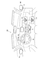
- FIG. 1 is a block diagram of a driving support device, and is a front view looking forward from the passenger compartment.
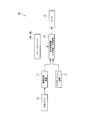
- FIG. 2 is a block diagram of the driving support device.
- the driving support apparatus 10 in the present embodiment includes the navigation device 11, an external camera (shooting unit) 13, blinker switches 14R and 14L, a monitor (display unit) 15, and a side.
- the mirrors 16R and 16L, the image processing device 17, and the display switching device (display unit) 18 are provided.
- the navigation device 11 receives a positioning signal such as a GPS (Global Positioning System) signal, and detects the current position of the vehicle based on the positioning signal.
- the GPS signal is, for example, a positioning signal for measuring the position of the vehicle using a satellite. Further, the navigation device 11 can detect the current position of the own vehicle by using the calculation processing of the autonomous navigation based on the velocity and the yaw rate of the own vehicle.
- the navigation device 11 also stores map data for displaying a map on a display screen of, for example, the monitor 15 or the like.
- the map data includes, for example, road coordinate data and road data.
- the road coordinate data indicates, for example, position coordinates on the road required for the process of map matching based on the current position of the vehicle.
- Road data is, for example, data required for processing such as route search and route guidance.
- the road data is, for example, a node which is a coordinate point consisting of latitude and longitude of a predetermined position on the road such as an intersection and a branch point, a link which is a line connecting between the nodes, a road shape, a road type, a road Data and speed limits.
- the navigation device 11 performs map matching on the map data based on, for example, the information of the current position of the vehicle, and controls the display of the map on the monitor 15 and the current position of the vehicle. Further, the navigation device 11 executes, for example, processing such as route search and route guidance, and outputs navigation image data such as route guidance information to a destination or a transit point to the display switching device 18 together with road data.
- the external camera 13 is configured of, for example, a CCD camera or a CMOS camera capable of imaging in a visible light region, an infrared region, or the like.
- the external camera 13 is disposed below the left side mirror 16L (the side mirror 16L opposite to the driver's seat side (the passenger side)) of the left and right side mirrors 16R, 16L.
- the external camera 13 is disposed below the second side side mirror 16L.
- the external camera 13 includes a wide-angle lens, and captures an external image of a predetermined wide-angle area from the left side to the rear of the host vehicle.
- the external camera 13 performs predetermined image processing such as filtering and binarization processing on a video obtained by photographing, generates image data including pixels of a two-dimensional array, and outputs the image data to the image processing device 17 .
- the detection target area Z of the external camera 13 is, as shown in FIG. 3, a rear side area Z1 of the vehicle which is a visible range of the left side mirror 16L and a left side mirror 16L adjacent to the rear side area Z1. And a blind spot area Z2 outside the visible range.
- the viewing angle is about 27 ° in the rear side region Z1, and the viewing angle is about 82 ° in the dead angle region Z2, for example.
- the overlapping area with the vehicle is set to be, for example, about 1 to 2 ° in a viewing angle.
- the blinker switches 14R and 14L are lever switches that signal, for example, the movement of the host vehicle on the first side or the second side to surrounding vehicles. Specifically, the blinker switches 14R and 14L can be switched on and off by tilting the blinker lever 21 disposed in front of the steering wheel 20 in the corresponding direction (counterclockwise or clockwise). It has become.
- the left winker switch 14L the second winker switch
- the left winker lamp (Not shown) flashes.
- the right side blinker switch 14R (the first side blinker switch) is turned on (tilt operation of the blinker lever 21 clockwise)
- the right side blinker lamp (not shown) blinks.
- the winker switches 14R and 14L are turned off, that is, when the steering wheel 20 returns by a predetermined steering angle or more after lane change or left / right turn, or the winker lever 21 is tilted from its own position by its own operation. When it is forcibly returned to the neutral position, the blinking of the blinker lamp ends.
- the monitor 15 is configured of, for example, a 5 to 8 inch liquid crystal display device provided in the navigation device 11.
- the monitor 15 is provided at a position (for example, approximately the center in the vehicle width direction of the instrument panel) visible by the driver.
- the image processing device 17 performs enlargement and compression processing on the image data input from the external camera 13, and outputs the image data after image processing to the display switching device 18.
- the display switching device 18 selectively switches whether to display the navigation image input from the navigation device 11 or the external video input from the image processing device 17 on the monitor 15. For example, the display switching device 18 determines whether the external video is necessary. The display switching device 18 displays the navigation image on the monitor 15 when it is determined that the external video is not necessary, and switches from the navigation image to the external video when it is determined that the external video is necessary.
- the display switching device 18 detects the on operation of the left winker switch 14L (the second winker switch) among the left and right winker switches 14R and 14L, the driver changes the lane to the left lane or turns left Predict that you have the intention to execute, or actually detect that your vehicle is performing a lane change or a left turn. In this case, it is determined that the external video is required, and the external video is displayed on the monitor 15. On the other hand, when the display switching device 18 detects that the driver turns off the left blinker switch 14L, the display switching device 18 determines that the external video is not necessary, and monitors the monitor 15 after a predetermined time (for example, about 2 seconds) elapses. Switch the video of to the navigation image.
- a predetermined time for example, about 2 seconds
- FIG. 4 is a flowchart for explaining the display switching method. In the following description, when the external video is not displayed on the monitor 15, the navigation image is always displayed.
- step S1 it is determined whether the left blinker switch 14L (the blinker switch on the second side) has been turned on.
- step S1 If the result of the determination in step S1 is "NO” (if the left blinker switch 14L is not turned on), it is determined that the driver has no intention to change lanes to the left lane or left turn. Repeat the routine. On the other hand, when the determination result in step S1 is "YES" (when the left winker switch 14L is turned on), lane change to the left lane or left turn is being executed, or driver change to the left lane or left turn It is determined that there is an intention to execute the process, and the process proceeds to step S2.
- step S ⁇ b> 2 the display switching device 18 displays the external video image input from the image processing device 17 on the monitor 15. Thereby, the driver can execute the lane change to the left lane and the left turn while confirming the situation captured in the side mirror 16L and the external image displayed on the monitor 15.
- step S3 it is determined whether the left blinker switch 14L has been turned off. If the result of the determination in step S3 is "NO" (if the left winker switch 14L is not turned off), the left blinker switch 14L is still on, that is, the vehicle is still changing lanes or turning left. It is determined that the image is still necessary, and the routine of step S3 is repeated. On the other hand, when the determination result in step S3 is "YES" (when the left blinker switch 14L is turned off), the process proceeds to step S4.
- step S4 it is determined whether or not a predetermined time (for example, about 2 seconds) has elapsed since the left winker switch 14L is turned off. If the determination result in step S4 is "YES" (if the predetermined time has elapsed), it is determined that the external video is not necessary, and the process proceeds to step S5 to turn off the display of the external video. In this case, the display switching device 18 switches the video displayed on the monitor 15 from the external video to the navigation image. That is, after a predetermined time elapses from the turning-off operation of the left winker switch 14L, it is determined that the lane change and the left turn are completed, and the video on the monitor 15 is returned to the navigation image.
- a predetermined time for example, about 2 seconds
- step S4 determines whether the lane change or the left turn has not been completed although the left blinker switch 14L has been turned off. Go to S6.
- step S6 it is determined whether the turn-on operation of the right-side winker switch 14R (the first-side winker switch) or the route guidance of the right turn from the navigation device 11 is present. That is, based on the on operation of the right blinker switch 14R or the route guidance from the navigation device 11 whether it is necessary to change the lane to the right before the predetermined time elapses or to turn right after the left blinker switch 14L is turned off. To judge.
- step S6 If the result of the determination in step S6 is "NO", that is, if the right-handed blinker switch 14R is not turned on or there is no route guidance from the navigation device 11, the process proceeds to step S7 and the display of the outside world image is continued. In this case, the process returns to step S4, and the above-described routine is repeated.
- step S6 determines whether there is an on operation of the right blinker switch 14R or route guidance from the navigation device 11. If the result of the determination in step S6 is "YES", that is, if there is an on operation of the right blinker switch 14R or route guidance from the navigation device 11, the process proceeds to step S5. In this case, the display of the external video is turned off, and the video displayed on the monitor 15 is switched to the navigation image. Thus, the routine ends.
- the external image is continuously displayed for a predetermined time after the left winker switch 14L is turned off.
- the left blinker switch 14L is turned off before the movement of the vehicle to the first side or the second side is completed, such as a lane change
- the first side or the first side of the vehicle The external image can be continuously checked until the movement to the two side is completed. Further, when the lane change or the like has already been completed when the left blinker switch 14L is turned off, the operation of the following vehicle such as after the lane change can be confirmed through the monitor 15.
- the display of the external image is turned off before the predetermined time elapses. did.
- the image displayed on the monitor 15 can be switched from the external image to the navigation image when the right turn or the like is made before the predetermined time elapses after the left blinker switch 14L is turned off. Therefore, it is possible to quickly confirm the route guidance after changing lanes to the left or turning left. Therefore, the optimum image can be displayed on the monitor 15, and the convenience can be improved.
- the optimum image can be reliably displayed on the monitor 15.
- the external camera 13 is attached to the side mirror 16L on the left side (passenger seat side).
- the external camera 13 may be attached to the right side mirror 16R. That is, it does not matter if the external camera 13 is attached to at least the side mirror opposite to the driver's seat among the side mirrors 16R and 16L.
- the driver's seat side is the first side (right side), and the passenger seat side is the second side (left side).
- the driver's seat side may be the second side (left side) and the passenger seat side may be the first side (right side).
- the left blinker switch 14L is turned on again within a predetermined time after the left blinker switch 14L is turned off, it is possible to appropriately change the design to display either the external image or the navigation image.
- the monitor 15 may be selectively switched and displayed among various images such as an audio image.
- the blinker switches 14R and 14L are not limited to the lever switch, and a touch switch or the like may be used.
- the display unit is not limited to the monitor 15 described above, and may be integrated with instruments that display various traveling state amounts or a display device disposed in the vicinity of the instruments or the front window does not interfere with the driver's forward vision. It is also possible to constitute by the head up display etc which indicate various information in position.
- the view angle of the external camera 13 can be appropriately changed in design as long as the rear side area of the host vehicle and a blind area outside the visible range of the side mirror can be photographed.
- FIG. 5 is a block diagram of the driving support device, and is a front view looking forward from the passenger compartment.
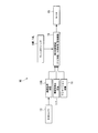
- FIG. 6 is a block diagram of the driving support device.
- the driving assistance apparatus 110 in the present embodiment includes the navigation device 11, the external camera (shooting unit) 13, the blinker switches 14R and 14L, the monitor (display unit) 15, and the side.
- the mirror 16R, 16L, the obstacle detection device 117, the image processing device 118, and the display control device (display unit) 19 are provided.
- the navigation device 11 in the present embodiment executes, for example, processing such as route search and route guidance, and outputs to the display control device 19 navigation image data such as route guidance information to a destination or a transit point along with road data. Do.
- the external camera 13 is configured of, for example, a CCD camera or a CMOS camera capable of imaging in a visible light region, an infrared region, or the like.
- the external camera 13 is disposed below the right side mirror 16R (the side mirror 16R opposite to the driver's seat side (the passenger side)) of the left and right side mirrors 16R, 16L.
- the external camera 13 is disposed below the side mirror 16R on the second side.
- the external camera 13 includes a wide-angle lens, and captures an external image of a predetermined wide-angle area from the right side to the rear of the host vehicle.
- the external camera 13 performs predetermined image processing such as filtering and binarization processing on the image obtained by photographing, generates image data composed of pixels in a two-dimensional array, and outputs the image data to the image processing device 118 .
- the detection target area Z of the external camera 13 is, as shown in FIG. 7, a rear side area Z1 of the vehicle which is a visible range of the right side mirror 16R and a right side mirror 16R adjacent to the rear side area Z1. And a blind spot area Z2 outside the visible range.
- the viewing angle is about 27 ° in the rear side region Z1, and the viewing angle is about 82 ° in the dead angle region Z2, for example.
- the overlapping area Z3 with the vehicle is set to be, for example, about 1 to 2 ° in a viewing angle.
- the blinker switches 14R and 14L are lever switches that signal, for example, the movement of the host vehicle to the first side or the second side to surrounding vehicles. Specifically, the blinker switches 14R and 14L are switched on and off by tilting the blinker lever 21 disposed in front of the steering wheel 20.
- the right blinker switch 14R second blinker switch
- the left blinker switch 14L the first blinker switch
- the left blinker lamp (not shown) blinks.
- the winker switches 14R and 14L are turned off, that is, when the steering wheel 20 returns by a predetermined steering angle or more after a lane change or a left or right turn, or the winker lever 21 is tilted from its own position by its own operation. When it is forcibly returned to the neutral position, the blinking of the blinker lamp ends.
- the obstacle detection device 117 monitors the periphery of the host vehicle and detects whether an obstacle such as an adjacent vehicle, a pedestrian, or a structure approaches the periphery of the host vehicle. Specifically, the obstacle detection device 117 detects the presence of an obstacle by a radar device (not shown) by electromagnetic waves such as millimeter waves, and an imaging device such as a CCD camera (for example, the outside camera 13). If the distance between the vehicle and the obstacle is within a predetermined distance, it is determined that the host vehicle and the obstacle are approaching. Then, the obstacle detection device 117 outputs a warning signal to the display control unit 19 when it is determined that the host vehicle and the obstacle are approaching.
- a radar device not shown
- electromagnetic waves such as millimeter waves
- an imaging device such as a CCD camera
- the image processing device 118 performs enlargement and compression processing on the image data input from the external camera 13, and outputs the image data after image processing to the display control device 19.
- the display control device 19 selectively switches whether to display the navigation image input from the navigation device 11 or the external video image input from the image processing device 118 on the monitor 15. For example, the display control device 19 determines whether the external image is required. The display control device 19 displays the navigation image on the monitor 15 when it is determined that the external video is not necessary, and switches from the navigation image to the external video when it is determined that the external video is necessary.
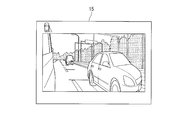
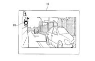
- FIGS. 8A and 8B are diagrams showing a state in which an external video is displayed on the monitor.
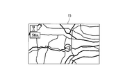
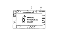
- FIGS. 9A and 9B are diagrams showing a state in which a navigation image (route guidance image) is displayed on a monitor.
- FIG. 5 As shown in FIG. 5, FIG. 6, FIG. 8A and FIG. 8B, when the display control device 19 detects the on operation of the right winker switch 14R among the left and right winker switches 14R and 14L, the driver It is predicted that the driver has the intention to change lanes and turn right, or it is detected that the vehicle is actually performing lane changes and right turn. In this case, it is determined that the external video is required, and the external video (see FIG. 8A) is displayed on the monitor 15.
- the display control device 19 determines that the external video is not necessary when detecting the off operation of the right
- the navigation image (see FIG. 9A) is displayed on the monitor 15.
- the display control device 19 receives an alarm signal from the obstacle detection device 117 described above.
- a warning image is displayed on the monitor 15 to notify the driver of the approach.
- the warning display is superimposed on an image (for example, an external image, a navigation image, etc.) already displayed on the monitor 15.
- an image for example, an external image, a navigation image, etc.
- FIG. 8B when an external video image is displayed on the monitor 15, a first warning image C1 smaller than a second warning image C2 described later is displayed.
- the first warning image C1 is an overlapping area Z3 with the own vehicle in the detection subject area Z of the own vehicle side, specifically, the external camera 13 in the external world image displayed on the monitor 15 (see FIG. 7) is displayed above.
- the second warning image C2 when the external video is not displayed on the monitor 15 (for example, when the navigation image is displayed), the second warning image C2 larger than the first warning image C1 is displayed. Display superimposed on the navigation image.
- the second warning image C2 includes the central portion of the monitor 15 and is set to substantially the entire size of the monitor 15.
- Each of the warning images C1 and C2 described above is configured such that an alerting display is output in a direction in which an obstacle is present with respect to the host vehicle.
- an alerting display is output in a direction in which an obstacle is present with respect to the host vehicle.
- the presence of an obstacle in front of the host vehicle is called out.
- color, brightness, blinking, and the like are changed according to the distance between the host vehicle and the obstacle.
- FIG. 10 is a flowchart for explaining the display control method.
- the external video is not displayed on the monitor 15, it is assumed that the navigation image shown in FIG. 9A is always displayed.
- step S10 it is determined whether the own vehicle and the obstacle are approaching.
- the obstacle detection device 117 detects the presence of an obstacle with a radar device or an imaging device, and determines whether the distance between the host vehicle and the obstacle is within a predetermined distance.
- step S10 When the determination result in step S10 is "NO" (when there is no obstacle or when the distance between the host vehicle and the obstacle is longer than a predetermined distance), it is determined that a warning to the driver is not necessary, The routine of step S10 is repeated. On the other hand, if the determination result in step S10 is "YES” (if there is an obstacle around the host vehicle), it is determined that a warning to the driver is necessary, and the process proceeds to step S20.
- step S20 it is determined whether or not an external video image is displayed on the monitor 15. That is, it is determined whether the right blinker switch 14R is turned on.
- step S20 When the determination result in step S20 is "NO" (when the external video is not displayed on monitor 15), as shown in FIG. 9A, it is determined that the navigation image is displayed on monitor 15, and step Go to S30. Then, in step S30, as shown in FIG. 9B, the second warning image C2 is superimposed and displayed on the monitor 15 on which the navigation image is displayed, and the present routine is ended.
- step S20 determines whether the external video is displayed on the monitor 15 is displayed. If the determination result in step S20 is "YES", as shown in FIG. 8A, it is determined that the external video is displayed on the monitor 15, and the process proceeds to step S40. Then, in step S40, as shown in FIG. 8B, the first warning image C1 is superimposed and displayed on the monitor 15 on which the external video is displayed, and the present routine is ended.
- the first warning image C1 displayed superimposed on the external video image is smaller than the second warning image C2 displayed superimposed on the navigation image.
- the second warning image C2 larger than the first warning image C1 is displayed. Therefore, the driver can surely recognize the presence of the obstacle around the host vehicle.
- the first warning image C1 smaller than the second warning image C2 is displayed. Therefore, the driver can recognize the presence of an obstacle around the host vehicle while checking the external image. Therefore, the warning image can be displayed in an optimal state in accordance with the image already displayed on the monitor 15.
- the second warning image C2 includes the central portion of the screen of the monitor 15 and has a size that covers substantially the entire monitor 15 so that the driver can be reliably notified of the presence of an obstacle around the host vehicle. Can.
- the first warning image C1 is superimposing on the host vehicle displayed in the external video, it is possible that the central portion (effective portion) of the screen of the external video displayed on the monitor 15 is covered by the first warning image C1. It can be suppressed. That is, the first warning image C1 is displayed at a position not disturbing the viewing of the external video. Therefore, the driver can be notified of the presence of an obstacle around the vehicle while securing the visibility of the external image. Therefore, for example, when an obstacle appears in the external image, the first warning image C1 and the obstacle do not overlap on the monitor 15, and the obstacle can be recognized through the monitor 15.
- the external camera 13 is attached to the side mirror 16R on the right side (passenger's seat side).
- the external camera 13 may be attached to the left side mirror 16L. That is, it does not matter if the external camera 13 is attached to at least the side mirror opposite to the driver's seat among the side mirrors 16R and 16L.
- the driver's seat side is the first side (left side), and the passenger seat side is the second side (right side).
- the driver's seat side may be the second side (right side), and the passenger seat side may be the first side (left side).
- the size, the display position on the monitor 15, and the like can be changed as appropriate.
- it may be configured such that all the display of the monitor 15 can be turned off. When another image is displayed or all the display is turned off, a warning image similar to the second warning image C2 may be displayed. That is, it is preferable to adopt a configuration capable of reliably notifying the driver of the presence of an obstacle around the host vehicle by displaying a warning image similar to the second warning image C2 when the external world image is not displayed. .
- the size of the warning image may be made different depending on the image displayed on the monitor 15.
- a warning by sound may be issued.
- the obstacle detection by the obstacle detection device 117 may be performed in any direction with respect to the host vehicle. For example, when obstacle detection is performed on the rear side of the own vehicle, the obstacle can be recognized based on the external image displayed on the monitor 15 and the first warning image C1. Also, when obstacle detection is performed on the front side of the host vehicle, an obstacle on the front side of the host vehicle is recognized on the basis of the first warning image C1 while confirming the rear side of the host vehicle from the outside world image. be able to.
- the first warning image C1 is displayed so as to overlap with the host vehicle displayed in the external image, an obstacle exists on the front side, and on the rear side.
- the first warning image C1 may be displayed closer to the central part or enlarged as compared with the case where the obstacle exists on the rear side. In this case, when an obstacle exists only in the front side, the presence or absence of the obstacle can be recognized more reliably.
- the blinker switches 14R and 14L are not limited to the lever switch, and a touch switch or the like may be used. Furthermore, in the embodiment described above, the configuration has been described in which the external image is switched on / off in response to the switching on / off of the blinker switches 14R and 14L. However, the present invention is not limited to this, and it is also possible to manually switch on / off of the external video.
- the display unit is not limited to the monitor 15 described above, but is integrated with instruments that display various traveling state amounts, or a display device disposed in the vicinity of the instruments, or a fluorocarbon and a window hinders the driver's forward view. It is also possible to constitute by a head-up display or the like which displays various information at the non-location.
- the view angle of the external camera 13 can be appropriately changed in design as long as the rear side area of the host vehicle and a blind area outside the visible range of the side mirror can be photographed.
- driving support device 11 navigation device 13: external camera (photographing unit) 14L: left blinker switch (first blinker switch, second blinker switch) 14R: right blinker switch (first blinker) Switch, second blinker switch) 15 Monitor (display unit) 16 L Left side mirror (side mirror) 16 R Right side mirror 18 Display switching device (display unit) 19 Display control device (display unit) 117 Obstacle detection device 118 ... Image processing device Z1 ... Rear side area Z2 ... Dead angle area C1 ... First warning image (Warning image) C2 ... Second warning image (Warning image)
Landscapes
- Engineering & Computer Science (AREA)
- Radar, Positioning & Navigation (AREA)
- Remote Sensing (AREA)
- Multimedia (AREA)
- Physics & Mathematics (AREA)
- General Physics & Mathematics (AREA)
- Mechanical Engineering (AREA)
- Automation & Control Theory (AREA)
- Signal Processing (AREA)
- Traffic Control Systems (AREA)
- Closed-Circuit Television Systems (AREA)
- Navigation (AREA)
Description
本願は、2012年8月17日に日本国に出願された特願2012-181060号および2012年8月17日に日本国に出願された特願2012-181062号に基づき優先権を主張し、その内容をここに援用する。
この構成によれば、自車両の左右移動(車線移動や右左折等)が完了する前にウィンカスイッチをオフ操作した場合であっても、自車両の左右移動が完了するまでモニタに外界映像を表示し続けることができると考えられる。
また、例えば特許文献2には、車両の後側方領域に障害物を検出した場合に、上述したモニタに警告画像を表示する構成が記載されている。
しかしながら、上述した特許文献1の構成にあっては、ウィンカスイッチのオフ操作から所定時間が経過するまでは外界映像がモニタ上に表示される。そのため、左右のうち、一方側に移動した直後に、他方側に移動する場合等に、ナビゲーション装置の地図画像等を確認することができない。
しかしながら、例えば外界映像が表示されている場合に警告画像を重畳表示すると、外界映像に映る障害物と警告画像とがモニタ上で重なってしまい、モニタを通して障害物を確認することができなくなる虞がある。
(1)本発明の一態様に係る運転支援装置は、車両の車幅方向において、運転席側を第1側、前記第1側と反対側を第2側とした場合、前記車両の前記第2側のサイドミラーに設けられ、前記車両の後側方領域、及び前記後側方領域に隣接し前記第2側のサイドミラーの視認範囲外にある死角領域を撮影可能な撮影部と、前記撮影部が撮影した映像を、前記車両の運転者が視認可能なように表示する表示部と、前記車両の前記第1側又は前記第2側への移動を合図するウィンカスイッチと、を備え、前記表示部は、前記第2側への前記車両の移動を示す前記ウィンカスイッチのオン操作に応じて前記映像を表示するとともに、前記ウィンカスイッチのオフ操作から所定時間経過後に前記映像の表示をオフにし、前記所定時間内に前記車両が前記第1側に移動すると予測した場合に、前記所定時間経過前に前記映像の表示をオフにする。
また、ウィンカスイッチのオフ操作後、所定時間内に車両が第1側又は第2側への移動をすると予測した場合に、定時間経過前に映像の表示をオフにすることで、例えば表示部により表示される画像をナビゲーション画像等に切り替え、速やかに経路案内を確認することができる。
したがって、表示部上に最適な画像を表示して、利便性を向上させることができる。
そして、この場合には、映像の表示をオフにすることで、例えば表示部により表示される映像をナビゲーション画像等に切り替え、速やかに経路案内を確認することができる。
一方、表示部に外界映像が表示されている場合には、表示部に外界映像が表示されていない場合に比べて小さい警告画像が表示される。そのため、運転者は外界映像を確認しながら、車両周囲の障害物の存在を認識することができる。
よって、表示部に表示されている画像に応じて警告画像を最適な状態で表示することができる。
一方、外界映像が表示されている場合は、表示部に表示される外界映像のうち、車両側に寄せて警告画像を表示することで、表示部に表示される外界映像の画面中央部(有効部分)が警告画像に覆われるのを抑制できる。すなわち、警告画像が外界映像を見る際に邪魔にならない位置に表示されるので、外界映像の視認性を確保した上で、車両周囲の障害物の存在を運転者に報せることができる。これにより、例えば外界映像中に障害物が映っている場合等において、警告画像と障害物とが表示部上で重なるのを抑え、表示部を通して障害物を認識することができる。
(運転支援装置)
図1は、運転支援装置の構成図であって、車室内から前方を見た正面図である。図2は、運転支援装置のブロック図である。
道路データは、例えば、交差点及び分岐点等の道路上の所定位置の緯度及び経度からなる座標点であるノードと、各ノード間を結ぶ線であるリンクと、道路形状と、道路種別と、道路の幅員データ、及び制限速度と、を主に備えている。
また、ナビゲーション装置11は、例えば、経路探索や経路案内等の処理を実行し、道路データとともに、例えば目的地や経由地までの経路案内情報等のナビゲーション画像データを表示切替装置18に出力する。
一方、表示切替装置18は、運転者による左側ウィンカスイッチ14Lのオフ操作を検出した場合に、外界映像が必要ない状況であると判断して、所定時間(例えば、2秒程度)経過後にモニタ15の映像をナビゲーション画像に切り替える。
次に、上述した運転支援装置10の動作方法として、モニタ15上での表示切替方法について説明する。図4は、表示切替方法を説明するためのフローチャートである。なお、以下の説明では、モニタ15上に外界映像が表示されていない場合は、ナビゲーション画像が常時表示されているものとする。
一方、ステップS1における判断結果が「YES」の場合(左側ウィンカスイッチ14Lがオン操作された場合)、左車線への車線変更や左折の実行中、または運転者に左車線への車線変更や左折を実行する意志が有ると判断して、ステップS2に進む。
ステップS3における判断結果が「NO」の場合(左側ウィンカスイッチ14Lがオフ操作されていない場合)、左側ウィンカスイッチ14Lが未だオン操作中、すなわち自車両が未だ車線変更中や左折中であり、外界映像が未だ必要であると判断して、ステップS3のルーチンを繰り返す。
一方、ステップS3における判断結果が「YES」の場合(左側ウィンカスイッチ14Lがオフ操作された場合)、ステップS4に進む。
ステップS4における判断結果が「YES」の場合(所定時間が経過した場合)は、外界映像が必要ない状況であると判断して、ステップS5に進み、外界映像の表示をオフにする。この場合、表示切替装置18は、モニタ15に表示される映像を外界映像からナビゲーション画像に切り替える。すなわち、左側ウィンカスイッチ14Lのオフ操作から所定時間経過後には、車線変更や左折が完了しているものと判断して、モニタ15上の映像をナビゲーション画像に戻すようになっている。
以上により、本ルーチンを終了する。
したがって、モニタ15上に最適な画像を表示して、利便性を向上させることができる。
(運転支援装置)
図5は、運転支援装置の構成図であって、車室内から前方を見た正面図である。図6は、運転支援装置のブロック図である。
次に、上述した運転支援装置110の動作方法として、モニタ15上での表示制御方法について説明する。図10は、表示制御方法を説明するためのフローチャートである。なお、以下の説明では、モニタ15上に外界映像が表示されていない場合は、図9Aに示すナビゲーション画像が常時表示されているものとする。
一方、ステップS10における判断結果が「YES」の場合(自車両の周囲に障害物が存在する場合)、運転者への警告が必要であると判断して、ステップS20に進む。
そして、ステップS30では、図9Bに示すように、ナビゲーション画像が表示されたモニタ15上に第2警告画像C2を重畳表示して、本ルーチンを終了する。
そして、ステップS40では、図8Bに示すように、外界映像が表示されたモニタ15上に第1警告画像C1を重畳表示して、本ルーチンを終了する。
よって、モニタ15上に既に表示されている画像に応じて警告画像を最適な状態で表示することができる。
Claims (5)
- 車両の車幅方向において、運転席側を第1側、前記第1側と反対側を第2側とした場合、
前記車両の前記第2側のサイドミラーに設けられ、前記車両の後側方領域、及び前記後側方領域に隣接し前記第2側のサイドミラーの視認範囲外にある死角領域を撮影可能な撮影部と、
前記撮影部が撮影した映像を、前記車両の運転者が視認可能なように表示する表示部と、
前記車両の前記第1側又は前記第2側への移動を合図するウィンカスイッチと、を備え、
前記表示部は、前記第2側への前記車両の移動を示す前記ウィンカスイッチのオン操作に応じて前記映像を表示するとともに、前記ウィンカスイッチのオフ操作から所定時間経過後に前記映像の表示をオフにし、前記所定時間内に前記車両が前記第1側に移動すると予測した場合に、前記所定時間経過前に前記映像の表示をオフにする
ことを特徴とする運転支援装置。 - 前記表示部は、前記第2側への前記車両の移動を示す前記ウィンカスイッチのオフ操作がなされた後、前記所定時間内に前記第1側への前記車両の移動を示す前記ウィンカスイッチのオン操作がなされた場合に、前記所定時間経過前に前記映像の表示をオフにする
ことを特徴とする請求項1に記載の運転支援装置。 - 前記表示部は、前記第2側への前記車両の移動を示す前記ウィンカスイッチのオフ操作がなされた後、ナビゲーション装置からの経路案内情報に基づいて、前記所定時間内に前記車両が前記第1側に移動すると予測した場合に、前記所定時間経過前に前記映像の表示をオフにする
ことを特徴とする請求項1または請求項2に記載の運転支援装置。 - 前記表示部は、前記車両の周囲に障害物が存在する場合に運転者に向けて警告を行う警告画像を表示するとともに、前記映像が表示されている場合は、前記映像が表示されていない場合に比べて小さい前記警告画像を、前記映像に重畳して表示する
ことを特徴とする請求項1から請求項3に記載の運転支援装置。 - 前記映像が表示されていない場合の前記警告画像は、前記表示部における画面中央部を含む位置に表示され、
前記映像が表示されている場合の前記警告画像は、前記表示部に表示される前記映像のうち、前記車両側に寄せて表示される
ことを特徴とする請求項4に記載の運転支援装置。
Priority Applications (4)
| Application Number | Priority Date | Filing Date | Title |
|---|---|---|---|
| JP2014530483A JP5836490B2 (ja) | 2012-08-17 | 2013-05-21 | 運転支援装置 |
| CN201380042527.4A CN104620076B (zh) | 2012-08-17 | 2013-05-21 | 驾驶辅助装置 |
| BR112015002997A BR112015002997A2 (pt) | 2012-08-17 | 2013-05-21 | dispositivo de assistência á condução |
| US14/417,668 US9789819B2 (en) | 2012-08-17 | 2013-05-21 | Driving assistance device |
Applications Claiming Priority (4)
| Application Number | Priority Date | Filing Date | Title |
|---|---|---|---|
| JP2012-181060 | 2012-08-17 | ||
| JP2012181062 | 2012-08-17 | ||
| JP2012-181062 | 2012-08-17 | ||
| JP2012181060 | 2012-08-17 |
Publications (1)
| Publication Number | Publication Date |
|---|---|
| WO2014027489A1 true WO2014027489A1 (ja) | 2014-02-20 |
Family
ID=50685522
Family Applications (1)
| Application Number | Title | Priority Date | Filing Date |
|---|---|---|---|
| PCT/JP2013/064045 Ceased WO2014027489A1 (ja) | 2012-08-17 | 2013-05-21 | 運転支援装置 |
Country Status (5)
| Country | Link |
|---|---|
| US (1) | US9789819B2 (ja) |
| JP (1) | JP5836490B2 (ja) |
| CN (1) | CN104620076B (ja) |
| BR (1) | BR112015002997A2 (ja) |
| WO (1) | WO2014027489A1 (ja) |
Cited By (1)
| Publication number | Priority date | Publication date | Assignee | Title |
|---|---|---|---|---|
| CN107409199A (zh) * | 2015-03-04 | 2017-11-28 | 三菱电机株式会社 | 车辆用显示控制装置及车辆用显示装置 |
Families Citing this family (34)
| Publication number | Priority date | Publication date | Assignee | Title |
|---|---|---|---|---|
| US9164511B1 (en) * | 2013-04-17 | 2015-10-20 | Google Inc. | Use of detected objects for image processing |
| US20160193998A1 (en) * | 2015-01-02 | 2016-07-07 | Atieva, Inc. | Automatically Activated Vehicle Obstacle Viewing System |
| US9428119B2 (en) * | 2015-01-02 | 2016-08-30 | Atieva, Inc. | Location based activation of a vehicle camera system |
| US9305463B1 (en) * | 2015-01-02 | 2016-04-05 | Atieva, Inc. | Automatically activated in-cabin vehicle camera system |
| US9406234B2 (en) * | 2015-01-02 | 2016-08-02 | Atieva, Inc. | Automatically activated blind spot camera system |
| US9428185B2 (en) | 2015-01-02 | 2016-08-30 | Atieva, Inc. | Automatically activated cross traffic camera system |
| JP6224029B2 (ja) * | 2015-05-21 | 2017-11-01 | 富士通テン株式会社 | 画像処理装置および画像処理方法 |
| JP6555348B2 (ja) * | 2015-06-29 | 2019-08-07 | アイシン精機株式会社 | 画像表示制御装置 |
| EP4053821B1 (en) * | 2015-07-28 | 2025-11-12 | NISSAN MOTOR Co., Ltd. | Method for controlling travel control device, and travel control device |
| US9481300B1 (en) * | 2015-11-05 | 2016-11-01 | Christopher A. Lutawan | Proximity alert system |
| US10479373B2 (en) * | 2016-01-06 | 2019-11-19 | GM Global Technology Operations LLC | Determining driver intention at traffic intersections for automotive crash avoidance |
| JP6680593B2 (ja) * | 2016-03-30 | 2020-04-15 | 矢崎総業株式会社 | 運転支援装置 |
| DE102016005284A1 (de) * | 2016-04-30 | 2017-11-02 | Man Truck & Bus Ag | Anordnung für ein Kraftfahrzeug mit einer Kamera und einem Display |
| JP6390035B2 (ja) * | 2016-05-23 | 2018-09-19 | 本田技研工業株式会社 | 車両制御システム、車両制御方法、および車両制御プログラム |
| JP6712906B2 (ja) * | 2016-05-31 | 2020-06-24 | 株式会社小松製作所 | 作業機械の管理装置、作業機械、及び作業機械の管理システム |
| JP6504145B2 (ja) * | 2016-11-24 | 2019-04-24 | 株式会社Jvcケンウッド | 車両用記録装置 |
| CN106740476A (zh) * | 2016-12-28 | 2017-05-31 | 深圳市赛格导航科技股份有限公司 | 一种汽车驾驶环境监控方法、装置及汽车 |
| JP7122517B2 (ja) * | 2017-04-27 | 2022-08-22 | パナソニックIpマネジメント株式会社 | 車載表示装置 |
| US10421399B2 (en) * | 2017-05-26 | 2019-09-24 | GM Global Technology Operations LLC | Driver alert systems and methods based on the presence of cyclists |
| US10427596B2 (en) * | 2017-07-27 | 2019-10-01 | Alexa Lea Haushalter | Vehicle directional indicator for autonomous and non-autonomous vehicles |
| JP6804416B2 (ja) * | 2017-09-25 | 2020-12-23 | 矢崎総業株式会社 | 監視システム |
| JP6939368B2 (ja) * | 2017-10-04 | 2021-09-22 | トヨタ自動車株式会社 | 画像表示装置 |
| EP3489087B1 (en) * | 2017-11-24 | 2021-05-05 | Ficomirrors, S.A.U. | Vehicle imaging system |
| DE112018006931T5 (de) * | 2018-02-27 | 2020-10-08 | Mitsubishi Electric Corporation | Fahrzeugbildschirmsteuerungssystem und bildschirmsteuerungsverfahren |
| CN108482242A (zh) * | 2018-03-09 | 2018-09-04 | 深圳市歌美迪电子技术发展有限公司 | 车辆转向控制方法、装置、车载控制器和车辆 |
| CN108482247A (zh) * | 2018-03-27 | 2018-09-04 | 京东方科技集团股份有限公司 | 一种车辆及其辅助驾驶系统和辅助驾驶方法 |
| CN111284407B (zh) * | 2018-12-06 | 2022-12-02 | 沈阳美行科技股份有限公司 | 一种用于辅助转向的显示方法及装置、装置及相关设备 |
| JP7187291B2 (ja) * | 2018-12-14 | 2022-12-12 | 株式会社小糸製作所 | 赤外線カメラシステム及び車両 |
| US12036917B2 (en) * | 2019-01-12 | 2024-07-16 | Zmp Inc. | Autonomous vehicle, delivery system, and program |
| WO2020194715A1 (ja) | 2019-03-28 | 2020-10-01 | 本田技研工業株式会社 | 鞍乗り型車両 |
| JP6921160B2 (ja) * | 2019-10-29 | 2021-08-18 | 三菱電機株式会社 | 車両の後側方監視装置 |
| CN112349142B (zh) * | 2020-10-29 | 2022-06-17 | 深圳市元征科技股份有限公司 | 一种车辆追尾预警方法及其相关设备 |
| EP4105083B1 (en) | 2021-06-18 | 2023-08-30 | Volvo Car Corporation | Monitoring system for a vehicle |
| CN119329415B (zh) * | 2024-11-18 | 2026-04-17 | 东风汽车集团股份有限公司 | 360影像启闭方法、装置、设备及存储介质 |
Citations (4)
| Publication number | Priority date | Publication date | Assignee | Title |
|---|---|---|---|---|
| JP2001260776A (ja) * | 2000-03-22 | 2001-09-26 | Mazda Motor Corp | 車両用障害物警報装置 |
| JP2005170286A (ja) * | 2003-12-12 | 2005-06-30 | Ichikoh Ind Ltd | 車両用映像表示装置 |
| JP2007112360A (ja) * | 2005-10-21 | 2007-05-10 | Aisin Aw Co Ltd | 運転支援装置 |
| WO2010137684A1 (ja) * | 2009-05-29 | 2010-12-02 | 富士通テン株式会社 | 画像生成装置及び画像表示システム |
Family Cites Families (16)
| Publication number | Priority date | Publication date | Assignee | Title |
|---|---|---|---|---|
| JP3613111B2 (ja) | 2000-01-20 | 2005-01-26 | 日本電気株式会社 | レーザ加工用セラミックグリーンシートおよびその加工方法、該シートを用いた焼結体、積層デバイス |
| WO2001064481A2 (en) * | 2000-03-02 | 2001-09-07 | Donnelly Corporation | Video mirror systems incorporating an accessory module |
| US8287374B2 (en) * | 2000-07-07 | 2012-10-16 | Pryor Timothy R | Reconfigurable control displays for games, toys, and other applications |
| JP3645196B2 (ja) * | 2001-02-09 | 2005-05-11 | 松下電器産業株式会社 | 画像合成装置 |
| US8083588B2 (en) * | 2003-09-04 | 2011-12-27 | Pryor Timothy R | Reconfigurable surface based video games |
| US20050134982A1 (en) * | 2003-12-23 | 2005-06-23 | Bob Stonecypher | Blind spot curved mirror |
| JP2007223338A (ja) | 2004-07-12 | 2007-09-06 | Sharp Corp | 表示システム、移動体、表示方法、表示プログラムおよびその記録媒体 |
| JP2006072830A (ja) * | 2004-09-03 | 2006-03-16 | Aisin Aw Co Ltd | 運転支援システム及び運転支援モジュール |
| WO2007021263A1 (en) * | 2005-08-10 | 2007-02-22 | Autoliv Asp, Inc. | Improved steering apparatus |
| JP5117003B2 (ja) | 2006-07-11 | 2013-01-09 | 本田技研工業株式会社 | 運転支援装置 |
| WO2010080610A1 (en) | 2008-12-19 | 2010-07-15 | Delphi Technologies, Inc. | Electronic side view display system |
| JP5426900B2 (ja) | 2009-02-26 | 2014-02-26 | アルパイン株式会社 | 車載システム |
| TW201100280A (en) * | 2009-06-19 | 2011-01-01 | Automotive Res & Testing Ct | Collision warning system for vehicle |
| JP2011003117A (ja) | 2009-06-22 | 2011-01-06 | Central Motor Co Ltd | 後方視認支援システム |
| US20110133957A1 (en) * | 2009-12-03 | 2011-06-09 | Delphi Technologies, Inc. | Vehicle parking locator system and method using connected vehicles |
| US9586525B2 (en) * | 2011-11-28 | 2017-03-07 | Robert Bosch Gmbh | Camera-assisted blind spot detection |
-
2013
- 2013-05-21 BR BR112015002997A patent/BR112015002997A2/pt not_active Application Discontinuation
- 2013-05-21 WO PCT/JP2013/064045 patent/WO2014027489A1/ja not_active Ceased
- 2013-05-21 US US14/417,668 patent/US9789819B2/en active Active
- 2013-05-21 CN CN201380042527.4A patent/CN104620076B/zh active Active
- 2013-05-21 JP JP2014530483A patent/JP5836490B2/ja active Active
Patent Citations (4)
| Publication number | Priority date | Publication date | Assignee | Title |
|---|---|---|---|---|
| JP2001260776A (ja) * | 2000-03-22 | 2001-09-26 | Mazda Motor Corp | 車両用障害物警報装置 |
| JP2005170286A (ja) * | 2003-12-12 | 2005-06-30 | Ichikoh Ind Ltd | 車両用映像表示装置 |
| JP2007112360A (ja) * | 2005-10-21 | 2007-05-10 | Aisin Aw Co Ltd | 運転支援装置 |
| WO2010137684A1 (ja) * | 2009-05-29 | 2010-12-02 | 富士通テン株式会社 | 画像生成装置及び画像表示システム |
Cited By (1)
| Publication number | Priority date | Publication date | Assignee | Title |
|---|---|---|---|---|
| CN107409199A (zh) * | 2015-03-04 | 2017-11-28 | 三菱电机株式会社 | 车辆用显示控制装置及车辆用显示装置 |
Also Published As
| Publication number | Publication date |
|---|---|
| JP5836490B2 (ja) | 2015-12-24 |
| BR112015002997A2 (pt) | 2017-07-04 |
| JPWO2014027489A1 (ja) | 2016-07-25 |
| CN104620076A (zh) | 2015-05-13 |
| US20150203033A1 (en) | 2015-07-23 |
| US9789819B2 (en) | 2017-10-17 |
| CN104620076B (zh) | 2017-05-17 |
Similar Documents
| Publication | Publication Date | Title |
|---|---|---|
| JP5836490B2 (ja) | 運転支援装置 | |
| JP4855158B2 (ja) | 運転支援装置 | |
| JP5117003B2 (ja) | 運転支援装置 | |
| JP4134939B2 (ja) | 車両周辺表示制御装置 | |
| US8461976B2 (en) | On-vehicle device and recognition support system | |
| JP6511015B2 (ja) | 車両モニタシステム | |
| JP6014433B2 (ja) | 画像処理装置、画像処理方法、及び、画像処理システム | |
| CN106660485B (zh) | 用于辅助车辆驾驶的后视系统 | |
| JP2013156927A (ja) | 注意喚起装置およびプログラム | |
| JP2013161440A (ja) | 車両周辺監視装置 | |
| JP6932631B2 (ja) | 画像表示装置及び運転支援システム | |
| JP5885619B2 (ja) | 運転支援装置 | |
| JP2020037357A (ja) | 車両用周辺表示装置 | |
| CN113060156B (zh) | 车辆周围监视装置、车辆、车辆周围监视方法和程序 | |
| JP4218453B2 (ja) | 車両用前方視界支援装置 | |
| US20250316094A1 (en) | Image processing device, mobile object, image processing method, and storage medium | |
| JP2004051063A (ja) | 車両周辺視認装置 | |
| JP2017194784A (ja) | 車両用運転支援装置及び車両用運転支援プログラム | |
| JP6127391B2 (ja) | 車両周辺視認装置 | |
| US20240123905A1 (en) | Display system, vehicle, control method, and storage medium | |
| JP4081548B2 (ja) | 運転支援システム | |
| JP2007180622A (ja) | 車両周囲監視装置 | |
| JP2013146029A (ja) | 車両周辺監視装置 | |
| JP2006268224A (ja) | 車両用運転支援装置 | |
| JP2024102638A (ja) | 画像処理システム、移動体、画像処理方法、及びコンピュータプログラム |
Legal Events
| Date | Code | Title | Description |
|---|---|---|---|
| ENP | Entry into the national phase |
Ref document number: 2014530483 Country of ref document: JP Kind code of ref document: A |
|
| 121 | Ep: the epo has been informed by wipo that ep was designated in this application |
Ref document number: 13879305 Country of ref document: EP Kind code of ref document: A1 |
|
| WWE | Wipo information: entry into national phase |
Ref document number: 14417668 Country of ref document: US |
|
| NENP | Non-entry into the national phase |
Ref country code: DE |
|
| 122 | Ep: pct application non-entry in european phase |
Ref document number: 13879305 Country of ref document: EP Kind code of ref document: A1 |
|
| REG | Reference to national code |
Ref country code: BR Ref legal event code: B01A Ref document number: 112015002997 Country of ref document: BR |
|
| ENP | Entry into the national phase |
Ref document number: 112015002997 Country of ref document: BR Kind code of ref document: A2 Effective date: 20150211 |