WO2014017356A1 - 自動変速機の制御装置及び制御方法 - Google Patents
自動変速機の制御装置及び制御方法 Download PDFInfo
- Publication number
- WO2014017356A1 WO2014017356A1 PCT/JP2013/069413 JP2013069413W WO2014017356A1 WO 2014017356 A1 WO2014017356 A1 WO 2014017356A1 JP 2013069413 W JP2013069413 W JP 2013069413W WO 2014017356 A1 WO2014017356 A1 WO 2014017356A1
- Authority
- WO
- WIPO (PCT)
- Prior art keywords
- friction element
- automatic transmission
- hydraulic pressure
- state
- power source
- Prior art date
- Legal status (The legal status is an assumption and is not a legal conclusion. Google has not performed a legal analysis and makes no representation as to the accuracy of the status listed.)
- Ceased
Links
Images


Classifications
-
- B—PERFORMING OPERATIONS; TRANSPORTING
- B60—VEHICLES IN GENERAL
- B60W—CONJOINT CONTROL OF VEHICLE SUB-UNITS OF DIFFERENT TYPE OR DIFFERENT FUNCTION; CONTROL SYSTEMS SPECIALLY ADAPTED FOR HYBRID VEHICLES; ROAD VEHICLE DRIVE CONTROL SYSTEMS FOR PURPOSES NOT RELATED TO THE CONTROL OF A PARTICULAR SUB-UNIT
- B60W10/00—Conjoint control of vehicle sub-units of different type or different function
- B60W10/04—Conjoint control of vehicle sub-units of different type or different function including control of propulsion units
- B60W10/06—Conjoint control of vehicle sub-units of different type or different function including control of propulsion units including control of combustion engines
-
- F—MECHANICAL ENGINEERING; LIGHTING; HEATING; WEAPONS; BLASTING
- F16—ENGINEERING ELEMENTS AND UNITS; GENERAL MEASURES FOR PRODUCING AND MAINTAINING EFFECTIVE FUNCTIONING OF MACHINES OR INSTALLATIONS; THERMAL INSULATION IN GENERAL
- F16H—GEARING
- F16H61/00—Control functions within control units of change-speed- or reversing-gearings for conveying rotary motion ; Control of exclusively fluid gearing, friction gearing, gearings with endless flexible members or other particular types of gearing
- F16H61/04—Smoothing ratio shift
-
- B—PERFORMING OPERATIONS; TRANSPORTING
- B60—VEHICLES IN GENERAL
- B60W—CONJOINT CONTROL OF VEHICLE SUB-UNITS OF DIFFERENT TYPE OR DIFFERENT FUNCTION; CONTROL SYSTEMS SPECIALLY ADAPTED FOR HYBRID VEHICLES; ROAD VEHICLE DRIVE CONTROL SYSTEMS FOR PURPOSES NOT RELATED TO THE CONTROL OF A PARTICULAR SUB-UNIT
- B60W10/00—Conjoint control of vehicle sub-units of different type or different function
- B60W10/04—Conjoint control of vehicle sub-units of different type or different function including control of propulsion units
-
- B—PERFORMING OPERATIONS; TRANSPORTING
- B60—VEHICLES IN GENERAL
- B60W—CONJOINT CONTROL OF VEHICLE SUB-UNITS OF DIFFERENT TYPE OR DIFFERENT FUNCTION; CONTROL SYSTEMS SPECIALLY ADAPTED FOR HYBRID VEHICLES; ROAD VEHICLE DRIVE CONTROL SYSTEMS FOR PURPOSES NOT RELATED TO THE CONTROL OF A PARTICULAR SUB-UNIT
- B60W10/00—Conjoint control of vehicle sub-units of different type or different function
- B60W10/10—Conjoint control of vehicle sub-units of different type or different function including control of change-speed gearings
-
- F—MECHANICAL ENGINEERING; LIGHTING; HEATING; WEAPONS; BLASTING
- F16—ENGINEERING ELEMENTS AND UNITS; GENERAL MEASURES FOR PRODUCING AND MAINTAINING EFFECTIVE FUNCTIONING OF MACHINES OR INSTALLATIONS; THERMAL INSULATION IN GENERAL
- F16D—COUPLINGS FOR TRANSMITTING ROTATION; CLUTCHES; BRAKES
- F16D48/00—External control of clutches
- F16D48/02—Control by fluid pressure
-
- F—MECHANICAL ENGINEERING; LIGHTING; HEATING; WEAPONS; BLASTING
- F16—ENGINEERING ELEMENTS AND UNITS; GENERAL MEASURES FOR PRODUCING AND MAINTAINING EFFECTIVE FUNCTIONING OF MACHINES OR INSTALLATIONS; THERMAL INSULATION IN GENERAL
- F16H—GEARING
- F16H61/00—Control functions within control units of change-speed- or reversing-gearings for conveying rotary motion ; Control of exclusively fluid gearing, friction gearing, gearings with endless flexible members or other particular types of gearing
- F16H61/0021—Generation or control of line pressure
- F16H61/0025—Supply of control fluid; Pumps therefor
-
- F—MECHANICAL ENGINEERING; LIGHTING; HEATING; WEAPONS; BLASTING
- F16—ENGINEERING ELEMENTS AND UNITS; GENERAL MEASURES FOR PRODUCING AND MAINTAINING EFFECTIVE FUNCTIONING OF MACHINES OR INSTALLATIONS; THERMAL INSULATION IN GENERAL
- F16H—GEARING
- F16H61/00—Control functions within control units of change-speed- or reversing-gearings for conveying rotary motion ; Control of exclusively fluid gearing, friction gearing, gearings with endless flexible members or other particular types of gearing
- F16H61/02—Control functions within control units of change-speed- or reversing-gearings for conveying rotary motion ; Control of exclusively fluid gearing, friction gearing, gearings with endless flexible members or other particular types of gearing characterised by the signals used
- F16H61/0202—Control functions within control units of change-speed- or reversing-gearings for conveying rotary motion ; Control of exclusively fluid gearing, friction gearing, gearings with endless flexible members or other particular types of gearing characterised by the signals used the signals being electric
- F16H61/0204—Control functions within control units of change-speed- or reversing-gearings for conveying rotary motion ; Control of exclusively fluid gearing, friction gearing, gearings with endless flexible members or other particular types of gearing characterised by the signals used the signals being electric for gearshift control, e.g. control functions for performing shifting or generation of shift signal
-
- F—MECHANICAL ENGINEERING; LIGHTING; HEATING; WEAPONS; BLASTING
- F16—ENGINEERING ELEMENTS AND UNITS; GENERAL MEASURES FOR PRODUCING AND MAINTAINING EFFECTIVE FUNCTIONING OF MACHINES OR INSTALLATIONS; THERMAL INSULATION IN GENERAL
- F16H—GEARING
- F16H61/00—Control functions within control units of change-speed- or reversing-gearings for conveying rotary motion ; Control of exclusively fluid gearing, friction gearing, gearings with endless flexible members or other particular types of gearing
- F16H61/14—Control of torque converter lock-up clutches
-
- F—MECHANICAL ENGINEERING; LIGHTING; HEATING; WEAPONS; BLASTING
- F16—ENGINEERING ELEMENTS AND UNITS; GENERAL MEASURES FOR PRODUCING AND MAINTAINING EFFECTIVE FUNCTIONING OF MACHINES OR INSTALLATIONS; THERMAL INSULATION IN GENERAL
- F16H—GEARING
- F16H61/00—Control functions within control units of change-speed- or reversing-gearings for conveying rotary motion ; Control of exclusively fluid gearing, friction gearing, gearings with endless flexible members or other particular types of gearing
- F16H61/70—Control functions within control units of change-speed- or reversing-gearings for conveying rotary motion ; Control of exclusively fluid gearing, friction gearing, gearings with endless flexible members or other particular types of gearing specially adapted for change-speed gearing in group arrangement, i.e. with separate change-speed gear trains arranged in series, e.g. range or overdrive-type gearing arrangements
- F16H61/702—Control functions within control units of change-speed- or reversing-gearings for conveying rotary motion ; Control of exclusively fluid gearing, friction gearing, gearings with endless flexible members or other particular types of gearing specially adapted for change-speed gearing in group arrangement, i.e. with separate change-speed gear trains arranged in series, e.g. range or overdrive-type gearing arrangements using electric or electrohydraulic control means
-
- B—PERFORMING OPERATIONS; TRANSPORTING
- B60—VEHICLES IN GENERAL
- B60W—CONJOINT CONTROL OF VEHICLE SUB-UNITS OF DIFFERENT TYPE OR DIFFERENT FUNCTION; CONTROL SYSTEMS SPECIALLY ADAPTED FOR HYBRID VEHICLES; ROAD VEHICLE DRIVE CONTROL SYSTEMS FOR PURPOSES NOT RELATED TO THE CONTROL OF A PARTICULAR SUB-UNIT
- B60W30/00—Purposes of road vehicle drive control systems not related to the control of a particular sub-unit, e.g. of systems using conjoint control of vehicle sub-units
- B60W30/18—Propelling the vehicle
- B60W30/18009—Propelling the vehicle related to particular drive situations
- B60W30/18072—Coasting
- B60W2030/1809—Without torque flow between driveshaft and engine, e.g. with clutch disengaged or transmission in neutral
-
- B—PERFORMING OPERATIONS; TRANSPORTING
- B60—VEHICLES IN GENERAL
- B60Y—INDEXING SCHEME RELATING TO ASPECTS CROSS-CUTTING VEHICLE TECHNOLOGY
- B60Y2300/00—Purposes or special features of road vehicle drive control systems
- B60Y2300/18—Propelling the vehicle
- B60Y2300/18008—Propelling the vehicle related to particular drive situations
- B60Y2300/18066—Coasting
- B60Y2300/18083—Coasting without torque flow between driveshaft and engine, e.g. with clutch disengaged or transmission in neutral
-
- B—PERFORMING OPERATIONS; TRANSPORTING
- B60—VEHICLES IN GENERAL
- B60Y—INDEXING SCHEME RELATING TO ASPECTS CROSS-CUTTING VEHICLE TECHNOLOGY
- B60Y2300/00—Purposes or special features of road vehicle drive control systems
- B60Y2300/18—Propelling the vehicle
- B60Y2300/192—Power-up or power-down of the driveline, e.g. start up of a cold engine
-
- B—PERFORMING OPERATIONS; TRANSPORTING
- B60—VEHICLES IN GENERAL
- B60Y—INDEXING SCHEME RELATING TO ASPECTS CROSS-CUTTING VEHICLE TECHNOLOGY
- B60Y2400/00—Special features of vehicle units
- B60Y2400/70—Gearings
- B60Y2400/72—Continous variable transmissions [CVT]
-
- F—MECHANICAL ENGINEERING; LIGHTING; HEATING; WEAPONS; BLASTING
- F16—ENGINEERING ELEMENTS AND UNITS; GENERAL MEASURES FOR PRODUCING AND MAINTAINING EFFECTIVE FUNCTIONING OF MACHINES OR INSTALLATIONS; THERMAL INSULATION IN GENERAL
- F16H—GEARING
- F16H59/00—Control inputs to control units of change-speed- or reversing-gearings for conveying rotary motion
- F16H59/14—Inputs being a function of torque or torque demand
- F16H59/18—Inputs being a function of torque or torque demand dependent on the position of the accelerator pedal
- F16H2059/186—Coasting
-
- F—MECHANICAL ENGINEERING; LIGHTING; HEATING; WEAPONS; BLASTING
- F16—ENGINEERING ELEMENTS AND UNITS; GENERAL MEASURES FOR PRODUCING AND MAINTAINING EFFECTIVE FUNCTIONING OF MACHINES OR INSTALLATIONS; THERMAL INSULATION IN GENERAL
- F16H—GEARING
- F16H2312/00—Driving activities
- F16H2312/14—Going to, or coming from standby operation, e.g. for engine start-stop operation at traffic lights
-
- Y—GENERAL TAGGING OF NEW TECHNOLOGICAL DEVELOPMENTS; GENERAL TAGGING OF CROSS-SECTIONAL TECHNOLOGIES SPANNING OVER SEVERAL SECTIONS OF THE IPC; TECHNICAL SUBJECTS COVERED BY FORMER USPC CROSS-REFERENCE ART COLLECTIONS [XRACs] AND DIGESTS
- Y02—TECHNOLOGIES OR APPLICATIONS FOR MITIGATION OR ADAPTATION AGAINST CLIMATE CHANGE
- Y02T—CLIMATE CHANGE MITIGATION TECHNOLOGIES RELATED TO TRANSPORTATION
- Y02T10/00—Road transport of goods or passengers
- Y02T10/60—Other road transportation technologies with climate change mitigation effect
Definitions
- the present invention relates to a control device and control method of an automatic transmission in a vehicle that performs stopping and restarting of a driving power source.
- An idle stop technology is widely used to improve fuel efficiency by stopping an engine that is a driving power source when the vehicle is stopped.
- so-called coast stop control in which the engine is stopped before the vehicle stops, such as at the time of deceleration, as well as when the vehicle is stopped, has been put to practical use.
- engagement of a friction element such as a clutch is controlled by hydraulic pressure.
- switching of the friction element may be performed in preparation for reacceleration and re-start.
- the oil pump driven by the engine can not generate the hydraulic pressure, so the supply of the hydraulic pressure for switching the friction element may be reduced.
- JP2006-170295A automatically stops the engine while the vehicle is traveling to place the automatic transmission in a neutral state, and after the engine stops, operates the electric oil pump to generate a friction element. It is disclosed to supply hydraulic pressure, that is, to initiate so-called precharging.
- the friction element in the engagement state may slip, and thus, the torque may be lost due to slip or the engagement may occur.
- the shock may change the longitudinal acceleration of the vehicle, which may cause the driver to feel uncomfortable.
- the present invention has been made in view of such problems, and it is an object of the present invention to provide a control device of an automatic transmission capable of suppressing a slip of a friction element and reducing a sense of discomfort given to a driver in coast stop control. I assume.
- a transmission source driving a vehicle, an oil pressure source driven by the driving source to generate an oil pressure, and a transmission gear ratio according to the engagement state of the first friction element and the second friction element
- a control unit for transmitting the driving force of the driving force source to the driving wheels, and a control unit for controlling the operation of the driving force source, the hydraulic pressure source, and the transmission mechanism.
- the control unit outputs a stop command to the drive power source to stop the drive power source when the vehicle is in a traveling state, the first friction element is in the engaged state, and the second friction element is in the release state.
- a friction element control unit for controlling an engagement state of the first friction element and the second friction element, the friction element control unit stopping the driving force source by the coast stop control unit.
- the second friction element is started to be supplied with hydraulic pressure after the command is issued until the rotation of the hydraulic pressure source is stopped.
- a driving force source for driving a vehicle an oil pressure source driven by the driving force source to generate an oil pressure, and a fastening state of a first friction element and a second friction element
- the automatic transmission in a vehicle includes: an automatic transmission that changes the transmission gear ratio and transmits the driving force of the driving force source to the driving wheels; and a control unit that controls the operation of the driving force source, the hydraulic pressure source, and the transmission mechanism.
- the control method of The control method is such that when the vehicle is in a traveling state, the first friction element is in the engaged state, and the second friction element is in the release state, the drive power source stop command is output to stop the drive power source. Then, the supply of oil pressure to the second friction element is started while the rotation of the oil pressure source is stopped.
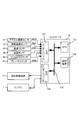
- FIG. 1 is a schematic configuration diagram of a vehicle equipped with a continuously variable transmission according to an embodiment of the present invention.
- FIG. 2 is an explanatory view showing an example of the configuration of the transmission controller according to the embodiment of the present invention.
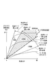
- FIG. 3 is an explanatory view showing an example of a shift map according to the embodiment of the present invention.
- Drawing 4 is an explanatory view at the time of coast stop control of a comparative example
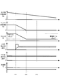
- Drawing 5 is an explanatory view at the time of coast stop control of an embodiment of the present invention.
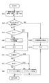
- FIG. 6 is a flowchart of coast stop control according to the embodiment of this invention.
- FIG. 1 is a schematic block diagram of a vehicle equipped with a continuously variable transmission according to an embodiment of the present invention.
- the vehicle is equipped with an engine 1 as a power source.
- the output rotation of the engine 1 is performed via a torque converter 2 with a lockup clutch, a first gear train 3, a continuously variable transmission (hereinafter simply referred to as "transmission 4"), a second gear train 5, and a final reduction gear 6. And is transmitted to the drive wheel 7.
- the second gear train 5 is provided with a parking mechanism 8 which mechanically locks the output shaft of the transmission 4 in a non-rotatable manner during parking.
- the vehicle is provided with a mechanical oil pump 10m, which receives rotation of the engine 1 and is driven using a portion of the power of the engine 1, and an electric oil pump 10e, which is driven by receiving power supply from the battery 13. It is done.
- the transmission 4 controls the hydraulic control circuit 11, which controls the hydraulic pressure supplied from at least one of the mechanical oil pump 10m and the electric oil pump 10e, and supplies the hydraulic control circuit 11, the engine 1 and the hydraulic control circuit 11.
- a controller 12 is provided.
- the transmission 4 includes a continuously variable transmission mechanism (hereinafter, referred to as “variator 20”) and an auxiliary transmission mechanism 30 provided in series with the variator 20.
- the "in series” means that the variator 20 and the auxiliary transmission mechanism 30 are provided in series in the same power transmission path.
- the auxiliary transmission mechanism 30 may be directly connected to the output shaft of the variator 20 as in this example, or may be connected via another transmission or power transmission mechanism (for example, a gear train).
- the variator 20 is a belt-type continuously variable transmission mechanism including a primary pulley 21, a secondary pulley 22, and a belt (V-belt) 23 wound around the pulleys 21 and 22.
- the pulleys 21 and 22 each have a fixed conical plate, a movable conical plate disposed with the sheave surface facing the fixed conical plate and forming a V-groove between the fixed conical plate, and a back surface of the movable conical plate And hydraulic cylinders 23a and 23b for axially displacing the movable conical plate.
- the auxiliary transmission mechanism 30 is a transmission mechanism having two forward gears and one reverse gear.
- the auxiliary transmission mechanism 30 is connected to a Ravigneaux type planetary gear mechanism 31 connecting carriers of two planet gears, and a plurality of rotating elements constituting the Ravigneaux type planetary gear mechanism 31, and a plurality of frictions that change the linkage state thereof.
- An element (Low brake 32, High clutch 33, Rev brake 34) is provided.
- the gear position of the auxiliary transmission mechanism 30 becomes the first gear. If the High clutch 33 is engaged and the Low brake 32 and the Rev brake 34 are released, the gear position of the auxiliary transmission mechanism 30 becomes the second gear whose gear ratio is smaller than the first gear. If the Rev brake 34 is engaged and the Low brake 32 and the High clutch 33 are released, the gear position of the auxiliary transmission mechanism 30 is in reverse.
- the gear position of the auxiliary transmission mechanism 30 is the first speed, it is expressed as "the transmission 4 is in the low speed mode", and when it is the second speed, it is expressed as "the transmission 4 is in the high speed mode”. .
- the controller 12 is a control unit that controls the engine 1 and the transmission 4 in an integrated manner, and as shown in FIG. 2, the CPU 121, a storage device 122 composed of a RAM and ROM, an input interface 123, and an output interface 124. , And a bus 125 interconnecting them.
- the storage device 122 stores a control program of the engine 1, a shift control program of the transmission 4, and a shift map (FIG. 3) used in the shift control program.
- the CPU 121 reads out and executes the transmission control program stored in the storage device 122, performs various arithmetic processing on various signals input through the input interface 123, and generates a fuel injection signal, an ignition timing signal, and a throttle. An opening degree signal and a transmission control signal are generated, and the generated transmission control signal is output to the hydraulic control circuit 11 via the output interface 124.
- Various values used by the CPU 121 in the arithmetic processing, and the arithmetic result thereof are stored in the storage device 122 as appropriate.
- the hydraulic control circuit 11 is composed of a plurality of flow paths and a plurality of hydraulic control valves.
- the hydraulic control circuit 11 controls a plurality of hydraulic control valves based on the shift control signal from the controller 12 to switch the supply path of the hydraulic pressure, and the necessary hydraulic pressure is generated from the hydraulic pressure generated by the mechanical oil pump 10m or the electric oil pump 10e. It prepares and supplies this to each part of the transmission 4. As a result, the transmission ratio v Ratio of the variator 20 and the gear position of the auxiliary transmission mechanism 30 are changed, and the transmission 4 is shifted.
- FIG. 3 shows an example of a shift map stored in the storage device 122 of the controller 12 of this embodiment.
- the operating point of the transmission 4 is determined based on the vehicle speed VSP and the primary rotational speed Npri.
- the slope of the line connecting the operating point of the transmission 4 and the zero point of the lower left corner of the shift map is the transmission ratio of the transmission 4 (the overall transmission ratio obtained by multiplying the transmission ratio v Ratio of the variator 20 by the transmission ratio sub Ratio of the auxiliary transmission mechanism 30 Hereinafter, it is referred to as “through gear ratio Ratio”.
- a shift line is set for each accelerator opening APO, and the shift of the transmission 4 is performed according to a shift line selected according to the accelerator opening APO.
- a shift line selected according to the accelerator opening APO.
- all load lines shift lines when the accelerator opening APO is 8/8
- partial lines shift lines when the accelerator opening APO is 4/8
- a coast line acceleration opening Only the shift line
- the transmission 4 can obtain the low speed mode Lowest line obtained by maximizing the transmission ratio vRatio of the variator 20 and the low speed mode highest line obtained by minimizing the transmission ratio vRatio of the variator 20 It is possible to shift between gears. At this time, the operating point of the transmission 4 moves in the A area and the B area.
- the transmission 4 when the transmission 4 is in the high speed mode, the transmission 4 can obtain the high speed mode Lowest line obtained by maximizing the transmission ratio v Ratio of the variator 20 and the high speed mode highest obtained by minimizing the transmission ratio v Ratio of the variator 20. You can shift between the lines. At this time, the operating point of the transmission 4 moves in the B area and the C area.
- the controller 12 controls the transmission ratio of the variator 20 and the auxiliary transmission mechanism 30 by setting the through transmission ratio Ratio corresponding to the vehicle speed VSP and the accelerator opening APO (the driving state of the vehicle) with reference to the transmission map.
- the controller 12 stops the rotation of the engine 1 while the vehicle is traveling, in addition to the idle stop control that stops the rotation of the engine 1 while the vehicle is stopped, in order to suppress the fuel consumption. Perform coast stop control.
- the coast stop control is control for automatically stopping the engine 1 to suppress the fuel consumption while the vehicle is traveling in the low vehicle speed region.
- the coast stop control is common to the fuel cut control performed when the accelerator is off and to stop the fuel supply to the engine 1, but the normal fuel cut control is performed at relatively high speed traveling and the engine brake While the lockup clutch of the torque converter 2 is engaged in order to secure it, the coast stop control is executed at a relatively low speed traveling just before the vehicle stops, and the engine 1 is rotated with the lockup clutch released. It differs in the point to make it stop.
- the controller 12 first determines, for example, the following conditions (a) to (f).
- the controller 12 determines that the coast stop condition is satisfied when the conditions (a) to (f) are satisfied.
- the coast stop condition is satisfied, the supply of fuel to the engine 1 is stopped and the rotation of the engine 1 is stopped.
- FIG. 4 is an explanatory view at the time of coast stop control of a comparative example in the embodiment of the present invention, and shows problems of the prior art.
- the output shaft rotational speed No of the transmission 4 from the top, the output shaft rotational speed No of the transmission 4, the engine rotational speed Ne, the line pressure PL, the indicated pressure (solid line) and the actual pressure (dotted line) of the low brake 32, the indicated pressure (solid line) of the high clutch 33 And actual pressure (dotted line) and acceleration of the vehicle.
- the primary hydraulic pressure Ppri is a value that is adjusted by the hydraulic control circuit 11 and the hydraulic pressure supplied to each part of the transmission 4 is exemplified.
- a vehicle speed VSP can be obtained by multiplying the output rotational speed No by the reduction ratio of the final reduction gear, the wheel diameter of the drive wheel 7 and the like.
- the command pressure of the High clutch 33 and the actual pressure are described with a slight difference, but this is merely a disagreement for the sake of explanation, and in practice the command pressure and the actual pressure are Match
- FIG. 4 shows an operation in the case where the coast stop condition is satisfied at timing t01 and the engine 1 is stopped while the vehicle is gradually decelerating.
- FIG. 4 shows a state where the vehicle speed VSP is decelerated along the cost line shown in FIG. 3 and the transition from the region C to the region B occurs. Therefore, the auxiliary transmission mechanism 30 is in the high speed mode, and among the friction elements, the Low brake 32 is controlled to the released state, and the High clutch 33 is controlled to the engaged state.
- the High clutch 33 is engaged in the auxiliary transmission mechanism 30 to prevent a time lag for engaging the friction element. As a power transmission state.
- the auxiliary transmission mechanism 30 is shifted to the low speed mode in preparation for re-start, that is, the High clutch 33 is released and the Low brake 32 is controlled to the engaged state.
- a so-called precharging is performed, in which a predetermined hydraulic pressure is supplied to the Low brake 32, which is a friction element in the released state in the coast stop state, before the vehicle stops. Start.
- a predetermined hydraulic pressure is supplied to the Low brake 32, which is a friction element in the released state in the coast stop state, before the vehicle stops. Start.
- the controller 12 stops the supply of fuel to the engine 1, releases the lockup clutch of the torque converter, and stops the rotation of the engine 1 (timing t01 ).
- the hydraulic pressure that can be discharged by the electric oil pump 10e is smaller than the mechanical oil pump 10m. This is because the transmission 4 does not have to transmit a large torque when the engine 1 is stopped, and the variator 20 or the auxiliary transmission mechanism This is because it is only necessary to secure the minimum hydraulic pressure necessary for fastening 30. By reducing the capacity of the electric oil pump 10e, the size and weight of the electric oil pump 10e can be reduced.
- the controller 12 determines to shift the auxiliary transmission mechanism 30 from the high speed mode to the constant speed mode. In other words, since it is certain that the vehicle will stop, the auxiliary transmission mechanism 30 is shifted from the high speed mode to the low speed mode to prepare for the subsequent restart. Specifically, the Low brake 32 is engaged, and the High clutch 33 is released.
- precharging is started to instruct an oil pressure in which the instructed oil pressure is higher than a predetermined standby oil pressure.
- Precharge control is performed in preparation for controlling the friction element in the released state to the engaged state.
- a predetermined hydraulic pressure is supplied to the friction element for a predetermined time (or predetermined amount) to reduce the distance between the friction facings, such as by compression of the return spring of the friction element in the released state. That is, the precharging is to supply hydraulic pressure to the friction element in order to reduce the distance between the plurality of friction plates provided on the friction element so as to be in a state immediately before power is transmitted to the friction element.
- the friction element is controlled to the standby pressure which is the preparation for fastening.
- the standby pressure prepares the friction element to immediately transmit torque when the hydraulic pressure is further raised and supplied from the same pressure.
- the controller 12 starts precharging the Low brake 32 at timing t03.
- the transmission 4 is supplied with only the hydraulic pressure discharged by the electric oil pump 10e, and the hydraulic pressure at this time is smaller than the hydraulic pressure supplied by the mechanical oil pump 10m.
- the hydraulic pressure when the hydraulic pressure is used by the start of precharging, the hydraulic pressure is transiently lowered, and the other hydraulic pressure to which the hydraulic pressure is supplied, in this case, the hydraulic pressure supplied to the high clutch 33 in the engaged state is also transient. Decrease.
- the high clutch 33 which is a friction element transmitting torque
- the friction element performs slip-re-engagement due to this temporary slip
- the torque loss due to the slip and the engagement shock accompanying the re-engagement of the slipped friction element cause a change in longitudinal acceleration of the vehicle, giving the driver a sense of discomfort.
- the high clutch 33 which is a friction element transmitting torque
- this is caused by starting the precharging in a state where the hydraulic pressure supplied to the transmission 4 is reduced by the coast stop control.
- a friction element might not generate
- Drawing 5 is an explanatory view at the time of coast stop control of an embodiment of the present invention.
- the output shaft rotational speed No of the transmission 4 the engine rotational speed Ne, the line pressure PL, the command pressure of the low brake 32 (solid line) and the actual pressure (dotted line), and the command pressure of the high clutch 33 (solid line) And actual pressure (dotted line) and acceleration of the vehicle.
- the primary hydraulic pressure Ppri is a value that is adjusted by the hydraulic control circuit 11 and the hydraulic pressure supplied to each part of the transmission 4 is exemplified.
- a vehicle speed VSP can be obtained by multiplying the output rotational speed No by the reduction ratio of the final reduction gear, the wheel diameter of the drive wheel 7 and the like.
- FIG. 5 shows an operation in the case where the coast stop condition is satisfied at timing t11 and the engine 1 is stopped in a state where the vehicle is decelerating gradually.
- FIG. 5 shows a state where the vehicle speed VSP decelerates along the cost line shown in FIG. 3 and transitions from the C region to the B region, similarly to FIG. Therefore, the auxiliary transmission mechanism 30 is in the high speed mode, and among the friction elements, the Low brake 32 is controlled to the released state, and the High clutch 33 is controlled to the engaged state.
- the controller 12 stops the supply of fuel to the engine 1 to stop the rotation of the engine 1, and simultaneously releases the lockup clutch of the torque converter.
- the controller 12 starts precharging of the low brake 32, which is a friction element on the fastening side, as a preparatory step of shifting the auxiliary transmission mechanism 30 from the high speed mode to the low speed mode.
- the controller 12 starts driving of the electric oil pump 10 e. Thereafter, the rotation of the engine 1 is completely stopped (timing t12), and thereafter the hydraulic pressure is supplied by the electric oil pump 10e.
- the low brake 32 and the high clutch 33 are maintained in the standby state and the engaged state, respectively, by the hydraulic pressure supplied by the electric oil pump 10 e.
- the low brake 32 on the fastening side starts precharging and stands by the standby pressure after the precharging is completed.
- the standby pressure is a hydraulic pressure before the Low brake 32 starts to have a torque transfer capacity when the hydraulic pressure is further raised. This hydraulic pressure is supplied by the electric oil pump 10e.
- Such control prevents the occurrence of slip-re-engagement of the friction element during coast stop control, and the torque loss or slipped friction associated with the slip that occurs when the friction element performs slip-re-engagement It is possible to reduce the discomfort to the driver due to the fastening shock accompanying the re-engagement of the element.
- the embodiment of the present invention starts precharging of the low brake 32, which is a friction element on the fastening side, after the controller 12 outputs the coast stop command to the engine 1 until the rotation of the engine 1 is stopped. Is a feature.
- the mechanical oil pump 10m is driven by the rotation of the engine 1 to start precharging while the hydraulic pressure (higher than that supplied by the electric oil pump 10e) by the mechanical oil pump 10m is secured. it can. As a result, it is possible to prevent the torque transmission capacity of the friction element (High clutch 33) in the engaged state and the belt holding force of the variator 20 from being reduced.
- control is performed so as to start precharging between the time when the controller 12 outputs the coast stop command and the time when the rotation of the engine 1 is stopped.
- start precharging before outputting the coast stop command that is, before timing t11 in FIG. That is, in a state where the engine 1 rotates and the mechanical oil pump 10m is driven, precharging of the Low brake 32, which is a friction element on the fastening side, is started.
- the lockup clutch is in the engaged state, and the High clutch 33 is in the engaged state. That is, there are a plurality of targets that supply hydraulic pressure and perform torque transmission.
- the variator 20 also transmits torque by the belt holding force.
- torque transmission from the lockup clutch is performed for the purpose of preventing engine stalling by torque input from the drive wheel side such as sudden braking.
- the capacity is set to the minimum capacity that can maintain torque transmission.
- the controller 12 outputs the coast stop command to the engine 1, the engine 1 is still rotated by the inertia force until the rotation of the engine 1 is stopped. Precharge is started while the oil pump 10m is in operation. As a result, the supplied hydraulic pressure can be sufficiently secured, and the occurrence of slip of the high clutch 33, which is a frictional element in the engaged state, can be suppressed.
- the precharge is started in a state where the mechanical oil pump 10m is driven, but the precharge does not necessarily have to be completed in a state where the mechanical oil pump 10m is driven. That is, it is not necessary to secure the necessary hydraulic pressure for the pre-charge control for the necessary time (or amount).
- a large hydraulic pressure is required for the pre-charge control, but if the pre-charge control can be assisted by the mechanical oil pump 10 m as much as possible when the hydraulic pressure is insufficient due to the coast stop control, only the electric oil pump 10 e Even when the hydraulic pressure is reduced, the drop in hydraulic pressure can be suppressed.
- FIG. 6 is a flowchart of coast stop control executed by the controller 12 according to the embodiment of this invention.
- the flowchart shown in FIG. 6 is executed in the controller 12 at a predetermined cycle (for example, every 10 ms).
- step S10 the controller 12 acquires the state of the vehicle from various sensors, switches, and the like. Specifically, each signal such as the vehicle speed VSP, the brake signal BRK, and the accelerator opening APO is acquired. The engagement state of the friction elements (Low brake 32, High clutch 33, Rev brake 34) of the auxiliary transmission mechanism 30 is acquired.
- step S20 the controller 12 determines whether a coast stop condition is satisfied. Specifically, when the above conditions (a) to (f) are satisfied, it is determined that the coast stop condition is satisfied. In the present embodiment, regarding the conditions (e) and (f), it is assumed that the coast stop condition is satisfied when the high clutch 33 is in the engaged state and the low brake 32 is in the released state.
- the process proceeds to step S30, and when it is determined that the coast stop condition is not established, the process proceeds to step S100.
- step S30 the controller 12 determines whether a flag F is established (whether F is 1).
- the flag F is a flag that is established when execution of the coast stop control is actually started after the coast stop condition is established. If the flag F has already been established, the process proceeds to step S60 without performing the processes of steps S40 and S50. If the flag F is not established, the process proceeds to step S40.
- step S40 the controller 12 outputs a coast stop command to stop the engine 1, and outputs a signal to drive the electric oil pump 10e to drive the electric oil pump 10e. At this time, a release command for the lockup clutch is also output at the same time.
- step S40 the controller 12 shifts to step S50 and establishes the flag F. After step S50, the process proceeds to step S60.
- step S60 it is determined whether sudden deceleration of the vehicle has been detected.
- the controller 12 detects a rapid deceleration, for example, by a brake signal BRK from the brake sensor 47, a change in acceleration of the vehicle, or the like.
- a brake signal BRK from the brake sensor 47
- a change in acceleration of the vehicle or the like.
- the sudden deceleration of the vehicle is the case where the first time required to stop the vehicle is compared with the second time required to shift from the current gear ratio to the gear ratio corresponding to the lowest or the lowest. This is a decelerating state in which the first time is shorter than the second time.
- step S90 the controller 12 stops the precharging in progress. That is, the supply of the hydraulic pressure to the low brake 32 is stopped.
- step S90 the process of this flowchart is temporarily ended, and the process returns to another process.
- step S70 it is determined whether the engine rotation speed Ne has become zero, that is, whether the rotation of the engine 1 has stopped.
- step S80 the controller 12 starts or maintains precharging of the engagement-side friction element (here, the low brake 32).
- the process of this flowchart is temporarily ended, and the process returns to another process.
- step S20 when it is determined that the coast stop condition is not established, the process proceeds to step S100, and when the coast stop control has already been executed, the controller 12 performs the coast stop control to end. Stop output of stop command. As a result, the engine 1 restarts, and the coast stop ends. In order to prevent hunting at the start and end of the coast stop, hysteresis may be provided in the condition of the coast stop end.
- step S100 the controller 12 sets the flag F to not established in step S110, temporarily terminates the process according to this flowchart, and returns to another process.
- the embodiment of the present invention includes an engine 1 as a driving power source for driving a vehicle, a mechanical oil pump 10m as a hydraulic power source driven by the driving power source to generate hydraulic pressure, and A transmission 4 having an auxiliary transmission mechanism 30 whose transmission gear ratio is changed according to the engagement state of the friction element (High clutch 33) and the second friction element (Low brake 32) to transmit the driving force of the driving force source to the driving wheels.
- a controller 12 for controlling the operation of the engine 1, the mechanical oil pump 10m, and the transmission 4 are used in a vehicle.
- the controller 12 is configured as a coast stop control unit that performs a coast stop to stop the engine in the traveling state of the vehicle.
- the controller 12 is configured as a friction element control unit that controls the Low brake to the engaged state when the High clutch 33 is in the engaged state and the Low brake 32 is in the released state during the coast stop.
- the controller 12 starts precharging to supply the hydraulic pressure in order to put the Low brake 32 in the engagement preparation state after the stop of the engine 1 is instructed until the drive of the engine 1 is stopped.
- the engine 1 is still rotated by the inertial force and the mechanical oil pump 10m is driven during the period from when the engine 1 is instructed to stop until the driving of the engine 1 is stopped.
- Precharge of the low brake 32 which is the second friction element, is started.
- the High clutch 33 which is the first friction element, is in the engaged state and transmitting torque, and the occurrence of the slip of the first friction element is suppressed.
- the controller 12 starts precharging when a stop of the engine 1 is commanded (substantially simultaneously).
- the hydraulic pressure generated by the mechanical oil pump 10m (the engine rotation speed Ne is zero While the precharging can be completed)
- the decrease in oil pressure is suppressed, and the occurrence of the slip of the high clutch 33 which is the first friction element is suppressed. Therefore, it is possible to suppress the change in longitudinal acceleration of the vehicle from being caused by the torque loss due to the slip of the friction element and the fastening shock accompanying the re-engagement of the slipped friction element, thereby reducing the discomfort given to the driver.
- the auxiliary transmission mechanism 30 of the transmission 4 has a high speed mode in which the high clutch 33 is in the first state of engagement, and a low speed mode in which the low brake 32 is in the second state of engagement. It is set to the transmission gear ratio on the Low side of the high speed mode.
- the Low brake 32 is controlled to be in the engaged state to change to the low speed mode which is the second state.
- the driving force can be secured because the vehicle can be re-accelerated and re-started at a lower gear ratio.
- the transmission 4 is provided with a torque converter 2 having a lockup clutch, and when performing a coast stop, the engine 1 is stopped and the lockup clutch is released.
- a torque converter 2 having a lockup clutch
- the vehicle speed range in which the engine 1 is stopped can be expanded to the vehicle speed at which the lockup clutch is released.
- the area to be stopped can be expanded to improve the fuel consumption.
- the transmission 4 has a variator 20 which is a continuously variable transmission mechanism capable of changing the transmission gear ratio by changing the winding diameter of the power transmission belt held by the hydraulic pressure supplied to the pulley. Then, the controller 12 starts precharging between the start of coast stop control and the stop of the engine 1 as described above, but stops precharging when detecting that the vehicle is rapidly decelerating. It is configured to
- the transmission 4 is a mechanical oil pump 10m as a first hydraulic pressure source driven by the engine 1 as a hydraulic pressure source, and an electric oil as a second hydraulic pressure source capable of supplying hydraulic pressure regardless of the driving state of the engine 1 It has a pump 10e.
- the controller 12 is configured to command the drive of the electric oil pump 10 e during coast stop control.
- the hydraulic pressure can be supplied to the transmission 4 even when the engine 1 is stopped, and the friction element can be maintained in the fastening preparation state. Furthermore, the belt gripping force of the variator 20 can be secured.
- the belt-type continuously variable transmission mechanism is provided as the variator 20.
- the variator 20 is a continuously variable transmission mechanism in which a chain is wound between pulleys 21 and 22 instead of the belt 23. May be Alternatively, the variator 20 may be a toroidal continuously variable transmission mechanism in which a tiltable power roller is disposed between an input disc and an output disc.
- the engine 1 which is an internal combustion engine was demonstrated to the example as an example of a driving force source in the said embodiment, it is not limited to this, You may use a motor and another driving force source.
- the auxiliary transmission mechanism 30 is a transmission mechanism having two gears, first and second, as forward gear positions, but three or more gear stages are used as the auxiliary gear mechanism 30 as forward gear positions. It does not matter as a transmission mechanism which it has. In this case, there is a possibility that another friction element may intervene, but the friction element for achieving the gear ratio on the Low side in preparation for restart upon coast stop control is the same as the low brake 32 described above. Can be performed.
- the auxiliary transmission mechanism 30 is configured using a Ravigneaux type planetary gear mechanism, but is not limited to such a configuration.
- the auxiliary transmission mechanism 30 may be configured by combining a normal planetary gear mechanism and a friction element, or a plurality of power transmission paths configured by a plurality of gear trains having different gear ratios, and these power transmissions You may comprise by the friction element which switches a path
- the implementation area of the precharging is from the start of coast stop control to the stop of the rotation of the engine 1
- the timing of the end of the implementation area of the precharging is necessarily the stop of the rotation of the engine 1. It does not have to be.
- engine rotation speed Ne> predetermined threshold may be adopted, or line pressure PL> predetermined threshold (threshold by which discharge pressure can be surely ensured). It is good also as a predetermined threshold (threshold by which discharge pressure can be secured reliably)> lapse of predetermined time from the start of coast stop control.
- the best mode of the precharge control start timing is the start of the coast stop control.
- the precharge control may be started with a delay from the start of the coast stop control.
- This delay is, for example, as engine rotation speed Ne ⁇ predetermined threshold value (threshold value for ensuring discharge pressure), line pressure PL> predetermined threshold value (threshold value for ensuring discharge pressure) It is also good. It may be determined by the elapse of a predetermined time from the start of the coast stop control> a predetermined threshold (a threshold at which the discharge pressure can be reliably ensured).
Landscapes
- Engineering & Computer Science (AREA)
- General Engineering & Computer Science (AREA)
- Mechanical Engineering (AREA)
- Chemical & Material Sciences (AREA)
- Combustion & Propulsion (AREA)
- Transportation (AREA)
- Physics & Mathematics (AREA)
- Fluid Mechanics (AREA)
- Control Of Transmission Device (AREA)
Abstract
Description
(a):アクセルペダルから足が離されている(アクセル開度APO=0)
(b):ブレーキペダルが踏み込まれている(ブレーキセンサ47がON)
(c):車速が所定の低車速(例えば、15km/h)以下
(d):ロックアップクラッチが解放されている
(e):Highクラッチ33の締結状態
(f):Lowブレーキ32の締結状態
これらの条件は、言い換えると運転者に停車意図があることを判断する条件である。
Claims (8)
- 車両を駆動する駆動力源と、
前記駆動力源により駆動されて油圧を発生する油圧源と、
第1の摩擦要素及び第2の摩擦要素の締結状態によって変速比が変更され、前記駆動力源の駆動力を駆動輪へと伝達する自動変速機と、
前記駆動力源、前記油圧源及び前記自動変速機の動作を制御する制御部と、
を備える車両における自動変速機の制御装置であって、
前記制御部は、
車両が走行状態であって、前記第1の摩擦要素が締結状態かつ前記第2の摩擦要素が解放状態のとき、前記駆動力源に停止指令を出力して前記駆動力源を停止させるコーストストップを行うコーストストップ制御部と、
前記第1の摩擦要素及び前記第2の摩擦要素の締結状態を制御する摩擦要素制御部と、を備え、
前記摩擦要素制御部は、前記コーストストップ制御部により前記駆動力源の停止指令が出力されてから、前記油圧源の回転が停止するまでの間に、前記第2の摩擦要素に油圧の供給を開始する
自動変速機の制御装置。 - 請求項1に記載の自動変速機の制御装置であって、
前記第2の摩擦要素に油圧の供給を開始することは、前記第2の摩擦要素が動力伝達を開始する直前の状態となるように前記第2の摩擦要素に油圧を供給するプリチャージ制御である
自動変速機の制御装置。 - 請求項1又は2に記載の自動変速機の制御装置であって、
前記摩擦要素制御部は、前記コーストストップ制御部により前記駆動力源の停止指令が出力された時に、前記第2の摩擦要素に油圧の供給を開始する
自動変速機の制御装置。 - 請求項1から3のいずれか一つに記載の自動変速機の制御装置であって、
前記自動変速機は、
前記第1の摩擦要素が締結状態の第1の状態と、
前記第2の摩擦要素が締結状態の第2の状態と、
を有し、
前記第2の状態は、前記第1の状態よりもLow側の変速比で前記駆動力源の駆動力を前記駆動輪へと伝達する
自動変速機の制御装置。 - 請求項1から4のいずれか一つに記載の自動変速機の制御装置であって、
前記自動変速機は、ロックアプクラッチを有するトルクコンバータを備え、
前記コーストストップ制御部は、前記駆動力源の停止指令を出力するとともに、前記ロックアップクラッチを解放する
自動変速機の制御装置。 - 請求項1から5のいずれか一つに記載の自動変速機の制御装置であって、
前記自動変速機は、プーリに供給される油圧により挟持される動力伝達ベルトの巻掛け径を変更して変速比を変更可能な無段変速機構を有し、
前記摩擦要素制御部は、
前記コーストストップ制御部により前記駆動力源の停止指令が出力されてから、前記駆動力源の駆動が停止するまでの間に、前記第2の摩擦要素に油圧の供給を開始し、
前記車両が急減速であることを検出した場合に、前記第2の摩擦要素への油圧の供給を停止する
自動変速機の制御装置。 - 請求項1から6のいずれか一つに記載の自動変速機の制御装置であって、
前記油圧源は、前記駆動力源により駆動される第1の油圧源と、前記駆動力源の駆動状態と無関係に油圧を供給可能な第2の油圧源と、を有し、
前記コーストストップ制御部は、前記駆動力源の停止指令を出力するときに、前記第2の油圧源の駆動を指令する
自動変速機の制御装置。 - 車両を駆動する駆動力源と、
前記駆動力源により駆動されて油圧を発生する油圧源と、
第1の摩擦要素及び第2の摩擦要素の締結状態によって変速比が変更され、前記駆動力源の駆動力を駆動輪へと伝達する自動変速機と、
前記駆動力源、前記油圧源及び前記伝達機構の動作を制御する制御部と、
を備える車両における自動変速機の制御方法であって、
車両が走行状態であって、前記第1の摩擦要素が締結状態かつ前記第2の摩擦要素が解放状態のとき、前記駆動力源の停止指令を出力し、
前記駆動力源の停止が指令されてから、前記油圧源の回転が停止するまでの間に、前記第2の摩擦要素に油圧の供給を開始する
自動変速機の制御方法。
Priority Applications (4)
| Application Number | Priority Date | Filing Date | Title |
|---|---|---|---|
| KR1020157002284A KR20150036238A (ko) | 2012-07-27 | 2013-07-17 | 자동 변속기의 제어 장치 및 제어 방법 |
| KR1020167033094A KR101929107B1 (ko) | 2012-07-27 | 2013-07-17 | 자동 변속기의 제어 장치 및 제어 방법 |
| CN201380039960.2A CN104508331B (zh) | 2012-07-27 | 2013-07-17 | 自动变速器的控制装置及控制方法 |
| JP2014526874A JP5768188B2 (ja) | 2012-07-27 | 2013-07-17 | 自動変速機の制御装置及び制御方法 |
Applications Claiming Priority (2)
| Application Number | Priority Date | Filing Date | Title |
|---|---|---|---|
| JP2012167320 | 2012-07-27 | ||
| JP2012-167320 | 2012-07-27 |
Publications (1)
| Publication Number | Publication Date |
|---|---|
| WO2014017356A1 true WO2014017356A1 (ja) | 2014-01-30 |
Family
ID=49997170
Family Applications (1)
| Application Number | Title | Priority Date | Filing Date |
|---|---|---|---|
| PCT/JP2013/069413 Ceased WO2014017356A1 (ja) | 2012-07-27 | 2013-07-17 | 自動変速機の制御装置及び制御方法 |
Country Status (4)
| Country | Link |
|---|---|
| JP (1) | JP5768188B2 (ja) |
| KR (2) | KR101929107B1 (ja) |
| CN (1) | CN104508331B (ja) |
| WO (1) | WO2014017356A1 (ja) |
Cited By (3)
| Publication number | Priority date | Publication date | Assignee | Title |
|---|---|---|---|---|
| JP2016094996A (ja) * | 2014-11-14 | 2016-05-26 | 本田技研工業株式会社 | 車両用動力伝達装置 |
| CN113335261A (zh) * | 2020-03-02 | 2021-09-03 | 本田技研工业株式会社 | 车辆的控制装置 |
| WO2023276776A1 (ja) * | 2021-07-02 | 2023-01-05 | ジヤトコ株式会社 | 車両の制御装置、車両の制御方法、及びプログラム |
Families Citing this family (3)
| Publication number | Priority date | Publication date | Assignee | Title |
|---|---|---|---|---|
| JP6584892B2 (ja) * | 2015-09-24 | 2019-10-02 | ジヤトコ株式会社 | 車両のセーリングストップ制御方法及び制御装置 |
| JP6614597B2 (ja) * | 2016-07-01 | 2019-12-11 | ジヤトコ株式会社 | ハイブリッド車両の制御装置 |
| US11208095B2 (en) * | 2017-08-07 | 2021-12-28 | Jatco Ltd | Control device and control method for vehicle |
Citations (6)
| Publication number | Priority date | Publication date | Assignee | Title |
|---|---|---|---|---|
| JP2006170295A (ja) * | 2004-12-14 | 2006-06-29 | Mazda Motor Corp | 車両のエンジン始動装置 |
| JP2006335195A (ja) * | 2005-06-01 | 2006-12-14 | Toyota Motor Corp | 動力出力装置およびこれを搭載する車両並びに動力出力装置の制御方法 |
| US20070082784A1 (en) * | 2005-10-11 | 2007-04-12 | Ralph Walker | Control of coasting downshifts in an automatic transmission for motor vehicles |
| JP2012112463A (ja) * | 2010-11-25 | 2012-06-14 | Jatco Ltd | コーストストップ車両及びコーストストップ車両の制御方法 |
| JP2012112461A (ja) * | 2010-11-25 | 2012-06-14 | Jatco Ltd | コーストストップ車両及びコーストストップ車両の制御方法 |
| JP2012112504A (ja) * | 2010-11-26 | 2012-06-14 | Jatco Ltd | 車両の制御装置 |
Family Cites Families (6)
| Publication number | Priority date | Publication date | Assignee | Title |
|---|---|---|---|---|
| JP3922549B2 (ja) * | 2002-07-10 | 2007-05-30 | スズキ株式会社 | 車両の制御装置 |
| JP3855966B2 (ja) * | 2003-05-28 | 2006-12-13 | トヨタ自動車株式会社 | 車両用自動変速機のニュートラル制御装置 |
| JP5039819B2 (ja) * | 2010-09-01 | 2012-10-03 | ジヤトコ株式会社 | コーストストップ車両及びコーストストップ方法 |
| JP5380402B2 (ja) * | 2010-09-10 | 2014-01-08 | ジヤトコ株式会社 | 自動変速機及び油圧制御装置 |
| JP5380403B2 (ja) * | 2010-09-10 | 2014-01-08 | ジヤトコ株式会社 | 自動変速機及び油圧制御装置 |
| JP2012215210A (ja) * | 2011-03-31 | 2012-11-08 | Aisin Aw Co Ltd | 自動変速装置および変速機の制御方法 |
-
2013
- 2013-07-17 CN CN201380039960.2A patent/CN104508331B/zh active Active
- 2013-07-17 KR KR1020167033094A patent/KR101929107B1/ko not_active Expired - Fee Related
- 2013-07-17 WO PCT/JP2013/069413 patent/WO2014017356A1/ja not_active Ceased
- 2013-07-17 KR KR1020157002284A patent/KR20150036238A/ko not_active Ceased
- 2013-07-17 JP JP2014526874A patent/JP5768188B2/ja active Active
Patent Citations (6)
| Publication number | Priority date | Publication date | Assignee | Title |
|---|---|---|---|---|
| JP2006170295A (ja) * | 2004-12-14 | 2006-06-29 | Mazda Motor Corp | 車両のエンジン始動装置 |
| JP2006335195A (ja) * | 2005-06-01 | 2006-12-14 | Toyota Motor Corp | 動力出力装置およびこれを搭載する車両並びに動力出力装置の制御方法 |
| US20070082784A1 (en) * | 2005-10-11 | 2007-04-12 | Ralph Walker | Control of coasting downshifts in an automatic transmission for motor vehicles |
| JP2012112463A (ja) * | 2010-11-25 | 2012-06-14 | Jatco Ltd | コーストストップ車両及びコーストストップ車両の制御方法 |
| JP2012112461A (ja) * | 2010-11-25 | 2012-06-14 | Jatco Ltd | コーストストップ車両及びコーストストップ車両の制御方法 |
| JP2012112504A (ja) * | 2010-11-26 | 2012-06-14 | Jatco Ltd | 車両の制御装置 |
Cited By (5)
| Publication number | Priority date | Publication date | Assignee | Title |
|---|---|---|---|---|
| JP2016094996A (ja) * | 2014-11-14 | 2016-05-26 | 本田技研工業株式会社 | 車両用動力伝達装置 |
| CN113335261A (zh) * | 2020-03-02 | 2021-09-03 | 本田技研工业株式会社 | 车辆的控制装置 |
| CN113335261B (zh) * | 2020-03-02 | 2023-07-28 | 本田技研工业株式会社 | 车辆的控制装置 |
| WO2023276776A1 (ja) * | 2021-07-02 | 2023-01-05 | ジヤトコ株式会社 | 車両の制御装置、車両の制御方法、及びプログラム |
| JP7545586B2 (ja) | 2021-07-02 | 2024-09-04 | ジヤトコ株式会社 | 車両の制御装置、車両の制御方法、及びプログラム |
Also Published As
| Publication number | Publication date |
|---|---|
| KR101929107B1 (ko) | 2018-12-13 |
| KR20150036238A (ko) | 2015-04-07 |
| KR20160139055A (ko) | 2016-12-06 |
| CN104508331A (zh) | 2015-04-08 |
| JPWO2014017356A1 (ja) | 2016-07-11 |
| JP5768188B2 (ja) | 2015-08-26 |
| CN104508331B (zh) | 2016-07-06 |
Similar Documents
| Publication | Publication Date | Title |
|---|---|---|
| JP5728422B2 (ja) | ベルト式無段変速機の変速制御装置 | |
| EP2457791B1 (en) | Control method for coast stop vehicle | |
| US8696515B2 (en) | Coast stop vehicle and control method thereof | |
| US8585550B2 (en) | Coast stop vehicle and control method for coast stop vehicle | |
| US8771142B2 (en) | Controller of vehicle and control method of vehicle | |
| US8771141B2 (en) | Coast stop vehicle and coast stop method | |
| US20120142494A1 (en) | Coast stop vehicle and control method thereof | |
| EP2436953B1 (en) | Coast stop vehicle and control method thereof | |
| JP6498321B2 (ja) | 車両のセーリングストップ制御方法及び制御装置 | |
| JP2017078436A (ja) | 車両のセーリングストップ制御方法及び制御装置 | |
| JP5768188B2 (ja) | 自動変速機の制御装置及び制御方法 | |
| JP6584892B2 (ja) | 車両のセーリングストップ制御方法及び制御装置 | |
| JP6518177B2 (ja) | 車両の制御装置及び車両の制御方法 | |
| JP5718530B2 (ja) | 車両用の自動変速機 | |
| JP2017053466A (ja) | 車両用駆動装置及び車両用駆動装置の制御方法 | |
| KR102079465B1 (ko) | 차량의 제어 장치 및 차량의 제어 방법 | |
| WO2017135171A1 (ja) | 車両の制御装置、及び車両の制御方法 | |
| JP6468110B2 (ja) | 車両用駆動装置及び車両用駆動装置の制御方法 | |
| WO2014021118A1 (ja) | 車両用の自動変速機 | |
| JP6752506B2 (ja) | 車両用無段変速機構の制御装置 |
Legal Events
| Date | Code | Title | Description |
|---|---|---|---|
| 121 | Ep: the epo has been informed by wipo that ep was designated in this application |
Ref document number: 13822818 Country of ref document: EP Kind code of ref document: A1 |
|
| ENP | Entry into the national phase |
Ref document number: 2014526874 Country of ref document: JP Kind code of ref document: A |
|
| ENP | Entry into the national phase |
Ref document number: 20157002284 Country of ref document: KR Kind code of ref document: A |
|
| NENP | Non-entry into the national phase |
Ref country code: DE |
|
| 122 | Ep: pct application non-entry in european phase |
Ref document number: 13822818 Country of ref document: EP Kind code of ref document: A1 |