WO2014002187A1 - 車両用警告装置 - Google Patents
車両用警告装置 Download PDFInfo
- Publication number
- WO2014002187A1 WO2014002187A1 PCT/JP2012/066260 JP2012066260W WO2014002187A1 WO 2014002187 A1 WO2014002187 A1 WO 2014002187A1 JP 2012066260 W JP2012066260 W JP 2012066260W WO 2014002187 A1 WO2014002187 A1 WO 2014002187A1
- Authority
- WO
- WIPO (PCT)
- Prior art keywords
- vehicle
- warning
- host vehicle
- warning operation
- distance
- Prior art date
- Legal status (The legal status is an assumption and is not a legal conclusion. Google has not performed a legal analysis and makes no representation as to the accuracy of the status listed.)
- Ceased
Links
Images



Classifications
-
- G—PHYSICS
- G08—SIGNALLING
- G08G—TRAFFIC CONTROL SYSTEMS
- G08G1/00—Traffic control systems for road vehicles
- G08G1/16—Anti-collision systems
- G08G1/161—Decentralised systems, e.g. inter-vehicle communication
- G08G1/163—Decentralised systems, e.g. inter-vehicle communication involving continuous checking
-
- G—PHYSICS
- G08—SIGNALLING
- G08G—TRAFFIC CONTROL SYSTEMS
- G08G1/00—Traffic control systems for road vehicles
- G08G1/16—Anti-collision systems
- G08G1/166—Anti-collision systems for active traffic, e.g. moving vehicles, pedestrians, bikes
-
- G—PHYSICS
- G08—SIGNALLING
- G08B—SIGNALLING SYSTEMS, e.g. PERSONAL CALLING SYSTEMS; ORDER TELEGRAPHS; ALARM SYSTEMS
- G08B5/00—Visible signalling systems, e.g. visible personal calling systems or remote indication of seats occupied
- G08B5/22—Visible signalling systems, e.g. visible personal calling systems or remote indication of seats occupied using electric transmission; using electromagnetic transmission
- G08B5/36—Visible signalling systems, e.g. visible personal calling systems or remote indication of seats occupied using electric transmission; using electromagnetic transmission using visible light sources
- G08B5/38—Visible signalling systems, e.g. visible personal calling systems or remote indication of seats occupied using electric transmission; using electromagnetic transmission using visible light sources using flashing light
-
- G—PHYSICS
- G08—SIGNALLING
- G08G—TRAFFIC CONTROL SYSTEMS
- G08G1/00—Traffic control systems for road vehicles
- G08G1/16—Anti-collision systems
- G08G1/167—Driving aids for lane monitoring, lane changing, e.g. blind spot detection
Definitions
- the present invention relates to a vehicle warning device that detects a moving object approaching the host vehicle and performs a warning operation.
- obstacles existing on the course of the own vehicle include not only stationary objects but also moving bodies such as other vehicles.
- Such a moving body not only gradually moves along the course of the host vehicle, but may also move in a direction intersecting the course of the host vehicle.
- the moving body may cross the path of the host vehicle after a few seconds, and it is desirable to perform a warning operation at an appropriate timing for the approach of the moving body.
- the present invention has been made in view of such conventional circumstances, and its purpose is to appropriately perform a warning operation when a moving body that moves in a direction crossing the course of the host vehicle approaches the host vehicle. It is to be done at the right timing.
- a detection unit that detects a moving body that moves in a direction that intersects the path of the host vehicle, a path of the host vehicle, and a path of the moving body
- a distance calculation unit that calculates an intersection distance that is a distance from the predicted intersection position to the host vehicle
- a warning operation unit that performs a warning operation when the host vehicle approaches the moving body, and a shorter interval
- a timing changing unit that accelerates the execution timing of the warning operation.
- an intersection distance that is a distance from the predicted intersection position between the course of the host vehicle and the course of the moving body to the host vehicle is calculated. Calculated. And the shorter the intersection distance, that is, the shorter the distance between the moving body and the own vehicle when the moving body crosses the own vehicle, the higher the risk that the moving body and the own vehicle are excessively approached.
- the execution timing of the warning operation is advanced. Therefore, for example, treatment for avoiding the approach between the moving body and the host vehicle can be performed at an earlier stage as the risk of approach is higher.
- the warning operation when the moving body that moves in the direction intersecting the course of the host vehicle approaches the host vehicle, the warning operation can be performed at an appropriate timing.
- a warning operation can be performed at an appropriate timing in accordance with the risk of approach, so that it is possible to reduce the uncomfortable feeling felt by the driver.
- the above-described predicted intersection position and intersection distance can be calculated by detecting the position, traveling direction, speed, etc. of the moving body at the detection unit, and detecting the traveling direction, speed, etc. of the host vehicle with a sensor or the like. It is.
- a time calculation unit that calculates a crossing time, which is a time until the moving body reaches the predicted crossing position, is provided, and the warning operation unit performs a warning operation when the crossing time is equal to or less than a threshold value.
- the timing changing unit sets the threshold to a longer time as the crossing distance is shorter. In this case, when the intersection time calculated by the time calculation unit is equal to or less than the threshold value, it is determined that there is a possibility that the host vehicle and the moving body are too close, and a warning operation is performed. Since the threshold is set to a longer time as the crossing distance is shorter, the warning operation can be performed at an earlier timing as the risk of the mobile body and the host vehicle approaching excessively is higher. It becomes like this.
- the warning operation unit blinks the hazard lamp as the warning operation.
- the approach to the own vehicle can be alerted to the moving body. Therefore, for example, it is possible to give a signal for causing the moving body to perform an avoidance action such as deceleration or course change.
- the warning operation unit performs a deceleration control for decelerating the host vehicle as a warning operation.
- the driver of the host vehicle can feel a sense of deceleration as a warning operation.
- the approach speed of the own vehicle with respect to a moving body falls, it can suppress that the own vehicle approaches too close to a moving body.
- the warning operation unit blinks the hazard lamp as the first step of the warning operation, and when the host vehicle and the moving body are closer than when performing the warning operation of the first step.
- deceleration control for decelerating the host vehicle is performed, and the timing changing unit makes the execution timing of the first stage warning action and the second stage warning action earlier as the intersection distance is shorter.
- the hazard lamp of the host vehicle flashes as a first-stage warning operation. Therefore, the approach to the own vehicle can be alerted to the moving body.
- deceleration control for decelerating the host vehicle is performed as the second-stage warning operation. Therefore, the driver of the host vehicle can feel a sense of deceleration as a warning operation.
- the approach speed of the own vehicle with respect to a moving body falls, it can suppress that the own vehicle approaches too close to a moving body. Since the execution timing of the first-stage warning operation and the second-stage warning operation is earlier as the crossing distance is shorter, the first-stage warning is earlier as the approaching risk is higher. The operation and the second-stage warning operation can be executed.
- the warning operation unit blinks the hazard lamp while the host vehicle is traveling. If the host vehicle is stopped, the moving body and the host vehicle do not contact on the course of the host vehicle. Therefore, as in this aspect, it is possible to adopt a configuration in which the hazard lamp blinks as the warning operation when the host vehicle is running.
- the warning operation unit performs blinking of the hazard lamp when it is predicted that the stopped own vehicle will change to the running state.
- the parked host vehicle changes to a traveling state
- the moving body and the host vehicle come in contact with each other on the course of the host vehicle. Therefore, as in this aspect, it is also possible to adopt a configuration in which when the hazard lamp is blinked as the warning operation, it is performed when the parked vehicle is predicted to change to the running state.
- the prediction of whether or not to change to the running state can be made based on, for example, the operation amount of an accelerator pedal or a brake pedal, or a brake negative pressure.
- the warning operation unit performs control to reduce the output of the prime mover mounted on the host vehicle as deceleration control. In this case, since the output of the prime mover decreases, the host vehicle decelerates.
- the warning operation unit performs control for operating the braking device of the host vehicle as deceleration control. In this case, since the braking device of the own vehicle operates, the own vehicle decelerates.
- a vehicle equipped with a vehicle warning device is referred to as “own vehicle”, and a vehicle existing around “own vehicle” is referred to as “other vehicle”.
- the warning control device 100 includes a central processing control device (CPU), a read-only memory (ROM) that stores various programs and maps in advance, and a random access memory (temporary storage that stores CPU calculation results and the like). RAM), a timer counter, an input interface, an output interface, and the like.
- CPU central processing control device
- ROM read-only memory
- RAM random access memory
- the detection device 200 is connected to the warning control device 100.
- the detection device 200 is a detection unit that detects another vehicle that is a moving body, and employs a microwave radar device.
- the detection device 200 measures the position, traveling direction, speed, and the like of other vehicles existing around the host vehicle.
- the detection device 200 is provided on a bumper at the rear of the vehicle, and detects a moving body behind the vehicle. By the way, if the resolution of the detection device 200 is sufficiently high, it is possible to detect a moving body smaller than the vehicle, such as a person.
- the warning control device 100 includes a vehicle speed sensor 210 that detects the vehicle speed of the host vehicle, a yaw rate sensor 220 that detects the attitude of the vehicle, a steering angle sensor 230 that detects the steering angle of the steering wheel, and a shift that operates the transmission.
- Input devices such as a shift position sensor 240 that detects the operation position of the lever, an accelerator operation amount sensor 250 that detects the operation amount of the accelerator pedal, and a brake pressure sensor 260 that detects the hydraulic pressure of the brake are connected.
- the warning control device 100 is connected to an output device such as a drive circuit that blinks the hazard lamp 270, a buzzer 280 that emits a warning sound, a display device 290 that performs various displays, and an indicator.
- the display device 290 may be shared with a display device of a navigation device, for example.
- the indicator is a device that blinks or lights up, and may be attached to, for example, an inner mirror, an outer mirror, or a combination meter.
- the warning control device 100 is connected to an output control device 800 that controls the output of the internal combustion engine 15 mounted on the vehicle and a brake control device 900 that controls the operation of a brake 910 that is a braking device of the vehicle. .
- the output control device 800 controls the output of the internal combustion engine by controlling the opening of a throttle valve 810 provided in the intake passage of the internal combustion engine.
- the brake control device 900 is connected to an operating device that forcibly operates the brake.
- this operating device for example, if it is a hydraulic brake, a hydraulic pump or the like for increasing the brake hydraulic pressure can be adopted.
- electric actuators such as a motor which operates a brake, are employable.
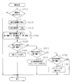
- the warning process shown in FIG. 2 is executed by the warning control device 100 at predetermined intervals.
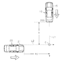
- this process is started, first, it is determined whether or not a moving body is detected by the detection device 200 (S100). More specifically, as shown in FIG. 3, when the host vehicle 10 moves backward in the direction of arrow R, the direction intersecting the course L ⁇ b> 1 of the host vehicle 10 by the detection device 200 provided at the rear of the host vehicle 10. It is determined whether or not a moving body that moves in the direction of the arrow F (for example, another vehicle 20) has been detected. And when a mobile body is not detected (S100: NO), this process is once complete
- the estimated crossing distance X is calculated based on the path L1 when the host vehicle 10 moves backward and the path L2 of the other vehicle 20 (strictly, the movement of the side surface 21 that is in the other vehicle 20 and faces the host vehicle 10). This is the distance from the predicted intersection position C to the rear end of the host vehicle.
- the estimated intersection distance X is detected by the position and traveling direction and speed of the other vehicle 20 detected by the detection device 200, the speed of the host vehicle detected by the vehicle speed sensor 210, and the yaw rate sensor 220 and the steering angle sensor 230. It is calculated based on the traveling direction of the own vehicle.
- step S200 corresponds to the process executed by the distance calculation unit.
- the estimated intersection time PT is a time until the other vehicle 20 reaches the predicted intersection position C from the current position.
- the estimated intersection time PT is calculated from the distance from the current position of the other vehicle 20 to the predicted intersection position C and the speed of the other vehicle 20.
- the process in step S300 corresponds to the process executed by the time calculation unit.
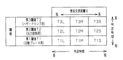
- the first threshold T1, the second threshold T2, and the third threshold T3 are set based on the estimated intersection distance X calculated in step S200 (S400).
- the first threshold value T1 to the third threshold value T3 are comparison determination values of the estimated intersection time PT calculated in step S300.
- the determination time is increased in the order of the first threshold T1, the second threshold T2, and the third threshold T3 (T1 ⁇ T2 ⁇ T3).
- the determination time for the second threshold T2 is variably set (T2L> T2M> T2S).
- the shorter the estimated intersection distance X the longer the determination time for the third threshold T3 is set (T3L> T3M> T3S).
- the process in step S400 corresponds to the process executed by the timing changing unit.
- step S500 it is next determined whether the estimated intersection time PT is shorter than the first threshold T1.
- S500 Deceleration control for decelerating the host vehicle 10 is executed as a warning operation. More specifically, in step S800, an automatic brake that forcibly activates the brake 910 of the host vehicle 10 is executed, so that the host vehicle 10 is decelerated and the present process is temporarily terminated.
- the buzzer 280, the display device 290, or an indicator may be used to notify the driver of the host vehicle 10 that a warning operation is being performed.
- the estimated intersection time PT exceeds the first threshold value T1 (S500: NO)
- the estimated intersection time PT is shorter than the second threshold T2 (S600: YES)
- a warning is given because the time until the host vehicle 10 and the other vehicle 20 intersect is relatively short and the risk of approach is high to some extent.
- deceleration control for decelerating the host vehicle 10 is executed. However, in the deceleration control performed when an affirmative determination is made in step S600, the deceleration of the host vehicle 10 is made slower than the deceleration control performed when an affirmative determination is made in step S500.
- an output suppression process for reducing the output of the internal combustion engine is executed (S900).
- This output suppression process is a process for fully closing the throttle valve 810.
- the buzzer 280, the display device 290, or an indicator may be used to notify the driver of the host vehicle 10 that a warning operation is being performed.
- the hazard lamp 270 of the host vehicle 10 is blinked as a warning operation, that is, the vehicle width lamp of the host vehicle 10 is blinked (S1000), and this process is temporarily terminated.
- the hazard lamp 270 may be blinked for a predetermined time, for example, or until the other vehicle 20 finishes passing on the course of the host vehicle 10.
- each process of step S500 to step S1000 corresponds to a process executed by the warning operation unit.
- the determination time is lengthened in the order of the first threshold value T1, the second threshold value T2, and the third threshold value T3. Therefore, as the estimated intersection time PT becomes shorter, each warning operation is performed in the order of blinking of the hazard lamp 270 in step S1000, output suppression processing in step S900, and automatic braking in step S800.
- an estimated intersection time PT which is the time until the other vehicle 20 reaches the expected intersection position C. And if this estimated intersection time PT becomes below a threshold value (1st threshold value T1, 2nd threshold value T2, 3rd threshold value T3), it will be judged that there exists a possibility that the own vehicle 10 and the other vehicle 20 may approach too much, and it is various.
- a warning action is performed. As shown in FIG. 4, these threshold values are set to a longer time as the estimated intersection distance X is shorter. Therefore, the higher the risk that the other vehicle 20 and the host vehicle 10 are too close, the higher the warning.
- the operation is executed at an earlier timing.
- the shorter the estimated intersection distance X that is, the shorter the distance between the other vehicle 20 and the own vehicle 10 when the other vehicle 20 crosses the own vehicle 10, the more excessive the other vehicle 20 and the own vehicle 10 are.
- the higher the risk of approaching the earlier the execution timing of the warning action. Therefore, for example, treatment for avoiding the approach between the other vehicle 20 and the host vehicle 10 can be performed at an earlier stage as the risk of approach is higher. Therefore, when the other vehicle 20 moving in the direction intersecting the course L1 of the host vehicle 10 and the host vehicle 10 approach each other, a warning operation is performed at an appropriate timing.
- the warning operation is performed at an appropriate timing according to the degree of danger of approach, so that it is possible to reduce the uncomfortable feeling felt by the driver.
- the hazard lamp 270 blinks as the first stage of the warning operation. Therefore, the approach to the own vehicle 10 can be alerted to the other vehicle 20. Therefore, for example, a signal can be issued that causes the other vehicle 20 to perform avoidance actions such as deceleration or course change.
- the own vehicle 10 and the other vehicle 20 When the estimated intersection time PT is equal to or shorter than the second threshold T2 or the first threshold T1, which is shorter than the third threshold T3, that is, when the first stage warning operation is performed, the own vehicle 10 and the other vehicle 20
- deceleration control for decelerating the host vehicle 10 is performed as the second stage of the warning operation.
- the driver of the host vehicle 10 can feel a sense of deceleration as a warning operation.
- the approach speed of the own vehicle 10 with respect to the other vehicle 20 falls by performing deceleration control, it can suppress that the own vehicle 10 approaches the other vehicle 20 too much.
- the output suppression process is executed as the first deceleration control.
- the estimated intersection time PT is equal to or shorter than the first threshold T1 shorter than the second threshold T2
- Automatic braking is executed as second deceleration control for further decelerating 10. By executing this automatic braking, the approach speed of the host vehicle 10 with respect to the other vehicle 20 can be greatly reduced.
- the threshold value is increased as the estimated intersection distance X is shorter. Therefore, the first stage warning operation and the second stage warning operation are performed as the estimated intersection distance X is shorter.
- the execution timing of each is advanced. Therefore, the first stage warning action and the second stage warning action are executed earlier as the estimated intersection distance X is shorter and the risk of the host vehicle 10 and the other vehicle 20 approaching each other is higher. For example, the time for avoiding that the own vehicle 10 and the other vehicle 20 approach can be ensured appropriately.
- the host vehicle 10 is determined from the expected intersection position C between the course L1 of the host vehicle 10 and the course L2 of the other vehicle 20.
- the estimated intersection distance X which is the distance up to, is calculated. As the estimated intersection distance X is shorter, the warning action is executed earlier. Therefore, when the other vehicle 20 moving in the direction intersecting the course L1 of the host vehicle 10 and the host vehicle 10 approach each other, a warning operation can be performed at an appropriate timing. In addition, if the warning operation is executed early even though the risk of approach of the other vehicle 20 and the host vehicle 10 is not so high, the driver of the host vehicle 10 may feel uncomfortable. In this regard, in the present embodiment, since the warning operation is performed at an appropriate timing according to the risk of approach, it is possible to reduce the uncomfortable feeling felt by the driver.
- An estimated intersection time PT which is a time until the other vehicle 20 reaches the predicted intersection position C, is calculated, and a warning operation is performed when the estimated intersection time PT is equal to or less than a predetermined threshold value.
- the threshold value is variably set so that the longer the estimated intersection distance X is, the longer the threshold value is. Therefore, the warning operation can be executed at an earlier timing as the degree of risk that the other vehicle 20 and the host vehicle 10 approach excessively increases.
- the hazard lamp 270 blinks as the first stage of the warning operation. Therefore, it is possible to alert the other vehicle 20 to approach the host vehicle 10.
- the deceleration control which decelerates the own vehicle 10 is performed as a 2nd step of a warning operation. . Therefore, the driver of the host vehicle 10 can feel a sense of deceleration as a warning operation. Moreover, since the approach speed of the own vehicle 10 with respect to the other vehicle 20 falls, it can suppress that the own vehicle 10 approaches the other vehicle 20 excessively.
- the threshold values are changed so that the execution timing of the first-stage warning operation and the second-stage warning operation becomes earlier as the estimated intersection distance X is shorter. Therefore, the higher the risk of approach, the earlier the first stage warning operation and the second stage warning operation can be performed.
- deceleration control control for reducing the output of the internal combustion engine 15 mounted on the host vehicle 10 is performed. Therefore, when deceleration control is executed, the output of the internal combustion engine 15 is reduced, and the host vehicle 10 can be decelerated.
- deceleration control automatic brake control for operating the brake 910 of the host vehicle 10 is performed. Accordingly, when deceleration control is executed, the brake 910 of the host vehicle 10 operates. Therefore, the host vehicle 10 can be further decelerated as compared with the execution of the output suppression process described above.
- the hazard lamp 270 blinks as a warning operation
- a condition regarding the blinking may be added. For example, if the host vehicle 10 is stopped, the other vehicle 20 and the host vehicle 10 do not contact on the route L1 of the host vehicle 10. Therefore, the hazard lamp 270 may be blinked while the host vehicle 10 is traveling.
- the blinking of the hazard lamp may be performed when the stopped vehicle 10 is predicted to change to the running state.
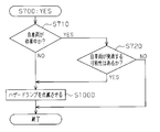
- This modification can be implemented by adding new steps S710 and S720 to the warning process shown in FIG. That is, as shown in FIG. 5, when it is determined in step S700 shown in FIG. 2 that the estimated intersection time PT is equal to or shorter than the third threshold value T3, it is determined based on the detection value of the vehicle speed sensor 210 or the like. It is determined whether or not the vehicle 10 is stopped (S710). When it is determined that the vehicle is not stopped, that is, when it is determined that the vehicle is traveling (S710: NO), the hazard lamp 270 blinks by performing the process of step S1000 described above.
- step S720 it is determined whether or not the host vehicle 10 may start (S720).
- the determination in step S720 can be performed as appropriate. For example, when it is determined that the operation amount of the accelerator pedal has changed to “0” or more based on the detection value of the accelerator operation amount sensor 250, it can be determined that the host vehicle 10 may start. . Also, when the amount of operation of the brake pedal that was stepped on to stop the host vehicle 10 decreases, or when the brake pressure decreases and the braking force of the brake 910 decreases, the host vehicle 10 starts. It can be determined that there is a possibility of doing.
- the warning process is temporarily terminated without blinking the hazard lamp 270.
- the host vehicle 10 is likely to start (S720: YES)
- the lamp 270 is blinked to end the warning process once.
- step S100 shown in FIG. 2 When it is determined in step S100 shown in FIG. 2 that a moving body has been detected, the buzzer 280, the display device 290, or the indicator is used to inform the driver of the host vehicle 10 of the moving body ( You may make it alert
- the buzzer 280, the display device 290, or the indicator is used to inform the driver of the host vehicle 10 of the moving body ( You may make it alert
- notification to the driver using the buzzer 280, the display device 290, or an indicator. May be performed.
- the buzzer 280, the display device 290, or the driver using the indicator is notified. Also good.
- the first threshold value T1, the second threshold value T2, and the third threshold value T3 may be continuously changed according to the length of the estimated intersection distance X. For example, as shown in FIG. 6, if the estimated crossing distance X is the same, the determination time is set to be longer in the order of the first threshold T1, the second threshold T2, and the third threshold T3. Then, the determination time set to the first threshold T1 is variably set longer as the estimated intersection distance X becomes shorter. Further, the determination time set to the second threshold T2 is variably set as the estimated intersection distance X becomes shorter. Further, the determination time set to the third threshold T3 is variably set as the estimated intersection distance X becomes shorter. According to this modification, each threshold value can be set more precisely according to the length of the estimated intersection distance X.
- only the hazard lamp 270 may be blinked or only the various deceleration controls described above may be performed.
- the warning operation only the blinking of the hazard lamp 270 and the output suppression process described above may be performed. Further, only the blinking of the hazard lamp 270 and the above-described automatic braking may be performed as the warning operation. Further, as the warning operation, only the output suppression process described above may be performed, or only the automatic brake described above may be performed.
- the warning action is performed in the order of blinking of the hazard lamp 270, output suppression processing, and automatic braking.
- a plurality of processes may be performed simultaneously as a warning operation. For example, as shown in FIG. 7, a threshold value T corresponding to the first to third threshold values is set. That is, the threshold value T is set such that the determination time becomes longer as the estimated intersection distance X is shorter.
- a warning operation is performed. Any one of the following (A) to (D) may be performed as a warning operation simultaneously performed at this time.
- the throttle valve 810 was fully closed.
- the opening degree of the throttle valve 810 may be made smaller than before the output suppression process is performed, instead of being fully closed. Even in this case, the output of the internal combustion engine 15 can be reduced compared to before the output suppression process is executed. Further, the engine output may be reduced by adjusting another engine control amount different from the opening degree of the throttle valve 810. Examples of such other engine control amounts include ignition timing, exhaust gas recirculation amount, and supercharging efficiency of the supercharger.
- the own vehicle 10 may be decelerated by reducing the power supplied to the electric motor to reduce the output of the prime mover.
- the deceleration control a method other than the above-described reduction in the output of the prime mover or deceleration by brake operation may be employed.
- the host vehicle 10 may be decelerated by changing the gear ratio of a transmission provided between the prime mover and the drive wheels to increase the drive resistance of the drive wheels.
- the output suppression process described above may be performed only when the accelerator pedal is operated. Whether or not the accelerator pedal is being operated can be determined based on a detection value of the accelerator operation amount sensor 250.
- the above-described automatic braking may be performed only when it is determined that the braking force of the brake 910 is insufficient although the other vehicle 20 is approaching the host vehicle 10. For example, if it is determined in step S500 shown in FIG. 2 that the estimated intersection time PT is equal to or less than the first threshold value, whether or not the braking force is insufficient based on the detection value of the brake pressure sensor 260 is determined. Determine. If it is determined that the braking force is insufficient, automatic braking may be executed in step S800. The lack of braking force can be determined not only based on the value detected by the brake pressure sensor 260 but also based on the amount of operation of the brake pedal.
- the estimated intersection time PT is calculated in order to determine whether or not the host vehicle 10 and the other vehicle 20 are approaching each other to the extent that a warning action is necessary. Good. For example, the distance from the current position of the other vehicle 20 to the predicted intersection position C is calculated. The calculated distance may be used as a substitute value for the estimated intersection time PT.
- the detection device 200 is provided in the rear bumper of the host vehicle 10 so that a moving body behind the host vehicle 10 is detected.
- a detection device 200 may be provided in the front part (front bumper, front grill, etc.) of the host vehicle 10 to detect a moving body in front of the host vehicle 10. Also in this case, the same effect as the above embodiment can be obtained.
Landscapes
- Physics & Mathematics (AREA)
- General Physics & Mathematics (AREA)
- Electromagnetism (AREA)
- Traffic Control Systems (AREA)
Abstract
Description
Claims (9)
- 自車両の進路に対して交差する方向に移動する移動体を検出する検出部と、
自車両の進路と前記移動体の進路との予想交差位置から自車両までの距離である交差距離を算出する距離算出部と、
自車両と前記移動体とが接近するときに警告動作を行う警告動作部と、
前記交差距離が短いときほど前記警告動作の実行タイミングを早くするタイミング変更部と、を備える
車両用警告装置。 - 前記移動体が前記予想交差位置に到達するまでの時間である交差時間を算出する時間算出部を備え、
前記警告動作部は、前記交差時間が閾値以下のときに前記警告動作を行い、
前記タイミング変更部は、前記交差距離が短いときほど前記閾値を長い時間に設定する
請求項1に記載の車両用警告装置。 - 前記警告動作部は、前記警告動作としてハザードランプを点滅させる
請求項1または2に記載の車両用警告装置。 - 前記警告動作部は、前記警告動作として自車両を減速させる減速制御を行う
請求項1または2に記載の車両用警告装置。 - 前記警告動作部は、前記警告動作の第1段階としてハザードランプの点滅を行い、この第1段階の警告動作を行うときよりも自車両と前記移動体とが接近しているときには、前記警告動作の第2段階として自車両を減速させる減速制御を行い、
前記タイミング変更部は、前記交差距離が短いときほど前記第1段階の警告動作及び前記第2段階の警告動作の実行タイミングをそれぞれ早くする
請求項1または2に記載の車両用警告装置。 - 前記警告動作部は、前記ハザードランプの点滅を自車両の走行中に行う
請求項3または5に記載の車両用警告装置。 - 前記警告動作部は、前記ハザードランプの点滅を、停車中の自車両が走行状態に変化すると予測されるときに行う
請求項3または5に記載の車両用警告装置。 - 前記警告動作部は、前記減速制御として、自車両に搭載された原動機の出力を低下させる制御を行う
請求項4または5に記載の車両用警告装置。 - 前記警告動作部は、前記減速制御として、自車両の制動装置を作動させる制御を行う
請求項4または5に記載の車両用警告装置。
Priority Applications (5)
| Application Number | Priority Date | Filing Date | Title |
|---|---|---|---|
| PCT/JP2012/066260 WO2014002187A1 (ja) | 2012-06-26 | 2012-06-26 | 車両用警告装置 |
| US14/408,414 US9330572B2 (en) | 2012-06-26 | 2012-06-26 | Vehicle warning device |
| JP2014522269A JPWO2014002187A1 (ja) | 2012-06-26 | 2012-06-26 | 車両用警告装置 |
| CN201280073895.0A CN104380362A (zh) | 2012-06-26 | 2012-06-26 | 车辆用警告装置 |
| DE201211006618 DE112012006618T5 (de) | 2012-06-26 | 2012-06-26 | Fahrzeugwarneinrichtung |
Applications Claiming Priority (1)
| Application Number | Priority Date | Filing Date | Title |
|---|---|---|---|
| PCT/JP2012/066260 WO2014002187A1 (ja) | 2012-06-26 | 2012-06-26 | 車両用警告装置 |
Publications (1)
| Publication Number | Publication Date |
|---|---|
| WO2014002187A1 true WO2014002187A1 (ja) | 2014-01-03 |
Family
ID=49782420
Family Applications (1)
| Application Number | Title | Priority Date | Filing Date |
|---|---|---|---|
| PCT/JP2012/066260 Ceased WO2014002187A1 (ja) | 2012-06-26 | 2012-06-26 | 車両用警告装置 |
Country Status (5)
| Country | Link |
|---|---|
| US (1) | US9330572B2 (ja) |
| JP (1) | JPWO2014002187A1 (ja) |
| CN (1) | CN104380362A (ja) |
| DE (1) | DE112012006618T5 (ja) |
| WO (1) | WO2014002187A1 (ja) |
Cited By (2)
| Publication number | Priority date | Publication date | Assignee | Title |
|---|---|---|---|---|
| JP2016115129A (ja) * | 2014-12-15 | 2016-06-23 | トヨタ自動車株式会社 | 警報装置 |
| JP2017219466A (ja) * | 2016-06-09 | 2017-12-14 | 株式会社デンソー | レーダ装置 |
Families Citing this family (7)
| Publication number | Priority date | Publication date | Assignee | Title |
|---|---|---|---|---|
| WO2015174093A1 (ja) * | 2014-05-16 | 2015-11-19 | パナソニックIpマネジメント株式会社 | 車載用表示装置、車載用表示装置の制御方法、プログラム |
| JP6775285B2 (ja) * | 2015-09-24 | 2020-10-28 | アルパイン株式会社 | 後側方車両検知警報装置 |
| CN106251667B (zh) * | 2016-08-18 | 2019-04-02 | 深圳市永兴元科技股份有限公司 | 车辆驾驶提示方法及装置 |
| CN106251668B (zh) * | 2016-08-18 | 2019-02-26 | 深圳市永兴元科技股份有限公司 | 车辆驾驶提示方法及装置 |
| US11366476B2 (en) * | 2018-01-15 | 2022-06-21 | Uatc, Llc | Systems and methods for deploying warning devices from an autonomous vehicle |
| CN114155707A (zh) * | 2021-05-31 | 2022-03-08 | 浙江柯瑞普科技有限公司 | 一种智能交通安全行驶视觉警示系统和方法 |
| CN116543542B (zh) * | 2023-07-03 | 2023-10-27 | 云南省交通规划设计研究院有限公司 | 一种隧道入口运行风险定向预警设备布设方法 |
Citations (4)
| Publication number | Priority date | Publication date | Assignee | Title |
|---|---|---|---|---|
| JP2004310260A (ja) * | 2003-04-03 | 2004-11-04 | Nissan Motor Co Ltd | 一時停止警報装置 |
| JP2005145337A (ja) * | 2003-11-18 | 2005-06-09 | Nissan Motor Co Ltd | 車線逸脱防止装置 |
| JP2007207047A (ja) * | 2006-02-03 | 2007-08-16 | Nissan Motor Co Ltd | 車両用停止警報装置および車両用停止警報方法 |
| JP2011113275A (ja) * | 2009-11-26 | 2011-06-09 | Daihatsu Motor Co Ltd | 運転支援装置 |
Family Cites Families (22)
| Publication number | Priority date | Publication date | Assignee | Title |
|---|---|---|---|---|
| JPS5435172B2 (ja) | 1972-09-30 | 1979-10-31 | ||
| JP3189560B2 (ja) * | 1994-03-25 | 2001-07-16 | 株式会社デンソー | 車間距離検知装置および車間距離警報装置 |
| US8000897B2 (en) * | 1997-10-22 | 2011-08-16 | Intelligent Technologies International, Inc. | Intersection collision avoidance techniques |
| JP4807482B2 (ja) | 2001-07-04 | 2011-11-02 | 三菱自動車工業株式会社 | 障害物情報呈示装置 |
| JP2004268720A (ja) | 2003-03-07 | 2004-09-30 | Calsonic Kansei Corp | ハザードランプ制御装置 |
| US8629800B2 (en) * | 2004-09-30 | 2014-01-14 | The Boeing Company | Ground vehicle collision prevention systems and methods |
| JP2006315489A (ja) | 2005-05-11 | 2006-11-24 | Toyota Motor Corp | 車両周囲警報装置 |
| JP4752679B2 (ja) * | 2005-10-13 | 2011-08-17 | 日産自動車株式会社 | 車両用運転操作補助装置 |
| JP2007112297A (ja) | 2005-10-20 | 2007-05-10 | Denso Corp | 車両用障害物衝突回避システム |
| JP4775121B2 (ja) * | 2006-06-05 | 2011-09-21 | 株式会社デンソー | 車両用運転支援システム |
| JP4999512B2 (ja) * | 2007-03-26 | 2012-08-15 | スタンレー電気株式会社 | 車両接近警報装置 |
| DE102007015032A1 (de) * | 2007-03-29 | 2008-01-10 | Daimlerchrysler Ag | Verfahren zur Bewertung der Kritikalität einer Verkehrssituation und Vorrichtung zur Kollisionsvermeidung oder Kollisionsfolgenminderung |
| JP2008254710A (ja) | 2007-04-09 | 2008-10-23 | Fujitsu Ten Ltd | 障害物検知装置 |
| JP4811343B2 (ja) * | 2007-05-11 | 2011-11-09 | トヨタ自動車株式会社 | 物体検出装置 |
| JP4604103B2 (ja) * | 2008-03-31 | 2010-12-22 | トヨタ自動車株式会社 | 交差点見通し検出装置 |
| JP4952637B2 (ja) | 2008-04-04 | 2012-06-13 | トヨタ自動車株式会社 | 駐車支援装置 |
| JP5262394B2 (ja) | 2008-07-25 | 2013-08-14 | トヨタ自動車株式会社 | 衝突予測装置 |
| EP2211322B1 (en) * | 2009-01-26 | 2016-11-16 | Volvo Car Corporation | Method and system for forward collision avoidance in an automotive vehicle |
| JP5278292B2 (ja) * | 2009-11-27 | 2013-09-04 | 株式会社デンソー | 情報提示装置 |
| JP2011209849A (ja) * | 2010-03-29 | 2011-10-20 | Daihatsu Motor Co Ltd | 運転支援方法および運転支援装置 |
| JP5403158B2 (ja) * | 2011-04-11 | 2014-01-29 | トヨタ自動車株式会社 | 車両制御装置及び車両制御方法 |
| KR20140020361A (ko) | 2011-04-20 | 2014-02-18 | 도요타 지도샤(주) | 차량용 주변 경계 장치 |
-
2012
- 2012-06-26 CN CN201280073895.0A patent/CN104380362A/zh active Pending
- 2012-06-26 WO PCT/JP2012/066260 patent/WO2014002187A1/ja not_active Ceased
- 2012-06-26 JP JP2014522269A patent/JPWO2014002187A1/ja active Pending
- 2012-06-26 US US14/408,414 patent/US9330572B2/en not_active Expired - Fee Related
- 2012-06-26 DE DE201211006618 patent/DE112012006618T5/de not_active Withdrawn
Patent Citations (4)
| Publication number | Priority date | Publication date | Assignee | Title |
|---|---|---|---|---|
| JP2004310260A (ja) * | 2003-04-03 | 2004-11-04 | Nissan Motor Co Ltd | 一時停止警報装置 |
| JP2005145337A (ja) * | 2003-11-18 | 2005-06-09 | Nissan Motor Co Ltd | 車線逸脱防止装置 |
| JP2007207047A (ja) * | 2006-02-03 | 2007-08-16 | Nissan Motor Co Ltd | 車両用停止警報装置および車両用停止警報方法 |
| JP2011113275A (ja) * | 2009-11-26 | 2011-06-09 | Daihatsu Motor Co Ltd | 運転支援装置 |
Cited By (2)
| Publication number | Priority date | Publication date | Assignee | Title |
|---|---|---|---|---|
| JP2016115129A (ja) * | 2014-12-15 | 2016-06-23 | トヨタ自動車株式会社 | 警報装置 |
| JP2017219466A (ja) * | 2016-06-09 | 2017-12-14 | 株式会社デンソー | レーダ装置 |
Also Published As
| Publication number | Publication date |
|---|---|
| JPWO2014002187A1 (ja) | 2016-05-26 |
| CN104380362A (zh) | 2015-02-25 |
| US9330572B2 (en) | 2016-05-03 |
| DE112012006618T5 (de) | 2015-04-02 |
| US20150116102A1 (en) | 2015-04-30 |
Similar Documents
| Publication | Publication Date | Title |
|---|---|---|
| WO2014002187A1 (ja) | 車両用警告装置 | |
| JP6844714B2 (ja) | 自動運転車両の制御方法および制御装置 | |
| CN106627531B (zh) | 用于车辆自动紧急制动的控制方法、装置及车辆 | |
| JP6090065B2 (ja) | 運転支援装置 | |
| JP5677154B2 (ja) | 車両用運転支援装置 | |
| WO2008001874A1 (en) | Vehicle deceleration controller | |
| CN110654377A (zh) | 一种车辆防撞控制方法及控制系统 | |
| JP6443406B2 (ja) | 車両用警報制御装置 | |
| JP5768891B2 (ja) | 車両の運転支援システム | |
| US20140200799A1 (en) | Vehicle control apparatus | |
| JP2010030396A (ja) | 車両用安全制御装置 | |
| JP2022024322A (ja) | 衝突回避支援装置 | |
| JP2022024323A (ja) | 衝突回避支援装置 | |
| US10723349B2 (en) | Vehicle control device and control method | |
| WO2013098996A1 (ja) | 車両の運転支援装置 | |
| JP6132392B2 (ja) | 運転支援制御装置 | |
| JP4840427B2 (ja) | 車両制御装置 | |
| JP2006199233A (ja) | 車両用安全制御装置 | |
| KR100851831B1 (ko) | 차량의 충돌 방지장치 및 그것의 제어방법 | |
| JP2022111506A (ja) | 車両制御装置 | |
| JP2014008814A (ja) | 衝突回避装置 | |
| CN202413789U (zh) | 车辆用驾驶辅助装置 | |
| US8954250B2 (en) | Vehicular control apparatus and vehicular control method | |
| JP2011126319A (ja) | 車両の走行安全制御装置 | |
| JP2016122456A (ja) | 車両の運転支援装置 |
Legal Events
| Date | Code | Title | Description |
|---|---|---|---|
| 121 | Ep: the epo has been informed by wipo that ep was designated in this application |
Ref document number: 12879981 Country of ref document: EP Kind code of ref document: A1 |
|
| ENP | Entry into the national phase |
Ref document number: 2014522269 Country of ref document: JP Kind code of ref document: A |
|
| WWE | Wipo information: entry into national phase |
Ref document number: 14408414 Country of ref document: US |
|
| WWE | Wipo information: entry into national phase |
Ref document number: 1120120066189 Country of ref document: DE Ref document number: 112012006618 Country of ref document: DE |
|
| 122 | Ep: pct application non-entry in european phase |
Ref document number: 12879981 Country of ref document: EP Kind code of ref document: A1 |