WO2014002178A1 - データ収集装置及びデータ収集プログラム - Google Patents
データ収集装置及びデータ収集プログラム Download PDFInfo
- Publication number
- WO2014002178A1 WO2014002178A1 PCT/JP2012/066200 JP2012066200W WO2014002178A1 WO 2014002178 A1 WO2014002178 A1 WO 2014002178A1 JP 2012066200 W JP2012066200 W JP 2012066200W WO 2014002178 A1 WO2014002178 A1 WO 2014002178A1
- Authority
- WO
- WIPO (PCT)
- Prior art keywords
- data
- time
- unit
- collection
- read
- Prior art date
- Legal status (The legal status is an assumption and is not a legal conclusion. Google has not performed a legal analysis and makes no representation as to the accuracy of the status listed.)
- Ceased
Links
Images


Classifications
-
- G—PHYSICS
- G06—COMPUTING OR CALCULATING; COUNTING
- G06F—ELECTRIC DIGITAL DATA PROCESSING
- G06F16/00—Information retrieval; Database structures therefor; File system structures therefor
- G06F16/20—Information retrieval; Database structures therefor; File system structures therefor of structured data, e.g. relational data
- G06F16/28—Databases characterised by their database models, e.g. relational or object models
- G06F16/284—Relational databases
- G06F16/285—Clustering or classification
-
- G—PHYSICS
- G05—CONTROLLING; REGULATING
- G05B—CONTROL OR REGULATING SYSTEMS IN GENERAL; FUNCTIONAL ELEMENTS OF SUCH SYSTEMS; MONITORING OR TESTING ARRANGEMENTS FOR SUCH SYSTEMS OR ELEMENTS
- G05B19/00—Program-control systems
- G05B19/02—Program-control systems electric
- G05B19/418—Total factory control, i.e. centrally controlling a plurality of machines, e.g. direct or distributed numerical control [DNC], flexible manufacturing systems [FMS], integrated manufacturing systems [IMS] or computer integrated manufacturing [CIM]
- G05B19/4183—Total factory control, i.e. centrally controlling a plurality of machines, e.g. direct or distributed numerical control [DNC], flexible manufacturing systems [FMS], integrated manufacturing systems [IMS] or computer integrated manufacturing [CIM] characterised by data acquisition, e.g. workpiece identification
-
- G—PHYSICS
- G06—COMPUTING OR CALCULATING; COUNTING
- G06Q—INFORMATION AND COMMUNICATION TECHNOLOGY [ICT] SPECIALLY ADAPTED FOR ADMINISTRATIVE, COMMERCIAL, FINANCIAL, MANAGERIAL OR SUPERVISORY PURPOSES; SYSTEMS OR METHODS SPECIALLY ADAPTED FOR ADMINISTRATIVE, COMMERCIAL, FINANCIAL, MANAGERIAL OR SUPERVISORY PURPOSES, NOT OTHERWISE PROVIDED FOR
- G06Q10/00—Administration; Management
- G06Q10/06—Resources, workflows, human or project management; Enterprise or organisation planning; Enterprise or organisation modelling
-
- H—ELECTRICITY
- H04—ELECTRIC COMMUNICATION TECHNIQUE
- H04Q—SELECTING
- H04Q9/00—Arrangements in telecontrol or telemetry systems for selectively calling a substation from a main station, in which substation desired apparatus is selected for applying a control signal thereto or for obtaining measured values therefrom
-
- G—PHYSICS
- G05—CONTROLLING; REGULATING
- G05B—CONTROL OR REGULATING SYSTEMS IN GENERAL; FUNCTIONAL ELEMENTS OF SUCH SYSTEMS; MONITORING OR TESTING ARRANGEMENTS FOR SUCH SYSTEMS OR ELEMENTS
- G05B2219/00—Program-control systems
- G05B2219/30—Nc systems
- G05B2219/37—Measurements
- G05B2219/37532—Synchronized data acquisition
-
- G—PHYSICS
- G05—CONTROLLING; REGULATING
- G05B—CONTROL OR REGULATING SYSTEMS IN GENERAL; FUNCTIONAL ELEMENTS OF SUCH SYSTEMS; MONITORING OR TESTING ARRANGEMENTS FOR SUCH SYSTEMS OR ELEMENTS
- G05B2219/00—Program-control systems
- G05B2219/30—Nc systems
- G05B2219/37—Measurements
- G05B2219/37533—Real time processing of data acquisition, monitoring
-
- H—ELECTRICITY
- H04—ELECTRIC COMMUNICATION TECHNIQUE
- H04Q—SELECTING
- H04Q2209/00—Arrangements in telecontrol or telemetry systems
- H04Q2209/10—Arrangements in telecontrol or telemetry systems using a centralized architecture
-
- H—ELECTRICITY
- H04—ELECTRIC COMMUNICATION TECHNIQUE
- H04Q—SELECTING
- H04Q2209/00—Arrangements in telecontrol or telemetry systems
- H04Q2209/30—Arrangements in telecontrol or telemetry systems using a wired architecture
-
- Y—GENERAL TAGGING OF NEW TECHNOLOGICAL DEVELOPMENTS; GENERAL TAGGING OF CROSS-SECTIONAL TECHNOLOGIES SPANNING OVER SEVERAL SECTIONS OF THE IPC; TECHNICAL SUBJECTS COVERED BY FORMER USPC CROSS-REFERENCE ART COLLECTIONS [XRACs] AND DIGESTS
- Y02—TECHNOLOGIES OR APPLICATIONS FOR MITIGATION OR ADAPTATION AGAINST CLIMATE CHANGE
- Y02P—CLIMATE CHANGE MITIGATION TECHNOLOGIES IN THE PRODUCTION OR PROCESSING OF GOODS
- Y02P90/00—Enabling technologies with a potential contribution to greenhouse gas [GHG] emissions mitigation
- Y02P90/02—Total factory control, e.g. smart factories, flexible manufacturing systems [FMS] or integrated manufacturing systems [IMS]
Definitions
- the present invention is widely used for control of industrial systems such as FA field including assembly work of steel and paper plant and automobile industry, PA field such as chemical plant, water supply and sewage system and other public systems.
- the present invention relates to a data collection device and a data collection program for collecting data from a device.
- a general control system for controlling a controlled object such as a plant device includes a plurality of control devices connected via a network, and transfers control information between the control devices via the network. There are those that control plant equipment.
- monitor plant equipment by collecting data such as process values from the control device via this network.
- data is stored while controlling the plant equipment.
- the stored data is analyzed to investigate the cause of the abnormal event that occurred. It can be useful for planning countermeasures. Therefore, it is necessary to quickly collect data of the control device.
- control information output by the control device to the steel plant is collected as binary data
- event information of the steel plant controlled by the control information output by the control device is collected as binary data, which is collected at the same time.
- Adds a common key to the binary data of the control information and the binary data of the event information accumulates the binary data of the control information to which the common key is added, and stores the binary data of the event information to which the common key is added.
- a network card provided in a recent control device has a built-in memory for data sharing, and a plurality of controls can be performed by transferring data stored in the memory using DMA (Direct Memory Access). Some devices transfer large amounts of data between devices at high speed.
- DMA Direct Memory Access
- the present invention has been made in view of the above problems, and it is an object of the present invention to provide a data collection device and a data collection program that collect data quickly with a simple configuration regardless of the amount of data.
- a first feature of the data collection device is that a storage unit for storing data transmitted by scanning between a plurality of control devices and a storage area of the storage unit in a plurality of groups. And dividing the storage area of the group into a plurality of subgroups, and based on the data transfer rate characteristics with respect to the size of the data, the one or more subdivisions of the divided subareas are prevented so as not to decrease the data reading speed.
- a schedule generation unit that generates a schedule for reading the data from the storage unit per unit time; and the generated schedule. Based on the module, in that and a data reading unit for reading the data from the storage unit.
- a second feature of the data collection device is that the time calculation for calculating the time required for reading the data per unit time as the required read time based on the schedule generated by the schedule generation unit. And a determination unit that determines whether or not the data can be read within the unit time based on the required read time calculated by the time calculation unit, and the data reading unit includes: When the determination unit determines that the data can be read within the unit time, the data is read from the storage unit.
- a third feature of the data collection device is that the time calculation unit calculates a value obtained by multiplying the number of collection groups per unit time in the schedule generated by the schedule generation unit by a data transfer rate. It is to calculate the reading time.
- a fourth feature of the data collection device is that, when the required reading time calculated by the time calculation unit is equal to or more than a threshold time obtained by subtracting a predetermined margin time from a unit time, It is determined that the data cannot be read within the unit time, and a warning is issued.
- a fifth feature of the data collection device is that, when the data requested to be read is not included in the selected subgroup, the schedule generation unit counts the number of collection groups within the unit time. The schedule is generated again so that the requested data is read from the storage unit in the time zone with the smallest number.
- a first feature of the data collection program is a storage step of causing a computer to store data to be scanned and transmitted between a plurality of control devices in a storage unit, and storage of the storage unit
- the area is divided into a plurality of groups, the storage area of the group is further divided into a plurality of subgroups, and the division is performed so as not to reduce the data reading speed based on the data transfer speed characteristics with respect to the data size.
- a group selection step of selecting one or more selected subgroups as a collection group that is a unit for continuously reading data within the group, the number of subgroups selected as the collection group, and a collection for collecting the data Based on the cycle, a schedule for reading out the data from the storage unit every unit time is generated.
- a schedule generating step for, on the basis of the generated schedule is to be executed and a data reading step of reading the data from the storage unit.
- a second feature of the data collection program is that the time calculation for calculating the time required to read the data per unit time as the required read time based on the schedule generated by the schedule generation step.
- a step of determining whether or not the data can be read within the unit time based on the required read time calculated by the time calculating step, and the data reading step includes: When it is determined by the determination step that the data can be read within the unit time, the data is read from the storage unit.
- a third feature of the data collection program according to the present invention is that the time calculation step is configured such that the required number is a value obtained by multiplying the number of collection groups per unit time in the schedule generated by the schedule generation step by a data transfer rate. It is to calculate the reading time.
- a fourth feature of the data collection program according to the present invention is that, in the determination step, the required read time calculated by the time calculation step is equal to or more than a threshold time obtained by subtracting a predetermined margin time from a unit time. It is determined that the data cannot be read within the unit time, and a warning is issued.
- a fifth feature of the data collection program according to the present invention is that, in the schedule generation step, when the data requested to be read is not included in the selected subgroup, the number of the collection groups in the unit time. The schedule is generated again so that the requested data is read from the storage unit in the time zone with the smallest number.
- data can be collected quickly with a simple configuration regardless of the amount of data.
- FIG. 1 is a diagram showing a connection relationship of the data collection system according to the first embodiment of the present invention.
- the data collection system 1 includes control devices 21 to 22 and data collection devices 41 to 43, each via a control network 52. It is connected.
- the data collection system 1 includes a monitoring device 62 and is connected to the data collection devices 41 to 43 via the host network 51.
- control devices 21 to 22 are constituted by control controllers represented by, for example, PLC (Programmable Logic Controller).
- the data collection devices 41 to 43 collect data supplied from the control devices 21 to 22.
- the data refers to, for example, manufacturing instruction data, manufacturing performance data, alarm data, roll data, model calculation data, model learning data, constant data, parameter data when plant equipment of a hot rolling plant is to be controlled. These are various data relating to plant control equipment necessary for operating a hot rolling plant.
- the data collection devices 41 to 43 and the control devices 21 to 22 connected to the control network 52 have a common memory, and the control data is scanned and transmitted (cyclic transmission) between the respective devices. It functions as a network device.
- each common memory a transmission data area and a reception data area assigned to each device are provided. Thereby, for example, the data in the transmission data area of the control device 21 is transferred to a common memory in all devices connected to the control network 52 by one data transmission. The concept of this common memory scan transmission will be described later.
- the display device 61 includes an image output device such as an organic EL (electroluminescence) display or a liquid crystal display, and is connected to the monitoring device 62.
- the display device 61 displays an alarm or the like based on the output signal supplied from the monitoring device 62.
- the monitoring device 62 displays a plurality of data on the display device 61 based on the process data supplied from the data collection devices 41 to 43 so that the time axes coincide with each other.
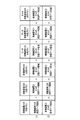
- FIG. 2 is a diagram schematically showing the concept of scan transmission of the common memory included in the control devices 21 to 22 and the data collection devices 41 to 43 of the data collection system 1 according to the first embodiment of the present invention.
- the data in the transmission data area of the control device 21 is all data connected to the same transmission path in one data transmission every control cycle.
- the data is transferred to a common memory of each of the devices (the control devices 22 to 23 and the data collection devices 41 to 43).
- the data in the transmission data area of the control device 22 is also transferred to the respective common memories of the control devices 21 and 23 and the data collection devices 41 to 43 every control cycle. .
- each common memory a transmission data area and a reception data area allocated to each apparatus are provided, and data is transferred to the common memory in all apparatuses by scan transmission. The same data can be shared between them.
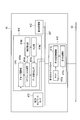
- FIG. 3 is a diagram showing a configuration of the data collection device 41 provided in the data collection system 1 according to the first embodiment of the present invention. Since the data collection devices 41 to 43 have the same configuration, the data collection device 41 will be described below as an example.
- the data collection device 41 includes a first network card 411, a second storage unit 412, a second network card 413, and a CPU 414, each of which has a bus 417. Connected through.
- the first network card 411 is an interface card for connecting to the control network 52, and includes a timer 411a, a first storage unit 411b, and a first storage control unit 411c. Yes.
- the first storage unit 411b is the shared memory described above, and stores data supplied from the control devices 21 to 22.
- the first storage control unit 411c When the data in the transmission data area of the first storage unit 411b is rewritten, the first storage control unit 411c performs scan transmission to another device or receives data area of the first storage unit 411b by scan transmission. Rewrite the data inside.
- the second storage unit 412 associates the time measured by the timer 411a with the data stored in the first storage unit 411b based on the instruction from the CPU 414, and stores it as process data.
- the second storage unit 412 stores a collection group pattern that is determined in advance based on the transfer rate characteristic with respect to the data size.
- the second network card 413 is an interface card for connecting to the upper network 51.
- the CPU 414 performs central control of the data collection device 41.
- the CPU 414 includes a group selection unit 414a, a schedule generation unit 414b, a time calculation unit 414c, a determination unit 414d, and a data reading unit 414e.
- the group selection unit 414a divides the storage area of the first storage unit 411b into a plurality of groups, and further divides the storage area of the group into a plurality of subgroups.
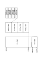
- FIG. 4 is a diagram showing a storage area of the first storage unit 411b included in the data collection device 41 of the data collection system 1 according to the first embodiment of the present invention.
- the group selection unit 414a stores 128 (bytes) from the beginning of the storage area of the first storage unit 411b as one block, and eight blocks 101 to 108 as one subgroup as a storage area. Split.
- the group selection unit 414a sets four subgroups, for example, subgroups 201 to 204 as one group 301.
- the group selection unit 414a divides the storage area hierarchically and, as will be described later, the stored data can be efficiently read out by being read out in units of subgroups.
- the group selection unit 414a is a unit for continuously reading data in one or more divided subgroups so as not to decrease the data reading speed based on the data transfer speed characteristic with respect to the data size.
- the data size may greatly affect the data transfer speed depending on communication standards, network settings, and the like. For example, as described above, when data is transferred using DMA, a large amount of data can be transferred at high speed. However, when transferring a small amount of data distributed and stored in the storage unit, DMA is used. In some cases, data transfer can be performed at higher speed. As described above, the data transfer speed characteristics may differ depending on the size of data to be transferred. Therefore, the group selection unit 414a selects a collection group that is a unit for continuous reading so as not to decrease the data reading speed, that is, not to decrease the reading speed from the first storage unit 411b.
- the schedule generation unit 414b generates a schedule for reading data from the first storage unit 411b for each unit time based on the number of subgroups selected as the collection group and the collection cycle for collecting data.
- the schedule generation unit 414b stores the data requested in the time zone with the smallest number of collection groups within the unit time in the first storage. The schedule is generated again so as to be read from the unit 411b.
- the time calculation unit 414c calculates the time required for reading data per unit time as the required read time based on the schedule generated by the schedule generation unit 414b. Specifically, the time calculation unit 414c calculates a value obtained by multiplying the number of collection groups per unit time in the schedule generated by the schedule generation unit 414b by the data transfer rate as the required read time.
- the determination unit 414d determines whether or not data can be read within a unit time based on the required read time calculated by the time calculation unit 414c. Specifically, the determination unit 414d cannot read data within the unit time when the required read time calculated by the time calculation unit 414c is equal to or longer than a threshold time obtained by subtracting a predetermined margin time from the unit time. It judges that it is, and issues a warning.
- the data reading unit 414e reads data from the storage unit when the determination unit 414d determines that data can be read within a unit time.
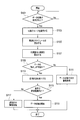
- FIG. 5 is a flowchart showing a processing procedure of processing executed by the data collection device 41 included in the data collection system 1 according to the first embodiment of the present invention.
- the group selection unit 414a of the CPU 414 selects a collection group (step S103). Specifically, the group selection unit 414a divides the storage area of the first storage unit 411b into a plurality of groups, and further divides the storage area of the group into a plurality of subgroups.
- the group selection unit 414a is a unit for continuously reading data in one or more divided subgroups so as not to reduce the data reading speed based on the transfer speed characteristics with respect to the data size. Select as a collection group.
- FIG. 6 is a diagram for explaining a pattern of collection groups selected by the group selection unit 414a included in the data collection device 41 of the data collection system 1 according to the first embodiment of the present invention.
- This collection group pattern is determined in advance based on the transfer rate characteristics with respect to the data size, and is stored in the second storage unit 412 as a collection group pattern.
- the group selection unit 414a selects a collection group based on the collection group pattern stored in the second storage unit 412.
- the group pattern 501 indicates an arrangement pattern of subgroups. “ ⁇ ” indicates a subgroup in which data is registered in the first storage unit 411b, and “ ⁇ ” indicates a subgroup in which data is not registered in the first storage unit 411b.
- the group pattern 501a is indicated by “ ⁇ ⁇ ”. This indicates that data is registered in the first subgroup 502a and no data is registered in the subgroups 502b to 502d.
- the collection group pattern 503a is indicated as “ ⁇ ”.
- the group pattern 501b is indicated by “ ⁇ ⁇ ”. This indicates that data is registered in the top subgroups 502a to 502b, and no data is registered in the subgroups 502c to 502d.
- the collection group pattern 503b is indicated as “ ⁇ ”.
- the group pattern 501c is indicated by “ ⁇ ⁇ ⁇ ⁇ ”. This indicates that data is registered in the subgroups 502a and 502c, and no data is registered in the subgroups 502b and 502c.
- the collection group pattern 503c is indicated as “ ⁇ ⁇ ⁇ ”.
- the transfer rate is higher when the subgroups 502a to 502c are read together with the subgroup 502b sandwiched between the subgroups 502a and 502c than when the subgroups 502a and 502c are read. That is, the reading speed is high.
- the group pattern 501d is indicated by “ ⁇ ⁇ ⁇ ”. This indicates that data is registered in the subgroups 502a and 502d, and no data is registered in the subgroups 502b and 502c.
- the collection group pattern 503d is indicated as “ ⁇ ⁇ ⁇ ”.
- the group pattern 501e is indicated by “ ⁇ ⁇ ”. This indicates that data is registered in the first subgroup 502a to 502c, and no data is registered in the subgroup 502d.
- the collection group pattern 503e is indicated as “ ⁇ ”.
- the group pattern 501f is indicated by “ ⁇ ⁇ ⁇ ”. This indicates that data is registered in the subgroups 502a, 502b, and 502d, and no data is registered in the subgroup 502c.
- the collection group pattern 503f is indicated as “ ⁇ ⁇ ⁇ ”.
- the transfer speed that is, the reading speed is higher when reading the subgroups 502a to 502d including the subgroup 502c than when reading the subgroups 502a, 502b, and 502d, respectively, in terms of transfer speed characteristics. .
- the group pattern 501g is indicated by “ ⁇ ”. This indicates that data is registered in all of the subgroups 502a to 502d.
- the group selection unit 414 a uses the collection group pattern based on the collection group pattern. Can be selected.
- the group selection unit 414a is a unit for continuously reading data in one or more divided subgroups so as not to decrease the data reading speed based on the transfer speed characteristics with respect to the data size. It can be selected as a collection group.
- the schedule generation unit 414b of the CPU 414 calculates an optimal schedule (step S105). Specifically, the schedule generation unit 414b is based on the number of subgroups selected as a collection group by the group selection unit 414a and the collection period for collecting data, and unit time (here, 1 msec) A schedule for reading data from the first storage unit 411b is generated every time.
- the schedule generation unit 414b determines the number of collection groups per unit time in the collection cycle as an integer value based on the value obtained by dividing the number of collection groups by the collection cycle for collecting data by the group selection unit 414a. To do. And the schedule production
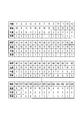
- FIG. 7 is a diagram illustrating an example of a schedule generated by the schedule generation unit 414b included in the data collection device 41 of the data collection system 1 according to the first embodiment of the present invention.
- the collection period for high speed collection is 2 msec
- the collection period for medium speed collection is 25 msec
- the collection period is 200 milliseconds.
- the number of collection groups selected by the group selection unit 414a is 114
- the number of collection groups for high-speed collection is "19”
- the number of collection groups for medium-speed collection is "55”
- low-speed collection it is assumed that the number of collection groups is “40”.
- the unit 414b determines the number of collection groups per unit time within the collection period as an integer value of 10,9.
- the schedule generation unit 414b sets the number of collection groups per unit time to “10” at time 1 and the number of collection groups per unit time at time 2, which is the next unit time. Arranged as “29”. Thereafter, similarly, the schedule generation unit 414b sets the number of collection groups per unit time to “10” at time 3 and the number of collection groups per unit time at time 4, which is the next unit time “ 9 ′′.
- the schedule generation unit 414b determines the number of collection groups per unit time in the collection cycle as an integer value as “3” or “2”.
- the schedule generation unit 414b sets “3” as the number of collection groups of 5 unit hours from the beginning, and “2” as the number of collection groups of 20 unit hours that follows, 3, 3, 3, 3, 3, 2,2,2,2,2,2,2,2,2,2,2,2,2,2,2,22
- the schedule generation unit 414b sets the number of collection groups per unit time to “3” during times 1 to 5, and collects per unit time during the next unit times 6 to 25.
- the number of groups is set as “2”.
- the schedule generation unit 414b sets the number of collection groups per unit time to “3” at times 26 to 30, and the collection groups per unit time at times 31 to 50, which are the next unit times. The number is set as “2”.
- the schedule generation unit 414b determines the number of collection groups per unit time in the collection period as an integer value, which is “1” or “0”.
- the schedule generation unit 414b determines that the number of collection groups for 40 unit hours from the beginning is “1”, and the number of collection groups for subsequent 160 unit hours is “0”.
- the schedule generation unit 414b sets the number of collection groups per unit time to “1” during the time 1 to 40, and collects per unit time during the next unit time 41 to 200.
- the number of groups is set as “0”.
- the schedule generation unit 414b sets the number of collection groups per unit time to “1” in the time 201 to 240, and the collection group per unit time in the next unit time 241 to 400. The number is set as “0”.
- the schedule generation unit 414b receives from the first storage unit 411b for each unit time based on the number of subgroups selected as a collection group by the group selection unit 414a and the collection cycle for collecting data. Generate a schedule to read data.
- the time calculation unit 414c of the CPU 414 calculates the time required to read out data for each unit time as the required read time based on the schedule generated by the schedule generation unit 414b (step S107). Specifically, the time calculation unit 414c sets the number of collection groups per unit time in the schedule generated by the schedule generation unit 414b as Cg, sets the data transfer rate according to the data transfer amount as Vt, and according to the data transfer amount.
- the required read time Tt is calculated using the following (Formula 1).
- the time calculation unit 414c measures the data transfer rate Vt for each number of collection groups by reading dummy data. For example, if the data transfer rate when reading 4096 bytes of data is 25 ⁇ s, the time calculation unit 414c sets the data transfer rate Vt when the number of collection groups is 4 to 25 ⁇ s. If the data transfer rate when reading 3072 bytes of data is 24 ⁇ s, the time calculation unit 414c sets the data transfer rate Vt when the number of collection groups is 3 to 24 ⁇ s.
- the time calculation unit 414c sets the data transfer rate Vt when the number of collection groups is 2 to 22 ⁇ s. If the data transfer rate when reading 1024 bytes of data is 20 ⁇ s, the time calculation unit 414c sets the data transfer rate Vt when the number of collection groups is 1 to 20 ⁇ s.
- the number of collection groups read at time 1 in the case of high-speed collection is “10”, and the breakdown is the number of collection groups from which 4096-byte data is read is “4”, 3072.
- the number of collection groups for reading byte data is “3”
- the number of collection groups for reading 2048 bytes of data is “2”
- the number of collection groups for reading 1028 bytes of data is “1”.
- the determination unit 414d of the CPU 414 determines whether or not the data can be read within the unit time based on the required read time T calculated by the time calculation unit 414c (step S109). . Specifically, the determination unit 414d determines whether or not the required read time T calculated by the time calculation unit 414c is equal to or longer than a threshold time (step S109).
- the threshold time Tb is a time obtained by subtracting a predetermined margin time Tc from the unit time.
- the threshold time Tb is 900 ⁇ sec.
- the required read time T at time 1 is 336 ⁇ s and is 900 ⁇ s or less which is the threshold time Tb, so that the determination unit 414 d can read data within a unit time. Is determined.
- the determination unit 414d issues an alarm indicating that data collection is not possible (step S111). Specifically, the determination unit 414d transmits an alarm signal indicating that data collection is impossible to the monitoring device 62, and the monitoring device 62 causes the display device 61 to display an alarm and output an alarm sound.
- step S113 determines the surplus capacity by subtracting the required reading time from the threshold time.
- the threshold time Tb is 900 ⁇ s and the required read time T is 336 ⁇ s, so the determination unit 414d calculates the surplus capacity as 564 ⁇ s.
- the determination unit 414d determines whether or not the load is within an allowable range (step S115). Specifically, the determination unit 414d determines that the load is within the allowable range when the surplus capacity calculated in step S113 is a positive value, and the surplus capacity calculated in step S113 is 0 ⁇ sec or less. When it is determined that the load exceeds the allowable range.
- step S115 when it is determined that the load exceeds the allowable range (in the case of NO), the determination unit 414d issues an overload alarm (step S117). Specifically, the determination unit 414d transmits an overload alarm signal to the monitoring device 62, and the monitoring device 62 causes the display device 61 to display an alarm and output an alarm sound.
- step S115 when it is determined in step S115 that the load is within the allowable range (in the case of YES), the data reading unit 414e starts data collection (step S119). Specifically, the data reading unit 414e reads data from the first storage unit 411b based on the schedule generated by the schedule generation unit 414b, and associates the time measured by the timer 411a with the read data. And stored in the second storage unit 412 as process data.
- the first storage that stores the data that is scanned and transmitted between the plurality of control devices 21 to 23. 411b and the storage area of the first storage unit 411b are divided into a plurality of groups, the storage area of the group is further divided into a plurality of subgroups, and data is read based on the data transfer rate characteristics with respect to the data size
- a group selection unit 414a that selects one or more divided subgroups as a collection group that is a unit for continuously reading data within the group, and the number of subgroups selected as the collection group.
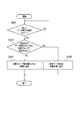
- FIG. 8 is a flowchart illustrating a processing procedure when a data item to be newly collected is added to the data collection device 41 included in the data collection system 1 according to the first embodiment of the present invention.
- the schedule generation unit 414b determines whether or not the data of the added data item is included in the collection group. Is determined (step S203).
- step S201 If it is determined in step S201 that the data of the added data item is included in the collection group (in the case of YES), the data of the added data item is already the target of data collection.
- the unit 414b adds the corresponding data item to the collection group (step S205).
- step S201 determines whether the data of the added data item is included in the collection group (in the case of NO). If it is determined in step S201 that the data of the added data item is not included in the collection group (in the case of NO), the data of the added data item is not a target for data collection. Need to regenerate the schedule.
- the schedule generation unit 414b adds the corresponding data item to the time with the smallest number of collection groups (step S207).
- the schedule generation unit 414 b performs the time 2 that is the time with the smallest number of collection groups among the time 1 and the time 2.
- a collection group including the data item to be added is added, and the number of collection groups is changed from “9” to “10”.
- the schedule generation unit 414b similarly changes the number of collection groups from “9” to “10” for times 4, 6, 8,.
- the schedule generation unit 414b generates the schedule again so that the requested data is read from the first storage unit 411b in the time zone with the smallest number of collection groups within the unit time.
- the data collection device 41 selects a collection group based on the collection group pattern shown in FIG. 6, but the collection group pattern is not limited to that shown in FIG. Absent.
- the group pattern 501c is indicated by “ ⁇ ⁇ ”, and in this case, the collection group pattern 503c is indicated by “ ⁇ ⁇ ⁇ ”. Due to the transfer rate characteristics, the subgroup 502a and 502c are read out together with the subgroup 502b sandwiched between the subgroup 502a and the subgroup 502c. When the speed is high, the collection group pattern 503c may be read as “ ⁇ ”, that is, only the subgroups 502a and 502c.
- the transfer speed when reading the subgroups 502a to 502c and the transfer speed when reading the subgroups 502a and 502c are measured, and the higher transfer speed is adopted. You may do it.
- the above-described embodiment can be realized by executing a data collection program installed in a computer. That is, for example, the data collection program may be read from a recording medium in which the data collection program is stored and executed by the CPU 414 to configure the data collection apparatus, or may be transmitted via a communication network.
- the data collection device may be configured by being installed and executed by the CPU 414.
- the present invention can be applied to a data collection system for collecting plant data.
Landscapes
- Engineering & Computer Science (AREA)
- Business, Economics & Management (AREA)
- Physics & Mathematics (AREA)
- General Physics & Mathematics (AREA)
- Theoretical Computer Science (AREA)
- Databases & Information Systems (AREA)
- Economics (AREA)
- Strategic Management (AREA)
- Quality & Reliability (AREA)
- Human Resources & Organizations (AREA)
- Entrepreneurship & Innovation (AREA)
- General Engineering & Computer Science (AREA)
- Automation & Control Theory (AREA)
- Development Economics (AREA)
- Educational Administration (AREA)
- Game Theory and Decision Science (AREA)
- Computer Networks & Wireless Communication (AREA)
- Manufacturing & Machinery (AREA)
- Marketing (AREA)
- Operations Research (AREA)
- Tourism & Hospitality (AREA)
- General Business, Economics & Management (AREA)
- Data Mining & Analysis (AREA)
- Testing And Monitoring For Control Systems (AREA)
- Selective Calling Equipment (AREA)
Description
<第1の実施形態>
図1は、本発明の第1の実施形態であるデータ収集システムの接続関係を示した図である。
ここで、データ転送速度をVtは、ネットワークカードの転送速度特性等によって異なるので、時間算出部414cは、ダミーのデータを読み込むことにより、収集グループ数毎のデータ転送速度Vtを測定する。例えば、4096バイトのデータを読み出した場合のデータ転送速度が25μ秒であったとすると、時間算出部414cは、収集グループ数が4の場合におけるデータ転送速度Vtを25μ秒とする。3072バイトのデータを読み出した場合のデータ転送速度が24μ秒であったとすると、時間算出部414cは、収集グループ数が3の場合におけるデータ転送速度Vtを24μ秒とする。2048バイトのデータを読み出した場合のデータ転送速度が22μ秒であったとすると、時間算出部414cは、収集グループ数が2の場合におけるデータ転送速度Vtを22μ秒とする。1024バイトのデータを読み出した場合のデータ転送速度が20μ秒であったとすると、時間算出部414cは、収集グループ数が1の場合におけるデータ転送速度Vtを20μ秒とする。
21~23…制御装置
41~43…データ収集装置
51…上位ネットワーク
52…制御ネットワーク
61…表示装置
62…監視装置
411…第1のネットワークカード
411a…タイマ
411b…第1の記憶部
411c…第1の記憶制御部
412…第2の記憶部
413…第2のネットワークカード
414…CPU
414a…グループ選択部
414b…スケジュール生成部
414c…時間算出部
414d…判定部
414e…データ読み出し部
Claims (10)
- 複数の制御装置間でスキャン伝送されるデータを記憶する記憶部と、
前記記憶部の記憶領域を複数のグループに分割し、前記グループの記憶領域をさらに複数のサブグループに分割し、前記データのサイズに対するデータ転送速度特性に基づいて、前記データの読み出し速度を低下させないように、前記分割された1以上のサブグループを前記グループ内でデータを連続して読み出す単位である収集グループとして選択するグループ選択部と、
前記収集グループとして選択されたサブグループの数と、前記データを収集する収集周期とに基づいて、単位時間毎に前記記憶部から前記データを読み出すスケジュールを生成するスケジュール生成部と、
前記生成されたスケジュールに基づいて、前記記憶部から前記データを読み出すデータ読み出し部と、
を備えたことを特徴とするデータ収集装置。 - 前記スケジュール生成部により生成されたスケジュールに基づいて、前記単位時間毎に前記データを読み出すのに必要な時間を所要読み出し時間として算出する時間算出部と、
前記時間算出部により算出された所要読み出し時間に基づいて、前記単位時間内に前記データの読み出しが可能か否かを判定する判定部と、を更に備え、
前記データ読み出し部は、
前記判定部により、前記単位時間内に前記データの読み出しが可能と判定された場合に、前記記憶部から前記データを読み出す
ことを特徴とする請求項1記載のデータ収集装置。 - 前記時間算出部は、
前記スケジュール生成部により生成されたスケジュールにおける単位時間当たりの前記収集グループ数にデータ転送速度を乗じた値を、前記所要読み出し時間として算出する
ことを特徴とする請求項2記載のデータ収集装置。 - 前記判定部は、
前記時間算出部により算出された所要読み出し時間が、単位時間から所定の余裕時間だけ減算された閾時間以上である場合、前記単位時間内に前記データの読み出しが不可であると判定し、警告を発報する
ことを特徴とする請求項2記載のデータ収集装置。 - 前記スケジュール生成部は、
読み出しが要求されたデータが、前記選択されたサブグループに含まれない場合、前記単位時間内における前記収集グループの数が最も少ない時間帯に前記要求されたデータが前記記憶部から読み出されるように、前記スケジュールを再度生成する
ことを特徴とする請求項1記載のデータ収集装置。 - コンピュータに、
複数の制御装置間でスキャン伝送されるデータを記憶部に記憶させる記憶ステップと、
前記記憶部の記憶領域を複数のグループに分割し、前記グループの記憶領域をさらに複数のサブグループに分割し、前記データのサイズに対するデータ転送速度特性に基づいて、前記データの読み出し速度を低下させないように、前記分割された1以上のサブグループを前記グループ内でデータを連続して読み出す単位である収集グループとして選択するグループ選択ステップと、
前記収集グループとして選択されたサブグループの数と、前記データを収集する収集周期とに基づいて、単位時間毎に前記記憶部から前記データを読み出すスケジュールを生成するスケジュール生成ステップと、
前記生成されたスケジュールに基づいて、前記記憶部から前記データを読み出すデータ読み出しステップと、
を実行させることを特徴とするデータ収集プログラム。 - 前記スケジュール生成ステップにより生成されたスケジュールに基づいて、前記単位時間毎に前記データを読み出すのに必要な時間を所要読み出し時間として算出する時間算出ステップと、
前記時間算出ステップにより算出された所要読み出し時間に基づいて、前記単位時間内に前記データの読み出しが可能か否かを判定する判定ステップと、を更に実行させ、
前記データ読み出しステップは、
前記判定ステップにより、前記単位時間内に前記データの読み出しが可能と判定された場合に、前記記憶部から前記データを読み出す
ことを特徴とする請求項6記載のデータ収集プログラム。 - 前記時間算出ステップは、
前記スケジュール生成ステップにより生成されたスケジュールにおける単位時間当たりの前記収集グループ数にデータ転送速度を乗じた値を、前記所要読み出し時間として算出する
ことを特徴とする請求項7記載のデータ収集プログラム。 - 前記判定ステップは、
前記時間算出ステップにより算出された所要読み出し時間が、単位時間から所定の余裕時間だけ減算された閾時間以上である場合、前記単位時間内に前記データの読み出しが不可であると判定し、警告を発報する
ことを特徴とする請求項7記載のデータ収集プログラム。 - 前記スケジュール生成ステップは、
読み出しが要求されたデータが、前記選択されたサブグループに含まれない場合、前記単位時間内における前記収集グループの数が最も少ない時間帯に前記要求されたデータが前記記憶部から読み出されるように、前記スケジュールを再度生成する
ことを特徴とする請求項6記載のデータ収集プログラム。
Priority Applications (6)
| Application Number | Priority Date | Filing Date | Title |
|---|---|---|---|
| US14/356,445 US10055477B2 (en) | 2012-06-26 | 2012-06-26 | Data collection apparatus and data collection program |
| PCT/JP2012/066200 WO2014002178A1 (ja) | 2012-06-26 | 2012-06-26 | データ収集装置及びデータ収集プログラム |
| KR1020147014326A KR101461364B1 (ko) | 2012-06-26 | 2012-06-26 | 데이터 수집 장치 및 데이터 수집 프로그램이 기록된 기록 매체 |
| JP2014522253A JP5735711B2 (ja) | 2012-06-26 | 2012-06-26 | データ収集装置及びデータ収集プログラム |
| CN201280058825.8A CN103959187B (zh) | 2012-06-26 | 2012-06-26 | 数据收集装置及数据收集方法 |
| TW101129683A TWI486734B (zh) | 2012-06-26 | 2012-08-16 | 資料收集裝置及資料收集程式 |
Applications Claiming Priority (1)
| Application Number | Priority Date | Filing Date | Title |
|---|---|---|---|
| PCT/JP2012/066200 WO2014002178A1 (ja) | 2012-06-26 | 2012-06-26 | データ収集装置及びデータ収集プログラム |
Publications (1)
| Publication Number | Publication Date |
|---|---|
| WO2014002178A1 true WO2014002178A1 (ja) | 2014-01-03 |
Family
ID=49782413
Family Applications (1)
| Application Number | Title | Priority Date | Filing Date |
|---|---|---|---|
| PCT/JP2012/066200 Ceased WO2014002178A1 (ja) | 2012-06-26 | 2012-06-26 | データ収集装置及びデータ収集プログラム |
Country Status (6)
| Country | Link |
|---|---|
| US (1) | US10055477B2 (ja) |
| JP (1) | JP5735711B2 (ja) |
| KR (1) | KR101461364B1 (ja) |
| CN (1) | CN103959187B (ja) |
| TW (1) | TWI486734B (ja) |
| WO (1) | WO2014002178A1 (ja) |
Cited By (1)
| Publication number | Priority date | Publication date | Assignee | Title |
|---|---|---|---|---|
| CN111240289A (zh) * | 2020-01-19 | 2020-06-05 | 宁波中国科学院信息技术应用研究院 | 一种采集可编程逻辑控制器数据的数据项采集调度方法 |
Families Citing this family (9)
| Publication number | Priority date | Publication date | Assignee | Title |
|---|---|---|---|---|
| US10740692B2 (en) | 2017-10-17 | 2020-08-11 | Servicenow, Inc. | Machine-learning and deep-learning techniques for predictive ticketing in information technology systems |
| US10600002B2 (en) | 2016-08-04 | 2020-03-24 | Loom Systems LTD. | Machine learning techniques for providing enriched root causes based on machine-generated data |
| CN105408898B (zh) * | 2013-03-15 | 2019-05-28 | 弗兰克公司 | 测量数据的自动记录和图形生成 |
| US10223436B2 (en) * | 2016-04-27 | 2019-03-05 | Qualcomm Incorporated | Inter-subgroup data sharing |
| US10963634B2 (en) * | 2016-08-04 | 2021-03-30 | Servicenow, Inc. | Cross-platform classification of machine-generated textual data |
| US10789119B2 (en) | 2016-08-04 | 2020-09-29 | Servicenow, Inc. | Determining root-cause of failures based on machine-generated textual data |
| JP7020392B2 (ja) * | 2018-12-25 | 2022-02-16 | 東芝三菱電機産業システム株式会社 | データ収集再生システム |
| CN113018852B (zh) * | 2021-05-28 | 2021-08-06 | 腾讯科技(深圳)有限公司 | 一种数据处理方法及数据处理装置 |
| CN113467378B (zh) * | 2021-07-15 | 2024-03-29 | 苏州谋迅智能科技有限公司 | Cnc时间轴对正的方法 |
Citations (3)
| Publication number | Priority date | Publication date | Assignee | Title |
|---|---|---|---|---|
| JP2002163180A (ja) * | 2000-11-27 | 2002-06-07 | Nissan Motor Co Ltd | データ収集装置およびデータ転送方法 |
| JP2009205486A (ja) * | 2008-02-28 | 2009-09-10 | Mitsubishi Electric Corp | データ処理装置及び通信システム及びデータ処理方法及びプログラム |
| JP2010271850A (ja) * | 2009-05-20 | 2010-12-02 | Toshiba Mitsubishi-Electric Industrial System Corp | 鉄鋼プラントシステムのデータ収集方法及びデータ収集装置 |
Family Cites Families (45)
| Publication number | Priority date | Publication date | Assignee | Title |
|---|---|---|---|---|
| JPS61114363A (ja) * | 1984-11-07 | 1986-06-02 | Hitachi Ltd | 計算機システム間ジヨブ転送方式 |
| JPH0731662B2 (ja) * | 1986-07-15 | 1995-04-10 | 富士通株式会社 | マルチプロセッサシステム |
| US4897777A (en) * | 1988-04-11 | 1990-01-30 | Square D Company | Peer-to-peer register exchange controller for PLCS |
| DE69330661T2 (de) * | 1992-04-27 | 2002-06-27 | Nippon Telegraph And Telephone Corp., Tokio/Tokyo | Paketnetzwerk und Verfahren zur Vermeidung von Überlastung eines solchen Netzwerks |
| JP3369267B2 (ja) | 1992-10-28 | 2003-01-20 | 株式会社東芝 | プラント遠隔監視装置 |
| JP3460291B2 (ja) * | 1994-01-28 | 2003-10-27 | ソニー株式会社 | 信号蓄積供給方法及び装置 |
| DE69519314T2 (de) * | 1994-03-04 | 2001-04-26 | Canon K.K., Tokio/Tokyo | Datenverarbeitungsverfahren und ein das Verfahren verwendendes System |
| US5461570A (en) * | 1994-06-10 | 1995-10-24 | Johnson & Johnson Vision Products, Inc. | Computer system for quality control correlations |
| JPH0983535A (ja) * | 1995-09-14 | 1997-03-28 | Toshiba Corp | セルデータ交換方法及び交換装置 |
| JP2950223B2 (ja) * | 1996-01-12 | 1999-09-20 | 日本電気株式会社 | データ読出装置 |
| JPH1069498A (ja) | 1996-08-29 | 1998-03-10 | Toshiba Corp | プラントデータ収集収録装置 |
| US6330625B1 (en) * | 1999-01-15 | 2001-12-11 | Oracle Corporation | System for initiating multiple read operation requests to multiple copies of a data item and identifying a first one of the requests as having the fastest response time |
| US6598056B1 (en) * | 1999-02-12 | 2003-07-22 | Honeywell International Inc. | Remotely accessible building information system |
| JP2001005516A (ja) | 1999-06-25 | 2001-01-12 | Fuji Electric Co Ltd | 時系列データの検索方法 |
| JP4294821B2 (ja) * | 2000-01-26 | 2009-07-15 | 株式会社日立製作所 | ネットワーク中継装置 |
| US6941419B2 (en) * | 2000-05-24 | 2005-09-06 | Seagate Technology Llc | Method and apparatus for disc drive buffer segment management |
| US6880050B1 (en) * | 2000-10-30 | 2005-04-12 | Lsi Logic Corporation | Storage device, system and method which can use tag bits to synchronize queuing between two clock domains, and detect valid entries within the storage device |
| JP2002171572A (ja) * | 2000-12-01 | 2002-06-14 | Hitachi Ltd | 無線基地局、パケット中継装置並びに無線通信システム |
| JP3558044B2 (ja) * | 2001-02-09 | 2004-08-25 | 日本電気株式会社 | パケット転送レート監視制御装置、方法、及びプログラム |
| US6907499B2 (en) * | 2002-01-31 | 2005-06-14 | Seagate Technology Llc | Interrupting disc write operations to service read commands |
| US7979632B2 (en) * | 2002-09-06 | 2011-07-12 | Hewlett-Packard Development Company, L.P. | Storage system including a fast storage device for storing redundant data |
| JP2004274201A (ja) | 2003-03-06 | 2004-09-30 | Yaskawa Electric Corp | 通信データ収集装置 |
| US7203798B2 (en) * | 2003-03-20 | 2007-04-10 | Matsushita Electric Industrial Co., Ltd. | Data memory cache unit and data memory cache system |
| JP4073383B2 (ja) * | 2003-09-17 | 2008-04-09 | 株式会社東芝 | スキャン伝送ネットワーク間の中継装置 |
| WO2005041207A2 (en) * | 2003-10-29 | 2005-05-06 | Matsushita Electric Industrial Co.,Ltd. | Drive device and related computer program |
| JP4008911B2 (ja) * | 2004-09-29 | 2007-11-14 | 株式会社東芝 | 制御装置 |
| KR100886485B1 (ko) * | 2006-09-06 | 2009-03-05 | 노키아 코포레이션 | 데이터 전송 방법, 장치 및 시스템 |
| US8492283B2 (en) * | 2007-08-28 | 2013-07-23 | Taiwan Semiconductor Manufacturing Co., Ltd. | Method and structure for automated inert gas charging in a reticle stocker |
| JP5298393B2 (ja) * | 2007-11-21 | 2013-09-25 | マーベル ワールド トレード リミテッド | 並列リードソロモンraid(rs−raid)アーキテクチャ、デバイス、および方法 |
| US7831340B2 (en) * | 2007-11-26 | 2010-11-09 | Control Components, Inc. | Local digital valve controller unit |
| WO2009081479A1 (ja) * | 2007-12-25 | 2009-07-02 | Kabushiki Kaisha Toshiba | ネットワーク制御装置 |
| JP2009251874A (ja) | 2008-04-04 | 2009-10-29 | Nec Corp | 時系列データ保存装置および時系列データ保存方法 |
| US20100005214A1 (en) * | 2008-07-01 | 2010-01-07 | International Business Machines Corporation | Enhancing bus efficiency in a memory system |
| US20100061207A1 (en) * | 2008-09-09 | 2010-03-11 | Seagate Technology Llc | Data storage device including self-test features |
| CN101364097B (zh) | 2008-09-22 | 2010-12-08 | 中国兵器工业第二○六研究所 | 一种高实时性的多通道数据采集系统 |
| KR100978355B1 (ko) * | 2008-11-06 | 2010-08-30 | 연세대학교 산학협력단 | 계층화된 데이터를 전송하는 데이터 전송 장치 및 데이터 전송 방법 |
| US8055287B1 (en) * | 2009-01-13 | 2011-11-08 | Sprint Communications Company L.P. | Adaptive retry algorithm for short message service message delivery |
| WO2010111357A2 (en) * | 2009-03-24 | 2010-09-30 | Concepts Eti, Inc. | High-flow-capacity centrifugal hydrogen gas compression systems, methods and components therefor |
| JP2010282405A (ja) * | 2009-06-04 | 2010-12-16 | Renesas Electronics Corp | データ処理システム |
| WO2011007599A1 (ja) * | 2009-07-17 | 2011-01-20 | 株式会社 東芝 | メモリ管理装置 |
| JP5380314B2 (ja) | 2010-01-13 | 2014-01-08 | 東芝三菱電機産業システム株式会社 | 制御システム及びデータ解析支援システム |
| JP2011237929A (ja) | 2010-05-07 | 2011-11-24 | Toyota Motor Corp | マルチコア・プロセッサ |
| JP5470177B2 (ja) | 2010-07-06 | 2014-04-16 | 株式会社日立製作所 | トレースシステム |
| CN202058149U (zh) * | 2011-05-31 | 2011-11-30 | 江汉大学 | 基于pci总线的双通道数据采集仪 |
| US8850153B2 (en) * | 2011-09-30 | 2014-09-30 | International Business Machines Corporation | Enabling throttling on average write throughput for solid state storage devices |
-
2012
- 2012-06-26 US US14/356,445 patent/US10055477B2/en active Active
- 2012-06-26 JP JP2014522253A patent/JP5735711B2/ja active Active
- 2012-06-26 KR KR1020147014326A patent/KR101461364B1/ko active Active
- 2012-06-26 WO PCT/JP2012/066200 patent/WO2014002178A1/ja not_active Ceased
- 2012-06-26 CN CN201280058825.8A patent/CN103959187B/zh active Active
- 2012-08-16 TW TW101129683A patent/TWI486734B/zh active
Patent Citations (3)
| Publication number | Priority date | Publication date | Assignee | Title |
|---|---|---|---|---|
| JP2002163180A (ja) * | 2000-11-27 | 2002-06-07 | Nissan Motor Co Ltd | データ収集装置およびデータ転送方法 |
| JP2009205486A (ja) * | 2008-02-28 | 2009-09-10 | Mitsubishi Electric Corp | データ処理装置及び通信システム及びデータ処理方法及びプログラム |
| JP2010271850A (ja) * | 2009-05-20 | 2010-12-02 | Toshiba Mitsubishi-Electric Industrial System Corp | 鉄鋼プラントシステムのデータ収集方法及びデータ収集装置 |
Cited By (1)
| Publication number | Priority date | Publication date | Assignee | Title |
|---|---|---|---|---|
| CN111240289A (zh) * | 2020-01-19 | 2020-06-05 | 宁波中国科学院信息技术应用研究院 | 一种采集可编程逻辑控制器数据的数据项采集调度方法 |
Also Published As
| Publication number | Publication date |
|---|---|
| US10055477B2 (en) | 2018-08-21 |
| JP5735711B2 (ja) | 2015-06-17 |
| CN103959187A (zh) | 2014-07-30 |
| US20140289250A1 (en) | 2014-09-25 |
| KR101461364B1 (ko) | 2014-11-13 |
| CN103959187B (zh) | 2016-07-27 |
| TW201401000A (zh) | 2014-01-01 |
| KR20140076637A (ko) | 2014-06-20 |
| TWI486734B (zh) | 2015-06-01 |
| JPWO2014002178A1 (ja) | 2016-05-26 |
Similar Documents
| Publication | Publication Date | Title |
|---|---|---|
| JP5735711B2 (ja) | データ収集装置及びデータ収集プログラム | |
| US11301294B2 (en) | Control device, control method, and control program | |
| CN105631577A (zh) | 机器人的数据传输方法、分析和预测报告方法以及系统 | |
| JP6037186B2 (ja) | 統合デマンド制御方法、及び、統合デマンド制御装置 | |
| JP2004222295A5 (ja) | ||
| CN110402430A (zh) | 控制装置、控制方法以及控制程序 | |
| US12353192B2 (en) | Machine learning device, computer device, control system, and machine learning method | |
| KR101996070B1 (ko) | 부품을 효율적으로 관리하는 장치 및 방법 | |
| JP5687394B2 (ja) | データ収集システム、及びデータ収集プログラム | |
| WO2014002177A1 (ja) | データ収集システム、データ収集装置、データ収集システムプログラム、及びデータ収集プログラム | |
| CN110285536A (zh) | 一种温度调节设备的控制方法及装置 | |
| US20220221851A1 (en) | Control system, support device, and support program | |
| KR20230076743A (ko) | 디지털 트윈 기반 에너지 관리 방법 및 장치 | |
| JP6833124B1 (ja) | 通信装置、通信方法及びプログラム | |
| JP7532796B2 (ja) | 保全管理システム | |
| WO2022030061A1 (ja) | 非稼働要因特定装置、方法、及び、プログラム | |
| JP2004151830A (ja) | エネルギー需要最適化システム及び生産計画作成支援システム | |
| JP6455152B2 (ja) | 管理装置、表示装置、管理装置の制御方法、制御プログラムおよび記録媒体 | |
| CN221125119U (zh) | 运维管理监控系统 | |
| CN115437418B (zh) | 一种基于降温单元的智能电缆状态控制装置 | |
| JP2012221282A (ja) | プラント制御システムおよびプラント制御方法 | |
| US11407104B2 (en) | Tooth contact position adjustment amount estimation device, machine learning device, and robot system | |
| JP2022138398A (ja) | 制御装置、制御システム、方法およびプログラム | |
| JP2024008135A (ja) | 統合プラットフォーム、監視システム、監視情報共有方法及びプログラム | |
| CN115719176A (zh) | 一种多时间尺度自适应供电可靠性控制方法及系统 |
Legal Events
| Date | Code | Title | Description |
|---|---|---|---|
| 121 | Ep: the epo has been informed by wipo that ep was designated in this application |
Ref document number: 12879900 Country of ref document: EP Kind code of ref document: A1 |
|
| ENP | Entry into the national phase |
Ref document number: 2014522253 Country of ref document: JP Kind code of ref document: A |
|
| WWE | Wipo information: entry into national phase |
Ref document number: 14356445 Country of ref document: US |
|
| ENP | Entry into the national phase |
Ref document number: 20147014326 Country of ref document: KR Kind code of ref document: A |
|
| NENP | Non-entry into the national phase |
Ref country code: DE |
|
| 122 | Ep: pct application non-entry in european phase |
Ref document number: 12879900 Country of ref document: EP Kind code of ref document: A1 |