WO2013191002A1 - ポンプの固定構造およびポンプ - Google Patents
ポンプの固定構造およびポンプ Download PDFInfo
- Publication number
- WO2013191002A1 WO2013191002A1 PCT/JP2013/065641 JP2013065641W WO2013191002A1 WO 2013191002 A1 WO2013191002 A1 WO 2013191002A1 JP 2013065641 W JP2013065641 W JP 2013065641W WO 2013191002 A1 WO2013191002 A1 WO 2013191002A1
- Authority
- WO
- WIPO (PCT)
- Prior art keywords
- motor
- pump
- stator
- fixed
- disposed
- Prior art date
Links
Images


Classifications
-
- F—MECHANICAL ENGINEERING; LIGHTING; HEATING; WEAPONS; BLASTING
- F04—POSITIVE - DISPLACEMENT MACHINES FOR LIQUIDS; PUMPS FOR LIQUIDS OR ELASTIC FLUIDS
- F04D—NON-POSITIVE-DISPLACEMENT PUMPS
- F04D13/00—Pumping installations or systems
- F04D13/02—Units comprising pumps and their driving means
- F04D13/06—Units comprising pumps and their driving means the pump being electrically driven
- F04D13/0606—Canned motor pumps
- F04D13/064—Details of the magnetic circuit
-
- F—MECHANICAL ENGINEERING; LIGHTING; HEATING; WEAPONS; BLASTING
- F04—POSITIVE - DISPLACEMENT MACHINES FOR LIQUIDS; PUMPS FOR LIQUIDS OR ELASTIC FLUIDS
- F04D—NON-POSITIVE-DISPLACEMENT PUMPS
- F04D29/00—Details, component parts, or accessories
- F04D29/60—Mounting; Assembling; Disassembling
- F04D29/62—Mounting; Assembling; Disassembling of radial or helico-centrifugal pumps
- F04D29/628—Mounting; Assembling; Disassembling of radial or helico-centrifugal pumps especially adapted for liquid pumps
-
- F—MECHANICAL ENGINEERING; LIGHTING; HEATING; WEAPONS; BLASTING
- F04—POSITIVE - DISPLACEMENT MACHINES FOR LIQUIDS; PUMPS FOR LIQUIDS OR ELASTIC FLUIDS
- F04D—NON-POSITIVE-DISPLACEMENT PUMPS
- F04D1/00—Radial-flow pumps, e.g. centrifugal pumps; Helico-centrifugal pumps
- F04D1/04—Helico-centrifugal pumps
-
- F—MECHANICAL ENGINEERING; LIGHTING; HEATING; WEAPONS; BLASTING
- F04—POSITIVE - DISPLACEMENT MACHINES FOR LIQUIDS; PUMPS FOR LIQUIDS OR ELASTIC FLUIDS
- F04D—NON-POSITIVE-DISPLACEMENT PUMPS
- F04D13/00—Pumping installations or systems
- F04D13/02—Units comprising pumps and their driving means
- F04D13/06—Units comprising pumps and their driving means the pump being electrically driven
- F04D13/0606—Canned motor pumps
-
- F—MECHANICAL ENGINEERING; LIGHTING; HEATING; WEAPONS; BLASTING
- F04—POSITIVE - DISPLACEMENT MACHINES FOR LIQUIDS; PUMPS FOR LIQUIDS OR ELASTIC FLUIDS
- F04D—NON-POSITIVE-DISPLACEMENT PUMPS
- F04D13/00—Pumping installations or systems
- F04D13/02—Units comprising pumps and their driving means
- F04D13/06—Units comprising pumps and their driving means the pump being electrically driven
- F04D13/0686—Mechanical details of the pump control unit
-
- F—MECHANICAL ENGINEERING; LIGHTING; HEATING; WEAPONS; BLASTING
- F04—POSITIVE - DISPLACEMENT MACHINES FOR LIQUIDS; PUMPS FOR LIQUIDS OR ELASTIC FLUIDS
- F04D—NON-POSITIVE-DISPLACEMENT PUMPS
- F04D13/00—Pumping installations or systems
- F04D13/02—Units comprising pumps and their driving means
- F04D13/06—Units comprising pumps and their driving means the pump being electrically driven
- F04D13/0693—Details or arrangements of the wiring
-
- F—MECHANICAL ENGINEERING; LIGHTING; HEATING; WEAPONS; BLASTING
- F04—POSITIVE - DISPLACEMENT MACHINES FOR LIQUIDS; PUMPS FOR LIQUIDS OR ELASTIC FLUIDS
- F04D—NON-POSITIVE-DISPLACEMENT PUMPS
- F04D29/00—Details, component parts, or accessories
- F04D29/02—Selection of particular materials
- F04D29/026—Selection of particular materials especially adapted for liquid pumps
-
- F—MECHANICAL ENGINEERING; LIGHTING; HEATING; WEAPONS; BLASTING
- F04—POSITIVE - DISPLACEMENT MACHINES FOR LIQUIDS; PUMPS FOR LIQUIDS OR ELASTIC FLUIDS
- F04D—NON-POSITIVE-DISPLACEMENT PUMPS
- F04D29/00—Details, component parts, or accessories
- F04D29/40—Casings; Connections of working fluid
- F04D29/42—Casings; Connections of working fluid for radial or helico-centrifugal pumps
- F04D29/426—Casings; Connections of working fluid for radial or helico-centrifugal pumps especially adapted for liquid pumps
-
- F—MECHANICAL ENGINEERING; LIGHTING; HEATING; WEAPONS; BLASTING
- F04—POSITIVE - DISPLACEMENT MACHINES FOR LIQUIDS; PUMPS FOR LIQUIDS OR ELASTIC FLUIDS
- F04D—NON-POSITIVE-DISPLACEMENT PUMPS
- F04D29/00—Details, component parts, or accessories
- F04D29/60—Mounting; Assembling; Disassembling
- F04D29/605—Mounting; Assembling; Disassembling specially adapted for liquid pumps
-
- F—MECHANICAL ENGINEERING; LIGHTING; HEATING; WEAPONS; BLASTING
- F04—POSITIVE - DISPLACEMENT MACHINES FOR LIQUIDS; PUMPS FOR LIQUIDS OR ELASTIC FLUIDS
- F04D—NON-POSITIVE-DISPLACEMENT PUMPS
- F04D29/00—Details, component parts, or accessories
- F04D29/66—Combating cavitation, whirls, noise, vibration or the like; Balancing
- F04D29/669—Combating cavitation, whirls, noise, vibration or the like; Balancing especially adapted for liquid pumps
-
- F—MECHANICAL ENGINEERING; LIGHTING; HEATING; WEAPONS; BLASTING
- F05—INDEXING SCHEMES RELATING TO ENGINES OR PUMPS IN VARIOUS SUBCLASSES OF CLASSES F01-F04
- F05D—INDEXING SCHEME FOR ASPECTS RELATING TO NON-POSITIVE-DISPLACEMENT MACHINES OR ENGINES, GAS-TURBINES OR JET-PROPULSION PLANTS
- F05D2300/00—Materials; Properties thereof
- F05D2300/10—Metals, alloys or intermetallic compounds
- F05D2300/17—Alloys
- F05D2300/171—Steel alloys
-
- F—MECHANICAL ENGINEERING; LIGHTING; HEATING; WEAPONS; BLASTING
- F05—INDEXING SCHEMES RELATING TO ENGINES OR PUMPS IN VARIOUS SUBCLASSES OF CLASSES F01-F04
- F05D—INDEXING SCHEME FOR ASPECTS RELATING TO NON-POSITIVE-DISPLACEMENT MACHINES OR ENGINES, GAS-TURBINES OR JET-PROPULSION PLANTS
- F05D2300/00—Materials; Properties thereof
- F05D2300/40—Organic materials
- F05D2300/43—Synthetic polymers, e.g. plastics; Rubber
-
- F—MECHANICAL ENGINEERING; LIGHTING; HEATING; WEAPONS; BLASTING
- F05—INDEXING SCHEMES RELATING TO ENGINES OR PUMPS IN VARIOUS SUBCLASSES OF CLASSES F01-F04
- F05D—INDEXING SCHEME FOR ASPECTS RELATING TO NON-POSITIVE-DISPLACEMENT MACHINES OR ENGINES, GAS-TURBINES OR JET-PROPULSION PLANTS
- F05D2300/00—Materials; Properties thereof
- F05D2300/50—Intrinsic material properties or characteristics
- F05D2300/501—Elasticity
Definitions
- the present invention relates to a pump fixing structure for fixing a pump to a fixed base. Moreover, this invention relates to the pump which comprises the fixing structure of this pump.
- a pump fixing device for fixing a pump to a table is known (for example, see Patent Document 1).
- the pump is being fixed to the stand through the contact part.
- the pump includes a pump unit having a fluid discharge port and an inflow port, and a motor unit for rotating an impeller disposed inside the pump unit.
- the outer peripheral surface of the motor part is formed in a cylindrical surface shape.
- the contact portion and the base are formed by bending a metal plate into a predetermined shape.
- the abutting portion includes an arcuate curved surface portion to which the outer peripheral surface of the motor portion formed in a cylindrical surface shape is fixed, a side surface portion that bends downward from both ends of the curved surface portion, and a horizontal direction from the lower end of the side surface portion. It is comprised from the extended bottom part.
- the base is composed of an upper surface portion to which the bottom surface portion of the abutting portion is fixed, and a side surface portion that is bent downward from both ends of the upper surface portion.
- a pump including a pump unit having a fluid discharge port and an inflow port, and a motor unit for rotating an impeller disposed inside the pump unit, a stator constituting the motor unit, and a stator
- a pump including a resin-made mold part that covers (see, for example, Patent Document 2).
- the mold part is formed integrally with the stator and constitutes the outer peripheral surface of the motor part.
- the outer peripheral surface of the motor part is generally formed from a mold used during integral molding of the stator and the molded part. It is formed in the shape of a truncated cone having a draft angle for pulling out.
- the subject of this invention is the fixed structure of the pump for fixing the pump which has a pump part and a motor part to a fixed base,
- Another object of the present invention is to provide a pump fixing structure capable of suppressing transmission of vibration from the motor unit to the fixing base.
- the subject of this invention is providing the pump which comprises the fixing structure of this pump.
- the pump fixing structure of the present invention is a pump fixing structure for fixing a pump to a fixing base.
- the pump has a fluid discharge port and a suction port, and has an impeller inside.
- a motor unit for rotating the impeller, and the motor unit is formed of a stator having a driving coil and a stator core around which the driving coil is wound, and resin.
- the pump portion includes a fixed portion that is fixed to the fixing base, and the fixing base is formed by bending a metal plate and disposed below the motor portion. Comprising a that motor supporting portion, between the motor unit and the motor supporting portion, characterized in that the cushioning member having elasticity is disposed.
- an elastic buffer member is disposed between the motor support portion and the motor portion that are disposed below the motor portion. Therefore, in this invention, even if the to-be-fixed part of the pump part fixed to a fixed base deform
- the buffer member is disposed between the motor support portion and the motor portion that are disposed below the motor portion, the outer peripheral surface of the motor portion has a draft. Even if it is formed in the shape of a truncated cone, it is possible to support the motor unit in a stable state by the buffer member.
- the fixed base includes a motor support portion formed in a substantially rectangular shape and a side surface portion bent downward from each of a pair of opposite sides of the motor support portion formed in a substantially rectangular shape. It is formed in a square groove shape, the fixed part is fixed to one of the two side parts, and a gap is formed between the motor part and the motor support part, and the motor part and the motor support part And the buffer member are in contact with each other. In this case, it is preferable that a second buffer member having elasticity is disposed between the side surface portion and the fixed portion. If comprised in this way, it will become possible to suppress that the vibration of a motor part is transmitted to a fixed base via a pump part by the 2nd buffer member.
- an engagement hole that engages a part of the buffer member is formed in the motor support portion, and an engagement protrusion that engages with the engagement hole is formed in the buffer member. If comprised in this way, it will become possible to prevent the position shift of the buffer member with respect to a motor support part.
- the motor unit includes a connector for supplying current to the driving coil, and the connector protrudes from the outer peripheral surface of the motor case when the stator and the motor case are integrally formed.
- the gate mark which is the trace of the mold gate, is located on the opposite side of the motor case to the connector across the axis of the motor unit. Preferably it is formed.
- the shape of the motor case when viewed from the axial direction of the motor portion can be made symmetrical with respect to the line connecting the center of the connector and the gate mark. Accordingly, the resin easily flows evenly from the gate toward the portion where the connector is disposed when the stator and the motor case are integrally formed.
- the motor case is formed so that a gate mark forming part on which a gate mark is formed on the surface protrudes outward in the radial direction of the motor part. If comprised in this way, since it becomes possible to make the thickness of a gate trace formation part thicker than another part, it becomes easy to enter resin into the inside of a metal mold
- the motor case is preferably formed of BMC (Bulk Molding Compound). In this case, it is possible to improve the heat dissipation and vibration absorption of the motor case.
- the motor unit includes a rotor disposed on the inner peripheral side of the stator, and the stator core is a substantially cylindrical outer core unit disposed on the outer peripheral side of the driving coil. It is preferable that at least a part of the gate trace, which is a trace of the gate of the mold, and at least a part of the outer peripheral core part overlap each other in the radial direction of the motor part. In this case, the resin injection pressure during integral molding of the stator and the motor case is less likely to be applied directly to the drive coil or the like. Therefore, it is possible to prevent damage to the driving coil and the like when the stator and the motor case are integrally formed.
- the pump fixing structure of the present invention even if the fixed part of the pump part fixed to the fixing base is deformed due to aging, the transmission of vibration from the motor part to the fixing base can be suppressed. It becomes possible. Further, in the pump of the present invention, it is possible to obtain an effect that the resin easily flows evenly from the gate toward the portion where the connector is disposed when the stator and the motor case are integrally formed.
- FIG. 3 is a rear view showing a pump fixing structure from the EE direction in FIG. 2.
- FIG. 5 is a cross-sectional view taken along the line FF in FIG. 3. It is a perspective view of the state which took out the stator shown in FIG. 4 from the motor case.
- FIG. 6 is a side view showing a state in which the stator and the motor case shown in FIG. 5 are integrated.
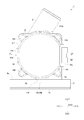
- FIG. 1 is a perspective view of a pump fixing structure 1 according to an embodiment of the present invention.
- FIG. 2 is a side view showing the fixing structure 1 of the pump shown in FIG. 1 from another direction.
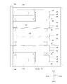
- 3 is a rear view showing the pump fixing structure 1 from the direction EE in FIG. 4 is a cross-sectional view taken along the line FF in FIG.
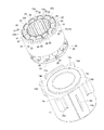
- FIG. 5 is a perspective view of the stator 12 shown in FIG.
- FIG. 6 is a side view of the state in which the stator 12 and the motor case 14 shown in FIG. 5 are integrated.
- the pump fixing structure 1 of this embodiment is a structure for fixing the pump 2 to the fixing base 3, and includes the pump 2 and the fixing base 3 to which the pump 2 is fixed.
- each of the three directions orthogonal to each other is orthogonal to the X direction and the axial direction of the motor unit 7.
- the direction parallel to the Y direction and the axis direction of the motor unit 7 and perpendicular to the upper surface portion 3a of the solid base 3 is the Z direction
- the X direction is the front-rear direction
- the Y direction is the left-right direction
- the Z direction is the up-down direction.
- the X1 direction side is the "front” side
- the X2 direction side is the “rear (rear)” side
- the Y1 direction side is the "right” side
- the Y2 direction side is the “left” side
- the Z1 direction The side is the “upper” side
- the Z2 direction side is the “lower” side.
- the pump 2 is a type of pump called a can pump, and includes a pump unit 6 in which an impeller 5a (see FIG. 4) is disposed and a motor unit 7 for rotating the impeller 5a.
- the pump portion 6 constitutes a front end side portion in the axial direction of the motor portion 7 of the pump 2
- the motor portion 7 constitutes a rear end side portion in the axial direction of the motor portion 7 of the pump 2.
- the impeller 5a constitutes a front end side portion of the blade member 5 in the axial direction.
- the pump unit 6 includes a pump case 9 in which a fluid discharge port 9a and a suction port 9b are formed.
- the discharge port 9a is formed in a cylindrical shape that protrudes in the diagonally upward left direction
- the suction port 9b is formed in a cylindrical shape that protrudes in the forward direction.
- a flange portion 9 c for fixing the motor portion 7 to the pump portion 6 and fixing the pump 2 to the fixing base 3 is formed.
- the lower end side of the flange portion 9 c is a fixed portion 9 d that is fixed to the fixing base 3.
- the inside of the pump case 9 is a part of the pump chamber 10 as shown in FIG.
- the motor unit 7 includes a rotor 11, a stator 12, a partition member 13 that defines the pump chamber 10 together with the pump case 9, and a motor case 14 that constitutes the outer peripheral surface of the motor unit 7.
- the rotor 11 is disposed on the inner peripheral side of the stator 12. That is, the motor constituting the motor unit 7 is an inner rotor type motor.
- the partition member 13 is made of a resin material. Further, the partition wall member 13 is formed in a bottomed cylindrical shape with a flange, and is disposed between the rotor 11 and the stator 12. The flange portion 13 a of the partition wall member 13 is in contact with the flange portion 9 c of the pump case 9, and the pump chamber 10 is formed by the inside of the pump case 9 and the inside of the partition wall member 13. Between the flange portion 9c and the flange portion 13a, a seal member (O-ring) 15 for ensuring the hermeticity of the pump chamber 10 is disposed.
- O-ring seal member
- the rotor 11 includes a driving magnet 16 and a cylindrical sleeve 17.
- the rear end portion of the blade member 5 is a substantially cylindrical holding portion 5b.
- the holding portion 5b constitutes a part of the rotor 11, and the driving magnet 16 is fixed to the outer peripheral surface of the holding portion 5b, and the sleeve 17 is fixed to the inner peripheral surface of the holding portion 5b.
- the rotor 11 is rotatably supported by a fixed shaft 18 fixed to the pump case 9 and the partition wall member 13 with the front-rear direction as an axial direction. Two thrust bearings 19 are attached to the fixed shaft 18 so as to sandwich the sleeve 17 in the front-rear direction.
- the rotor 11 is disposed inside the pump chamber 10.
- the stator 12 includes a drive coil 22, a stator core 23, and a bobbin 24, and is formed in a substantially cylindrical shape as a whole.
- the stator core 23 is, for example, a laminated core formed by laminating thin magnetic plates made of a magnetic material.
- the stator core 23 is a substantially cylindrical outer circumferential core portion 23a that constitutes the outer circumferential surface of the stator core 23, and a radial direction from the outer circumferential core portion 23a. And a plurality of salient pole portions 23b projecting inward (see FIG. 5).
- the width of the outer peripheral core portion 23a in the front-rear direction is equal to the width of the salient pole portion 23b in the front-rear direction.
- the bobbin 24 is formed in a cylindrical shape with a hook having hooks at both ends.
- the driving coil 22 is wound around the outer peripheral surface of the bobbin 24.
- the bobbin 24 around which the driving coil 22 is wound is inserted into the salient pole portion 23 b from the inside in the radial direction, and the driving coil 22 is wound around the salient pole portion 23 b via the bobbin 24.
- the bobbin 24 around which the driving coil 22 is wound is disposed on the inner peripheral side of the outer peripheral core portion 23a. Both ends of the driving coil 22 are entangled with terminal pins 25 fixed to the bobbin 24.
- substrates 26 and 27 having a drive circuit and a control circuit fixed to the rear surface side of the bottom portion 13b of the partition wall member 13 are arranged.
- the substrate 26 and the substrate 27 are electrically connected.
- the terminal pins 25 are electrically connected to the substrate 26 by soldering or the like.
- Various electronic components are mounted on the substrate 27.
- a connector 28 for supplying a current to the driving coil 22 is mounted on the substrate 27. In FIG. 6, illustration of the boards 26 and 27 and the connector 28 is omitted. In addition to supplying current to the driving coil 22 via the connector 28, various signals are exchanged via the connector 28.
- the motor case 14 is made of resin. Specifically, the motor case 14 is formed of BMC (Bulk Molding Compound). The motor case 14 is integrally formed with the stator 12 and the partition member 13 so as to cover the outer peripheral side and the rear surface side of the stator 12, and is formed in a substantially bottomed cylindrical shape. A mold (not shown) used when the stator 12 and the like and the motor case 14 are integrally formed is configured to be divided in the front-rear direction, and the outer peripheral surface of the motor case 14 extends from the mold to the motor case 14. It is formed in the shape of a substantially truncated cone having a draft angle for removing.
- the outer peripheral surface of the motor case 14 is used as the outer peripheral surface of the motor unit 7
- the outer peripheral surface of the motor unit 7 is formed in a substantially truncated cone shape.
- the outer peripheral surface of the motor unit 7 is formed in a substantially truncated cone shape whose outer diameter gradually decreases toward the rear end side of the motor case 14.
- the connector 28 is mounted on the substrate 27, and the substrates 26 and 27 are fixed to the partition wall member 13.
- the substrates 26 and 27 are integrated with the motor case 14 so as to be covered with the motor case 14 when the stator 12 and the like and the motor case 14 are integrally formed.
- the connector 28 is integrated with the motor case 14 so that a part of the connector 28 protrudes from the outer peripheral surface of the motor case 14 when the stator 12 and the like and the motor case 14 are integrally formed.
- a connector trace 14a On the outer peripheral side of the motor case 14, a connector trace 14a, a gate trace 14b, which is a trace of a mold gate used when the stator 12 or the like and the motor case 14 are integrally molded, is formed.
- the forming portion 14c is formed so as to protrude outward in the radial direction.
- four screw protrusions 14 d for fixing the motor unit 7 to the pump unit 6 are formed on the outer peripheral surface of the motor case 14 so as to protrude outward in the radial direction from the outer peripheral surface of the motor unit 7. ing.
- the connector placement portion 14a protrudes leftward from the outer peripheral surface of the motor portion 7.
- the gate mark forming portion 14c protrudes in the right direction. That is, when viewed from the front-rear direction, which is the axial direction of the motor unit 7, as shown in FIG. 3, the gate mark 14b is formed on the opposite side of the connector arrangement unit 14a across the axis center of the motor unit 7. A gate mark forming portion 14c is formed.
- the shape of the motor case 14 when viewed from the axial direction of the motor unit 7 is symmetrical with respect to a line parallel to the horizontal direction connecting the center of the connector 28 and the center of the gate mark 14b. .
- the connector placement portion 14a and the gate trace forming portion 14c are formed in almost the entire area of the motor case 14 in the front-rear direction. Further, the left side surface of the connector placement portion 14a and the right side surface of the gate trace forming portion 14c are substantially parallel to a ZX plane constituted by the Z direction and the X direction.
- the gate trace 14b is formed so as to slightly protrude in the right direction from the right side surface (surface) of the gate trace forming portion 14c.
- the gate trace 14b is formed at the center position in the vertical direction on the right side surface of the gate trace formation portion 14c, and is formed in a predetermined range in the front-rear direction on the right side surface of the gate trace formation portion 14c.
- a part of the gate trace 14b overlaps with the outer core portion 23a when viewed from the left-right direction. That is, in the radial direction of the motor part 7, a part of the gate mark 14b overlaps with the outer peripheral core part 23a. Specifically, in the radial direction of the motor portion 7, a part of the front end side of the gate mark 14b overlaps with the outer core portion 23a.
- the four screw protrusions 14d are formed so that the outer peripheral surface of the motor part 7 protrudes in the upper right direction, the lower right direction, the upper left direction, and the lower left direction.
- a screw hole 14e into which the screw 30 is engaged is formed in the screw protrusion 14d.
- the motor unit 7 is fixed to the pump unit 6 by four screws 30.
- the fixed base 3 is formed by bending a single metal plate made of a steel plate or the like.
- the fixed base 3 has the pump 2 mounted from a pair of opposite sides of an upper surface portion 3a having a flat surface as a motor support portion formed in a substantially rectangular shape and an upper surface portion 3a disposed on both sides in the front-rear direction.
- a side surface portion 3b formed to bend downward in the opposite direction to the placed direction, and a bottom surface portion 3c formed to be bent outward from the lower end of the side surface portion 3b in the front-rear direction.
- the bottom surface portion 3c is fixed to a frame or the like of a predetermined device in which the pump 2 is used.
- the fixed portion 9d of the pump case 9 positioned below the outer peripheral surface of the motor portion 7 is fixed to the side surface portion 3b disposed on the front side of the two side surface portions 3b by screws 31.
- the fixed portion 9d is located below the outer peripheral surface of the motor case 14, and the fixed portion 9d is fixed to the side surface portion 3b with the outer peripheral surface of the motor portion 7 facing the upper surface portion 3a.
- a gap is formed between them.
- the upper surface portion 3 a is disposed on the lower side of the motor portion 7.
- a buffer member 34 is disposed between the lower end of the motor unit 7 and the upper surface of the upper surface portion 3a.
- the motor portion 7 provided in a portion where the connector placement portion 14a, the gate mark 14b, the gate mark forming portion 14c, and the screw protrusion portion 14d that protrude radially outward from the cylindrical outer peripheral surface of the motor portion 7 are not formed.
- 14f and the flat surface of the upper surface portion 3a are arranged to face each other, and a buffer member 34 is disposed between the contact portion 14f of the motor unit 7 and the upper surface portion 3a. ing.
- the connector arrangement portion 14a, the gate mark 14b, the gate mark forming portion 14c, and the screw protrusion portion 14d protruding from the outer peripheral surface of the motor unit 7 It is provided at a position where it does not contact the upper surface portion 3a.
- the contact portion 14f formed of a flat outer peripheral surface of the motor portion 7 and the buffer member 34 are disposed so as to face each other, so that the motor portion 7 and the fixing base 3 can be disposed close to each other. ing.
- the discharge port 9a is provided so as to protrude upward from the outer peripheral surface of the motor unit 7, and the contact portion 14f is provided on the lower outer peripheral surface of the motor unit 7, so that the fixed portion Since 9d protrudes downward from the outer peripheral surface of the motor portion 7, the height of the pump 2 fixed to the fixed base 3 can be made low, which is suitable for downsizing.
- a buffer member 35 as a second buffer member is disposed between the front surface of the side surface portion 3b disposed on the front side and the rear surface of the fixed portion 9d.
- the buffer member 34 is formed of an elastic material having elasticity.
- the buffer member 34 of this embodiment is a rubber bush made of rubber, for example.
- the buffer member 34 includes a large-diameter portion 34a formed in a columnar shape, and a small-diameter portion 34b as an engaging protrusion formed in a columnar shape having an outer diameter smaller than that of the large-diameter portion 34a. It is formed in a cylindrical shape with a mark.
- the small diameter portion 34b is engaged with a circular engagement hole formed in the upper surface portion 3a of the fixed base 3, and the large diameter portion 34a is disposed on the upper surface side of the upper surface portion 3a. As shown in FIG. 2, a gap is formed between the motor portion 7 and the upper surface portion 3a.
- the lower end of the motor part 7 and the upper surface of the large diameter part 34a are contacting, and the upper surface of the upper surface part 3a and the lower surface of the large diameter part 34a are contacting.
- the engagement hole formed in the upper surface portion 3a passes through the upper surface portion 3a, and the lower end side of the small diameter portion 34b protrudes below the lower surface of the upper surface portion 3a.
- the buffer member 35 is formed of an elastic material having elasticity.
- the buffer member 35 of this embodiment is a rubber plate made of rubber, for example, and is formed in a flat plate shape.
- the buffer member 35 is fixed between the fixed portion 9d and the side surface portion 3b by a screw 31 while being sandwiched between the fixed portion 9d and the side surface portion 3b.
- the buffer member 34 is disposed between the upper surface portion 3 a of the fixed base 3 and the motor portion 7. Therefore, in this embodiment, it is possible to suppress the vibration from the motor unit 7 to the upper surface part 3a by the buffer member 34. Further, in this embodiment, since the buffer member 35 is disposed between the side surface portion 3 b of the fixing base 3 and the fixed portion 9 d of the pump case 9, the vibration of the motor portion 7 is transmitted through the pump portion 6 to the side surface portion. Transmission to 3b can be suppressed by the buffer member 35.
- the buffer member 34 since the buffer member 34 is disposed between the upper surface portion 3a and the motor portion 7, the fixed portion 9d of the pump case 9 fixed to the side surface portion 3b of the fixing base 3 is aged. Even if it deform
- the small diameter portion 34b of the buffer member 34 is engaged with an engagement hole formed in the upper surface portion 3a. Therefore, in this embodiment, it is possible to prevent the displacement of the buffer member 34 with respect to the upper surface portion 3a.
- the gate mark forming part 14c when viewed from the front-rear direction, which is the axial direction of the motor unit 7, the gate mark forming part 14c is formed on the opposite side of the connector placement part 14a across the axis center of the motor part 7.
- the shape of the motor case 14 when viewed from the axial direction of the motor unit 7 is symmetrical with respect to a line parallel to the left-right direction connecting the center of the connector 28 and the center of the gate mark 14b. ing. Therefore, in this embodiment, when the stator 12 and the like and the motor case 14 are integrally formed, the resin easily flows from the gate of the mold toward the portion where the connector 28 is disposed.
- the gate trace forming portion 14c is formed so as to protrude outward in the radial direction of the motor portion 7, and the thickness of the gate trace forming portion 14c is such that the connector placement portion 14a and the screw protruding portion 14d are formed. It is thicker than other portions of the motor case 14 except for. For this reason, in this embodiment, the resin easily enters the mold from the gate when the stator 12 and the like and the motor case 14 are integrally formed.
- a part of the gate mark 14b overlaps the outer core part 23a in the radial direction of the motor part 7. Therefore, it becomes difficult for the injection pressure of the resin to be directly applied to the drive coil 22 and the like when the stator 12 and the motor case 14 are integrally formed. Therefore, in this embodiment, it is possible to prevent damage to the drive coil 22 and the like when the stator 12 and the motor case 14 are integrally formed.
- the motor case 14 is formed of BMC. Therefore, in this embodiment, it is possible to improve the heat dissipation and vibration absorption of the motor case 14.
- the buffer member 34 is formed in a stepped columnar shape including a large diameter portion 34a and a small diameter portion 34b.
- the buffer member 34 may be formed in a columnar shape including only the large diameter portion 34a, or may be formed in a flat plate shape or a block shape.
- the buffer member 34 is fixed to the upper surface of the upper surface portion 3a of the fixing base 3 by adhesion or the like.
- the buffer member 35 is disposed between the side surface portion 3b of the fixing base 3 and the fixed portion 9d of the pump case 9. In addition to this, for example, if the vibration of the motor unit 7 is not easily transmitted to the side surface part 3b via the pump unit 6, the buffer member 35 is not disposed between the side surface part 3b and the fixed part 9d. good.
- the motor case 14 is formed of BMC, but the motor case 14 may be formed of a resin other than BMC.
- the gate mark 14b is formed on the opposite side of the connector arrangement portion 14a across the axis center of the motor unit 7 when viewed from the front-rear direction which is the axial direction of the motor unit 7.
- the gate trace 14b may be formed at any other position.
- a part of gate trace 14b has overlapped with the outer periphery core part 23a.
- the entire gate mark 14 b may overlap the outer core portion 23 a. In this case, it is possible to effectively prevent damage to the drive coil 22 and the like when the stator 12 and the motor case 14 are integrally formed.
- the gate mark 14b and the outer core part 23a may not overlap each other.
Abstract
ポンプ部とモータ部とを有するポンプを固定台に固定するためのポンプの固定構造において、固定台に固定されるポンプ部の被固定部が経年変化で変形しても、モータ部から固定台への振動の伝達を抑制することが可能なポンプの固定構造を提供する。ポンプの固定構造1では、ポンプ2は、内部に羽根車が配置されるポンプ部6と、羽根車を回転させるためのモータ部7とを備え、モータ部7は、樹脂で形成されるとともにステータと一体成形されるモータケース14を備え、モータ部7の外周面は、ステータとモータケース14との一体成形時に使用される金型からモータケース14を抜くための抜き勾配を有する略円錐台面状に形成されている。固定台3は、モータ部7の下側に配置されるモータ支持部3aを備え、固定台3には、ポンプ部6の被固定部9dが固定されている。モータ部7とモータ支持部3aとの間には緩衝部材34が配置されている。
Description
本発明は、ポンプを固定台に固定するためのポンプの固定構造に関する。また、本発明は、かかるポンプの固定構造を構成するポンプに関する。
従来、ポンプを台に固定するためのポンプの固定装置が知られている(たとえば、特許文献1参照)。特許文献1では、ポンプは、当て部を介して台に固定されている。また、ポンプは、流体の吐出口と流入口とを有するポンプ部と、ポンプ部の内部に配置される羽根車を回転させるためのモータ部とを備えている。モータ部の外周面は、円柱面状に形成されている。当て部および台は、金属板を所定形状に折り曲げることで形成されている。また、当て部は、円柱面状に形成されるモータ部の外周面が固定される円弧状の曲面部と、曲面部の両端から下方向へ折れ曲がる側面部と、側面部の下端から水平方向へ伸びる底面部とから構成されている。台は、当て部の底面部が固定される上面部と、上面部の両端から下方向へ折れ曲がる側面部とから構成されている。
また、従来、流体の吐出口と流入口とを有するポンプ部と、ポンプ部の内部に配置される羽根車を回転させるためのモータ部とを備えるポンプとして、モータ部を構成するステータと、ステータを覆う樹脂製のモールド部とを備えるポンプが知られている(たとえば、特許文献2参照)。特許文献2に記載のポンプでは、モールド部は、ステータと一体成形されており、モータ部の外周面を構成している。特許文献2に記載のポンプのように、ステータと一体成形されるモールド部を有するポンプでは、モータ部の外周面は、一般に、ステータとモールド部との一体成形時に使用される金型からモールド部を抜くための抜き勾配を有する円錐台面状に形成されている。
特許文献1に記載のポンプでは、モータ部を構成するロータが回転するため、モータ部において振動が発生しやすい。一方で、このポンプでは、金属板で形成された当て部の曲面部にモータ部の外周面が固定され、当て部の底面部が台に固定されているため、モータ部で発生する振動が当て部を介して台に伝わりやすい。したがって、モータ部から台への振動の伝達を抑制するためには、台の上面部とモータ部との間に隙間をあけるとともに、たとえば、台の側面部にポンプ部を固定することが好ましい。しかしながら、この場合であっても、台の側面部に固定されるポンプ部の被固定部が経年変化によって変形すると、台の上面部とモータ部とが接触して、モータ部の振動が台へ伝達されるおそれがある。
そこで、本発明の課題は、ポンプ部とモータ部とを有するポンプを固定台に固定するためのポンプの固定構造において、固定台に固定されるポンプ部の被固定部が経年変化で変形しても、モータ部から固定台への振動の伝達を抑制することが可能なポンプの固定構造を提供することにある。また、本発明の課題は、かかるポンプの固定構造を構成するポンプを提供することにある。
上記の課題を解決するため、本発明のポンプの固定構造は、ポンプを固定台に固定するためのポンプの固定構造において、ポンプは、流体の吐出口と吸入口とを有し内部に羽根車が配置されるポンプ部と、羽根車を回転させるためのモータ部とを備え、モータ部は、駆動用コイルと駆動用コイルが巻回されるステータコアとを有するステータと、樹脂で形成されるとともにステータと一体成形されモータ部の外周面を構成するモータケースとを備え、モータ部の外周面は、ステータとモータケースとの一体成形時に使用される金型からモータケースを抜くための抜き勾配を有する略円錐台面状に形成され、ポンプ部は、固定台に固定される被固定部を備え、固定台は、金属板を折り曲げることで形成されるとともにモータ部の下側に配置されるモータ支持部を備え、モータ部とモータ支持部との間には、弾性を有する緩衝部材が配置されていることを特徴とする。
本発明のポンプの固定構造では、モータ部の下側に配置されるモータ支持部とモータ部との間に、弾性を有する緩衝部材が配置されている。そのため、本発明では、固定台に固定されるポンプ部の被固定部が経年変化で変形しても、固定台のモータ支持部にモータ部が接触するのを防止することが可能になる。したがって、本発明では、固定台に固定されるポンプ部の被固定部が経年変化で変形しても、モータ部から固定台への振動の伝達を抑制することが可能になる。
また、本発明のポンプの固定構造では、モータ部の下側に配置されるモータ支持部とモータ部との間に緩衝部材が配置されているため、モータ部の外周面が抜き勾配を有する略円錐台面状に形成されていても、緩衝部材によって、モータ部を安定した状態で支持することが可能になる。
本発明において、たとえば、固定台は、略矩形状に形成されるモータ支持部と、略矩形状に形成されるモータ支持部の1組の対辺のそれぞれから下方向へ折れ曲がる側面部とを有する略角溝状に形成され、被固定部は、2個の側面部のうちの一方の側面部に固定され、モータ部とモータ支持部との間には隙間が形成され、モータ部およびモータ支持部と緩衝部材とが接触している。この場合、側面部と被固定部との間には、弾性を有する第2の緩衝部材が配置されていることが好ましい。このように構成すると、モータ部の振動がポンプ部を介して固定台に伝達されるのを第2の緩衝部材によって抑制することが可能になる。
本発明において、モータ支持部には、緩衝部材の一部が係合する係合孔が形成され、緩衝部材には、係合孔に係合する係合突起が形成されていることが好ましい。このように構成すると、モータ支持部に対する緩衝部材の位置ずれを防止することが可能になる。
本発明のポンプの固定構造を構成するポンプでは、モータ部は、駆動用コイルに電流を供給するためのコネクタを備え、コネクタは、ステータとモータケースとの一体成形時にモータケースの外周面から突出するようにモータケースと一体化され、モータ部の軸方向から見たときに、モータケースの、モータ部の軸中心を挟んだコネクタの反対側に、金型のゲートの跡であるゲート跡が形成されていることが好ましい。この場合には、モータ部の軸方向から見たときのモータケースの形状を、コネクタの中心とゲート跡とを結ぶ線に対して線対称とすることが可能になる。したがって、ステータとモータケースとの一体成形時にゲートからコネクタが配置される部分に向かって均等に樹脂が流れやすくなる。
本発明において、モータケースには、ゲート跡が表面に形成されるゲート跡形成部がモータ部の径方向の外側へ突出するように形成されていることが好ましい。このように構成すると、ゲート跡形成部の肉厚を他の部分よりも厚くすることが可能になるため、ステータとモータケースとの一体成形時にゲートから金型の内部へ樹脂が入り込みやすくなる。
本発明のポンプの固定構造を構成するポンプでは、モータケースは、BMC(Bulk Molding Compound)で形成されていることが好ましい。この場合には、モータケースの放熱性および吸振性を高めることが可能になる。
本発明のポンプの固定構造を構成するポンプでは、モータ部は、ステータの内周側に配置されるロータを備え、ステータコアは、駆動用コイルの外周側に配置される略円筒状の外周コア部を備え、モータ部の径方向において、金型のゲートの跡であるゲート跡の少なくとも一部と、外周コア部の少なくとも一部とが重なっていることが好ましい。この場合には、ステータとモータケースとの一体成形時の樹脂の射出圧力が駆動用コイル等に直接かかりにくくなる。したがって、ステータとモータケースとの一体成形時の駆動用コイル等の損傷を防止することが可能になる。
以上のように、本発明のポンプの固定構造では、固定台に固定されるポンプ部の被固定部が経年変化で変形しても、モータ部から固定台への振動の伝達を抑制することが可能になる。また、本発明のポンプでは、ステータとモータケースとの一体成形時にゲートからコネクタが配置される部分に向かって均等に樹脂が流れやすくなる等の効果を得ることができる。
以下、図面を参照しながら、本発明の実施の形態を説明する。
(ポンプの固定構造の構成)
図1は、本発明の実施の形態にかかるポンプの固定構造1の斜視図である。図2は、図1に示すポンプの固定構造1を別の方向から示す側面図である。図3は、図2のE-E方向からポンプの固定構造1を示す背面図である。図4は、図3のF-F断面の断面図である。図5は、図4に示すステータ12をモータケース14から取り出した状態の斜視図である。図6は、図5に示すステータ12とモータケース14とが一体化された状態の側面図である。
図1は、本発明の実施の形態にかかるポンプの固定構造1の斜視図である。図2は、図1に示すポンプの固定構造1を別の方向から示す側面図である。図3は、図2のE-E方向からポンプの固定構造1を示す背面図である。図4は、図3のF-F断面の断面図である。図5は、図4に示すステータ12をモータケース14から取り出した状態の斜視図である。図6は、図5に示すステータ12とモータケース14とが一体化された状態の側面図である。
本形態のポンプの固定構造1は、ポンプ2を固定台3に固定するための構造であり、ポンプ2と、ポンプ2が固定される固定台3とを備えている。以下の説明では、図2、図3等に示すように、互いに直交する3方向のそれぞれをモータ部7の軸線方向をX方向、モータ部7の軸線方向と直行し固定台3の上面部3aと平行な方向をY方向およびモータ部7の軸線方向と直交し固体台3の上面部3aと直交する方向をZ方向とし、X方向を前後方向、Y方向を左右方向、Z方向を上下方向とする。また、図2、図3等のX1方向側を「前」側、X2方向側を「後(後ろ)」側、Y1方向側を「右」側、Y2方向側を「左」側、Z1方向側を「上」側、Z2方向側を「下」側とする。
ポンプ2は、キャンドポンプと呼ばれるタイプのポンプであり、羽根車5a(図4参照)が内部に配置されるポンプ部6と、羽根車5aを回転させるためのモータ部7とを備えている。ポンプ部6は、ポンプ2のモータ部7の軸線方向の前端側部分を構成し、モータ部7は、ポンプ2のモータ部7の軸線方向の後端側部分を構成している。羽根車5aは、羽根部材5の軸線方向の前端側部分を構成している。
ポンプ部6は、流体の吐出口9aと吸入口9bとが形成されるポンプケース9を備えている。吐出口9aは、左斜め上方向に向かって突出する円筒状に形成され、吸入口9bは、前方向に向かって突出する円筒状に形成されている。ポンプケース9の後端側には、ポンプ部6にモータ部7を固定するとともに、ポンプ2を固定台3に固定するためのフランジ部9cが形成されている。フランジ部9cの下端側は、固定台3に固定される被固定部9dとなっている。ポンプケース9の内部は、図4に示すように、ポンプ室10の一部となっている。
モータ部7は、ロータ11と、ステータ12と、ポンプケース9とともにポンプ室10を画定する隔壁部材13と、モータ部7の外周面を構成するモータケース14とを備えている。ロータ11は、ステータ12の内周側に配置されている。すなわち、モータ部7を構成するモータは、インナーロータ型のモータである。
隔壁部材13は、樹脂材料で形成されている。また、隔壁部材13は、鍔付きの有底円筒状に形成されており、ロータ11とステータ12との間に配置されている。隔壁部材13の鍔部13aは、ポンプケース9のフランジ部9cに当接しており、ポンプケース9の内部と隔壁部材13の内部とによってポンプ室10が形成されている。フランジ部9cと鍔部13aとの間には、ポンプ室10の密閉性を確保するためのシール部材(Oリング)15が配置されている。
ロータ11は、駆動用磁石16と、円筒状のスリーブ17とを備えている。羽根部材5の後端側部分は、略円筒状の保持部5bとなっている。保持部5bは、ロータ11の一部を構成しており、保持部5bの外周面に駆動用磁石16が固定され、保持部5bの内周面にスリーブ17が固定されている。ロータ11は、前後方向を軸方向としてポンプケース9および隔壁部材13に固定される固定軸18に回転可能に支持されている。固定軸18には、前後方向でスリーブ17を挟むように2個のスラスト軸受19が取り付けられている。ロータ11は、ポンプ室10の内部に配置されている。
ステータ12は、駆動用コイル22と、ステータコア23と、ボビン24とを備えており、全体として略円筒状に形成されている。ステータコア23は、たとえば、磁性材料からなる薄い磁性板が積層されて形成された積層コアであり、ステータコア23の外周面を構成する略円筒状の外周コア部23aと、外周コア部23aから径方向の内側へ突出する複数の突極部23bとを備えている(図5参照)。前後方向における外周コア部23aの幅と、前後方向における突極部23bの幅とは等しくなっている。
ボビン24は、両端に鍔部を有する鍔付きの円筒状に形成されている。駆動用コイル22は、ボビン24の外周面に巻回されている。駆動用コイル22が巻回されたボビン24は、径方向の内側から突極部23bに挿通されており、駆動用コイル22はボビン24を介して突極部23bに巻回されている。また、駆動用コイル22が巻回されたボビン24は、外周コア部23aの内周側に配置されている。駆動用コイル22の両端部は、ボビン24に固定される端子ピン25に絡げられている。
ステータ12の後端側には、隔壁部材13の底部13bの後面側に固定される駆動回路や制御回路を備えた基板26、27が配置されている。基板26と基板27とは、電気的に接続されている。基板26には、端子ピン25が半田付け等されて電気的に接続されている。基板27には、各種の電子部品が実装されている。また、基板27には、駆動用コイル22に電流を供給するためのコネクタ28が実装されている。なお、図6では、基板26、27およびコネクタ28の図示を省略している。また、コネクタ28を介して駆動用コイル22への電流の供給が行われる他に、コネクタ28を介して各種の信号のやりとり等が行われる。
モータケース14は、樹脂で形成されている。具体的には、モータケース14は、BMC(Bulk Molding Compound)で形成されている。また、モータケース14は、ステータ12の外周側および後面側を覆うように、ステータ12および隔壁部材13と一体成形されており、略有底円筒状に形成されている。ステータ12等とモータケース14との一体成形時に使用される金型(図示省略)は、前後方向に分割されるように構成されており、モータケース14の外周面は、金型からモータケース14を抜くための抜き勾配を有する略円錐台面状に形成されている。すなわち、モータケース14の外周面をモータ部7の外周面としているので、モータ部7の外周面は、略円錐台面状に形成されている。具体的には、モータ部7の外周面は、モータケース14の後端側に向かうにしたがってその外径がしだいに小さくなる略円錐台面状に形成されている。
なお、ステータ12等とモータケース14との一体成形時には、コネクタ28は基板27に実装され、基板26、27は隔壁部材13に固定されている。基板26、27は、ステータ12等とモータケース14との一体成形時に、モータケース14に覆われるようにモータケース14と一体化される。また、コネクタ28は、ステータ12等とモータケース14との一体成形時に、その一部がモータケース14の外周面から突出するようにモータケース14と一体化される。
モータケース14の外周側には、コネクタ28がコネクタ配置部14aと、ステータ12等とモータケース14との一体成形時に使用される金型のゲートの跡であるゲート跡14bが形成されるゲート跡形成部14cとが径方向の外側へ突出するように形成されている。また、モータケース14の外周面には、ポンプ部6にモータ部7を固定するための4個のネジ用突出部14dがモータ部7の外周面から径方向の外側へ突出するように形成されている。
コネクタ配置部14aは、モータ部7の外周面から左方向へ突出している。一方、ゲート跡形成部14cは、右方向へ突出している。すなわち、モータ部7の軸線方向となる前後方向から見たときに、図3に示すように、モータ部7の軸中心を挟んだコネクタ配置部14aの反対側に、ゲート跡14bが形成されるゲート跡形成部14cが形成されている。本形態では、モータ部7の軸方向から見たときのモータケース14の形状は、コネクタ28の中心とゲート跡14bの中心とを結ぶ左右方向に平行な線に対して線対称となっている。コネクタ配置部14aおよびゲート跡形成部14cは、前後方向におけるモータケース14のほぼ全域に形成されている。また、コネクタ配置部14aの左側面、および、ゲート跡形成部14cの右側面は、Z方向とX方向とから構成されるZX平面と略平行になっている。
ゲート跡14bは、ゲート跡形成部14cの右側面(表面)から右方向へわずかに突出するように形成されている。また、ゲート跡14bは、ゲート跡形成部14cの右側面の、上下方向における中心位置に形成されるとともに、ゲート跡形成部14cの右側面の、前後方向における所定の範囲に形成されている。図6に示すように、ゲート跡14bの一部は、左右方向から見たときに、外周コア部23aと重なっている。すなわち、モータ部7の径方向において、ゲート跡14bの一部は、外周コア部23aと重なっている。具体的には、モータ部7の径方向において、ゲート跡14bの前端側の一部が外周コア部23aと重なっている。
4個のネジ用突出部14dは、モータ部7の外周面がら右斜め上方向、右斜め下方向、左斜め上方向および左斜め下方向のそれぞれに向かって突出するように形成されている。ネジ用突出部14dには、ネジ30が係合するネジ孔14eが形成されている。モータ部7は、4本のネジ30によって、ポンプ部6に固定されている。
固定台3は、鋼板等からなる1枚の金属板を折り曲げることで形成されている。また、固定台3は、略矩形状に形成されるモータ支持部としての平坦な面を備える上面部3aと、前後方向の両側に配置される上面部3aの1組の対辺からポンプ2が載置されている方向に対して反対側の下方向へ折れ曲がるように形成される側面部3bと、側面部3bの下端から前後方向の外方向へ折れ曲がるように形成され、フランジを形成する底面部3cとから構成されており、上面部3aを底面とし、側面部3bを壁面とした略四角溝状に形成されている。底面部3cは、ポンプ2が使用される所定の装置のフレーム等に固定される。
2個の側面部3bのうちの前側に配置される側面部3bには、ネジ31によって、モータ部7の外周面より下側に位置するポンプケース9の被固定部9dが固定されている。被固定部9dは、モータケース14の外周面より下側に位置しており、側面部3bに被固定部9dが固定された状態で、上面部3aと対向するモータ部7の外周面との間に隙間が形成されている。上面部3aは、モータ部7の下側に配置されている。モータ部7の下端と上面部3aの上面との間には、緩衝部材34が配置されている。すなわち、モータ部7の円柱状の外周面から半径方向外側に突出したコネクタ配置部14a、ゲート跡14b、ゲート跡形成部14c及びネジ用突出部14dが形成されていない部分に設けたモータ部7の下端に設けた当接部14fと、上面部3aの平坦な面が対向して配置されるとともに、モータ部7の当接部14fと上面部3aとの間には緩衝部材34が配置されている。当接部14fと緩衝部材34が当接した状態で、モータ部7の外周面から突出したコネクタ配置部14a、ゲート跡14b、ゲート跡形成部14c及びネジ用突出部14dは、緩衝部材34及び上面部3aとは、接触しない位置に設けられている。このようにモータ部7の平坦な外周面からなる当接部14fと緩衝部材34を対向して配置しているのでモータ部7と固定台3を近接して配置できるので装置の小型化に適している。更に、本実施例では、吐出口9aはモータ部7の外周面より上側に向かって突出して設けてあり、当接部14fはモータ部7の下側の外周面の設けてあり、被固定部9dはモータ部7の外周面より下側に向かって突出して設けてあるので、固定台3に固定されたポンプ2の高さを低く構成できるので小型化に適している。また、前側に配置される側面部3bの前面と被固定部9dの後面との間には、第2の緩衝部材としての緩衝部材35が配置されている。
緩衝部材34は、弾性を有する弾性材料で形成されている。本形態の緩衝部材34は、たとえば、ゴムで形成されたゴムブッシュである。この緩衝部材34は、円柱状に形成される大径部34aと、大径部34aよりも外径の小さな円柱状に形成される係合突起としての小径部34bとから構成されており、段付きの円柱状に形成されている。小径部34bは、固定台3の上面部3aに形成される円形の係合孔に係合しており、大径部34aは、上面部3aの上面側に配置されている。図2に示すように、モータ部7と上面部3aとの間には隙間が形成されている。また、モータ部7の下端と大径部34aの上面とが接触し、上面部3aの上面と大径部34aの下面とが接触している。なお、上面部3aに形成される係合孔は、上面部3aを貫通しており、小径部34bの下端側は、上面部3aの下面よりも下側へ突出している。
緩衝部材35は、弾性を有する弾性材料で形成されている。本形態の緩衝部材35は、たとえば、ゴムで形成されたゴム板であり、平板状に形成されている。この緩衝部材35は、被固定部9dと側面部3bとの間に挟まれた状態で、ネジ31によって、被固定部9dと側面部3bとの間に固定されている。
(本形態の主な効果)
以上説明したように、本形態では、固定台3の上面部3aとモータ部7との間に緩衝部材34が配置されている。そのため、本形態では、モータ部7から上面部3aへ振動が伝達されるのを緩衝部材34によって抑制することが可能になる。また、本形態では、固定台3の側面部3bとポンプケース9の被固定部9dとの間に緩衝部材35が配置されているため、モータ部7の振動がポンプ部6を介して側面部3bに伝達されるのを緩衝部材35によって抑制することが可能になる。
以上説明したように、本形態では、固定台3の上面部3aとモータ部7との間に緩衝部材34が配置されている。そのため、本形態では、モータ部7から上面部3aへ振動が伝達されるのを緩衝部材34によって抑制することが可能になる。また、本形態では、固定台3の側面部3bとポンプケース9の被固定部9dとの間に緩衝部材35が配置されているため、モータ部7の振動がポンプ部6を介して側面部3bに伝達されるのを緩衝部材35によって抑制することが可能になる。
また、本形態では、上面部3aとモータ部7との間に緩衝部材34が配置されているため、固定台3の側面部3bに固定されるポンプケース9の被固定部9dが経年変化で変形しても、上面部3aにモータ部7が接触するのを防止することができる。したがって、本形態では、被固定部9dが経年変化で変形しても、モータ部7から固定台3への振動の伝達を抑制することが可能になる。さらに、本形態では、上面部3aとモータ部7との間に緩衝部材34が配置されているため、モータ部7の外周面が抜き勾配を有する略円錐台面状に形成されていても、緩衝部材34によって、モータ部7を安定した状態で支持することが可能になる。
本形態では、緩衝部材34の小径部34bは、上面部3aに形成される係合孔に係合している。そのため、本形態では、上面部3aに対する緩衝部材34の位置ずれを防止することが可能になる。
本形態では、モータ部7の軸方向となる前後方向から見たときに、モータ部7の軸中心を挟んだコネクタ配置部14aの反対側に、ゲート跡14bが形成されるゲート跡形成部14cが形成されており、モータ部7の軸線方向から見たときのモータケース14の形状は、コネクタ28の中心とゲート跡14bの中心とを結ぶ左右方向に平行な線に対して線対称となっている。そのため、本形態では、ステータ12等とモータケース14との一体成形時に、金型のゲートからコネクタ28が配置される部分に向かって均等に樹脂が流れやすくなる。また、本形態では、ゲート跡形成部14cがモータ部7の径方向の外側へ突出するように形成されており、ゲート跡形成部14cの肉厚は、コネクタ配置部14aおよびネジ用突出部14dを除くモータケース14の他の部分よりも厚くなっている。そのため、本形態では、ステータ12等とモータケース14との一体成形時にゲートから金型の内部へ樹脂が入り込みやすくなる。
本形態では、モータ部7の径方向において、ゲート跡14bの一部は、外周コア部23aと重なっている。そのため、ステータ12等とモータケース14との一体成形時に樹脂の射出圧力が駆動用コイル22等に直接かかりにくくなる。したがって、本形態では、ステータ12等とモータケース14との一体成形時の駆動用コイル22等の損傷を防止することが可能になる。
本形態では、モータケース14は、BMCで形成されている。そのため、本形態では、モータケース14の放熱性および吸振性を高めることが可能になる。
(他の実施の形態)
上述した形態は、本発明の好適な形態の一例ではあるが、これに限定されるものではなく本発明の要旨を変更しない範囲において種々変形実施が可能である。
上述した形態は、本発明の好適な形態の一例ではあるが、これに限定されるものではなく本発明の要旨を変更しない範囲において種々変形実施が可能である。
上述した形態では、緩衝部材34は、大径部34aと小径部34bとからなる段付きの円柱状に形成されている。この他にもたとえば、緩衝部材34は、大径部34aのみからなる円柱状に形成されても良いし、平板状あるいはブロック状に形成されても良い。この場合には、たとえば、固定台3の上面部3aの上面に接着等によって緩衝部材34が固定される。
上述した形態では、固定台3の側面部3bとポンプケース9の被固定部9dとの間に緩衝部材35が配置されている。この他にもたとえば、モータ部7の振動がポンプ部6を介して側面部3bに伝達されにくいのであれば、側面部3bと被固定部9dとの間に緩衝部材35が配置されなくても良い。
上述した形態では、モータケース14は、BMCで形成されているが、モータケース14は、BMC以外の樹脂で形成されても良い。また、上述した形態では、モータ部7の軸方向となる前後方向から見たときに、モータ部7の軸中心を挟んだコネクタ配置部14aの反対側にゲート跡14bが形成されているが、ゲート跡14bはその他の任意の位置に形成されても良い。
上述した形態では、モータ部7の径方向において、ゲート跡14bの一部は、外周コア部23aと重なっている。この他にもたとえば、モータ部7の径方向において、ゲート跡14bの全部が外周コア部23aと重なっていても良い。この場合には、ステータ12等とモータケース14との一体成形時の駆動用コイル22等の損傷を効果的に防止することが可能になる。なお、モータ部7の径方向において、ゲート跡14bと外周コア部23aとが重なっていなくても良い。
1 ポンプの固定構造
2 ポンプ
3 固定台
5 羽根部材
6 ポンプ部
7 モータ部
9 ポンプケース
X モータ部の軸方向
10 ポンプ室
11 ロータ
12 ステータ
13 隔壁部材
14 モータケース
16 駆動用磁石
17 スリーブ
18 固定軸
19 スラスト軸受
22 駆動用コイル
23 ステータコア
24 ボビン
26 基板
27 基板
28 コネクタ
34 緩衝部材
35 緩衝部材(第2の緩衝部材)
3a 上面部(モータ支持部)
3b 側面部
3c 底面部
5a 羽根車
9a 吐出口
9b 吸入口
9d 被固定部
13a 鍔部
13b 底部
14b ゲート跡
14c ゲート跡形成部
14d ネジ用突出部
23a 外周コア部
23b 突極部
34a 大径部
34b 小径部(係合突起)
Claims (8)
- ポンプを固定台に固定するためのポンプの固定構造において、
前記ポンプは、流体の吐出口と吸入口とを有し内部に羽根車が配置されるポンプ部と、前記羽根車を回転させるためのモータ部とを備え、
前記モータ部は、駆動用コイルと前記駆動用コイルが巻回されるステータコアとを有するステータと、樹脂で形成されるとともに前記ステータと一体成形され前記モータ部の外周面を構成するモータケースとを備え、
前記モータ部の外周面は、前記ステータと前記モータケースとの一体成形時に使用される金型から前記モータケースを抜くための抜き勾配を有する略円錐台面状に形成され、
前記ポンプ部は、前記固定台に固定される被固定部を備え、
前記固定台は、金属板を折り曲げることで形成されるとともに前記モータ部の下側に配置されるモータ支持部を備え、
前記モータ部と前記モータ支持部との間には、弾性を有する緩衝部材が配置されていることを特徴とするポンプの固定構造。 - 前記固定台は、略矩形状に形成される前記モータ支持部と、略矩形状に形成される前記モータ支持部の1組の対辺のそれぞれから下方向へ折れ曲がる側面部とを有する略角溝状に形成され、
前記被固定部は、2個の前記側面部のうちの一方の前記側面部に固定され、
前記モータ部と前記モータ支持部との間には隙間が形成され、前記モータ部および前記モータ支持部と前記緩衝部材とが接触していることを特徴とする請求項1記載のポンプの固定構造。 - 前記側面部と前記被固定部との間には、弾性を有する第2の緩衝部材が配置されていることを特徴とする請求項2記載のポンプの固定構造。
- 前記モータ支持部には、前記緩衝部材の一部が係合する係合孔が形成され、
前記緩衝部材には、前記係合孔に係合する係合突起が形成されていることを特徴とする請求項3記載のポンプの固定構造。 - 請求項1記載のポンプの固定構造を構成する前記ポンプであって、
前記モータ部は、前記駆動用コイルに電流を供給するためのコネクタを備え、
前記コネクタは、前記ステータと前記モータケースとの一体成形時に前記モータケースの外周面から突出するように前記モータケースと一体化され、
前記モータ部の軸方向から見たときに、前記モータケースの、前記モータ部の軸中心を挟んだ前記コネクタの反対側に、前記金型のゲートの跡であるゲート跡が形成されていることを特徴とするポンプ。 - 前記モータケースには、前記ゲート跡が表面に形成されるゲート跡形成部が前記モータ部の径方向の外側へ突出するように形成されていることを特徴とする請求項5記載のポンプ。
- 請求項1記載のポンプの固定構造を構成する前記ポンプであって、
前記モータケースは、BMC(Bulk Molding Compound)で形成されていることを特徴とするポンプ。 - 請求項3記載のポンプの固定構造を構成する前記ポンプであって、
前記モータ部は、前記ステータの内周側に配置されるロータを備え、
前記ステータコアは、前記駆動用コイルの外周側に配置される略円筒状の外周コア部を備え、
前記モータ部の径方向において、前記金型のゲートの跡であるゲート跡の少なくとも一部と、前記外周コア部の少なくとも一部とが重なっていることを特徴とするポンプ。
Priority Applications (3)
| Application Number | Priority Date | Filing Date | Title |
|---|---|---|---|
| EP13806282.3A EP2873868B1 (en) | 2012-06-18 | 2013-06-06 | Pump-securing structure and pump |
| CN201380030766.8A CN104364533B (zh) | 2012-06-18 | 2013-06-06 | 泵的固定结构以及泵 |
| US14/409,246 US20150167694A1 (en) | 2012-06-18 | 2013-06-06 | Pump fixing structure and pump |
Applications Claiming Priority (2)
| Application Number | Priority Date | Filing Date | Title |
|---|---|---|---|
| JP2012-136593 | 2012-06-18 | ||
| JP2012136593A JP6032959B2 (ja) | 2012-06-18 | 2012-06-18 | ポンプの固定構造およびポンプ |
Publications (1)
| Publication Number | Publication Date |
|---|---|
| WO2013191002A1 true WO2013191002A1 (ja) | 2013-12-27 |
Family
ID=49768603
Family Applications (1)
| Application Number | Title | Priority Date | Filing Date |
|---|---|---|---|
| PCT/JP2013/065641 WO2013191002A1 (ja) | 2012-06-18 | 2013-06-06 | ポンプの固定構造およびポンプ |
Country Status (5)
| Country | Link |
|---|---|
| US (1) | US20150167694A1 (ja) |
| EP (1) | EP2873868B1 (ja) |
| JP (1) | JP6032959B2 (ja) |
| CN (1) | CN104364533B (ja) |
| WO (1) | WO2013191002A1 (ja) |
Cited By (1)
| Publication number | Priority date | Publication date | Assignee | Title |
|---|---|---|---|---|
| CN114963531A (zh) * | 2021-04-20 | 2022-08-30 | 青岛经济技术开发区海尔热水器有限公司 | 一种水泵安装装置及热水器 |
Families Citing this family (6)
| Publication number | Priority date | Publication date | Assignee | Title |
|---|---|---|---|---|
| CN105650030A (zh) * | 2016-03-17 | 2016-06-08 | 许月进 | 齿爪式精细万能粉碎机粉碎腔增压泵 |
| JP7034608B2 (ja) * | 2017-06-19 | 2022-03-14 | 株式会社日立産機システム | ポンプ |
| DE102019133998A1 (de) * | 2019-12-11 | 2021-06-17 | Hanon Systems | Vorrichtung zum Antreiben eines Verdichters und Verfahren zum Herstellen der Vorrichtung |
| JP7018081B2 (ja) * | 2020-02-13 | 2022-02-09 | シナノケンシ株式会社 | 電動ポンプ |
| JP7249305B2 (ja) * | 2020-03-31 | 2023-03-30 | 日立Astemo株式会社 | 電動送液ポンプ |
| CN113001119B (zh) * | 2021-03-09 | 2022-04-12 | 何必成 | 一种制造离心泵的方法 |
Citations (8)
| Publication number | Priority date | Publication date | Assignee | Title |
|---|---|---|---|---|
| JPH05269074A (ja) * | 1992-03-25 | 1993-10-19 | Matsushita Electric Ind Co Ltd | 食器洗浄機 |
| JPH10266998A (ja) * | 1997-03-25 | 1998-10-06 | Corona Corp | 循環ポンプの取り付け構造 |
| JPH119890A (ja) * | 1997-06-24 | 1999-01-19 | Toshiba Corp | 洗濯機のポンプ支持構造 |
| JP2001304200A (ja) * | 2000-04-28 | 2001-10-31 | Aisan Ind Co Ltd | ポンプの取付装置とポンプ取付用ブラケット |
| JP2008008222A (ja) * | 2006-06-29 | 2008-01-17 | Nidec Sankyo Corp | ポンプ装置 |
| JP2008109848A (ja) | 2006-09-27 | 2008-05-08 | Nidec Shibaura Corp | 電機子ユニット、電機子ユニットの製造方法、および、電機子ユニットを備えたモータおよびポンプ |
| JP2009144661A (ja) * | 2007-12-17 | 2009-07-02 | Yamada Seisakusho Co Ltd | 電動ポンプの防振構造及びその防振構造組付け方法 |
| JP2009284704A (ja) * | 2008-05-23 | 2009-12-03 | Panasonic Electric Works Co Ltd | ポンプ |
Family Cites Families (11)
| Publication number | Priority date | Publication date | Assignee | Title |
|---|---|---|---|---|
| US3071075A (en) * | 1960-07-25 | 1963-01-01 | Watts Regulator Co | Liquid circulator |
| US3844687A (en) * | 1973-04-04 | 1974-10-29 | J Piper | Flexible mounting system |
| JPH0512698U (ja) * | 1991-07-24 | 1993-02-19 | 株式会社川本製作所 | ポンプ直結モータ用支持具 |
| US5853643A (en) * | 1996-07-19 | 1998-12-29 | Bauer; Scott V. | Method for constructing a liquid-impervious electric motor assembly |
| JP3819214B2 (ja) * | 2000-04-27 | 2006-09-06 | 東洋ゴム工業株式会社 | 車両ポンプ用防振装置 |
| CN1629497A (zh) * | 2003-12-18 | 2005-06-22 | 易竹洋 | 垂直输送流体的离心泵 |
| EP1571252A1 (en) * | 2004-03-03 | 2005-09-07 | Electrolux Home Products Corporation N.V. | Electric motor-driven pump for washing machines and the like |
| JP2007285217A (ja) * | 2006-04-18 | 2007-11-01 | Matsushita Electric Works Ltd | ポンプ及び液体供給装置 |
| DE102007046674A1 (de) * | 2007-09-27 | 2009-04-09 | Ksb Aktiengesellschaft | Haltevorrichtung für eine Kreiselpumpenanordnung |
| JP5476040B2 (ja) * | 2009-05-13 | 2014-04-23 | カヤバ工業株式会社 | モータ |
| KR101305671B1 (ko) * | 2011-11-29 | 2013-09-09 | 현대자동차주식회사 | 전동식 워터펌프 |
-
2012
- 2012-06-18 JP JP2012136593A patent/JP6032959B2/ja not_active Expired - Fee Related
-
2013
- 2013-06-06 CN CN201380030766.8A patent/CN104364533B/zh not_active Expired - Fee Related
- 2013-06-06 EP EP13806282.3A patent/EP2873868B1/en not_active Not-in-force
- 2013-06-06 WO PCT/JP2013/065641 patent/WO2013191002A1/ja active Application Filing
- 2013-06-06 US US14/409,246 patent/US20150167694A1/en not_active Abandoned
Patent Citations (8)
| Publication number | Priority date | Publication date | Assignee | Title |
|---|---|---|---|---|
| JPH05269074A (ja) * | 1992-03-25 | 1993-10-19 | Matsushita Electric Ind Co Ltd | 食器洗浄機 |
| JPH10266998A (ja) * | 1997-03-25 | 1998-10-06 | Corona Corp | 循環ポンプの取り付け構造 |
| JPH119890A (ja) * | 1997-06-24 | 1999-01-19 | Toshiba Corp | 洗濯機のポンプ支持構造 |
| JP2001304200A (ja) * | 2000-04-28 | 2001-10-31 | Aisan Ind Co Ltd | ポンプの取付装置とポンプ取付用ブラケット |
| JP2008008222A (ja) * | 2006-06-29 | 2008-01-17 | Nidec Sankyo Corp | ポンプ装置 |
| JP2008109848A (ja) | 2006-09-27 | 2008-05-08 | Nidec Shibaura Corp | 電機子ユニット、電機子ユニットの製造方法、および、電機子ユニットを備えたモータおよびポンプ |
| JP2009144661A (ja) * | 2007-12-17 | 2009-07-02 | Yamada Seisakusho Co Ltd | 電動ポンプの防振構造及びその防振構造組付け方法 |
| JP2009284704A (ja) * | 2008-05-23 | 2009-12-03 | Panasonic Electric Works Co Ltd | ポンプ |
Cited By (2)
| Publication number | Priority date | Publication date | Assignee | Title |
|---|---|---|---|---|
| CN114963531A (zh) * | 2021-04-20 | 2022-08-30 | 青岛经济技术开发区海尔热水器有限公司 | 一种水泵安装装置及热水器 |
| CN114963531B (zh) * | 2021-04-20 | 2024-05-03 | 青岛经济技术开发区海尔热水器有限公司 | 一种水泵安装装置及热水器 |
Also Published As
| Publication number | Publication date |
|---|---|
| JP6032959B2 (ja) | 2016-11-30 |
| CN104364533B (zh) | 2016-09-28 |
| CN104364533A (zh) | 2015-02-18 |
| EP2873868A4 (en) | 2016-04-13 |
| EP2873868A1 (en) | 2015-05-20 |
| EP2873868B1 (en) | 2019-01-23 |
| JP2014001655A (ja) | 2014-01-09 |
| US20150167694A1 (en) | 2015-06-18 |
Similar Documents
| Publication | Publication Date | Title |
|---|---|---|
| WO2013191002A1 (ja) | ポンプの固定構造およびポンプ | |
| JP6193965B2 (ja) | マイクロ振動モーター | |
| JP7135388B2 (ja) | 電動オイルポンプ | |
| JP2018019458A (ja) | 振動モータ | |
| US20110310501A1 (en) | Motor For Driving Lens | |
| JP5518519B2 (ja) | スピーカユニット | |
| US9819254B2 (en) | Voice coil motor | |
| US9461518B2 (en) | Stepping motor | |
| US10447100B2 (en) | Motor | |
| JP2019178648A (ja) | 電動オイルポンプ | |
| JP5893947B2 (ja) | ブラシレスモータおよび送風機 | |
| JP2017025854A (ja) | ポンプ装置 | |
| JP2014124007A (ja) | モータおよびそれを備えたポンプ | |
| JP2012182862A (ja) | アキシャルギャップ型電動機 | |
| JP2019157684A (ja) | ポンプ装置 | |
| TWI662771B (zh) | motor | |
| JP5148212B2 (ja) | コネクタの搭載構造 | |
| KR20070075747A (ko) | 편평형 진동 모터 | |
| JPWO2019198517A1 (ja) | モータ、およびポンプ装置 | |
| JP2016144219A (ja) | 回転電機 | |
| JP6574595B2 (ja) | 電動ポンプ装置 | |
| JP7401644B2 (ja) | 多機能発音装置及び電子機器 | |
| JP2014099548A (ja) | 筐体、筐体の製造方法および電子機器 | |
| CN110971063B (zh) | 马达 | |
| JP7311090B2 (ja) | モータ |
Legal Events
| Date | Code | Title | Description |
|---|---|---|---|
| 121 | Ep: the epo has been informed by wipo that ep was designated in this application |
Ref document number: 13806282 Country of ref document: EP Kind code of ref document: A1 |
|
| NENP | Non-entry into the national phase |
Ref country code: DE |
|
| WWE | Wipo information: entry into national phase |
Ref document number: 14409246 Country of ref document: US Ref document number: 2013806282 Country of ref document: EP |