WO2013187393A1 - ヒンジ装置及び筐体 - Google Patents
ヒンジ装置及び筐体 Download PDFInfo
- Publication number
- WO2013187393A1 WO2013187393A1 PCT/JP2013/066042 JP2013066042W WO2013187393A1 WO 2013187393 A1 WO2013187393 A1 WO 2013187393A1 JP 2013066042 W JP2013066042 W JP 2013066042W WO 2013187393 A1 WO2013187393 A1 WO 2013187393A1
- Authority
- WO
- WIPO (PCT)
- Prior art keywords
- pin
- guide groove
- groove
- hinge device
- panel
- Prior art date
Links
- 230000005540 biological transmission Effects 0.000 description 3
- 238000000926 separation method Methods 0.000 description 3
- 230000002452 interceptive effect Effects 0.000 description 2
- 230000001105 regulatory effect Effects 0.000 description 2
- 238000005452 bending Methods 0.000 description 1
- 230000007423 decrease Effects 0.000 description 1
- 239000000203 mixture Substances 0.000 description 1
- 230000000149 penetrating effect Effects 0.000 description 1
- 239000011347 resin Substances 0.000 description 1
- 229920005989 resin Polymers 0.000 description 1
- 238000005549 size reduction Methods 0.000 description 1
Images


Classifications
-
- E—FIXED CONSTRUCTIONS
- E05—LOCKS; KEYS; WINDOW OR DOOR FITTINGS; SAFES
- E05D—HINGES OR SUSPENSION DEVICES FOR DOORS, WINDOWS OR WINGS
- E05D3/00—Hinges with pins
- E05D3/06—Hinges with pins with two or more pins
- E05D3/18—Hinges with pins with two or more pins with sliding pins or guides
-
- E—FIXED CONSTRUCTIONS
- E05—LOCKS; KEYS; WINDOW OR DOOR FITTINGS; SAFES
- E05D—HINGES OR SUSPENSION DEVICES FOR DOORS, WINDOWS OR WINGS
- E05D3/00—Hinges with pins
- E05D3/02—Hinges with pins with one pin
- E05D3/022—Hinges with pins with one pin allowing an additional lateral movement, e.g. for sealing
-
- E—FIXED CONSTRUCTIONS
- E05—LOCKS; KEYS; WINDOW OR DOOR FITTINGS; SAFES
- E05D—HINGES OR SUSPENSION DEVICES FOR DOORS, WINDOWS OR WINGS
- E05D3/00—Hinges with pins
- E05D3/06—Hinges with pins with two or more pins
- E05D3/18—Hinges with pins with two or more pins with sliding pins or guides
- E05D3/183—Hinges with pins with two or more pins with sliding pins or guides with at least one of the hinge parts having a cup-shaped fixing part, e.g. for attachment to cabinets or furniture
-
- E—FIXED CONSTRUCTIONS
- E05—LOCKS; KEYS; WINDOW OR DOOR FITTINGS; SAFES
- E05D—HINGES OR SUSPENSION DEVICES FOR DOORS, WINDOWS OR WINGS
- E05D7/00—Hinges or pivots of special construction
- E05D7/10—Hinges or pivots of special construction to allow easy separation or connection of the parts at the hinge axis
- E05D7/1061—Hinges or pivots of special construction to allow easy separation or connection of the parts at the hinge axis in a radial direction
-
- E—FIXED CONSTRUCTIONS
- E06—DOORS, WINDOWS, SHUTTERS, OR ROLLER BLINDS IN GENERAL; LADDERS
- E06B—FIXED OR MOVABLE CLOSURES FOR OPENINGS IN BUILDINGS, VEHICLES, FENCES OR LIKE ENCLOSURES IN GENERAL, e.g. DOORS, WINDOWS, BLINDS, GATES
- E06B3/00—Window sashes, door leaves, or like elements for closing wall or like openings; Layout of fixed or moving closures, e.g. windows in wall or like openings; Features of rigidly-mounted outer frames relating to the mounting of wing frames
- E06B3/32—Arrangements of wings characterised by the manner of movement; Arrangements of movable wings in openings; Features of wings or frames relating solely to the manner of movement of the wing
- E06B3/34—Arrangements of wings characterised by the manner of movement; Arrangements of movable wings in openings; Features of wings or frames relating solely to the manner of movement of the wing with only one kind of movement
-
- F—MECHANICAL ENGINEERING; LIGHTING; HEATING; WEAPONS; BLASTING
- F16—ENGINEERING ELEMENTS AND UNITS; GENERAL MEASURES FOR PRODUCING AND MAINTAINING EFFECTIVE FUNCTIONING OF MACHINES OR INSTALLATIONS; THERMAL INSULATION IN GENERAL
- F16C—SHAFTS; FLEXIBLE SHAFTS; ELEMENTS OR CRANKSHAFT MECHANISMS; ROTARY BODIES OTHER THAN GEARING ELEMENTS; BEARINGS
- F16C11/00—Pivots; Pivotal connections
- F16C11/04—Pivotal connections
-
- E—FIXED CONSTRUCTIONS
- E05—LOCKS; KEYS; WINDOW OR DOOR FITTINGS; SAFES
- E05D—HINGES OR SUSPENSION DEVICES FOR DOORS, WINDOWS OR WINGS
- E05D7/00—Hinges or pivots of special construction
- E05D7/10—Hinges or pivots of special construction to allow easy separation or connection of the parts at the hinge axis
- E05D2007/1094—Guiding devices therefor
-
- E—FIXED CONSTRUCTIONS
- E05—LOCKS; KEYS; WINDOW OR DOOR FITTINGS; SAFES
- E05Y—INDEXING SCHEME ASSOCIATED WITH SUBCLASSES E05D AND E05F, RELATING TO CONSTRUCTION ELEMENTS, ELECTRIC CONTROL, POWER SUPPLY, POWER SIGNAL OR TRANSMISSION, USER INTERFACES, MOUNTING OR COUPLING, DETAILS, ACCESSORIES, AUXILIARY OPERATIONS NOT OTHERWISE PROVIDED FOR, APPLICATION THEREOF
- E05Y2900/00—Application of doors, windows, wings or fittings thereof
- E05Y2900/20—Application of doors, windows, wings or fittings thereof for furniture, e.g. cabinets
-
- E—FIXED CONSTRUCTIONS
- E05—LOCKS; KEYS; WINDOW OR DOOR FITTINGS; SAFES
- E05Y—INDEXING SCHEME ASSOCIATED WITH SUBCLASSES E05D AND E05F, RELATING TO CONSTRUCTION ELEMENTS, ELECTRIC CONTROL, POWER SUPPLY, POWER SIGNAL OR TRANSMISSION, USER INTERFACES, MOUNTING OR COUPLING, DETAILS, ACCESSORIES, AUXILIARY OPERATIONS NOT OTHERWISE PROVIDED FOR, APPLICATION THEREOF
- E05Y2900/00—Application of doors, windows, wings or fittings thereof
- E05Y2900/50—Application of doors, windows, wings or fittings thereof for vehicles
- E05Y2900/53—Type of wing
- E05Y2900/538—Interior lids
-
- E—FIXED CONSTRUCTIONS
- E05—LOCKS; KEYS; WINDOW OR DOOR FITTINGS; SAFES
- E05Y—INDEXING SCHEME ASSOCIATED WITH SUBCLASSES E05D AND E05F, RELATING TO CONSTRUCTION ELEMENTS, ELECTRIC CONTROL, POWER SUPPLY, POWER SIGNAL OR TRANSMISSION, USER INTERFACES, MOUNTING OR COUPLING, DETAILS, ACCESSORIES, AUXILIARY OPERATIONS NOT OTHERWISE PROVIDED FOR, APPLICATION THEREOF
- E05Y2999/00—Subject-matter not otherwise provided for in this subclass
Definitions
- the present invention is used for audio equipment, cabinets, console boxes in automobiles, and the like in which panels and covers are attached to the main body so as to be openable and closable.
- the present invention relates to a hinge device that can slide its pivot point and a housing using the hinge device.
- Patent Document 1 discloses a slide hinge that guides the rotation of a rotating body with two links with respect to a fixed body, and a torsion spring is provided so as to sandwich these links.
- the central part is supported by a pin.
- pins are respectively engaged with two guide grooves, and both the linear movement along the guide grooves and the rotation in the guide grooves can be performed with respect to these pins.
- the slide hinge disclosed in Patent Document 1 has a large number of pins for supporting the two links and has a complicated structure.
- the interior member for a vehicle disclosed in Patent Document 2 needs to form a lid in a bent state and form a large space between the body and the body. This leads to an increase in the size of the device.
- the present invention has been made in view of such circumstances, and a hinge device that can be opened and closed without causing the members to interfere with each other, and that can reduce the size and space of the device with a simple mechanism, and the hinge device.
- An object is to provide a housing using a hinge device.
- a hinge device is a hinge device that rotatably supports a first member and a second member, and includes a first guide groove and a second formed substantially parallel to each other on the first member.
- a first pin provided in the second member and slidably engaged with the first guide groove; and a second pin slidably engaged with the second guide groove;
- the groove has a first end portion that abuts the first pin so as to be rotatable, and the second guide groove is formed when the first pin is disposed at the first end portion of the first guide groove.
- a second end portion having a moving space in which the second pin can be rotatably arranged around the first pin is provided.
- This hinge device has a first pin centered on the first end in the closed state of the fixed parts of the first member and the second member before moving the pin along both guide grooves.
- the two pins can be rotated in the movement space of the second end, and by rotating the two pins, the one end of the second member can be separated from the first member. Therefore, the subsequent opening operation with the sliding operation can be performed smoothly without causing the two members to interfere with each other.
- both of the members are separated from each other at the initial stage of the opening operation, it is not necessary to form a large space between the members in advance as in the device described in Patent Document 2. It is advantageous for downsizing and space saving of the device.
- the first guide groove and the second guide groove may be arranged so as to gradually approach each other from the first end portion and the second end portion toward the opposite side. Good.
- both members may interfere with each other and interfere with the opening operation if the first member rotates even during the slide operation. is there.
- both guide grooves are arranged so as to gradually approach from the first end portion and the second end portion toward the opposite side, when the pin is moved, the second member gradually becomes the first member. It will be inclined with respect to the member, the inadvertent rotation of the second member is restricted to prevent interference between both members, and the sliding operation can be performed smoothly and reliably.
- the first guide groove may have a rotating end portion that rotatably contacts the first pin on the side opposite to the first end portion.
- On the opposite side of the second end there is a first relief groove that can pivotably place the second pin around the first pin when the first pin is disposed at the pivot end. It may be formed.
- the hinge apparatus of this invention WHEREIN:
- the 1st open end which can extract the said 1st pin from the said 1st member may be connected to the said rotation end part.
- a second relief groove portion that guides the first pin from the rotating end portion to the first open end in a state where the second pin is detached from the second guide groove may be formed.
- the 2nd open end which can extract the said 2nd pin from the said 1st member may be connected to the said 1st escape groove part. After the second member is largely opened with respect to the first member, it can be detached from the first member, preventing mutual interference and facilitating the separation operation.
- the main body part and the panel part constituting the front face part thereof are supported by the hinge device so as to be opened and closed.
- One part of the main body part and the panel part may be the first member, and the other part may be the second member.
- the fixed member of the first member and the second member can be opened and closed without causing interference, and the second member is turned away from the first member at the initial stage of the opening operation. Therefore, it is not necessary to form a space portion for opening operation as in Patent Document 2, and it has a simple configuration with two guide grooves and two pins. And space saving.
- FIG. 2 is a front view of the acoustic device having the hinge device of FIG. 1, with a portion of the hinge device broken away. It is a fragmentary perspective view which decomposes
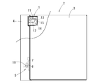
- the hinge device 1 of this embodiment supports a panel portion 4 constituting the front face of a body portion 3 of a housing 2 of an audio device so as to be openable and closable. It is.
- the casing 2 is formed in a rectangular parallelepiped shape as a whole, a portion having a predetermined thickness on the front surface portion is separated from the main body portion 3 as a panel portion 4, and is supported by the hinge device 1 so as to be opened and closed.
- the lock device 5 locks the closed state.
- the panel unit 4 includes various operation units, a display unit, and the like, and the main body unit 3 and the panel unit 4 are connected by a transmission mechanism (not shown) such as a detachable cable.
- the lock device 5 includes a hook 6 provided on the panel portion 4 and a lock piece 7 provided on the main body portion 3.
- the closed state is locked, and the locked state is released by rotating the lower end of the panel unit 4 so as to float slightly with respect to the main body 3 while pressing the unlock button 10 from this locked state. is there.
- the hook 6 is normally biased toward an upper position engaged with the lock piece 7 by an elastic body (not shown), and a part of the hook 6 is exposed to the side surface of the panel portion 4. And it is connected to the lock release button 10 provided on the side surface of the panel unit 4.
- the lock release button 10 When the lock release button 10 is pressed, the hook 6 moves slightly downward and is released from the engaged state with the lock piece 7.
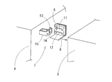
- the hinge device 1 includes a first guide groove 11 and a second guide groove 12 formed on the surface of a block 8 made of resin or the like fixed to the main body portion 3, and a panel portion 4.
- a first pin 13 and a second pin 14 that are provided on the fixed stay 15 and engage with the guide grooves 11 and 12 are provided.
- a member in which a pin is formed is referred to as a first member
- a member in which a guide groove is formed is referred to as a second member. That is, in this embodiment, the stay 15 may be referred to as a first member and the block 8 may be referred to as a second member.
- Two pins 13 and 14 provided on the panel unit 4 are provided on the stay 15 in parallel with each other.
- the stay 15 is bent in an L shape, and two pins 13 and 14 are fixed to the tip of the stay 15 so as to be aligned substantially in the vertical direction along the front surface of the panel portion 4.
- H the distance (pitch) between the pins 13 and 14 in the vertical direction.
- Both guide grooves 11 and 12 are formed on the surface of the block 8.
- two blocks 8 are fixed to a bracket 9 attached to the main body 3 so as to face each other (only one block is shown in FIG. 3, and the other is omitted).
- the guide grooves 11 and 12 are formed on the opposite surface in a mirror image arrangement obtained by transferring with a mirror, and pins 13 and 14 held by the stay 15 are arranged between them, and both ends of these pins 13 and 14 are guided.
- the structure is engaged with the grooves 11 and 12. Below, since the guide grooves 11 and 12 of both the blocks 8 have a mirror image relationship, the engagement state between one of them and the pins 13 and 14 will be described.
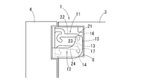
- the first guide groove 11 is disposed above the second guide groove 12, and the panel portion 4 is closed with respect to the main body 3 in the first guide groove 11.
- a first end 16 is formed for placing the first pin 13
- a second end 17 for placing the second pin 14 in the closed state is formed in the second guide groove 12.
- the first end portion 16 and the second end portion 17 are arranged so that the distance from the front surface of the main body 3 is substantially equal so that they are aligned in the vertical direction (vertical direction). , 14 is set equal to the separation distance.
- first end portion 16 of the first guide groove 11 has an arcuate end shape having an inner diameter substantially the same as the diameter of the first pin 13 so that the first pin 13 is pivotally contacted.
- the second end portion 17 of the second guide groove 12 is an oval shape to which the second pin 14 can move when the first end portion 16 of the first guide groove 11 is rotated about the first pin 13. A moving space is formed.
- the linear groove portion 22 continues from the first end portion 16 via the arc groove portion 21, and the second guide groove 12 also extends from the second end portion 17 via the arc groove portion 23. Is continuous.
- These arc groove portions 21 and 23 are each formed with a central angle of about 90 ° obliquely upward from below, and by forming the arc groove portions 21 and 23, the linear groove portions 22 and 24 are The first end 16 or the second end 17 is disposed obliquely above the position.
- the straight groove portion 22 of the first guide groove 11 and the straight groove portion 24 of the second guide groove 12 can be said to be arranged almost in parallel, but are arranged slightly inclined.
- a circle having a central angle of approximately 180 ° is formed at the end of the first guide groove 11 opposite to the first end 16 and the end of the second guide groove 12 opposite to the second end 17.
- Arc-shaped folded groove portions 25 and 26 are formed, respectively.
- the folded groove portions 25 and 26 are curved downward from the straight groove portions 22 and 24, and the end portions 27 and 28 are disposed below the straight groove portions 22 and 24.
- the end portion 27 of the folded groove portion 25 in the first guide groove 11 is formed in an arcuate end shape having an inner diameter substantially the same as the diameter of the first pin 13.
- the end 28 of the turn-back groove 26 in the second guide groove 12 is also formed in an arcuate end shape having an inner diameter substantially the same as the diameter of the second pin 14, but the end in the turn-up groove 25 of the first guide groove 11.
- a relief groove 29 is formed continuously so that the second pin 14 can move when the first pin 13 in the portion 27 is rotated around the center. That is, the end portion 27 of the turn-back groove portion 25 of the first guide groove 11 is a rotation end portion that rotatably contacts the first pin 13 (hereinafter, this end portion 27 may be referred to as a rotation end portion).
- the escape groove portion 29 of the second guide groove 12 is formed in an arc shape centering on the rotation end portion 27.
- the folding groove portion 26 of the second guiding groove 12 is disposed closer to the front surface of the main body 3 than the folding groove portion 25 of the first guiding groove 11, and therefore, the end portion of the folding groove portion 26 in the second guiding groove 12.
- 28 is disposed closer to the front surface of the main body part 3 than the end part (rotating end part) 27 of the folding groove part 25 in the first guide groove 11.
- the escape groove portion 29 of the second guide groove 12 is formed in the opposite direction from the end portion 28 of the folded groove portion 26 in the second guide groove 12 and extends so as to escape from the front end surface of the main body portion 3.
- An open end 30 through which the two pins 14 can be extracted from the second guide groove 12 is formed.
- the first guide groove 11 is formed so that the escape groove portion 35 branches off from the vicinity of the end portion of the linear groove portion 22 connected to the return groove portion 25.
- the relief groove 35 includes a bent groove 36 bent in an arc shape having a central angle of 90 ° extending upward from the end of the straight groove 22, and a linear shape extending in parallel with the straight groove 22 from the bent groove 36.
- an extension groove 37 extends so as to come out from the front end surface of the main body portion 3, and forms an open end 38 from which the first pin 13 can be extracted from the first guide groove 11.
- the open end 38 is formed in a tapered shape that gradually increases in width toward the outside.
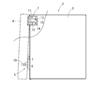
- the first pin 13 is disposed at the first end portion 16 of the first guide groove 11, and the second pin 14 is the second pin of the second guide groove 12.
- the hook 6 is partially exposed below the side surface of the panel portion 4 and includes the lock release button 10 connected to the hook 6.
- the hook 6 is usually fixed so as to be positioned upward by an elastic body.
- the subsequent panel opening operation causes interference between the panel portion 4 and the main body portion 3 as will be described later. It can be performed smoothly without making it.
- the moving space of the second end portion 17 is a minute space, but the hinge device 1 is disposed at the upper portion of the panel portion 4, and the hook 6 is disposed at the lower portion of the side surface of the panel portion 4. With this arrangement, the hook 6 moves sufficiently to release the locking device 5 at the lower side of the side surface of the panel portion 4 while the second pin 14 moves in the space portion of the second end portion 17. A distance can be secured.
- the stay 15 to which the pins 13 and 14 are fixed is indicated by a two-dot chain line.
- the entire panel unit 4 is separated from the main body unit 3 by holding the panel unit 4 and sliding it upward while lifting the panel unit 4 upward.
- the pins 13 and 14 of the panel portion 4 are moved in the arc groove portions 21 and 23, so that the upper end of the panel portion 4 is higher than the upper end of the main body portion 3.
- the entire body including the upper end is separated from the main body 3.
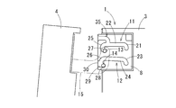
- the panel portion 4 is gradually inclined so that the lower end portion is lifted with respect to the main body portion 3 as it is separated from the main body portion 3. That is, as shown in FIG. 1, the linear groove portions 22, 24 of the first guide groove 11 and the second guide groove 12 gradually approach each other from the first end portion 16 and the second end portion 17 toward the opposite side. As shown in FIG. 8, the first pin 13 and the second pin 14 are moved from the arc groove portions 21 and 23 along the straight groove portions 22 and 24 of the guide grooves 11 and 12 as shown in FIG. When moved, the vertical distance between the linear groove portions 22 and 24 gradually becomes smaller than the vertical distance H between the pins 13 and 14, so that the pins 13 and 14 are gradually arranged obliquely.
- the panel part 4 is pulled forward while tilting.
- the straight groove portions 22 and 24 of both guide grooves 11 and 12 are arranged so as to be gradually reduced in the vertical distance, the panel portion 4 is gradually inclined as the panel portion 4 is pulled out.
- the inadvertent rotation can be regulated, and it can be pulled out smoothly without causing a collision with the main body 3 or the like.
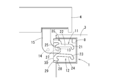
- the panel portion 4 As the panel portion 4 is pulled out, as shown in FIG. 9, when the pins 13 and 14 reach the return groove portions 25 and 26 from the straight groove portions 22 and 24, the panel portion 4 has an inclination angle with respect to the vertical direction. Move downwards while making it slightly smaller. In this state, the panel unit 4 is largely separated from the main body unit 3, so that the panel unit 4 does not interfere with the main body unit 3 even if the inclination angle is reduced (close to the vertical posture).
- the first pin 13 is rotated within the rotation end portion 27 of the turn-back groove portion 25 by rotating around the upper end portion so as to lift the lower end portion of the panel portion 4.
- the second pin 14 moves in an escape groove 29 extending in the opposite direction from the end 28 of the folded groove 26 and is pulled out from the open end 30.
- the panel portion 4 is supported by the main body portion 3 only at the upper end portion, and the lower end portion is in a free state.
- the upper end part of the panel part 4 is also spaced apart from the main-body part 3, even if it arrange
- the first pin 13 While moving the upper end of the panel part 4 with the second pin 14 removed from the second guide groove 12, the first pin 13 is moved so as to reverse the folded groove part 25, and then the panel part 4 is lifted. Then, after the first pin 13 is moved to the escape groove portion 35, when the panel portion 4 is pulled toward the front as shown in FIG. Then, the panel portion 4 is pulled out from the open end 38 at the tip, and the panel portion 4 is detached from the main body portion 3.
- the panel portion 4 is connected to the main body portion 3 only by the first pin 13 and can easily move in the vertical direction or the like, but the open end 38 of the first guide groove 11 is formed in a tapered shape. Therefore, the panel part 4 can be smoothly detached from the main body part 3.
- the panel part 4 can be removed from the main-body part 3 without using a tool etc. in particular. Then, by removing a transmission mechanism such as a cable that connects the main body 3 and the panel 4, one surface of the main body 4 is exposed. The operator can access the internal structure of the main body 4 from the exposed surface.
- the transmission mechanism can also be wireless communication.
- the removed panel unit 4 can be operated alone to transmit information to the main body unit 3. Moreover, when attaching the removed panel part 4 to the main-body part 3, it can attach easily by performing in the reverse order of the above operation.
- the hinge device 1 facilitates the panel opening operation while holding the panel portion 4 after the lower end portion of the panel portion 4 is separated from the main body portion 3 in the first stage of the panel opening operation.
- the panel portion 4 can be pulled out while being gradually inclined by the inclined linear groove portions 22 and 24, and the inadvertent rotation can be regulated to prevent the collision with the main body portion 3 and the like.
- the panel unit 4 can be opened greatly after being fully pulled out from the main body unit 3, for example, so that the opening / closing operation can be smoothly performed without causing interference between the panel unit 4 and the main body unit 3 and without using a tool or the like. Can be done.
- it is a simple structure which consists of the two guide grooves 11 and 12 and the two pins 13 and 14, and it can achieve size reduction and space saving.
- this invention is not limited to the said embodiment, A various change can be added in the range which does not deviate from the meaning of this invention.
- the panel unit 4 is held and moved, but the operation until the second pin 14 is extracted from the open end 30 of the second guide groove 12 is automatically performed using an actuator. Also good. If the actuator and the panel portion can be detachably engaged, the panel portion can be easily detached from the main body portion.
- the guide grooves 11 and 12 are formed on the opposing surfaces of the two blocks 8, and both ends of the pins 13 and 14 disposed between the two blocks 8 are engaged with the guide grooves 11 and 12.
- One block may be arranged on each side, and two pins may be supported on both sides of the panel, and the pins may be separately engaged with the guide grooves on the block surface.
- the guide groove of the block 8 may have a long hole shape penetrating in the thickness direction of the block 8.
- the pin is longer than the length of the guide groove (long hole) in the thickness direction of the block 8 (thickness of the block 8), and the pin is engaged with the guide groove so as to penetrate the block 8.
- the both end portions may be held by stays.
- the hinge device can be configured with one block and a pair of pins.
- a pin may be formed on the block 8 and a guide groove may be formed on the stay 15.
- the block 8 is fixed to the main body 3 and the stay 15 is fixed to the panel 4.
- the stay 15 is fixed to the main body 3 and the block 8 is fixed to the panel 4. It is good also as composition to do. That is, as long as the hinge device includes a first member that forms a pin and a second member that forms a guide groove, and rotatably supports the fixed parts of the first member and the second member, There is no restriction
Landscapes
- Engineering & Computer Science (AREA)
- Mechanical Engineering (AREA)
- General Engineering & Computer Science (AREA)
- Civil Engineering (AREA)
- Structural Engineering (AREA)
- Casings For Electric Apparatus (AREA)
- Pivots And Pivotal Connections (AREA)
- Hinges (AREA)
- Snaps, Bayonet Connections, Set Pins, And Snap Rings (AREA)
Abstract
Description
例えば、特許文献1には、固定体に対して2個のリンクで回動体の回動を案内するスライド蝶番が開示されており、これらリンクを挟むようにねじりばねが設けられ、そのねじりばねの中央部がピンにより支持されている。
また、特許文献2には、2本のガイド溝にピンをそれぞれ係合し、これらのピンに対してガイド溝に沿う直線的な移動とガイド溝内での回動との両方の動きができるようにして、蓋体を本体部に干渉することなく開閉することができるようにした車両用内装部材が開示されている。
第1端部及び第2端部では第1ピンを中心として第1部材を回動できるようにしたが、スライド操作時にも回動してしまうと両部材が干渉して開放操作を妨げるおそれがある。本発明のヒンジ装置では、両誘導溝を第1端部及び第2端部から反対側に向かうにしたがって漸次接近するように配置したから、ピンを移動させると、徐々に第2部材が第1部材に対して傾斜することになり、第2部材の不用意な回動を規制して両部材の干渉を防止し、スライド操作を円滑かつ確実に行わせることができる。
第1部材と第2部材の閉塞状態から第1部材を誘導溝に沿って移動した後、回動端部において第1ピンを中心として回動させることにより、第2部材を第1部材に対して大きく開くことができる。第1部材と第2部材とを大きく離間させた後の回動操作であるので、これらの干渉を防止することができる。
第2部材を第1部材に対して大きく開いた後に、第1部材から離脱させることができ、部材相互の干渉を防止するとともに、離脱操作を容易にすることができる。
この実施形態のヒンジ装置1は、図2及び図3に示すように、音響機器の筐体2の本体部3に対して、その前面を構成しているパネル部4を開閉可能に支持するものである。
この音響機器は、その筐体2が全体として直方体状に形成され、前面部の所定厚さの部分がパネル部4として本体部3から切り離され、ヒンジ装置1によって開閉可能に支持されるとともに、閉塞状態のときにはロック装置5によって閉塞状態にロックされる構成である。なお、パネル部4には各種操作部、ディスプレー部等を有しており、本体部3とパネル部4とは、着脱可能なケーブルなどによる伝送機構(図示略)によって接続されている。
パネル部4に設けられるピン13,14は、ステー15に2本相互に平行に設けられている。図示例では、ステー15がL字状に屈曲形成されており、その先端部に、パネル部4の前面に沿うほぼ上下方向に並んで2本のピン13,14が固定されている。これらピン13,14の上下方向の離間距離(ピッチ)をHとする。
この場合、第1端部16及び第2端部17は、上下方向(垂直方向)に並ぶように本体部3の前面からの距離はほぼ等しく配置され、その上下方向の離間距離は両ピン13,14の離間距離と等しく設定されている。また、第1誘導溝11の第1端部16は、第1ピン13を回動自在に当接するように、第1ピン13の直径とほぼ同じ内径の円弧面状の終端形状をなしており、第2誘導溝12の第2端部17は、第1誘導溝11の第1端部16で第1ピン13を中心として回動させたときに、第2ピン14が移動できる長円形の移動空間を形成している。
また、第2誘導溝12の逃がし溝部29は、第2誘導溝12における折り返し溝部26の端部28から反対方向に向かって形成され、本体部3の前端面から抜け出るように延びており、第2ピン14を第2誘導溝12から抜き出すことが可能な開放端30を形成している。
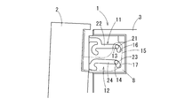
まず、図2及び図4に示すパネル部4の閉塞状態では、第1ピン13は第1誘導溝11の第1端部16に配置され、第2ピン14は第2誘導溝12の第2端部17に配置されている。フック6は、前述したようにパネル部4の側面下方に一部が露出し、フック6と接続するロック解除ボタン10を備えている。フック6は、通常は弾性体により上方に位置するように固定されている。
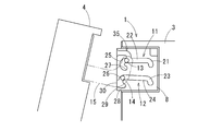
このロック状態から、ロック解除ボタン10を押下するとフック6は下方に若干移動し、ロック片7との係合状態から解放される。このロック片7から解放された状態を維持しながらパネル部4の下端部を本体部3に対して手前に引きながら若干回動する。このパネル部4を回動すると、図5及び図6に示すように、第1ピン13を中心として第2ピン14が第2端部17の空間部内を移動し、その移動によりパネル部4のフック6が本体部3のロック片7から離間し、ロック装置5の解除状態となる。このロック装置5の解除状態においては、図5に示すようにパネル部4の下端部が本体部3から離間した状態になる。
このようにパネル開放操作の最初の段階でパネル部4の下端部を本体部3から離間させることにより、後述するように、その後のパネル開放操作をパネル部4と本体部3との干渉を生じさせることなく円滑に行わせることができる。また、第2端部17の移動空間は微小な空間であるが、ヒンジ装置1はパネル部4の上部に配置され、フック6はパネル部4の側面下部に配置されている。このように配置することで、第2ピン14が第2端部17の空間部を移動する間に、パネル部4の側面下部においては、フック6がロック装置5を解除するのに十分な移動距離を確保することができる。
なお、この図5~図10までにおいては、ピン13,14を固定しているステー15を二点鎖線で示す。
このように、両誘導溝11,12の直線溝部22,24を徐々に上下間隔が小さくなるように傾斜させて配置したことから、パネル部4を引き出すにしたがって徐々にパネル部4が傾斜させられ、その不用意な回動を規制して、本体部3への衝突等を生じることなく円滑に引き出すことができる。
この場合は、パネル部4は本体部3に対して第1ピン13のみによって接続されていて、上下方向等に動き易いが、第1誘導溝11の開放端38がテーパ状に形成されていることから、パネル部4を本体部3から円滑に離脱させることができる。
また、取り外したパネル部4を本体部3に取り付ける場合は、以上の操作の逆順で行うことにより、簡単に取り付けることができる。
すでに説明したように、このヒンジ装置1は、パネル開放操作の最初の段階でパネル部4の下端部を本体部3から離間させ、その後のパネル部4を持ちながらのパネル開放操作を容易にするとともに、傾斜した直線溝部22,24によりパネル部4を徐々に傾斜させながら引き出すことができ、その不用意な回動を規制して本体部3への衝突等を防止することができる。そして、本体部3から十分に引き出した後にパネル部4を大きく開くことが可能になるなど、パネル部4と本体部3との干渉を生じることなく、また工具等を用いることなく開閉操作を円滑に行わせることができる。
また、2個の誘導溝11,12と2本のピン13,14とからなる簡単な構成であり、小型化、省スペース化を図ることができる。
例えば、実施形態ではパネル部4を手に持って移動するようにしたが、第2ピン14を第2誘導溝12の開放端30から抜き出す操作までをアクチュエータを用いて自動で行わせるようにしてもよい。アクチュエータとパネル部とは、着脱自在に係合できる構成としておけば、パネル部を本体部から離脱させることも容易である。
また、2個のブロック8の対向面に誘導溝11,12を形成して、その間に配置したピン13,14の両端部が誘導溝11,12に係合する構成としたが、本体部の両側部に1個ずつブロックを配置するとともに、2本のピンをパネル部の両側部にそれぞれ支持し、これらブロック表面の誘導溝に別々にピンが係合する構成としてもよい。
あるいは、ブロック8の誘導溝をブロック8の厚さ方向に貫通する長孔状のものとしてもよい。この場合、ピンはブロック8の厚さ方向における誘導溝(長孔)の長さ(ブロック8の厚さ)よりも長いものを用い、ブロック8を貫通するように誘導溝にピンを係合させ、その両端部をステーにより保持するようにしてもよい。このように形成することで一つのブロックと一対のピンでヒンジ装置を構成することができる。
また、実施形態とは逆に、ブロック8にピンを形成し、ステー15に誘導溝を形成してもよい。また、実施形態では本体部3にブロック8を固定し、パネル部4にステー15を固定しているが、その逆に、本体部3にステー15を固定し、パネル部4にブロック8を固定する構成としてもよい。すなわち、ピンを形成する第1部材と誘導溝を形成する第2部材とを備え、それら第1部材と第2部材の固定部品を回動可能に支持するヒンジ装置であれば、第1部材や第2部材が固定される部位に特に制限はない。
Claims (7)
- 第1部材と第2部材とを回動可能に支持するヒンジ装置であって、
前記第1部材に相互にほぼ平行に形成された第1誘導溝及び第2誘導溝と、
前記第2部材に設けられ前記第1誘導溝にスライド自在に係合する第1ピン及び前記第2誘導溝にスライド自在に係合する第2ピンと、を備え、
前記第1誘導溝は、前記第1ピンを回動可能に当接する第1端部を有し、
前記第2誘導溝は、前記第1誘導溝の第1端部に前記第1ピンが配置されたときに該第1ピンを中心として前記第2ピンを回動可能に配置できる移動空間が形成された第2端部を有している
ヒンジ装置。 - 請求項1記載のヒンジ装置であって、
前記第1誘導溝と前記第2誘導溝とは、前記第1端部及び前記第2端部からそれぞれ反対側に向かうにしたがって漸次接近するように配置されている
ヒンジ装置。 - 請求項1又は2に記載のヒンジ装置であって、
前記第1誘導溝における前記第1端部とは反対側に、前記第1ピンを回動可能に当接する回動端部を有し、前記第2誘導溝における前記第2端部とは反対側に、前記第1ピンが前記回動端部に配置されたときに該第1ピンを中心として前記第2ピンを回動可能に配置できる第1の逃がし溝部が形成されている
ヒンジ装置。 - 請求項3に記載のヒンジ装置であって、
前記回動端部に、前記第1ピンを前記第1部材から抜き出すことが可能な第1の開放端が接続される
ヒンジ装置。 - 請求項4に記載のヒンジ装置であって、
前記第2ピンが前記第2誘導溝から外れた状態で、前記第1ピンを前記回動端部から前記第1の開放端まで誘導する第2の逃がし溝部が形成されている
ヒンジ装置。 - 請求項3から5のいずれか一項に記載のヒンジ装置であって、
前記第1の逃がし溝部に、前記第2ピンを前記第1部材から抜き出すことが可能な第2の開放端が接続されている
ヒンジ装置。 - 本体部とその前面部を構成するパネル部とを備える筐体であって、
前記本体部とパネル部とのいずれか一方の一部が前記第1部材であり、その他方の一部が前記第2部材であり、
請求項1から6のいずれか一項に記載のヒンジ装置により開閉可能に支持されてなる筐体。
Priority Applications (4)
| Application Number | Priority Date | Filing Date | Title |
|---|---|---|---|
| KR1020147034410A KR101699776B1 (ko) | 2012-06-11 | 2013-06-11 | 힌지 장치 및 하우징 |
| EP13804655.2A EP2860413A4 (en) | 2012-06-11 | 2013-06-11 | ARTICULATION DEVICE AND HOUSING |
| CN201380029888.5A CN104350293B (zh) | 2012-06-11 | 2013-06-11 | 铰接装置和外壳 |
| US14/406,929 US9376845B2 (en) | 2012-06-11 | 2013-06-11 | Hinge device and housing |
Applications Claiming Priority (2)
| Application Number | Priority Date | Filing Date | Title |
|---|---|---|---|
| JP2012132231A JP6186673B2 (ja) | 2012-06-11 | 2012-06-11 | ヒンジ装置及び筐体 |
| JP2012-132231 | 2012-06-11 |
Publications (1)
| Publication Number | Publication Date |
|---|---|
| WO2013187393A1 true WO2013187393A1 (ja) | 2013-12-19 |
Family
ID=49758215
Family Applications (1)
| Application Number | Title | Priority Date | Filing Date |
|---|---|---|---|
| PCT/JP2013/066042 WO2013187393A1 (ja) | 2012-06-11 | 2013-06-11 | ヒンジ装置及び筐体 |
Country Status (6)
| Country | Link |
|---|---|
| US (1) | US9376845B2 (ja) |
| EP (1) | EP2860413A4 (ja) |
| JP (1) | JP6186673B2 (ja) |
| KR (1) | KR101699776B1 (ja) |
| CN (1) | CN104350293B (ja) |
| WO (1) | WO2013187393A1 (ja) |
Families Citing this family (22)
| Publication number | Priority date | Publication date | Assignee | Title |
|---|---|---|---|---|
| US9982470B2 (en) * | 2012-11-09 | 2018-05-29 | Ford Global Technologies, Llc | Soft close mechanism for a closure |
| EP2931201A1 (en) * | 2012-12-11 | 2015-10-21 | Koninklijke Philips N.V. | Enhanced hinge and method for pivotally and removably connecting a member with a structure |
| CN107208437A (zh) * | 2015-02-26 | 2017-09-26 | 华为技术有限公司 | 门与悬挂机构的组件以及该组件与长形壳体的组件 |
| JP6726494B2 (ja) * | 2016-03-18 | 2020-07-22 | マツダ株式会社 | 自動車の開閉体ロック構造、及び自動車の開閉体ロック方法 |
| CN106196819A (zh) | 2016-08-05 | 2016-12-07 | 青岛海尔股份有限公司 | 冰箱 |
| EP3366899B1 (en) * | 2016-12-28 | 2019-11-06 | Komatsu Ltd. | Utility vehicle, and method for adjusting position of movable part of utility vehicle |
| CN107420025A (zh) * | 2017-08-30 | 2017-12-01 | 国家电网公司 | 便携式阻尼伸缩梯 |
| CN108443311A (zh) * | 2018-06-06 | 2018-08-24 | 合肥联宝信息技术有限公司 | 一种调节装置及电子设备 |
| JP7023582B2 (ja) * | 2018-06-11 | 2022-02-22 | 中野冷機株式会社 | ショーケースのフードカバー装置 |
| CN109246947B (zh) * | 2018-09-26 | 2020-12-29 | 东软医疗系统股份有限公司 | 外罩及其打开机构 |
| JP6659988B1 (ja) * | 2019-03-26 | 2020-03-04 | 富士通クライアントコンピューティング株式会社 | ヒンジ装置および電子機器の筐体 |
| WO2021012656A1 (zh) * | 2019-07-23 | 2021-01-28 | 青岛海尔电冰箱有限公司 | 带有装饰片的铰链组件及具有其的冰箱 |
| CN112282543B (zh) * | 2019-07-23 | 2022-07-12 | 青岛海尔电冰箱有限公司 | 冰箱 |
| CN112444085B (zh) * | 2019-08-28 | 2022-02-22 | 青岛海尔电冰箱有限公司 | 带有切换组件的嵌入式多门冰箱 |
| CN112444084B (zh) * | 2019-08-28 | 2022-06-28 | 青岛海尔电冰箱有限公司 | 可辅助开门的嵌入式冰箱 |
| CN112444086B (zh) * | 2019-08-28 | 2021-10-29 | 青岛海尔电冰箱有限公司 | 带有多轴铰链组件的嵌入式冰箱 |
| CN112444088B (zh) * | 2019-08-28 | 2022-04-29 | 青岛海尔电冰箱有限公司 | 带有铰链组件的冰箱 |
| CN112444087B (zh) * | 2019-08-28 | 2022-04-26 | 青岛海尔电冰箱有限公司 | 自由嵌入式冰箱 |
| CN112462867B (zh) * | 2019-09-06 | 2022-09-02 | 英业达科技有限公司 | 具有可卸式托架的机箱 |
| CN114059873B (zh) * | 2020-08-05 | 2023-05-16 | 青岛海尔电冰箱有限公司 | 铰链组件及具有其的家具 |
| KR20230004166A (ko) * | 2021-06-30 | 2023-01-06 | 주식회사 쏠리드 | 마운트 브라켓 |
| US11940202B2 (en) * | 2022-02-04 | 2024-03-26 | Haier Us Appliance Solutions, Inc. | Appliances with releasable door hinges and tether systems |
Citations (7)
| Publication number | Priority date | Publication date | Assignee | Title |
|---|---|---|---|---|
| JPS63101670U (ja) * | 1986-12-22 | 1988-07-01 | ||
| JPH02117238U (ja) * | 1989-03-08 | 1990-09-19 | ||
| JPH04309681A (ja) | 1991-04-08 | 1992-11-02 | Nhk Spring Co Ltd | スライド蝶番 |
| JP2005146625A (ja) * | 2003-11-14 | 2005-06-09 | Hitoshi Nishitani | ヒンジ装置 |
| JP2005232875A (ja) * | 2004-02-20 | 2005-09-02 | Nitto Island Key Kk | 家具用蝶番 |
| JP2007221230A (ja) * | 2006-02-14 | 2007-08-30 | Funai Electric Co Ltd | スキャナ付きレーザプリンタ装置およびドア装置 |
| JP4203196B2 (ja) | 1999-12-03 | 2008-12-24 | 小島プレス工業株式会社 | 車両用内装部材 |
Family Cites Families (33)
| Publication number | Priority date | Publication date | Assignee | Title |
|---|---|---|---|---|
| US552485A (en) * | 1895-12-31 | Trunk | ||
| US1075130A (en) * | 1912-09-28 | 1913-10-07 | Edward L Ackerman | Concealed hinge. |
| US2206499A (en) * | 1939-03-09 | 1940-07-02 | Dumelin Charles | Concealed hinge |
| US2435670A (en) * | 1945-05-05 | 1948-02-10 | Eastern Steel Products Ltd | Closure for hoppers and the like |
| US2584173A (en) * | 1947-12-02 | 1952-02-05 | Jess Van Fowler | Tiltable panel assembly |
| US2793387A (en) * | 1955-08-22 | 1957-05-28 | Albert W Odell | Pivotal connection |
| US2869958A (en) | 1956-11-28 | 1959-01-20 | Hough John Jay | Mechanism for mounting electrical units |
| US2867839A (en) * | 1957-10-17 | 1959-01-13 | Midwest Mfg Corp | Door hinge |
| US3065498A (en) * | 1959-12-11 | 1962-11-27 | Jervis Corp | Hinge device |
| US4316082A (en) * | 1980-02-06 | 1982-02-16 | Honeywell Inc. | Computer control apparatus |
| US4368866A (en) * | 1980-06-27 | 1983-01-18 | International Jensen Incorporated | Mounting bracket and mounting arrangement |
| US5169221A (en) * | 1990-09-04 | 1992-12-08 | General Devices Co., Inc. | Pivotable drawer slide mount with pivot controlling guide slot |
| JP2816899B2 (ja) | 1990-11-30 | 1998-10-27 | 東北大学長 | 坑井掘削中の放出弾性波の三次元粒子運動解析による地下構造評価方法 |
| JPH0596361U (ja) * | 1992-06-04 | 1993-12-27 | 株式会社エイアンドアイ | ヒンジ |
| US5603682A (en) * | 1995-02-06 | 1997-02-18 | Grider; Sherman P. | Back-pad cushion adjusting device for use on a multi-station gym |
| KR200205397Y1 (ko) * | 1997-08-30 | 2000-12-01 | 구자홍 | 냉장고의 도어힌지 구조 |
| AU2528700A (en) * | 1999-02-09 | 2000-08-29 | Decoma Exterior Trim Inc. | Mounting hardware for a hard tonneau cover |
| US6493906B2 (en) * | 2001-02-02 | 2002-12-17 | Charles Matteau | Hinge structure |
| US6846052B2 (en) * | 2001-04-05 | 2005-01-25 | Sligh Furniture Company | Desk with concealed keyboard well |
| US20020164197A1 (en) * | 2001-04-06 | 2002-11-07 | Lee Ta Yi | Pivotal connector for scanner |
| TWI220942B (en) * | 2001-06-01 | 2004-09-11 | Wistron Corp | Hard disk retraction mechanism |
| KR100443983B1 (ko) * | 2002-01-15 | 2004-08-09 | 삼성전자주식회사 | 냉장고 |
| US7028370B2 (en) * | 2003-03-31 | 2006-04-18 | Thk Co., Ltd. | Retracting apparatus, drawer apparatus and sliding door apparatus |
| US7661777B2 (en) * | 2004-05-07 | 2010-02-16 | Rimco, Inc. | Dolly dropdown box drawer for a tow truck |
| CN2727480Y (zh) * | 2004-08-10 | 2005-09-21 | 陈文琪 | 双轴铰 |
| US7536752B2 (en) * | 2005-01-21 | 2009-05-26 | Leviton Manufacturing Company, Inc. | Rack mounted component door system and method |
| GB2439328B (en) * | 2006-06-22 | 2012-07-04 | Panasonic Mfg Uk Ltd | Domestic appliance with concealed hinge |
| US7338107B1 (en) * | 2006-09-01 | 2008-03-04 | Snf, Inc | Tailgate and hinge assembly for pickup truck |
| US7685680B2 (en) * | 2007-06-05 | 2010-03-30 | Hsiang-Chi Chien | Rotatable slide hinge |
| US7752712B2 (en) * | 2008-01-21 | 2010-07-13 | Shin Zu Shing Co., Ltd. | Hinge |
| CN101725620B (zh) * | 2008-10-29 | 2012-03-28 | 鸿富锦精密工业(深圳)有限公司 | 铰链结构及采用该铰链结构的电脑机箱 |
| US8338767B2 (en) * | 2010-02-09 | 2012-12-25 | Whirlpool Corporation | Hinge mechanism for a home appliance providing door motion in a non-circular path |
| TW201143583A (en) * | 2010-05-18 | 2011-12-01 | Hon Hai Prec Ind Co Ltd | Stack plate and server assembly using the same |
-
2012
- 2012-06-11 JP JP2012132231A patent/JP6186673B2/ja not_active Expired - Fee Related
-
2013
- 2013-06-11 KR KR1020147034410A patent/KR101699776B1/ko active IP Right Grant
- 2013-06-11 CN CN201380029888.5A patent/CN104350293B/zh not_active Expired - Fee Related
- 2013-06-11 EP EP13804655.2A patent/EP2860413A4/en not_active Withdrawn
- 2013-06-11 WO PCT/JP2013/066042 patent/WO2013187393A1/ja active Application Filing
- 2013-06-11 US US14/406,929 patent/US9376845B2/en not_active Expired - Fee Related
Patent Citations (7)
| Publication number | Priority date | Publication date | Assignee | Title |
|---|---|---|---|---|
| JPS63101670U (ja) * | 1986-12-22 | 1988-07-01 | ||
| JPH02117238U (ja) * | 1989-03-08 | 1990-09-19 | ||
| JPH04309681A (ja) | 1991-04-08 | 1992-11-02 | Nhk Spring Co Ltd | スライド蝶番 |
| JP4203196B2 (ja) | 1999-12-03 | 2008-12-24 | 小島プレス工業株式会社 | 車両用内装部材 |
| JP2005146625A (ja) * | 2003-11-14 | 2005-06-09 | Hitoshi Nishitani | ヒンジ装置 |
| JP2005232875A (ja) * | 2004-02-20 | 2005-09-02 | Nitto Island Key Kk | 家具用蝶番 |
| JP2007221230A (ja) * | 2006-02-14 | 2007-08-30 | Funai Electric Co Ltd | スキャナ付きレーザプリンタ装置およびドア装置 |
Non-Patent Citations (1)
| Title |
|---|
| See also references of EP2860413A4 |
Also Published As
| Publication number | Publication date |
|---|---|
| KR101699776B1 (ko) | 2017-02-13 |
| CN104350293A (zh) | 2015-02-11 |
| US20150167367A1 (en) | 2015-06-18 |
| US9376845B2 (en) | 2016-06-28 |
| KR20150007343A (ko) | 2015-01-20 |
| EP2860413A1 (en) | 2015-04-15 |
| JP6186673B2 (ja) | 2017-08-30 |
| JP2013256769A (ja) | 2013-12-26 |
| EP2860413A4 (en) | 2016-02-24 |
| CN104350293B (zh) | 2017-03-08 |
Similar Documents
| Publication | Publication Date | Title |
|---|---|---|
| WO2013187393A1 (ja) | ヒンジ装置及び筐体 | |
| US9132778B2 (en) | Luggage board movement mechanism | |
| RU2558538C2 (ru) | Устройство для открывания и закрывания крышки | |
| KR101481352B1 (ko) | 도어 아웃사이드핸들 | |
| JP6227919B2 (ja) | フック外れ止め装置 | |
| JP5565760B2 (ja) | 引出式収納装置 | |
| JP2010154149A (ja) | 開閉式小型電子機器 | |
| CN103038963A (zh) | 竖直电缆管理器门 | |
| KR101704060B1 (ko) | 자동차용 아웃사이드 도어 핸들의 조립 구조 | |
| CN103192614B (zh) | 承载机构及其相关印表机 | |
| JP2008208588A (ja) | アウトサイドドアハンドル | |
| JP6625917B2 (ja) | 車両用フードロック装置 | |
| US7458482B2 (en) | Protective cover | |
| JP2009039508A (ja) | ベッド装置 | |
| JP2001180358A (ja) | 自動車のグラブボックス | |
| JP4141814B2 (ja) | オーバーヘッドコンソール | |
| JP2005263237A (ja) | 蓋付ボックスの蓋開閉機構 | |
| JP6895746B2 (ja) | 蓋の開閉構造 | |
| JP2014105485A (ja) | 折戸 | |
| JP4927025B2 (ja) | ステー | |
| JP5387816B2 (ja) | 回動可能な筐体の連結装置および方法並びにそれを用いた携帯機器 | |
| JP4870138B2 (ja) | 扉の保持装置 | |
| KR101592969B1 (ko) | 차량용 도어의 맵포켓 | |
| WO2010113620A1 (ja) | ヒンジ装置及びヒンジ装置を用いた電子機器 | |
| JPH0428855Y2 (ja) |
Legal Events
| Date | Code | Title | Description |
|---|---|---|---|
| 121 | Ep: the epo has been informed by wipo that ep was designated in this application |
Ref document number: 13804655 Country of ref document: EP Kind code of ref document: A1 |
|
| ENP | Entry into the national phase |
Ref document number: 20147034410 Country of ref document: KR Kind code of ref document: A |
|
| WWE | Wipo information: entry into national phase |
Ref document number: 14406929 Country of ref document: US Ref document number: 2013804655 Country of ref document: EP |
|
| NENP | Non-entry into the national phase |
Ref country code: DE |