WO2013179375A1 - Machine électrique rotative à couple composite - Google Patents
Machine électrique rotative à couple composite Download PDFInfo
- Publication number
- WO2013179375A1 WO2013179375A1 PCT/JP2012/063672 JP2012063672W WO2013179375A1 WO 2013179375 A1 WO2013179375 A1 WO 2013179375A1 JP 2012063672 W JP2012063672 W JP 2012063672W WO 2013179375 A1 WO2013179375 A1 WO 2013179375A1
- Authority
- WO
- WIPO (PCT)
- Prior art keywords
- permanent magnet
- magnetic flux
- rotor
- slit
- stator
- Prior art date
Links
Images


Classifications
-
- H—ELECTRICITY
- H02—GENERATION; CONVERSION OR DISTRIBUTION OF ELECTRIC POWER
- H02K—DYNAMO-ELECTRIC MACHINES
- H02K1/00—Details of the magnetic circuit
- H02K1/06—Details of the magnetic circuit characterised by the shape, form or construction
- H02K1/22—Rotating parts of the magnetic circuit
- H02K1/27—Rotor cores with permanent magnets
- H02K1/2706—Inner rotors
- H02K1/272—Inner rotors the magnetisation axis of the magnets being perpendicular to the rotor axis
- H02K1/274—Inner rotors the magnetisation axis of the magnets being perpendicular to the rotor axis the rotor consisting of two or more circumferentially positioned magnets
- H02K1/2753—Inner rotors the magnetisation axis of the magnets being perpendicular to the rotor axis the rotor consisting of two or more circumferentially positioned magnets the rotor consisting of magnets or groups of magnets arranged with alternating polarity
- H02K1/276—Magnets embedded in the magnetic core, e.g. interior permanent magnets [IPM]
- H02K1/2766—Magnets embedded in the magnetic core, e.g. interior permanent magnets [IPM] having a flux concentration effect
-
- H—ELECTRICITY
- H02—GENERATION; CONVERSION OR DISTRIBUTION OF ELECTRIC POWER
- H02K—DYNAMO-ELECTRIC MACHINES
- H02K1/00—Details of the magnetic circuit
- H02K1/06—Details of the magnetic circuit characterised by the shape, form or construction
- H02K1/22—Rotating parts of the magnetic circuit
- H02K1/27—Rotor cores with permanent magnets
- H02K1/2706—Inner rotors
- H02K1/272—Inner rotors the magnetisation axis of the magnets being perpendicular to the rotor axis
- H02K1/274—Inner rotors the magnetisation axis of the magnets being perpendicular to the rotor axis the rotor consisting of two or more circumferentially positioned magnets
- H02K1/2753—Inner rotors the magnetisation axis of the magnets being perpendicular to the rotor axis the rotor consisting of two or more circumferentially positioned magnets the rotor consisting of magnets or groups of magnets arranged with alternating polarity
- H02K1/276—Magnets embedded in the magnetic core, e.g. interior permanent magnets [IPM]
- H02K1/2766—Magnets embedded in the magnetic core, e.g. interior permanent magnets [IPM] having a flux concentration effect
- H02K1/2773—Magnets embedded in the magnetic core, e.g. interior permanent magnets [IPM] having a flux concentration effect consisting of tangentially magnetized radial magnets
Definitions
- the present invention relates to a composite torque type rotating electrical machine using a low residual magnetic flux density permanent magnet such as a ferrite magnet.
- Patent Document 1 In a synchronous motor in which a permanent magnet is embedded in a rotor, a magnetic pole central axis by a permanent magnet is called a d-axis, and an axis that is electrically and magnetically orthogonal to the d-axis is called a q-axis.
- Patent Document 2 As a conventional structure, an example in which a plurality of permanent magnets are embedded in the d-axis direction is known (see, for example, Patent Document 1).
- Patent Document 2 is known as a structure of a permanent magnet type rotating electrical machine that combines reluctance torque.
- Patent Document 3 discloses a rotor of a permanent magnet type rotating machine that simplifies the configuration by reducing the number of permanent magnets while obtaining a large reluctance torque.
- the combined torque type rotating electric machine achieves high torque by combining the reluctance torque by the armature magnetic flux generated by the armature winding of the stator and the magnet torque by the magnet magnetic flux of the permanent magnet.
- Patent Document 1 has a plurality of permanent magnets embedded in the d-axis direction.
- an iron core exists over the entire outer peripheral portion of the rotor on the outer peripheral side of the permanent magnet, and a closed-loop armature generated by the armature winding of the stator in this iron core portion
- the structure is such that the spatial harmonics of the magnetic flux easily flow in.
- This closed-loop spatial harmonic hardly contributes to the reluctance torque, but increases the magnetic saturation tendency of the iron core by passing through the stator and rotor iron cores, so that the effective amount of magnetic flux that contributes to the reluctance torque is sufficient. It was not obtained.
- the structure is such that the permanent magnets are greatly opened so that the magnetic flux can easily flow in from one q-axis direction (Patent Document 1, FIG. 2).
- the magnetic flux flowing in from one q-axis direction passes further through the inner peripheral side of the permanent magnet embedded on the inner peripheral side on the d-axis and flows out from the other q-axis direction.
- this path has a long magnetic path, the magnetic resistance increases, and the magnetic loss increases accordingly.
- Patent Document 2 is a typical structure as a structure of a permanent magnet type rotating electrical machine that combines reluctance torque.
- the reluctance torque in this structure is generated in the iron core portion on the outer peripheral side from the permanent magnet.
- the permanent magnet is arranged closer to the inner circumference to increase the size of the iron core. In this case, the circumferential length of the rotor of the permanent magnet is small. This shortens the magnet torque.
- neodymium magnets are used especially for permanent magnets located on the outer periphery of the rotor in order to avoid an increase in magnet torque and permanent demagnetization, but rare earth metals such as neodymium and dysprosim are used. Availability is very poor and very expensive. On the other hand, ferrite magnets are readily available and inexpensive, but have a problem of low permanent magnetism due to low magnetic force due to low magnetic force and easy demagnetization due to low holding power.
- Patent Document 3 discloses a rotor of a permanent magnet type rotating machine that achieves a simplified configuration by reducing the number of permanent magnets while obtaining a large reluctance torque.
- the magnetic path of the magnetic flux from the stator passes between the end portion in the longitudinal direction of the permanent magnet located on the outer peripheral side and the permanent magnet located in the radial direction, passes through the trapezoidal inside, and the permanent magnet
- the magnetic flux from the stator is to shortcut the inside of the trapezoidal shape as described that it will take a path that passes between the other end in the longitudinal direction of the permanent magnet and the permanent magnet located next to it. Become. For this reason, magnetic flux saturation is likely to occur in the iron core portion inside the trapezoidal shape, and the magnetic resistance increases.
- the present invention has been made in view of the above problems, and by blocking the inflow of the space harmonics of the closed-loop magnetic flux generated by the armature winding of the stator to the core portion of the rotor, the ferrite magnet
- the torque of the composite torque type rotating electrical machine using a permanent magnet having a low residual magnetic flux density such as the above is increased.
- a composite torque type rotating electric machine includes a stator in which armature windings are arranged on a plurality of teeth in a circumferential direction at regular intervals, and A rotor having a permanent magnet in a cylindrical iron core laminated with electromagnetic steel plates, and disposed inside the stator, It is provided over the outer peripheral portion of the rotor in the circumferential direction, and includes a magnetic flux blocking portion that blocks a closed loop magnetic flux generated around the stator winding.
- the magnetic flux blocking part is composed of a plurality of permanent magnets and a non-magnetic body part provided between the plurality of permanent magnets.
- a distance between the permanent magnet and the nonmagnetic portion is smaller than an interval between teeth of the armature winding.
- the non-magnetic body part is a slit part composed of a plurality of slits, and a distance between the permanent magnet and the slit part, and between the slits The distance is smaller than the interval between the teeth of the armature winding.
- the non-magnetic body portion is a gap, and a distance between the permanent magnet and the gap is smaller than an interval between teeth of the armature winding. It is characterized by that.
- the composite torque type rotating electric machine of the present invention includes a stator in which armature windings are arranged on a plurality of teeth in the circumferential direction at regular intervals, A rotor composed of a cylindrical iron core laminated with electromagnetic steel plates and disposed inside the stator; and The rotor includes a plurality of permanent magnets arranged in the circumferential direction on the outer periphery, A gap provided in the middle in the circumferential direction of the plurality of permanent magnets of the rotor; It is provided between the said permanent magnet and the said space
- the slit portion is formed on the outer peripheral side with respect to a straight line connecting the corner portion on the inner peripheral side of the permanent magnet and the center of the outer peripheral side of the gap portion. It is characterized by.
- the distance between the permanent magnet and the slit portion, and the distance between the slit portion and the gap are the intervals between the teeth of the armature winding. It is characterized by being smaller than.
- a distance between slits constituting the slit portion is smaller than an interval between teeth of the armature winding.
- a permanent magnet rotating electrical machine using a permanent magnet having a low residual magnetic flux density such as a ferrite magnet
- a permanent magnet having a low residual magnetic flux density such as a ferrite magnet
- Example It is a figure which shows magnetic flux distribution by the electromagnetic field analysis of this invention Example. It is a figure which shows the example of the comparison and examination model by electromagnetic field analysis. It is a figure which shows the result by electromagnetic field analysis. It is sectional drawing of the radial direction of the compound torque type rotary electric machine which concerns on Example 2 of this invention. It is the principal part enlarged view of a rotor structure similarly.
- the embodiment of the present invention considers each action obtained from the following configurations (a) to (f).
- a permanent magnet serving as a magnetic flux blocking means for blocking the inflow and outflow of the armature magnetic flux generated by the armature windings arranged on the stator teeth on the outer peripheral side on the d-axis of the rotor. Deploy.
- B A rectangular permanent magnet that serves to prevent magnetic flux shorting between adjacent magnetic poles and rectify the magnetic path is disposed on the inner peripheral side.
- C A permanent magnet that serves to prevent short-circuit magnetic flux with the adjacent magnetic pole is disposed on the q-axis of the rotor.
- a trapezoidal gap having a long side on the inner peripheral side and a short side on the outer peripheral side is formed at the outer peripheral end of the permanent magnet.
- E There is an interval between the permanent magnet located on the outer peripheral side on the d-axis of the rotor and the permanent magnet on the q-axis and the trapezoidal gap so that magnetic flux easily flows from the stator to the rotor. Widely provided.
- F A rectifying means composed of a plurality of slits is formed on the iron core in the portion where the interval is wide.
- the entire peripheral region on the outer peripheral side of the rotor core is formed by a permanent magnet positioned on the outer peripheral side of the d-axis of the rotor, a trapezoidal gap positioned on the outer peripheral side of the q-axis, and a plurality of slits formed therebetween. Therefore, it is possible to block the spatial harmonics of the armature magnetic flux and to suppress the magnetic saturation tendency in the stator and the rotor. Torque can be achieved.
- the reluctance torque can be increased by increasing the magnetic density difference between the d-axis direction and the q-axis direction. Pulsations generally increase.
- the magnetic flux is rectified by the slit group, the torque pulsation can be suppressed simultaneously with the increase of the reluctance torque.
- the magnetic flux flowing from the teeth of the stator can be rectified by making the gap shape located at the outer peripheral side end of the permanent magnet on the q-axis into a trapezoidal shape, the same effect as the above-described slit group Is obtained.
- the magnetic flux passes through a wide area iron core surrounded by the permanent magnets located on the outer and inner circumferences on the d-axis and the permanent magnet located on the q-axis, the magnetic resistance can be reduced, and the magnetic flux The magnetic path becomes shorter and the magnetic loss is reduced. If the magnetic flux passes through the iron core, the arrangement of the permanent magnets along the q axis and the restriction on the thickness in the circumferential direction are alleviated, so that multipolarization is facilitated.
- the permanent magnet has a low residual magnetic flux density, and specifically shows what is called a ferrite magnet.
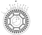
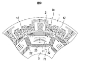
- FIG. 1 is a radial cross-sectional view of a composite torque rotating electric machine
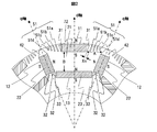
- FIG. 2 is an enlarged view of a main part of a rotor structure.
- the d-axis magnetic pole central axis by a permanent magnet
- the q-axis that is electromagnetically orthogonal to the d-axis are indicated by alternate long and short dash lines.
- the composite torque type rotating electric machine of this embodiment is constituted by a stator 1 having an 8-pole armature winding and a cylindrical rotor 3.
- the iron core of the rotor 3 is composed of laminated circular electromagnetic steel plates, and a permanent magnet composed of three or more ferrite magnets is embedded in one magnetic pole.
- a plurality of teeth 4 are formed on the stator 1 along the inner circumferential direction, and the armature winding 2 is wound around each tooth 4.
- a permanent magnet 21 having a circumferential direction as a longitudinal direction is disposed on the outer peripheral side of the rotor 3.
- the outer peripheral permanent magnet 21 is embedded in a substantially rectangular permanent magnet insertion cavity 11 formed on the outer peripheral side on the d-axis, and is fixed with an adhesive or resin rubber, and is parallel to the d-axis. It is magnetized in the direction.
- the permanent magnet insertion cavity 11 is longer than the permanent magnet 21 in the circumferential direction, and a substantially triangular or trapezoidal gap 31 is formed at both ends of the permanent magnet 21.
- the permanent magnet 22 is arranged on the rotor 3 so as to extend along the q axis.
- the permanent magnet 22 is embedded in a substantially rectangular permanent magnet insertion cavity 12 formed on the q axis, and is fixed with an adhesive or resin rubber.
- the permanent magnet 22 is magnetized in a direction orthogonal to the q axis, and when the outer peripheral surface of the permanent magnet 21 is an N pole, the surface facing the d axis in which the permanent magnet 21 is embedded is an N pole. It arrange
- a trapezoidal gap 42 is formed at the outer peripheral end of the permanent magnet 22, and a triangular or trapezoidal gap 32 is formed at the inner peripheral end.
- a permanent magnet 23 whose longitudinal direction is the circumferential direction is arranged on the inner peripheral side of the permanent magnet 21.
- the inner peripheral permanent magnet 23 is embedded in a rectangular permanent magnet insertion cavity 13 formed on the inner peripheral side of the d-axis, and is fixed with an adhesive or resin rubber.
- the permanent magnet 23 is magnetized in a direction parallel to the d-axis, and when the outer peripheral surface of the permanent magnet 21 is an N pole, the outer peripheral surface of the permanent magnet 23 is an N pole.
- the outer peripheral surface of the permanent magnet 21 is the south pole, the outer peripheral surface of the permanent magnet 23 is arranged to be the south pole.
- the permanent magnets 21 to 23 are arranged on each side of the trapezoid on the rotor 3.
- the distance A between the permanent magnet 21 located on the outer peripheral side on the d-axis of the rotor and the permanent magnet 22 on the q-axis and the trapezoidal gap 42 allows the armature magnetic flux from the stator to easily flow into the rotor.
- the distance B is set larger than the distance A, and the armature magnetic flux from the stator 1 can easily flow into the rotor 3. Can be made.
- FIG. 1 An example of the magnetization directions of the permanent magnets 21 to 23 is shown in FIG. That is, in the present embodiment, the permanent magnet 21 and the permanent magnet 23 are magnetized so that the outer peripheral side becomes the N pole and the inner peripheral side becomes the S pole, and the permanent magnet 22 is magnetized so that the N pole faces each other.
- a plurality of slits 51a to 51d constitute a slit group (slit part) 51 in the iron core part between the trapezoidal gap 42 located on the outer peripheral side of the permanent magnet 22 and the permanent magnet 21.
- a slit group (slit part) 51 in the iron core part between the trapezoidal gap 42 located on the outer peripheral side of the permanent magnet 22 and the permanent magnet 21.
- the trapezoidal gap 42 and the slit group 51 are non-magnetic bodies (non-magnetic body portions), and together with the permanent magnets 21 constitute a magnetic flux blocking portion.
- the slit group 51 is disposed on the outer peripheral side of the rotor 3, and more preferably on the outer periphery than a straight line connecting the inner peripheral side corner of the permanent magnet 21 and the center of the outer peripheral side of the trapezoidal gap 42. Formed on the side.
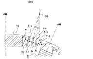
- Each of the slits 51a to 51d constituting the slit group 51 has an elongated shape that is narrow in the circumferential direction of the rotor 3 and extends in the radial direction, and a plurality of these are provided at intervals in the circumferential direction.
- These slits 51a to 51d may be arranged parallel to each other, but preferably, the slits are arranged radially so that the width between the slits is narrow on the outer peripheral side and wide on the inner peripheral side. .
- the radial arrangement is a slit group 51 as shown in FIG. That is, the slit 51a closest to the permanent magnet 21 is formed to be parallel to the q axis, and the slit 51d closest to the q axis is formed to be parallel to the d axis.
- the slits 51b and 51c are arranged radially by setting the angle around the intersection 55 between the central axis of the slit 51a and the central axis of the slit 51d to an angle that is divided into substantially equal angles.
- each slit is shortened at a certain rate from the d-axis side slit to the q-axis side slit. That is, the slit 51a is the longest, the slit 51d is the shortest, and the slits 51b and 51c between them are formed shorter in order.
- the circumferential direction position of the slit group 51 it forms in the approximate center between the permanent magnet 21 and the trapezoid-shaped space
- Each slit is filled with a non-magnetic material such as air or resin, and the non-magnetic material can increase the strength of the iron core.
- the first is the effect of the structure of the outer peripheral portion of the rotor 3.
- the permanent magnet 21 is disposed on the outer peripheral side of the rotor, and the air gap 31 is provided at both ends in the longitudinal direction of the permanent magnet 21.
- a slit group 51 exists adjacent to the slit group 51, and a gap 42 exists adjacent to the slit group 51.
- the slit group 51, the air gap 31, the permanent magnet 21, and these repeatedly exist over the entire circumferential direction. For this reason, the effect
- the second action is an action as a rectification means (guide means) by the slit group 51 of the armature magnetic flux generated by the stator winding 2. That is, the width between the slits is radially arranged so that the outer peripheral side interval is narrow and the inner peripheral side interval is widened, so that the magnetic flux is rectified after passing through the slit group 51 and then radially. It is guided so as to spread and flows while diffusing throughout the iron core portion 72 having a large area sandwiched between the permanent magnet 21 and the permanent magnet 23.
- the slit 51a is formed to be the longest, the magnetic flux passing through the iron cores on both sides of the slit is guided further in the direction along the slit 51a, so that the magnetic flux is not short-cut in the iron core portion 72. , Guided to spread throughout.
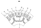
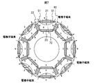
- Fig. 4 shows a conceptual diagram of the space harmonics of the armature magnetic flux.
- armature winding 2 When the armature winding 2 is energized, a closed loop armature magnetic flux is generated around the armature winding 2.
- this armature magnetic flux there is a magnetic flux that forms a closed loop around one slot, which flows into the rotor 3 from one tooth of the stator 1 and flows into the other nearest tooth.
- This is the space harmonic 61 of the armature magnetic flux, and since the cycle is different from the output torque, it does not contribute to the output torque.
- the spatial harmonic 61 causes magnetic saturation despite no contribution to the rotation of the electric motor, so that an effective amount of magnetic flux contributing to the torque cannot be obtained sufficiently, and it is necessary to suppress this. .
- FIG. 4 does not show the structure of this embodiment, the armature magnetic flux space harmonics 61 (indicated by solid arrows in the figure) are generated at a plurality of locations. Further, in FIG. 4, spatial harmonics (indicated by broken line arrows 62 in the figure) generated around the armature winding 2 located at the center are blocked by the permanent magnet 21.
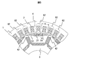
- FIG. 5 shows a conceptual diagram of the flow of spatial harmonics in the present embodiment.
- Spatial harmonics of the armature magnetic flux easily pass through a magnetic material such as an iron core, but are blocked by providing a non-magnetic material such as air or resin on the passing magnetic path.
- the spatial harmonics are blocked by arranging the permanent magnet 21, the slit group 51, and the trapezoidal gap 42 on the outer peripheral side of the rotor.
- the spatial harmonics form a closed loop with adjacent teeth. Therefore, the interval between the permanent magnet 21 and the trapezoidal gap 42, the interval between the permanent magnet 21 and the slit group 51, the interval between the slit group 51 and the trapezoidal gap 42, and the interval between the slits are adjacent to each other. By narrowing it less than the tooth interval (tooth pitch), the spatial harmonics 61 can be blocked efficiently.
- the arrangement of permanent magnets arranged on the outer peripheral side of the rotor 3 or nonmagnetic material portions such as air gaps is as follows. This makes it possible to block spatial harmonics.
- the distance between the permanent magnet and the non-magnetic part, the distance between the permanent magnet and the slit part, the distance between the slit part and the gap, and the distance Xn between the slits (where Xn is the nth distance)
- the maximum n is 6)
- the interval Y between the teeth 4 of the stator 1 is set smaller than X (Xn ⁇ Y).
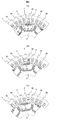
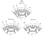
- 6A to 6C show the positional relationship between the rotor 3 and the stator teeth 4 at an arbitrary angle.
- at least the interval Xn is made narrower than the interval Y of the teeth, so that even if the positional relationship between the teeth of the stator and the rotor changes during operation, the permanent magnets 21, Since the slit group 51 and the trapezoidal gap 42 are present, spatial harmonics can be blocked at any position.
- the permanent magnet 21, the air gap 42, and the slit group 51 are sequentially arranged in the circumferential direction on the outer periphery side of the rotor, and each suppresses each spatial harmonic generated around the armature winding that does not contribute to torque. Plays.
- gap part, and a slit part (slit group) function as a magnetic flux shielding part, This cuts the unnecessary magnetic flux because this extends in the circumferential direction.
- the broken line 62 in FIGS. 6A to 6C it can be understood that the spatial harmonics are effectively blocked regardless of the rotational position of the rotor 3.
- the armature magnetic flux passing therethrough is increased without magnetic saturation in the iron core portion 72 having a large area sandwiched between the permanent magnet 21 and the permanent magnet 23.
- the reluctance torque can be increased by reducing the magnetic resistance.
- FIG. 8 is a diagram showing the flow of magnet magnetic flux of the permanent magnet.
- FIG. 9 is a diagram showing the magnetic flux distribution by the electromagnetic field analysis of the present embodiment, and is a conceptual diagram for explaining the operation of the slit group 51 described above.
- the present embodiment is provided with the slit group 51 when the reluctance torque is actively used to increase the output (see FIGS. 1 and 2). It can be confirmed that the slit group 51 functions as a rectifying means (guide means) that arranges and guides the flow of magnetic flux flowing in and out between the rotor 3 and the stator 1.
- the slit interval on the inner peripheral side is larger than the slit interval on the outer peripheral side so that the magnetic flux is rectified by the slit group 51 into a flow that diffuses throughout the iron core portion 72 sandwiched between the permanent magnet 21 and the permanent magnet 23. It has a large shape.
- the magnetic flux flows into the rotor 3 from the stator 1, it is divided by the trapezoidal gap 42 and the permanent magnet 22, and each divided magnetic flux 70 passes through the slit group 51 and spreads radially. 3 diffused throughout the wide core portion 72.
- the magnetic flux 71 diffused from the slit group 51 passes through the other slit group 51 and flows out of the rotor, but the magnetic flux diffused when passing through the one slit group 51 is rectified by the other slit group 51. Therefore, the saliency is not impaired.
- the distance B between the permanent magnet 21 and the permanent magnet 23 is wide, and the iron core portion 72 serving as a magnetic flux flow path is formed wide. Since the distance A between the end of 21 and the trapezoidal gap 42 is narrower than the distance B between the permanent magnet 21 and the permanent magnet 23, the magnetic flux flows from the narrow part of the slit group 51 to the wide part at the time of inflow. Since the magnetic flux is diffused and concentrated when it flows out, the flow of the magnetic flux can be effectively adjusted (see FIG. 2 for the distance A and the distance B). In addition to this, the flow of magnetic flux can be more effectively adjusted by the rectifying action of the magnetic flux by the slit group 51 described above.
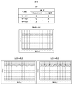
- FIG. 10 is a diagram showing an example of a comparison / examination model based on electromagnetic field analysis.
- Case 1 in FIG. 10A has the structure of the present embodiment already described.
- case 2 of FIG. 10B all slits formed between the permanent magnet 21 and the trapezoidal gap 42 are formed in parallel with the q axis, and the radial length is the same.
- Case 3 in FIG. 10C is a comparative example in which the slit group 51 is not provided and the shape of the gap 43 on the outer peripheral side of the permanent magnet 22 is rectangular.
- FIG. 11 shows a determination table (a) of average output torque and torque pulsation by electromagnetic field analysis in each case of FIG. 10, and torque waveforms at that time are shown in (b) to (d).
- the average output torque sufficient torque is obtained in case 1 and case 2, but in case 3 it is reduced by about 5% compared to case 1 or case 2.
- Case 1 is the best at about 5%, and Case 2 is 10% or less. In case 3, it is 20% or more. In a reluctance type rotating electrical machine using reluctance torque, the torque pulsation is generally about 20%. Therefore, the slit group 51 formed in the case 1 and the case 2 and the trapezoidal gap 42 are very large. It can be seen that this is effective.
- each of the slits of this embodiment has the following configuration. Is desirable. (1) It extends long in the direction along the radial direction. (2) The rotor should be arranged so as to expand from the outer peripheral side to the inner peripheral side. In (1), it can be confirmed that it greatly contributes to the rectifying action of the magnetic flux (see cases 1 and 2 in FIGS.
- the structure has a structure that can sufficiently obtain the effect of reducing torque pulsation. Further, by using the slit arrangement as shown in (2), it is possible to further reduce the torque pulsation (see case 1 in FIGS. 10 and 11), and a more preferable configuration can be realized.
- a permanent magnet is embedded on the outer peripheral side on the d-axis
- a trapezoidal gap is formed on the permanent magnet on the q-axis and the outer peripheral side end
- the permanent magnet and trapezoid on the outer peripheral side on the d-axis are formed.
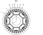
- FIG. 12 is a radial cross-sectional view of a composite torque type rotary electric machine according to Embodiment 2 of the present invention
- FIG. 13 is an enlarged view of a main part thereof.
- 12 and 13 includes a stator 1 having an 8-pole armature winding, and a cylindrical rotor 3.
- the iron core of the rotor 3 of the structure of this embodiment is composed of laminated circular electromagnetic steel plates, and three or more permanent magnets are embedded in one magnetic pole.
- a slit group 52 is provided.
- the permanent magnet 22 is embedded in the rectangular gap 12 on the q axis and fixed with an adhesive or resin rubber.
- a trapezoidal gap 42 is formed at the outer peripheral end of the permanent magnet 22.
- a substantially triangular or substantially trapezoidal gap 32 is provided at the end on the inner peripheral side.
- the permanent magnet 23 is embedded in the rectangular gap 13 on the inner peripheral side on the d-axis, and is fixed with an adhesive or resin rubber.
- the permanent magnet 23 is magnetized in a direction parallel to the d-axis.
- the outer peripheral surface of the permanent magnet 23 is an N pole.
- the outer peripheral surface of the permanent magnet 23 is disposed so as to be the south pole.
- a slit group 51 including a plurality of slits is formed in the iron core between the slit group 52 and the trapezoidal gap 42 located on the outer peripheral side of the permanent magnet 22.
- four slits are shown as in the first embodiment, but it is obvious that the present invention is not limited to this.
- the slit 51a closest to the slit group 52 is formed so as to be parallel to the q axis (close q axis), and the slit 51d closest to the q axis is formed so as to be parallel to the d axis.
- the slits 51b and 51c are distributed at substantially equal angles around the intersection of the central axis of the slit 51a and the central axis of the slit 51d (see FIG. 3).
- the length of each slit in the slit group 51 is reduced from the d-axis side slit to the q-axis side slit at a constant rate.
- About the circumferential direction position of the slit group 51 it forms in the approximate center between the slit group 52 and the trapezoid gap 42.
- Each slit is filled with a non-magnetic material such as air or resin.
- the slit group 52 formed on the outer diameter side on the d-axis is composed of a plurality of parallel slits, and constitutes a magnetic shielding portion similar to the permanent magnet 21 of the first embodiment, and the armature winding of the stator 1 2 acts to block the spatial harmonics 61 of the armature magnetic flux generated in 2 and the same effect as the structure shown in the first embodiment is obtained.
Landscapes
- Engineering & Computer Science (AREA)
- Power Engineering (AREA)
- Permanent Field Magnets Of Synchronous Machinery (AREA)
- Iron Core Of Rotating Electric Machines (AREA)
- Permanent Magnet Type Synchronous Machine (AREA)
Abstract
Priority Applications (6)
| Application Number | Priority Date | Filing Date | Title |
|---|---|---|---|
| CN201280069328.8A CN104106198B (zh) | 2012-05-28 | 2012-05-28 | 复合转矩型旋转电机 |
| DE112012005674.4T DE112012005674T5 (de) | 2012-05-28 | 2012-05-28 | Drehende elektrische Maschine mit kombiniertem Drehmoment |
| US14/404,416 US9853509B2 (en) | 2012-05-28 | 2012-05-28 | Composite torque rotating electric machine |
| JP2014518112A JP6002217B2 (ja) | 2012-05-28 | 2012-05-28 | 複合トルク型回転電機 |
| PCT/JP2012/063672 WO2013179375A1 (fr) | 2012-05-28 | 2012-05-28 | Machine électrique rotative à couple composite |
| TW102105881A TWI477035B (zh) | 2012-05-28 | 2013-02-20 | Compound Torque Rotary Motor |
Applications Claiming Priority (1)
| Application Number | Priority Date | Filing Date | Title |
|---|---|---|---|
| PCT/JP2012/063672 WO2013179375A1 (fr) | 2012-05-28 | 2012-05-28 | Machine électrique rotative à couple composite |
Publications (1)
| Publication Number | Publication Date |
|---|---|
| WO2013179375A1 true WO2013179375A1 (fr) | 2013-12-05 |
Family
ID=49672629
Family Applications (1)
| Application Number | Title | Priority Date | Filing Date |
|---|---|---|---|
| PCT/JP2012/063672 WO2013179375A1 (fr) | 2012-05-28 | 2012-05-28 | Machine électrique rotative à couple composite |
Country Status (6)
| Country | Link |
|---|---|
| US (1) | US9853509B2 (fr) |
| JP (1) | JP6002217B2 (fr) |
| CN (1) | CN104106198B (fr) |
| DE (1) | DE112012005674T5 (fr) |
| TW (1) | TWI477035B (fr) |
| WO (1) | WO2013179375A1 (fr) |
Cited By (2)
| Publication number | Priority date | Publication date | Assignee | Title |
|---|---|---|---|---|
| WO2015186280A1 (fr) * | 2014-06-02 | 2015-12-10 | パナソニックIpマネジメント株式会社 | Moteur électrique à aimants permanents encastrés |
| JP7415871B2 (ja) | 2020-10-22 | 2024-01-17 | トヨタ自動車株式会社 | 回転電機 |
Families Citing this family (28)
| Publication number | Priority date | Publication date | Assignee | Title |
|---|---|---|---|---|
| CN105745820B (zh) * | 2013-11-20 | 2018-11-16 | 日立汽车系统株式会社 | 旋转电机和具备该旋转电机的电动车辆 |
| CN104852493A (zh) * | 2015-04-29 | 2015-08-19 | 华域汽车电动系统有限公司 | 一种内置式永磁同步电机转子 |
| KR102504423B1 (ko) * | 2015-05-27 | 2023-02-28 | 엘지이노텍 주식회사 | 로터 및 이를 포함하는 모터 |
| US11139707B2 (en) | 2015-08-11 | 2021-10-05 | Genesis Robotics And Motion Technologies Canada, Ulc | Axial gap electric machine with permanent magnets arranged between posts |
| US9755463B2 (en) | 2015-08-11 | 2017-09-05 | Genesis Robotics Llp | Electric machine |
| KR102491659B1 (ko) * | 2015-10-08 | 2023-01-26 | 삼성전자주식회사 | 영구자석 내측 배치형 비엘디씨 모터 |
| KR101936159B1 (ko) * | 2016-05-17 | 2019-04-03 | 한국건설기술연구원 | 공기간극형 막증류 모듈을 이용한 해수담수화 시스템 및 그 방법 |
| US11043885B2 (en) | 2016-07-15 | 2021-06-22 | Genesis Robotics And Motion Technologies Canada, Ulc | Rotary actuator |
| CN106300742A (zh) * | 2016-10-19 | 2017-01-04 | 江苏航天动力机电有限公司 | 新能源三相异步启动永磁同步电动机转子冲片 |
| JP6802087B2 (ja) * | 2017-02-23 | 2020-12-16 | ファナック株式会社 | ロータ |
| US10749385B2 (en) * | 2017-05-18 | 2020-08-18 | General Electric Company | Dual magnetic phase material rings for AC electric machines |
| US10715017B2 (en) * | 2017-06-02 | 2020-07-14 | Hamilton Sundstrand Corporation | Hybrid synchronous machines |
| US11843334B2 (en) | 2017-07-13 | 2023-12-12 | Denso Corporation | Rotating electrical machine |
| CN113972806B (zh) | 2017-07-21 | 2023-10-31 | 株式会社电装 | 旋转电机 |
| JP6922868B2 (ja) * | 2017-12-28 | 2021-08-18 | 株式会社デンソー | 回転電機システム |
| CN111557069A (zh) | 2017-12-28 | 2020-08-18 | 株式会社电装 | 旋转电机 |
| JP7006541B2 (ja) | 2017-12-28 | 2022-01-24 | 株式会社デンソー | 回転電機 |
| DE112018006694T5 (de) | 2017-12-28 | 2020-09-10 | Denso Corporation | Rotierende elektrische Maschine |
| CN111566904B (zh) | 2017-12-28 | 2023-04-28 | 株式会社电装 | 旋转电机 |
| US11799337B2 (en) * | 2018-07-19 | 2023-10-24 | Mitsubishi Electric Corporation | Rotating electric machine |
| US20200083767A1 (en) * | 2018-09-06 | 2020-03-12 | Adlee Powertronic Co., Ltd. | Permanent magnet motor |
| US11581767B2 (en) * | 2018-09-06 | 2023-02-14 | Adlee Powertronic Co., Ltd. | Permanent magnet motor |
| US10797546B2 (en) * | 2019-01-08 | 2020-10-06 | Borgwarner Inc. | Interior permanent magnet electric machine with flux distributing voids |
| CN113692690A (zh) | 2020-03-05 | 2021-11-23 | 株式会社电装 | 旋转电机 |
| CN112803637A (zh) * | 2021-01-14 | 2021-05-14 | 南京理工大学 | 一种永磁同步电机及其聚磁转子结构 |
| US11926880B2 (en) | 2021-04-21 | 2024-03-12 | General Electric Company | Fabrication method for a component having magnetic and non-magnetic dual phases |
| US11661646B2 (en) | 2021-04-21 | 2023-05-30 | General Electric Comapny | Dual phase magnetic material component and method of its formation |
| CN114301203B (zh) * | 2021-12-29 | 2023-03-14 | 东南大学 | 一种高转矩密度磁路串联型转子结构 |
Citations (3)
| Publication number | Priority date | Publication date | Assignee | Title |
|---|---|---|---|---|
| JP2001145283A (ja) * | 1999-11-19 | 2001-05-25 | Toyota Motor Corp | 永久磁石式回転機の回転子 |
| JP2001178092A (ja) * | 1999-10-06 | 2001-06-29 | Asmo Co Ltd | リラクタンス型電動機 |
| JP2006081338A (ja) * | 2004-09-10 | 2006-03-23 | Nissan Motor Co Ltd | 回転電機のロータ |
Family Cites Families (17)
| Publication number | Priority date | Publication date | Assignee | Title |
|---|---|---|---|---|
| FR2548843B1 (fr) * | 1983-07-07 | 1986-11-07 | Labinal | Perfectionnement aux machines tournantes a aimants au rotor |
| JP3290392B2 (ja) | 1997-10-31 | 2002-06-10 | 株式会社東芝 | 永久磁石式リラクタンス型回転電機 |
| JP3970392B2 (ja) | 1997-10-13 | 2007-09-05 | 松下電器産業株式会社 | 永久磁石埋め込み回転子 |
| US6483212B1 (en) | 1999-10-06 | 2002-11-19 | Asmo Co., Ltd. | Reluctance-type electric motor |
| JP2002354730A (ja) * | 2001-05-25 | 2002-12-06 | Hitachi Ltd | 永久磁石式回転電機 |
| DE10256523A1 (de) * | 2002-12-04 | 2004-06-24 | Robert Bosch Gmbh | Elektrische Maschine, insbesondere bürstenloser Synchronmotor |
| JP4248984B2 (ja) * | 2003-09-19 | 2009-04-02 | 東芝キヤリア株式会社 | 永久磁石電動機 |
| JP4449035B2 (ja) * | 2004-03-10 | 2010-04-14 | 日立オートモティブシステムズ株式会社 | 電動車両用の永久磁石回転電機 |
| JP5016852B2 (ja) * | 2006-06-09 | 2012-09-05 | 日立アプライアンス株式会社 | 永久磁石電動機,永久磁石同期電動機の回転子及びそれを用いた圧縮機 |
| JP5259934B2 (ja) * | 2006-07-20 | 2013-08-07 | 株式会社日立産機システム | 永久磁石式回転電機及びそれを用いた圧縮機 |
| CN102170212B (zh) * | 2006-08-23 | 2012-07-18 | 株式会社东芝 | 永久磁铁式旋转电机 |
| JP2008167520A (ja) * | 2006-12-27 | 2008-07-17 | Toyota Central R&D Labs Inc | 回転電機 |
| JP4466671B2 (ja) * | 2007-03-28 | 2010-05-26 | 株式会社日立製作所 | 誘導機 |
| JP4672030B2 (ja) * | 2008-01-31 | 2011-04-20 | 日立オートモティブシステムズ株式会社 | 焼結磁石及びそれを用いた回転機 |
| JP2010158085A (ja) * | 2008-12-26 | 2010-07-15 | Mitsubishi Electric Corp | 永久磁石型モータの回転子 |
| DE102009050991A1 (de) * | 2009-10-28 | 2011-05-05 | Bayerische Motoren Werke Aktiengesellschaft | Elektrische Antriebsmaschine für ein Fahrzeug |
| JP2012080697A (ja) * | 2010-10-04 | 2012-04-19 | Asmo Co Ltd | モータ |
-
2012
- 2012-05-28 DE DE112012005674.4T patent/DE112012005674T5/de not_active Withdrawn
- 2012-05-28 US US14/404,416 patent/US9853509B2/en not_active Expired - Fee Related
- 2012-05-28 CN CN201280069328.8A patent/CN104106198B/zh not_active Expired - Fee Related
- 2012-05-28 WO PCT/JP2012/063672 patent/WO2013179375A1/fr active Application Filing
- 2012-05-28 JP JP2014518112A patent/JP6002217B2/ja not_active Expired - Fee Related
-
2013
- 2013-02-20 TW TW102105881A patent/TWI477035B/zh not_active IP Right Cessation
Patent Citations (3)
| Publication number | Priority date | Publication date | Assignee | Title |
|---|---|---|---|---|
| JP2001178092A (ja) * | 1999-10-06 | 2001-06-29 | Asmo Co Ltd | リラクタンス型電動機 |
| JP2001145283A (ja) * | 1999-11-19 | 2001-05-25 | Toyota Motor Corp | 永久磁石式回転機の回転子 |
| JP2006081338A (ja) * | 2004-09-10 | 2006-03-23 | Nissan Motor Co Ltd | 回転電機のロータ |
Cited By (2)
| Publication number | Priority date | Publication date | Assignee | Title |
|---|---|---|---|---|
| WO2015186280A1 (fr) * | 2014-06-02 | 2015-12-10 | パナソニックIpマネジメント株式会社 | Moteur électrique à aimants permanents encastrés |
| JP7415871B2 (ja) | 2020-10-22 | 2024-01-17 | トヨタ自動車株式会社 | 回転電機 |
Also Published As
| Publication number | Publication date |
|---|---|
| TW201349712A (zh) | 2013-12-01 |
| TWI477035B (zh) | 2015-03-11 |
| US9853509B2 (en) | 2017-12-26 |
| JPWO2013179375A1 (ja) | 2016-01-14 |
| CN104106198B (zh) | 2017-11-07 |
| US20150171682A1 (en) | 2015-06-18 |
| DE112012005674T5 (de) | 2014-10-09 |
| JP6002217B2 (ja) | 2016-10-05 |
| CN104106198A (zh) | 2014-10-15 |
Similar Documents
| Publication | Publication Date | Title |
|---|---|---|
| JP6002217B2 (ja) | 複合トルク型回転電機 | |
| JP5876147B2 (ja) | 複合トルク型回転電機 | |
| JP5328821B2 (ja) | 回転電機用回転子 | |
| CN112838693B (zh) | 旋转电机 | |
| JP5643127B2 (ja) | 回転電機用回転子 | |
| JP5709907B2 (ja) | 車両用永久磁石埋込型回転電機 | |
| JP6033425B2 (ja) | 可変磁束型回転電機 | |
| JP6421926B2 (ja) | 永久磁石同期機 | |
| JP2019062673A (ja) | 可変磁束型の永久磁石式回転電機 | |
| JP2013055872A (ja) | スイッチドリラクタンスモータ | |
| US9337692B2 (en) | Permanent magnet rotor with flux barrier for reduced demagnetization | |
| JP7076188B2 (ja) | 可変磁力モータ | |
| JP2008148391A (ja) | 回転電機の回転子及び回転電機 | |
| JP2013132124A (ja) | 界磁子用コア | |
| JP7299531B2 (ja) | 回転子、モータ | |
| JP2015061328A (ja) | 回転電機のロータ | |
| JP6440349B2 (ja) | 回転電機 | |
| JPWO2017212575A1 (ja) | 永久磁石モータ | |
| JP5750995B2 (ja) | 同期電動機 | |
| JP5793948B2 (ja) | 同期電動機 | |
| WO2022114176A1 (fr) | Moteur électrique | |
| JP6398266B2 (ja) | 埋込磁石型回転電機 | |
| JP2021145420A (ja) | 永久磁石同期モータ | |
| JP2017169314A (ja) | 永久磁石埋込同期機 |
Legal Events
| Date | Code | Title | Description |
|---|---|---|---|
| 121 | Ep: the epo has been informed by wipo that ep was designated in this application |
Ref document number: 12877752 Country of ref document: EP Kind code of ref document: A1 |
|
| ENP | Entry into the national phase |
Ref document number: 2014518112 Country of ref document: JP Kind code of ref document: A |
|
| WWE | Wipo information: entry into national phase |
Ref document number: 1120120056744 Country of ref document: DE Ref document number: 112012005674 Country of ref document: DE |
|
| WWE | Wipo information: entry into national phase |
Ref document number: 14404416 Country of ref document: US |
|
| 122 | Ep: pct application non-entry in european phase |
Ref document number: 12877752 Country of ref document: EP Kind code of ref document: A1 |