WO2013161252A1 - Machine à laver à tambour - Google Patents
Machine à laver à tambour Download PDFInfo
- Publication number
- WO2013161252A1 WO2013161252A1 PCT/JP2013/002678 JP2013002678W WO2013161252A1 WO 2013161252 A1 WO2013161252 A1 WO 2013161252A1 JP 2013002678 W JP2013002678 W JP 2013002678W WO 2013161252 A1 WO2013161252 A1 WO 2013161252A1
- Authority
- WO
- WIPO (PCT)
- Prior art keywords
- drum
- laundry
- rolling element
- washing machine
- eccentric
- Prior art date
Links
Images


Classifications
-
- D—TEXTILES; PAPER
- D06—TREATMENT OF TEXTILES OR THE LIKE; LAUNDERING; FLEXIBLE MATERIALS NOT OTHERWISE PROVIDED FOR
- D06F—LAUNDERING, DRYING, IRONING, PRESSING OR FOLDING TEXTILE ARTICLES
- D06F37/00—Details specific to washing machines covered by groups D06F21/00 - D06F25/00
- D06F37/20—Mountings, e.g. resilient mountings, for the rotary receptacle, motor, tub or casing; Preventing or damping vibrations
- D06F37/22—Mountings, e.g. resilient mountings, for the rotary receptacle, motor, tub or casing; Preventing or damping vibrations in machines with a receptacle rotating or oscillating about a horizontal axis
- D06F37/225—Damping vibrations by displacing, supplying or ejecting a material, e.g. liquid, into or from counterbalancing pockets
-
- D—TEXTILES; PAPER
- D06—TREATMENT OF TEXTILES OR THE LIKE; LAUNDERING; FLEXIBLE MATERIALS NOT OTHERWISE PROVIDED FOR
- D06F—LAUNDERING, DRYING, IRONING, PRESSING OR FOLDING TEXTILE ARTICLES
- D06F33/00—Control of operations performed in washing machines or washer-dryers
-
- D—TEXTILES; PAPER
- D06—TREATMENT OF TEXTILES OR THE LIKE; LAUNDERING; FLEXIBLE MATERIALS NOT OTHERWISE PROVIDED FOR
- D06F—LAUNDERING, DRYING, IRONING, PRESSING OR FOLDING TEXTILE ARTICLES
- D06F33/00—Control of operations performed in washing machines or washer-dryers
- D06F33/30—Control of washing machines characterised by the purpose or target of the control
- D06F33/48—Preventing or reducing imbalance or noise
-
- D—TEXTILES; PAPER
- D06—TREATMENT OF TEXTILES OR THE LIKE; LAUNDERING; FLEXIBLE MATERIALS NOT OTHERWISE PROVIDED FOR
- D06F—LAUNDERING, DRYING, IRONING, PRESSING OR FOLDING TEXTILE ARTICLES
- D06F37/00—Details specific to washing machines covered by groups D06F21/00 - D06F25/00
- D06F37/02—Rotary receptacles, e.g. drums
- D06F37/04—Rotary receptacles, e.g. drums adapted for rotation or oscillation about a horizontal or inclined axis
-
- D—TEXTILES; PAPER
- D06—TREATMENT OF TEXTILES OR THE LIKE; LAUNDERING; FLEXIBLE MATERIALS NOT OTHERWISE PROVIDED FOR
- D06F—LAUNDERING, DRYING, IRONING, PRESSING OR FOLDING TEXTILE ARTICLES
- D06F2103/00—Parameters monitored or detected for the control of domestic laundry washing machines, washer-dryers or laundry dryers
- D06F2103/26—Unbalance; Noise level
-
- D—TEXTILES; PAPER
- D06—TREATMENT OF TEXTILES OR THE LIKE; LAUNDERING; FLEXIBLE MATERIALS NOT OTHERWISE PROVIDED FOR
- D06F—LAUNDERING, DRYING, IRONING, PRESSING OR FOLDING TEXTILE ARTICLES
- D06F2105/00—Systems or parameters controlled or affected by the control systems of washing machines, washer-dryers or laundry dryers
- D06F2105/46—Drum speed; Actuation of motors, e.g. starting or interrupting
- D06F2105/48—Drum speed
-
- D—TEXTILES; PAPER
- D06—TREATMENT OF TEXTILES OR THE LIKE; LAUNDERING; FLEXIBLE MATERIALS NOT OTHERWISE PROVIDED FOR
- D06F—LAUNDERING, DRYING, IRONING, PRESSING OR FOLDING TEXTILE ARTICLES
- D06F34/00—Details of control systems for washing machines, washer-dryers or laundry dryers
- D06F34/14—Arrangements for detecting or measuring specific parameters
- D06F34/16—Imbalance
Definitions
- the present invention relates to a drum-type washing machine having a drum that can be rotated by accommodating laundry in an elastically supported water tub, and washing, rinsing, and dewatering the laundry in the drum.
- the ball balancer includes a plurality of balls having degrees of freedom in the rotation direction (circumferential direction) in an annular container portion attached to the inner periphery of the drum.
- the ball balancer is a balance device that utilizes a dynamic phenomenon in which a ball automatically moves to an opposing position with respect to an unbalanced body that generates an eccentric load.
- Patent Document 1 In addition to a single ball balancer in which a ball balancer is disposed only on the opening side of the drum, a double ball balancer in which ball balancers are disposed at two locations on the opening side and bottom side of the drum is also known (for example, Patent Document 1).
- FIG. 9 is a view showing a conventional drum-type washing machine.
- An annular container 102 is provided on the opening side and the bottom surface side of the drum 101, and a rolling element 103 made of a metal sphere is movably included in each annular container 102 to constitute a ball balancer 104.
- These ball balancers 104 are in principle the same as single ball balancers. That is, in both ball balancers 104, the plurality of rolling elements 103 change their positions and automatically correct the unbalance in response to the unbalance amount of the laundry that changes over time in the dehydration process.
- the drum 101 is rotated at a rotation speed equal to or lower than the resonance rotation speed, and the rolling element 103 moves to the in-phase position with respect to the eccentric load for a predetermined time, and maintains the in-phase position state. . Thereafter, the rotational speed of the drum 101 is gently accelerated to pass through the resonant rotational speed. Thereby, the rolling element 103 is automatically moved to the unbalanced opposing position by the principle of automatic balancing, thereby suppressing vibration.
- the rolling element 103 is in the same phase as the laundry unbalance in a state where the rotation speed of the drum 101 is lower than the resonance rotation speed. For this reason, since the rolling element 103 works as an imbalance with the laundry, there is a problem that vibration may increase when passing through the resonance rotational speed.
- the rolling element 103 for canceling the unbalance has a problem that it causes the unbalance.
- the drum-type washing machine of the present invention is integrally formed with a bottomed cylindrical drum rotatably supported by a horizontal or inclined rotating shaft, a water tank that accommodates the drum, a drive motor that drives the drum, and the drum.
- An annular container provided and a plurality of rolling elements movably accommodated inside the annular container.
- an eccentricity detection unit that detects the eccentricity of the laundry in the drum and the eccentric state of the drum caused by the rolling elements
- a control unit that analyzes the eccentric position detected by the eccentricity detection unit and controls the drive motor With. Then, the control unit detects the eccentric state of the drum by the eccentricity detection unit in a state where the laundry in the drum does not fall and the drum is rotated at a rotation speed at which the rolling element stays at the lower part of the drum.
- the drum-type washing machine of the present invention can start up the rotation of the drum so that the rolling elements can obtain a vibration suppressing effect against the unbalance of the laundry, so that the vibration of the drum at the resonance rotational speed can be increased. It can be minimized.
- the controller accelerates the drum after analyzing the eccentric position of the laundry, and the eccentric position of the rolling element and the laundry is opposed at a rotational speed lower than the resonant rotational speed.
- the drive motor is controlled so that the drum and the rolling element rotate together.
- control unit analyzes the eccentric position of the laundry, and accelerates the drum when the eccentric position of the laundry is above the rotation axis.
- FIG. 1 is a configuration diagram of a drum-type washing machine according to the first embodiment of the present invention.
- FIG. 2 is a schematic view of the ball balancer of the drum type washing machine according to the first embodiment of the present invention.
- FIG. 3 is a control block diagram of the drum type washing machine in the first embodiment of the present invention.
- FIG. 4 is a diagram illustrating a rotation speed sequence of the drum-type washing machine according to the first embodiment of the present invention.
- FIG. 5 is a characteristic diagram of the drive motor current of the drum type washing machine in the first embodiment of the present invention.
- FIG. 6A is a characteristic diagram of a drive motor current of the drum type washing machine in the first embodiment of the present invention.
- FIG. 1 is a configuration diagram of a drum-type washing machine according to the first embodiment of the present invention.
- FIG. 2 is a schematic view of the ball balancer of the drum type washing machine according to the first embodiment of the present invention.
- FIG. 3 is a control block diagram of the drum type washing machine
- FIG. 6B is a characteristic diagram of a drive motor current of the drum type washing machine in the first embodiment of the present invention.
- FIG. 7 is a diagram showing a rotation speed sequence of the drum-type washing machine according to the third embodiment of the present invention.
- FIG. 8 is a diagram showing a rotation speed sequence of the drum type washing machine in the fourth embodiment of the present invention.
- FIG. 9 is a configuration diagram of a conventional drum-type washing machine.
- FIG. 1 is a configuration diagram of a drum-type washing machine according to the first embodiment of the present invention.
- FIG. 2 is a schematic diagram of the ball balancer according to the first embodiment of the present invention.
- a cylindrical water tank 2 with a bottom is accommodated inside the drum-type washing machine 1.
- a bottomed cylindrical drum 3 is accommodated in the water tank 2.
- the drum 3 is disposed such that a rotating shaft 31 that rotatably supports the drum 3 is inclined downward from the front side toward the back side.
- the water tank 2 is inclined and arranged along the drum 3 with the opening 2a as the front side.
- the rotating shaft 31 by tilting the rotating shaft 31, compared to when the rotating shaft 31 is set in the horizontal direction, water supplied into the water tank 2 is accumulated on the back side, and deep water can be stored even with a small amount of water. That is, the laundry 13 can be easily hydrated even with a small amount of water supply.
- the water tank 2 is supported by a spring 10 and a damper 5.
- the rotating shaft 31 may be horizontal.
- a triangular columnar baffle 16 that lifts and drops the laundry 13 as the drum 3 rotates.
- the drum 3 is driven to rotate, the laundry 13 lifted by the baffle 16 is struck against the water surface from the top of the drum 3 and is washed by tapping (mechanical force).
- the drum 3 is provided with a plurality of through holes 15. Water can be passed from the water tank 2 into the drum 3 through the through holes 15.
- a door 7 is provided in the opening 3a so as to be freely opened and closed.
- the opening 2a of the water tank 2 is provided with an annular sealing material (not shown) at its mouth edge.
- the front side of the sealing material is in contact with the back side of the door 7 and sealed, and even if the opening 2a of the water tank 2 that swings up and down, right and left and back and forth moves, the sealing material is deformed and pressed against the back side of the door 7 Sex is maintained.
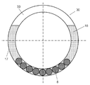
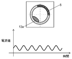
- a ball balancer (balancing part) 30 is provided in the opening 3 a on the front side of the drum 3.
- the ball balancer 30 includes an annular container 17 disposed on the front side of the drum 3, a rolling element 8 composed of a metal ball that can move in the annular container 17, and a viscous fluid 18 that is stored in the annular container 17. And a gas layer 33 (air).
- the ring-shaped annular container 17 is installed so as to be concentric with the drum 3. That is, the rotation axis of the annular container 17 coincides with the rotation axis of the rotation shaft 31.
- a viscous fluid 18 is stored inside the annular container 17.
- silicon oil is used as the viscous fluid 18.
- the viscous fluid 18 used in the present embodiment is not limited to silicon oil because the same effect can be obtained even with viscous liquids such as machine oil and other aqueous solutions.
- a driving motor 4 for rotating the drum 3 is attached to the inside of the drum type washing machine 1 below the water tank 2.
- the rotational drive of the drive motor 4 is transmitted to the drum pulley 24 connected to the rotary shaft 31 of the drum 3 via the belt 23.
- the drive motor 4 drives the drum 3 to rotate.
- the belt driving motor is described.
- a direct motor system that directly drives the drum 3 may be used.
- a water supply valve 11 is provided at the top of the drum type washing machine 1. Water from the water supply valve 11 flows into the detergent case 9 and is supplied into the water tank 2 while dissolving the detergent. In the rinsing process, since there is no detergent in the detergent case 9 even through the detergent case 9, rinsing water containing no detergent component is supplied.
- a drainage pump 19 is provided at the lower part of the drum-type washing machine 1 together with the drainage pipe 14. By driving the drainage pump 19, the washing water and the rinsing water in the water tank 2 are passed through the drainage pipe 14. Drained. In this embodiment, the drainage pump 19 drains the washing water and the rinsing water in the water tank 2, but a drainage valve may be provided instead of the drainage pump 19.
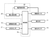
- FIG. 3 is a control block diagram of the drum type washing machine in the present embodiment.
- the control device 6 includes a control unit 6a, an eccentricity detection unit 20, and a current detection unit 22.
- the control unit 6 a instructs to drive the water supply valve 11, the drain pump 19, and the drive motor 4.
- the control unit 6a includes a system that can manage all input / output control including various sensor outputs such as the vibration detection unit 12 and the water level sensor 21 with a timer, and can know the time required for each operation and timing. .
- the control unit 6a is an electric circuit including a CPU, a memory, a driver circuit, and the like as a hardware configuration, and moves peripheral devices such as the drive motor 4 in accordance with a program stored in the memory in the control unit 6a.
- the current detection unit 22 detects the value and phase of the current applied to the drive motor 4 and outputs a signal to the eccentricity detection unit 20.
- the eccentricity detection unit 20 functions as an eccentric position detection unit that detects the eccentricity of the laundry and the eccentric position of the drum 3 caused by the rolling elements 8 based on the signal of the current detection unit. Furthermore, the eccentricity detection unit 20 also functions as an eccentricity detection unit that detects the amount of eccentricity of the drum 3 by comparing the magnitude of the current applied to the drive motor 4. That is, the control unit 6a can obtain the eccentric amount and the eccentric position of the drum 3 based on the current value and the phase detected by the eccentricity detection unit 20. The control unit 6a determines the eccentric position and the eccentric amount due to the laundry 13 and the position of the rolling element 8, and issues a command to the drive motor 4 to start up the rotation of the drum 3.
- the vibration detection unit 12 that detects the vibration of the water tank 2 is provided at the upper part on the back side of the water tank 2.
- the vibration detection unit 12 detects vibration of the water tank 2 in a series of steps of washing, rinsing, and dehydration. After the control unit 6a analyzes the vibration value in each step, the motor is optimally controlled by issuing a command to the drive motor 4.
- the vibration detection unit 12 includes at least one acceleration sensor, and detects vibration in at least one of the vertical direction, the horizontal direction, and the front-rear direction of the water tank 2.
- the acceleration sensor may be a semiconductor acceleration sensor, a piezoelectric acceleration sensor, or the like, and may be a uniaxial or biaxial acceleration sensor.
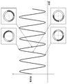
- FIG. 4 is a diagram showing a rotation speed sequence of the drum-type washing machine according to the present embodiment.
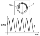
- 5, 6A and 6B are characteristic diagrams of the drive motor current in the present embodiment.
- the dehydration operation does not mean only final dehydration in the dehydration process, but also includes intermediate dehydration performed after the washing process or after the first rinsing process.
- a drive voltage is applied to the drive motor 4 according to a command from the control unit 6a.
- the drive motor 4 is operated from low speed rotation to high speed rotation, and the rotation speed of the drum 3 is gradually increased.
- the drive motor 4 is a permanent magnet synchronous motor, the rotor position of the drive motor 4 is detected. Thereby, it is possible to increase the rotational speed safely and at high speed by preventing the drive motor 4 from stepping out.
- the controller 6a increases and maintains the rotational speed of the drum 3 to a rotational speed at which the gravity applied to the laundry 13 and the rolling element 8 is smaller than the centrifugal force due to the rotation of the drum 3 ((1) in FIG. 4).
- the laundry 13 sticks to the inner wall of the drum 3.
- the rotational speed of the drum 3 at this time is slightly moved along the rotational direction of the drum 3 in such a manner that the rolling element 8 in the annular container 17 is dragged by the viscous fluid 18 in the annular container 17. 3, and a rotation speed that remains at a fixed position in the annular container 17 without rotating together.
- the following conditions are required at the drum rotation speed to which the laundry 13 is stuck. That is, the self-weight determined by the density, diameter, and number of the rolling elements 8, the viscous resistance force when the viscous fluid 18 passes through the gap between the rolling elements 8 and the inner surface of the annular container 17, and the rolling elements 8 and the annular container 17 The frictional force is balanced. Further, since the influence of centrifugal force increases as the rotational speed of the drum 3 increases, the rolling element 8 rotates together with the drum 3. When the rolling element 8 rotates together with the drum 3, the eccentricity 13 a caused by the rolling element 8 and the laundry 13 becomes a fluctuation factor of the current of the drive motor 4.
- the laundry 13 is rotating, and therefore the laundry is detected from the current value applied to the drive motor 4 detected by the current detection unit 22 or the amount of fluctuation of the current value. 13 eccentric amounts can be determined. Further, the unbalance position of the laundry 13 can be determined from the torque fluctuation (phase).
- the laundry 13 sticks to the inner wall to generate an eccentric 13 a (unbalance), and the drum 3 rotates once ( It is possible to detect the eccentric position and the eccentric amount due to the deviation of the laundry 13 within one cycle.
- the rotation speed is set to 80 rpm at which the bias of the laundry 13 can be easily confirmed.
- the controller 6 a determines the eccentric position of the drum 3 at this time, that is, the eccentric position and the eccentric amount of the laundry 13.
- the vibration detection unit 12 is a triaxial acceleration sensor.
- the up / down direction, left / right direction, and front / rear direction of the water tank 2 are detected, and the unbalance position is detected by the phase difference of each axis according to the unbalance position.
- the unbalanced position is on the front side of the drum 3, the phase difference between the left and right direction and the front and rear direction of the water tank 2 is increased.
- the control unit 6a can determine the unbalance position based on the signal detected by the vibration detection unit 12. It becomes.
- the eccentricity detection unit 20 monitors the current value (torque current) and phase applied to the drive motor 4.
- the eccentric position is obtained from the period of the fluctuating current.
- FIG. 6A shows the characteristics of the drive motor current when the water tank imbalance is large
- FIG. 6B shows the characteristics of the drive motor current when the water tank imbalance is small.
- the amount of eccentricity can be determined by the magnitude of the current value and the current fluctuation value.
- the drum 3 is raised to 80 rpm and maintained so that the rolling element 8 is stopped without rotating at the lower part in the annular container 17 ((1) in FIG. 4). ). Then, the position and amount of the eccentric 13a of the laundry 13 are determined.
- the control unit 6a accelerates the rotation of the drum 3 from the state where the rolling element 8 remains at the lower part of the water tank 2 (point A in FIG. 4). As the rotational speed of the drum 3 increases, the centrifugal force increases and the rolling element 8 starts to rotate together with the drum 3 ((2) in FIG. 4).
- the controller 6a detects the amount of eccentricity of the entire water tank 2 during acceleration.
- the controller 6a determines that the value of the eccentricity is greater than the predetermined threshold value X
- the controller 6a controls the rotation acceleration of the drum 3 so as to be smaller than the threshold value X (point B in FIG. 4). Then, the rotational speed of the drum 3 passes through the resonant rotational speed in a state where the rotational speed is smaller than the predetermined threshold value X, and is accelerated to a rotational speed higher than the resonant rotational range.
- the unbalance amount decreases due to the spread between the plurality of rolling elements 8, or the moisture in the laundry 13 decreasing with the rotation of the drum 3 due to centrifugal force.
- the rolling element 8 may not be controlled to be in a position facing the unbalanced position of the laundry 13 only by information at the time of acceleration.
- control unit 6a detects the amount of eccentricity of the entire water tank 2 during acceleration.
- the amount of eccentricity increases as the deviation from the position at which the rolling element 8 and the laundry 13 are unbalanced increases, and the aquarium 2 vibrates greatly.
- the control unit 6a controls the acceleration of the drum rotation so that the value of the eccentricity becomes smaller than a predetermined threshold, passes through the resonance rotation speed in a state of being smaller than the predetermined threshold, and has a rotation speed higher than the resonance rotation region. Accelerate all at once. As a result, the vibration of the drum can always be minimized.
- the control unit 6a of the drum type washing machine in the second embodiment of the present invention performs the following control. That is, when the controller 6a rotates the eccentric amount and eccentric position of the drum 3 before acceleration, the unbalance of the drum 3 during acceleration, and the rolling element 8 based on the signal obtained by the eccentricity detecting unit 20. The position of each rolling element during drum acceleration, that is, the rolling element 8 is determined from the amount of eccentricity. Then, the drive motor is controlled so that the rolling elements 8 and the unbalance of the laundry are in opposite positions.
- Other configurations use the first embodiment of the present invention. Hereinafter, different points will be described.
- the rolling element 8 stays at the lower part of the drum 3, thereby washing the drum 3.
- the unbalance amount and unbalance position of the object 13 can be determined.
- the weight of the rolling element 8 in the annular container 17 is also known.
- the unbalance during acceleration sticks to the drum 3 more than before acceleration due to an increase in centrifugal force, it does not move in the circumferential direction of the drum 3. Therefore, the position of the eccentric 13a during acceleration can always be grasped.
- the position of the rolling element 8 is based on the speed of the drum 3, it can always be grasped.
- the decrease in the unbalance amount during acceleration of the drum 3 can be estimated from the vibration displacement of the drum 3 by the eccentricity detection unit 20 and the decrease in the current value of the drive motor 4 detected by the current detection unit 22.
- the total unbalance amount between the eccentric 13 a of the laundry 13 and the rolling element 8 can be determined from the vibration displacement of the drum 3.
- the eccentric position and eccentric amount of the drum 3 during acceleration can be determined from the amount and position of the eccentric 13a before acceleration and the speed and acceleration of the drum 3.
- the rotation of the drum 3 can be controlled so that the rolling element 8 and the unbalance are opposed to each other. Details of how to increase the rotational speed of the drum will be described below with reference to FIG.
- control unit 6a accelerates the drum 3 from the state where the rolling element 8 stays in the lower part of the water tank 2 (point A in FIG. 4).
- the rotational speed of the drum 3 increases, the centrifugal force increases and the rolling element 8 starts to rotate together with the drum 3.
- the dynamic balance of the drum 3 may not be achieved due to the influence of both the rolling elements 8 and the laundry 13 ((2) in FIG. 4).
- the controller 6a Since the control unit 6a detects the unbalance position at a constant speed of 80 rpm, the controller 6a grasps the position of the eccentric 13a of the laundry 13 at the time of starting acceleration. Therefore, the position of the eccentric 13a of the laundry 13 at an arbitrary time during acceleration can be estimated from the drum rotation speed. Moreover, the position of the rolling element 8 at the time of starting acceleration can be estimated by storing the position of the rolling element 8 according to the rotational speed in advance. Therefore, the control part 6a can grasp
- the control unit 6a faces the eccentricity 13a of the rolling element 8 and the laundry 13 so
- the drive motor 4 is controlled so as to be in a position to perform (B in FIG. 4).
- This operation corrects the positional relationship between the rolling elements 8 and the eccentric 13a of the laundry 13 by increasing or decreasing the acceleration of the drive motor 4 of the drum 3 for a short time, for example.
- the acceleration of the driving motor 4 of the drum 3 is temporarily increased to oppose it. To be in the position.
- the laundry 13 can be moved relative to the rolling elements 8 by changing the acceleration of the drive motor 4 of the drum 3. Then, the positional relationship between the rolling element 8 and the eccentricity 13a of the laundry 13 is corrected so as to be brought to the opposite position when the drum 3 passes the resonance rotation speed, and the rotation speed is accelerated to a higher rotation speed than the resonance rotation area. In this way, the vibration is suppressed by bringing it to the opposite position at the drum resonance rotation speed at which the vibration due to unbalance increases ((3) in FIG. 4).
- the acceleration of the drum 3 is changed when the amount of eccentricity is larger than the threshold value X.
- the drum 3 is rotated up to the resonance rotational speed so that the eccentric amount does not become the threshold value X by grasping and estimating the position of the eccentricity 13a of the rolling element 8 and the laundry 13. Can speed up. Therefore, the rotational speed of the drum 3 can be raised smoothly without causing large vibrations even before reaching the resonant rotational speed.
- the unbalance amount is reduced due to the spread between the plurality of rolling elements 8, or the moisture in the laundry 13 is reduced with the rotation of the drum 3 due to the centrifugal force.
- the rolling element 8 and the laundry 13 cannot be controlled to face each other only by information at the time of acceleration.
- the control unit 6a detects the eccentric amount of the entire water tank 2 during acceleration. As the displacement from the position where the rolling element 8 and the eccentric 13a of the laundry 13 are opposed to each other increases, the amount of eccentricity increases and the water tank 2 vibrates greatly. Therefore, the control unit 6a controls the acceleration of the rotation of the drum 3 so that the value of the eccentricity becomes smaller than a predetermined threshold value. In a state in which the current value detected by the current detection unit 22 or the fluctuation amount of the current value is smaller than a predetermined threshold value, the acceleration is accelerated to a rotational speed higher than the resonance rotational region. Thereby, a big vibration does not generate
- the drum 3 since the position of the rolling element 8 during acceleration of the drum 3 can be determined by analysis, the drum 3 can be controlled quickly and accurately at a position where the rolling element 8 and the eccentric 13a of the laundry 13 face each other. can do. For this reason, the vibration of the drum 3 which becomes large before and after passing through the resonance rotation can be minimized over a wide range.
- FIG. 7 is a diagram showing a rotation speed sequence of the drum-type washing machine according to the third embodiment of the present invention.
- a drive voltage is applied to the drive motor 4 according to a command from the control unit 6a.
- the drive motor 4 is operated from low speed rotation to high speed rotation, and the rotation speed of the drum 3 is gradually increased.
- the drive motor 4 is a permanent magnet synchronous motor, the rotor position of the drive motor 4 is detected. Thereby, it is possible to increase the rotational speed safely and at high speed by preventing the drive motor 4 from stepping out.
- the controller 6a increases and maintains the rotational speed of the drum 3 to a rotational speed at which the gravity applied to the laundry 13 and the rolling element 8 is smaller than the centrifugal force generated by the rotation of the drum 3 ((1) in FIG. 7).
- the control unit 6a makes the rolling element 8 stay in the lower part of the annular container 17, and determines the position and amount of the eccentric 13a of the laundry 13. And when the eccentric 13a of the laundry 13 is located in the position facing the rolling element 8, the drum is accelerated at a stretch to a rotational speed higher than the resonant rotational speed (point A in FIG. 7). As the rolling element 8 rotates, the rolling element 8 moves slightly to the rotational direction side, so that when the unbalanced position of the laundry 13 is located above the drum 3 and on the rotational direction side, the control unit 6a The drum 3 is accelerated ((2) in FIG. 7).
- the vibration at can be suppressed.
- the unbalance amount of the clothing is determined at 80 rpm and the unbalance amount of the clothing is smaller than the unbalance correction amount of the rolling elements, the plurality of rolling elements 8 are brought into contact with each other from the contacted state to the entire annular container 17.
- the rotation of the drum 3 is controlled so as to be in a scattered state.
- the unbalance amount during rotation of the rolling element 8 itself is lowered, and the drum 3 is accelerated at a stretch to a rotational speed higher than the resonance rotational speed.
- This control can suppress drum vibration around the resonance rotational speed even when the amount of eccentricity of the garment is small.
- FIG. 8 is a diagram showing a rotation speed sequence of the drum type washing machine according to the fourth embodiment of the present invention.
- the timing for accelerating the drum 3 is different from that of the third embodiment.
- control unit 6a rotates the drum 3 at a rotational speed at which the laundry in the drum 3 does not fall and the rolling element 8 stays below the drum 3 ((1 in FIG. 8). )),
- the eccentric position of the laundry detected by the eccentricity detection unit 20 is analyzed, and the drum 3 is accelerated when the position of the eccentric 13a of the laundry 13 is above the rotary shaft 31.
- the other configuration uses the third embodiment. Hereinafter, different points will be described.
- the rotation speed of the drum 3 is maintained at 80 rpm ((1) in FIG. 8). At this time, the rolling element 8 remains at the lower part of the drum 3. If the drum 3 is accelerated when the eccentric 13a of the laundry 13 is positioned at the upper part of the drum 3, the rolling element 8 stays at the lower part of the drum 3, so the eccentric 13a of the laundry 13 and the rolling element 8 are It can be in an opposing state. Therefore, the control unit 6a detects the position of the eccentricity 13a of the laundry 13 by the eccentricity detection unit 20, and accelerates the drum 3 when the eccentricity 13a of the laundry 13 is above the drum 3.
- the drum-type washing machine of the invention is a bottomed cylindrical drum that is rotatably supported by a horizontal or inclined rotating shaft, a water tank that houses the drum, a drive motor that drives the drum, An annular container provided integrally with the drum, and a plurality of rolling elements movably accommodated inside the annular container.
- an eccentricity detection unit that detects the eccentricity of the laundry in the drum and the eccentric state of the drum caused by the rolling elements
- a control unit that analyzes the eccentric position detected by the eccentricity detection unit and controls the drive motor With. Then, the control unit detects the eccentric state of the drum by the eccentricity detection unit in a state where the laundry in the drum does not fall and the drum is rotated at a rotation speed at which the rolling elements stay below the drum.
- the eccentric position of the drum is detected, and the control unit detects the eccentric state of the drum by the eccentricity detection unit and then accelerates the drum, and the drum rotates when the drum rotation speed passes the resonance rotation speed.
- the drive motor is controlled so that the eccentric position of is opposite to the rolling element.
- the present invention detects the amount of eccentricity of the drum, and when the control unit detects that the amount of eccentricity of the drum is larger than a predetermined threshold during the acceleration operation of the drum, the amount of eccentricity of the drum is less than the predetermined threshold.
- the drive motor is controlled to be small.
- the present invention determines the drum acceleration up to the resonance rotational speed based on the eccentric position of the drum before the drum acceleration and the position of the rolling element, and when the drum rotation speed passes the resonance rotation speed,
- the drive motor is controlled so that the rolling elements and the unbalance of the laundry are in opposite positions.
- the controller detects the eccentricity in a state in which the laundry in the drum does not fall and the drum is rotated at a rotational speed at which the rolling element stays below the drum.
- the eccentric position of the laundry detected by is analyzed.
- the drum is accelerated, and the drive motor is controlled so that the drum and the rolling element rotate integrally at a rotational speed lower than the resonance rotational speed with the eccentric position of the rolling element and the laundry facing each other.
- This configuration allows the drum to rotate, but the rolling element stays at the bottom of the drum and does not rotate together.
- the vibration of the drum is caused by the imbalance of the clothes rotating together with the drum, and the unbalance amount of only the clothes can be detected from the vibration fluctuation of the drum.
- the torque of the motor varies during rotation.
- the analysis unit analyzes the unbalance position from the fluctuation period. Then, when the unbalance is located at the upper part of the drum, the position where the torque fluctuation of the motor shows the maximum coincides, and at this time, the unbalance and the rolling element are in a relative positional relationship of opposite phases. Therefore, if the motor is accelerated when the imbalance reaches the maximum point, the vibration of the drum can be suppressed when the resonance rotational speed is passed.
- the controller detects the eccentricity in a state in which the laundry in the drum does not fall and the drum is rotated at a rotational speed at which the rolling element stays below the drum.
- the eccentric position of the laundry detected by the above is analyzed, and the drum is accelerated when the eccentric position of the laundry is above the rotation axis.
- This configuration allows the drum to rotate, but the rolling element stays at the bottom of the drum and does not rotate together.
- the swing of the drum is caused by the imbalance of the clothes rotating together with the drum, and the unbalance amount of only the clothes can be detected from the vibration fluctuation of the drum.
- the unvarying rotation causes the motor to undergo torque fluctuations during rotation.
- the analysis unit analyzes the unbalanced position from the fluctuation period. Since the position where the torque fluctuation of the motor shows the maximum coincides with the time when the uncrowd is located at the upper part of the drum, at this time, the unbalance and the rolling element are in a relative positional relationship of opposite phases. Therefore, if the drum is accelerated when the unbalance reaches the maximum point, that is, when the unbalance is located above the drum, vibration of the drum can be suppressed when the resonance rotational speed is passed.
- control unit analyzes the eccentric position of the drum detected by the eccentricity detection unit, and controls to accelerate the drum at a position where the eccentric position of the drum and the rolling element face each other and pass the resonance point. I do.
- This configuration reduces drum imbalance with simple detection and control, and allows the drum rotation speed to reach the resonance rotation speed.
- the present invention further includes a vibration detection unit that detects the vibration of the drum.
- This configuration can detect the vibration displacement of the drum even when the unbalanced position cannot be analyzed due to the fact that a plurality of rolling elements are dispersed while the drum is rotating or the unbalanced state of the clothing changes. Therefore, the drum rotation is accelerated and decelerated until the resonance rotational speed is reached, so that the vibration displacement of the drum can be further controlled, and the drum vibration can be minimized when the resonance rotational speed is passed.
- the drum type washing machine according to the present invention can increase the rotation speed of the drum so that the rolling element can obtain a vibration suppressing effect against the unbalance, and therefore can further reduce the unbalance. Therefore, since vibration at the time of activation can be suppressed, it is useful as a drum-type washing machine or a cleaning device for home use or business use.
Abstract
L'invention porte sur une machine à laver à tambour, laquelle machine comporte un tambour cylindrique à extrémité fermée (3) qui est supporté de manière à pouvoir tourner par un arbre de rotation horizontal ou incliné (31), un réservoir d'eau (2) qui reçoit le tambour (3), un moteur d'entraînement (4) qui entraîne le tambour (3), un récipient annulaire (17) qui est agencé de façon à faire corps avec le tambour (3), et des corps roulants (8) qui sont reçus d'une manière mobile à l'intérieur du récipient annulaire (17). La machine à laver à tambour comporte de plus : une unité de détection de déséquilibre, qui, quand le tambour (3) tourne, détecte l'état de déséquilibre du tambour (3) créé par le déséquilibre du linge à l'intérieur du tambour (3) et par les corps roulants (8) ; et une unité de commande qui analyse la position de déséquilibre détectée par l'unité de détection de déséquilibre et qui commande le moteur d'entraînement (4). L'unité de commande détecte l'état de déséquilibre du tambour (3) à l'aide de l'unité de détection de déséquilibre tout en faisant tourner le tambour (3) à une vitesse de rotation à laquelle le linge à l'intérieur du tambour (3) ne tombe pas et à laquelle les corps roulants (8) restent dans la partie inférieure du tambour (3).
Priority Applications (2)
| Application Number | Priority Date | Filing Date | Title |
|---|---|---|---|
| CN201380021535.0A CN104246050B (zh) | 2012-04-23 | 2013-04-22 | 滚筒式洗衣机 |
| DE112013002158.7T DE112013002158T5 (de) | 2012-04-23 | 2013-04-22 | Waschmaschine vom Trommeltyp |
Applications Claiming Priority (4)
| Application Number | Priority Date | Filing Date | Title |
|---|---|---|---|
| JP2012-097378 | 2012-04-23 | ||
| JP2012097377A JP2013223621A (ja) | 2012-04-23 | 2012-04-23 | ドラム式洗濯機 |
| JP2012097378A JP2013223622A (ja) | 2012-04-23 | 2012-04-23 | ドラム式洗濯機 |
| JP2012-097377 | 2012-04-23 |
Publications (1)
| Publication Number | Publication Date |
|---|---|
| WO2013161252A1 true WO2013161252A1 (fr) | 2013-10-31 |
Family
ID=49482598
Family Applications (1)
| Application Number | Title | Priority Date | Filing Date |
|---|---|---|---|
| PCT/JP2013/002678 WO2013161252A1 (fr) | 2012-04-23 | 2013-04-22 | Machine à laver à tambour |
Country Status (3)
| Country | Link |
|---|---|
| CN (1) | CN104246050B (fr) |
| DE (1) | DE112013002158T5 (fr) |
| WO (1) | WO2013161252A1 (fr) |
Cited By (4)
| Publication number | Priority date | Publication date | Assignee | Title |
|---|---|---|---|---|
| JP2019092706A (ja) * | 2017-11-21 | 2019-06-20 | 青島海爾洗衣机有限公司QingDao Haier Washing Machine Co.,Ltd. | ドラム式洗濯機 |
| JP2019115504A (ja) * | 2017-12-27 | 2019-07-18 | 青島海爾洗衣机有限公司QingDao Haier Washing Machine Co.,Ltd. | 洗濯機 |
| CN113825871A (zh) * | 2019-05-23 | 2021-12-21 | 青岛海尔洗衣机有限公司 | 滚筒洗衣机 |
| JP7352410B2 (ja) | 2019-08-20 | 2023-09-28 | 株式会社ヒラノテクシード | 偏心検出装置、偏心調整装置、及び塗工装置 |
Families Citing this family (8)
| Publication number | Priority date | Publication date | Assignee | Title |
|---|---|---|---|---|
| US10024597B2 (en) * | 2014-11-26 | 2018-07-17 | Extractor Corporation | Centrifugal separator |
| JP6507367B2 (ja) * | 2015-04-09 | 2019-05-08 | パナソニックIpマネジメント株式会社 | ドラム式洗濯機 |
| JP7061755B2 (ja) * | 2016-12-27 | 2022-05-02 | 青島海爾洗衣机有限公司 | ドラム式洗濯機 |
| JP7061754B2 (ja) * | 2016-12-27 | 2022-05-02 | 青島海爾洗衣机有限公司 | 洗濯機 |
| JP7218853B2 (ja) * | 2018-07-13 | 2023-02-07 | 青島海爾洗衣机有限公司 | ドラム式洗濯機 |
| DE102019213015A1 (de) * | 2019-08-29 | 2021-03-04 | BSH Hausgeräte GmbH | Wäschepflegegerät mit einer Steuerung |
| CN113417111B (zh) * | 2021-07-23 | 2022-03-29 | 珠海格力电器股份有限公司 | 一种洗衣机及控制方法 |
| CN113463332B (zh) * | 2021-08-02 | 2022-04-26 | 珠海格力电器股份有限公司 | 一种洗衣机的控制方法、洗衣机 |
Citations (2)
| Publication number | Priority date | Publication date | Assignee | Title |
|---|---|---|---|---|
| US20080105002A1 (en) * | 2006-11-06 | 2008-05-08 | Samsung Electronics Co., Ltd. | Washing machine and method of controlling the same |
| US20080172805A1 (en) * | 2007-01-24 | 2008-07-24 | Samsung Electronics Co., Ltd. | Washing machine with balancers and control method thereof |
Family Cites Families (4)
| Publication number | Priority date | Publication date | Assignee | Title |
|---|---|---|---|---|
| KR100224450B1 (ko) * | 1996-05-23 | 1999-10-15 | 윤종용 | 드럼세탁기의 밸런싱장치 |
| JP3625791B2 (ja) * | 2001-09-13 | 2005-03-02 | 三洋電機株式会社 | ドラム式洗濯機 |
| CN1683631A (zh) * | 2004-04-12 | 2005-10-19 | 乐金电子(天津)电器有限公司 | 滚筒式洗衣机的脱水控制方法 |
| CN101962901B (zh) * | 2009-07-22 | 2014-01-08 | 海尔集团公司 | 滚筒式洗衣机的平衡环装置 |
-
2013
- 2013-04-22 CN CN201380021535.0A patent/CN104246050B/zh active Active
- 2013-04-22 WO PCT/JP2013/002678 patent/WO2013161252A1/fr active Application Filing
- 2013-04-22 DE DE112013002158.7T patent/DE112013002158T5/de not_active Ceased
Patent Citations (2)
| Publication number | Priority date | Publication date | Assignee | Title |
|---|---|---|---|---|
| US20080105002A1 (en) * | 2006-11-06 | 2008-05-08 | Samsung Electronics Co., Ltd. | Washing machine and method of controlling the same |
| US20080172805A1 (en) * | 2007-01-24 | 2008-07-24 | Samsung Electronics Co., Ltd. | Washing machine with balancers and control method thereof |
Cited By (7)
| Publication number | Priority date | Publication date | Assignee | Title |
|---|---|---|---|---|
| JP2019092706A (ja) * | 2017-11-21 | 2019-06-20 | 青島海爾洗衣机有限公司QingDao Haier Washing Machine Co.,Ltd. | ドラム式洗濯機 |
| JP7178651B2 (ja) | 2017-11-21 | 2022-11-28 | 青島海爾洗衣机有限公司 | ドラム式洗濯機 |
| JP2019115504A (ja) * | 2017-12-27 | 2019-07-18 | 青島海爾洗衣机有限公司QingDao Haier Washing Machine Co.,Ltd. | 洗濯機 |
| JP7093071B2 (ja) | 2017-12-27 | 2022-06-29 | 青島海爾洗衣机有限公司 | 洗濯機 |
| CN113825871A (zh) * | 2019-05-23 | 2021-12-21 | 青岛海尔洗衣机有限公司 | 滚筒洗衣机 |
| CN113825871B (zh) * | 2019-05-23 | 2023-07-28 | 青岛海尔洗衣机有限公司 | 滚筒洗衣机 |
| JP7352410B2 (ja) | 2019-08-20 | 2023-09-28 | 株式会社ヒラノテクシード | 偏心検出装置、偏心調整装置、及び塗工装置 |
Also Published As
| Publication number | Publication date |
|---|---|
| CN104246050A (zh) | 2014-12-24 |
| CN104246050B (zh) | 2016-09-21 |
| DE112013002158T5 (de) | 2015-01-08 |
Similar Documents
| Publication | Publication Date | Title |
|---|---|---|
| WO2013161252A1 (fr) | Machine à laver à tambour | |
| US6578225B2 (en) | Low-speed prebalancing for washing machines | |
| WO2013161251A1 (fr) | Machine à laver à tambour | |
| AU2009200057B2 (en) | Drum type washing machine | |
| WO2014199627A1 (fr) | Machine à laver de type à tambour | |
| US9809916B2 (en) | Washing machine with balancer and control method thereof | |
| JP5678275B2 (ja) | 洗濯機 | |
| JP4835673B2 (ja) | 洗濯機 | |
| JP2013223621A (ja) | ドラム式洗濯機 | |
| JP2013034686A (ja) | ドラム式洗濯機 | |
| JP5287419B2 (ja) | 洗濯機 | |
| JP2013223622A (ja) | ドラム式洗濯機 | |
| JP4983579B2 (ja) | ドラム式洗濯機 | |
| JP2013059440A (ja) | ドラム式洗濯機 | |
| JP2011125401A (ja) | ボールバランサを有する回転装置 | |
| JP2014132916A (ja) | ドラム式洗濯機 | |
| JP6326634B2 (ja) | 洗濯機 | |
| JP2013223627A (ja) | ドラム式洗濯機 | |
| JP2013027449A (ja) | ドラム式洗濯機 | |
| JP4935764B2 (ja) | ドラム式洗濯機 | |
| JP2014057770A (ja) | ドラム式洗濯機 | |
| WO2019120285A1 (fr) | Machine à laver à chargement frontal | |
| JP3188210B2 (ja) | 遠心脱水装置 | |
| JP2013132346A (ja) | ドラム式洗濯機 | |
| JP2013223626A (ja) | ドラム式洗濯機 |
Legal Events
| Date | Code | Title | Description |
|---|---|---|---|
| 121 | Ep: the epo has been informed by wipo that ep was designated in this application |
Ref document number: 13780712 Country of ref document: EP Kind code of ref document: A1 |
|
| WWE | Wipo information: entry into national phase |
Ref document number: 1120130021587 Country of ref document: DE Ref document number: 112013002158 Country of ref document: DE |
|
| 122 | Ep: pct application non-entry in european phase |
Ref document number: 13780712 Country of ref document: EP Kind code of ref document: A1 |