WO2013161252A1 - Drum type washing machine - Google Patents
Drum type washing machine Download PDFInfo
- Publication number
- WO2013161252A1 WO2013161252A1 PCT/JP2013/002678 JP2013002678W WO2013161252A1 WO 2013161252 A1 WO2013161252 A1 WO 2013161252A1 JP 2013002678 W JP2013002678 W JP 2013002678W WO 2013161252 A1 WO2013161252 A1 WO 2013161252A1
- Authority
- WO
- WIPO (PCT)
- Prior art keywords
- drum
- laundry
- rolling element
- washing machine
- eccentric
- Prior art date
Links
Images


Classifications
-
- D—TEXTILES; PAPER
- D06—TREATMENT OF TEXTILES OR THE LIKE; LAUNDERING; FLEXIBLE MATERIALS NOT OTHERWISE PROVIDED FOR
- D06F—LAUNDERING, DRYING, IRONING, PRESSING OR FOLDING TEXTILE ARTICLES
- D06F37/00—Details specific to washing machines covered by groups D06F21/00 - D06F25/00
- D06F37/20—Mountings, e.g. resilient mountings, for the rotary receptacle, motor, tub or casing; Preventing or damping vibrations
- D06F37/22—Mountings, e.g. resilient mountings, for the rotary receptacle, motor, tub or casing; Preventing or damping vibrations in machines with a receptacle rotating or oscillating about a horizontal axis
- D06F37/225—Damping vibrations by displacing, supplying or ejecting a material, e.g. liquid, into or from counterbalancing pockets
-
- D—TEXTILES; PAPER
- D06—TREATMENT OF TEXTILES OR THE LIKE; LAUNDERING; FLEXIBLE MATERIALS NOT OTHERWISE PROVIDED FOR
- D06F—LAUNDERING, DRYING, IRONING, PRESSING OR FOLDING TEXTILE ARTICLES
- D06F33/00—Control of operations performed in washing machines or washer-dryers
-
- D—TEXTILES; PAPER
- D06—TREATMENT OF TEXTILES OR THE LIKE; LAUNDERING; FLEXIBLE MATERIALS NOT OTHERWISE PROVIDED FOR
- D06F—LAUNDERING, DRYING, IRONING, PRESSING OR FOLDING TEXTILE ARTICLES
- D06F33/00—Control of operations performed in washing machines or washer-dryers
- D06F33/30—Control of washing machines characterised by the purpose or target of the control
- D06F33/48—Preventing or reducing imbalance or noise
-
- D—TEXTILES; PAPER
- D06—TREATMENT OF TEXTILES OR THE LIKE; LAUNDERING; FLEXIBLE MATERIALS NOT OTHERWISE PROVIDED FOR
- D06F—LAUNDERING, DRYING, IRONING, PRESSING OR FOLDING TEXTILE ARTICLES
- D06F37/00—Details specific to washing machines covered by groups D06F21/00 - D06F25/00
- D06F37/02—Rotary receptacles, e.g. drums
- D06F37/04—Rotary receptacles, e.g. drums adapted for rotation or oscillation about a horizontal or inclined axis
-
- D—TEXTILES; PAPER
- D06—TREATMENT OF TEXTILES OR THE LIKE; LAUNDERING; FLEXIBLE MATERIALS NOT OTHERWISE PROVIDED FOR
- D06F—LAUNDERING, DRYING, IRONING, PRESSING OR FOLDING TEXTILE ARTICLES
- D06F2103/00—Parameters monitored or detected for the control of domestic laundry washing machines, washer-dryers or laundry dryers
- D06F2103/26—Unbalance; Noise level
-
- D—TEXTILES; PAPER
- D06—TREATMENT OF TEXTILES OR THE LIKE; LAUNDERING; FLEXIBLE MATERIALS NOT OTHERWISE PROVIDED FOR
- D06F—LAUNDERING, DRYING, IRONING, PRESSING OR FOLDING TEXTILE ARTICLES
- D06F2105/00—Systems or parameters controlled or affected by the control systems of washing machines, washer-dryers or laundry dryers
- D06F2105/46—Drum speed; Actuation of motors, e.g. starting or interrupting
- D06F2105/48—Drum speed
-
- D—TEXTILES; PAPER
- D06—TREATMENT OF TEXTILES OR THE LIKE; LAUNDERING; FLEXIBLE MATERIALS NOT OTHERWISE PROVIDED FOR
- D06F—LAUNDERING, DRYING, IRONING, PRESSING OR FOLDING TEXTILE ARTICLES
- D06F34/00—Details of control systems for washing machines, washer-dryers or laundry dryers
- D06F34/14—Arrangements for detecting or measuring specific parameters
- D06F34/16—Imbalance
Definitions
- the present invention relates to a drum-type washing machine having a drum that can be rotated by accommodating laundry in an elastically supported water tub, and washing, rinsing, and dewatering the laundry in the drum.
- the ball balancer includes a plurality of balls having degrees of freedom in the rotation direction (circumferential direction) in an annular container portion attached to the inner periphery of the drum.
- the ball balancer is a balance device that utilizes a dynamic phenomenon in which a ball automatically moves to an opposing position with respect to an unbalanced body that generates an eccentric load.
- Patent Document 1 In addition to a single ball balancer in which a ball balancer is disposed only on the opening side of the drum, a double ball balancer in which ball balancers are disposed at two locations on the opening side and bottom side of the drum is also known (for example, Patent Document 1).
- FIG. 9 is a view showing a conventional drum-type washing machine.
- An annular container 102 is provided on the opening side and the bottom surface side of the drum 101, and a rolling element 103 made of a metal sphere is movably included in each annular container 102 to constitute a ball balancer 104.
- These ball balancers 104 are in principle the same as single ball balancers. That is, in both ball balancers 104, the plurality of rolling elements 103 change their positions and automatically correct the unbalance in response to the unbalance amount of the laundry that changes over time in the dehydration process.
- the drum 101 is rotated at a rotation speed equal to or lower than the resonance rotation speed, and the rolling element 103 moves to the in-phase position with respect to the eccentric load for a predetermined time, and maintains the in-phase position state. . Thereafter, the rotational speed of the drum 101 is gently accelerated to pass through the resonant rotational speed. Thereby, the rolling element 103 is automatically moved to the unbalanced opposing position by the principle of automatic balancing, thereby suppressing vibration.
- the rolling element 103 is in the same phase as the laundry unbalance in a state where the rotation speed of the drum 101 is lower than the resonance rotation speed. For this reason, since the rolling element 103 works as an imbalance with the laundry, there is a problem that vibration may increase when passing through the resonance rotational speed.
- the rolling element 103 for canceling the unbalance has a problem that it causes the unbalance.
- the drum-type washing machine of the present invention is integrally formed with a bottomed cylindrical drum rotatably supported by a horizontal or inclined rotating shaft, a water tank that accommodates the drum, a drive motor that drives the drum, and the drum.
- An annular container provided and a plurality of rolling elements movably accommodated inside the annular container.
- an eccentricity detection unit that detects the eccentricity of the laundry in the drum and the eccentric state of the drum caused by the rolling elements
- a control unit that analyzes the eccentric position detected by the eccentricity detection unit and controls the drive motor With. Then, the control unit detects the eccentric state of the drum by the eccentricity detection unit in a state where the laundry in the drum does not fall and the drum is rotated at a rotation speed at which the rolling element stays at the lower part of the drum.
- the drum-type washing machine of the present invention can start up the rotation of the drum so that the rolling elements can obtain a vibration suppressing effect against the unbalance of the laundry, so that the vibration of the drum at the resonance rotational speed can be increased. It can be minimized.
- the controller accelerates the drum after analyzing the eccentric position of the laundry, and the eccentric position of the rolling element and the laundry is opposed at a rotational speed lower than the resonant rotational speed.
- the drive motor is controlled so that the drum and the rolling element rotate together.
- control unit analyzes the eccentric position of the laundry, and accelerates the drum when the eccentric position of the laundry is above the rotation axis.
- FIG. 1 is a configuration diagram of a drum-type washing machine according to the first embodiment of the present invention.
- FIG. 2 is a schematic view of the ball balancer of the drum type washing machine according to the first embodiment of the present invention.
- FIG. 3 is a control block diagram of the drum type washing machine in the first embodiment of the present invention.
- FIG. 4 is a diagram illustrating a rotation speed sequence of the drum-type washing machine according to the first embodiment of the present invention.
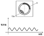
- FIG. 5 is a characteristic diagram of the drive motor current of the drum type washing machine in the first embodiment of the present invention.
- FIG. 6A is a characteristic diagram of a drive motor current of the drum type washing machine in the first embodiment of the present invention.
- FIG. 1 is a configuration diagram of a drum-type washing machine according to the first embodiment of the present invention.
- FIG. 2 is a schematic view of the ball balancer of the drum type washing machine according to the first embodiment of the present invention.
- FIG. 3 is a control block diagram of the drum type washing machine
- FIG. 6B is a characteristic diagram of a drive motor current of the drum type washing machine in the first embodiment of the present invention.
- FIG. 7 is a diagram showing a rotation speed sequence of the drum-type washing machine according to the third embodiment of the present invention.
- FIG. 8 is a diagram showing a rotation speed sequence of the drum type washing machine in the fourth embodiment of the present invention.
- FIG. 9 is a configuration diagram of a conventional drum-type washing machine.
- FIG. 1 is a configuration diagram of a drum-type washing machine according to the first embodiment of the present invention.
- FIG. 2 is a schematic diagram of the ball balancer according to the first embodiment of the present invention.
- a cylindrical water tank 2 with a bottom is accommodated inside the drum-type washing machine 1.
- a bottomed cylindrical drum 3 is accommodated in the water tank 2.
- the drum 3 is disposed such that a rotating shaft 31 that rotatably supports the drum 3 is inclined downward from the front side toward the back side.
- the water tank 2 is inclined and arranged along the drum 3 with the opening 2a as the front side.
- the rotating shaft 31 by tilting the rotating shaft 31, compared to when the rotating shaft 31 is set in the horizontal direction, water supplied into the water tank 2 is accumulated on the back side, and deep water can be stored even with a small amount of water. That is, the laundry 13 can be easily hydrated even with a small amount of water supply.
- the water tank 2 is supported by a spring 10 and a damper 5.
- the rotating shaft 31 may be horizontal.
- a triangular columnar baffle 16 that lifts and drops the laundry 13 as the drum 3 rotates.
- the drum 3 is driven to rotate, the laundry 13 lifted by the baffle 16 is struck against the water surface from the top of the drum 3 and is washed by tapping (mechanical force).
- the drum 3 is provided with a plurality of through holes 15. Water can be passed from the water tank 2 into the drum 3 through the through holes 15.
- a door 7 is provided in the opening 3a so as to be freely opened and closed.
- the opening 2a of the water tank 2 is provided with an annular sealing material (not shown) at its mouth edge.
- the front side of the sealing material is in contact with the back side of the door 7 and sealed, and even if the opening 2a of the water tank 2 that swings up and down, right and left and back and forth moves, the sealing material is deformed and pressed against the back side of the door 7 Sex is maintained.
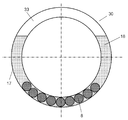
- a ball balancer (balancing part) 30 is provided in the opening 3 a on the front side of the drum 3.
- the ball balancer 30 includes an annular container 17 disposed on the front side of the drum 3, a rolling element 8 composed of a metal ball that can move in the annular container 17, and a viscous fluid 18 that is stored in the annular container 17. And a gas layer 33 (air).
- the ring-shaped annular container 17 is installed so as to be concentric with the drum 3. That is, the rotation axis of the annular container 17 coincides with the rotation axis of the rotation shaft 31.
- a viscous fluid 18 is stored inside the annular container 17.
- silicon oil is used as the viscous fluid 18.
- the viscous fluid 18 used in the present embodiment is not limited to silicon oil because the same effect can be obtained even with viscous liquids such as machine oil and other aqueous solutions.
- a driving motor 4 for rotating the drum 3 is attached to the inside of the drum type washing machine 1 below the water tank 2.
- the rotational drive of the drive motor 4 is transmitted to the drum pulley 24 connected to the rotary shaft 31 of the drum 3 via the belt 23.
- the drive motor 4 drives the drum 3 to rotate.
- the belt driving motor is described.
- a direct motor system that directly drives the drum 3 may be used.
- a water supply valve 11 is provided at the top of the drum type washing machine 1. Water from the water supply valve 11 flows into the detergent case 9 and is supplied into the water tank 2 while dissolving the detergent. In the rinsing process, since there is no detergent in the detergent case 9 even through the detergent case 9, rinsing water containing no detergent component is supplied.
- a drainage pump 19 is provided at the lower part of the drum-type washing machine 1 together with the drainage pipe 14. By driving the drainage pump 19, the washing water and the rinsing water in the water tank 2 are passed through the drainage pipe 14. Drained. In this embodiment, the drainage pump 19 drains the washing water and the rinsing water in the water tank 2, but a drainage valve may be provided instead of the drainage pump 19.
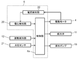
- FIG. 3 is a control block diagram of the drum type washing machine in the present embodiment.
- the control device 6 includes a control unit 6a, an eccentricity detection unit 20, and a current detection unit 22.
- the control unit 6 a instructs to drive the water supply valve 11, the drain pump 19, and the drive motor 4.
- the control unit 6a includes a system that can manage all input / output control including various sensor outputs such as the vibration detection unit 12 and the water level sensor 21 with a timer, and can know the time required for each operation and timing. .
- the control unit 6a is an electric circuit including a CPU, a memory, a driver circuit, and the like as a hardware configuration, and moves peripheral devices such as the drive motor 4 in accordance with a program stored in the memory in the control unit 6a.
- the current detection unit 22 detects the value and phase of the current applied to the drive motor 4 and outputs a signal to the eccentricity detection unit 20.
- the eccentricity detection unit 20 functions as an eccentric position detection unit that detects the eccentricity of the laundry and the eccentric position of the drum 3 caused by the rolling elements 8 based on the signal of the current detection unit. Furthermore, the eccentricity detection unit 20 also functions as an eccentricity detection unit that detects the amount of eccentricity of the drum 3 by comparing the magnitude of the current applied to the drive motor 4. That is, the control unit 6a can obtain the eccentric amount and the eccentric position of the drum 3 based on the current value and the phase detected by the eccentricity detection unit 20. The control unit 6a determines the eccentric position and the eccentric amount due to the laundry 13 and the position of the rolling element 8, and issues a command to the drive motor 4 to start up the rotation of the drum 3.
- the vibration detection unit 12 that detects the vibration of the water tank 2 is provided at the upper part on the back side of the water tank 2.
- the vibration detection unit 12 detects vibration of the water tank 2 in a series of steps of washing, rinsing, and dehydration. After the control unit 6a analyzes the vibration value in each step, the motor is optimally controlled by issuing a command to the drive motor 4.
- the vibration detection unit 12 includes at least one acceleration sensor, and detects vibration in at least one of the vertical direction, the horizontal direction, and the front-rear direction of the water tank 2.
- the acceleration sensor may be a semiconductor acceleration sensor, a piezoelectric acceleration sensor, or the like, and may be a uniaxial or biaxial acceleration sensor.
- FIG. 4 is a diagram showing a rotation speed sequence of the drum-type washing machine according to the present embodiment.
- 5, 6A and 6B are characteristic diagrams of the drive motor current in the present embodiment.
- the dehydration operation does not mean only final dehydration in the dehydration process, but also includes intermediate dehydration performed after the washing process or after the first rinsing process.
- a drive voltage is applied to the drive motor 4 according to a command from the control unit 6a.
- the drive motor 4 is operated from low speed rotation to high speed rotation, and the rotation speed of the drum 3 is gradually increased.
- the drive motor 4 is a permanent magnet synchronous motor, the rotor position of the drive motor 4 is detected. Thereby, it is possible to increase the rotational speed safely and at high speed by preventing the drive motor 4 from stepping out.
- the controller 6a increases and maintains the rotational speed of the drum 3 to a rotational speed at which the gravity applied to the laundry 13 and the rolling element 8 is smaller than the centrifugal force due to the rotation of the drum 3 ((1) in FIG. 4).
- the laundry 13 sticks to the inner wall of the drum 3.
- the rotational speed of the drum 3 at this time is slightly moved along the rotational direction of the drum 3 in such a manner that the rolling element 8 in the annular container 17 is dragged by the viscous fluid 18 in the annular container 17. 3, and a rotation speed that remains at a fixed position in the annular container 17 without rotating together.
- the following conditions are required at the drum rotation speed to which the laundry 13 is stuck. That is, the self-weight determined by the density, diameter, and number of the rolling elements 8, the viscous resistance force when the viscous fluid 18 passes through the gap between the rolling elements 8 and the inner surface of the annular container 17, and the rolling elements 8 and the annular container 17 The frictional force is balanced. Further, since the influence of centrifugal force increases as the rotational speed of the drum 3 increases, the rolling element 8 rotates together with the drum 3. When the rolling element 8 rotates together with the drum 3, the eccentricity 13 a caused by the rolling element 8 and the laundry 13 becomes a fluctuation factor of the current of the drive motor 4.
- the laundry 13 is rotating, and therefore the laundry is detected from the current value applied to the drive motor 4 detected by the current detection unit 22 or the amount of fluctuation of the current value. 13 eccentric amounts can be determined. Further, the unbalance position of the laundry 13 can be determined from the torque fluctuation (phase).
- the laundry 13 sticks to the inner wall to generate an eccentric 13 a (unbalance), and the drum 3 rotates once ( It is possible to detect the eccentric position and the eccentric amount due to the deviation of the laundry 13 within one cycle.
- the rotation speed is set to 80 rpm at which the bias of the laundry 13 can be easily confirmed.
- the controller 6 a determines the eccentric position of the drum 3 at this time, that is, the eccentric position and the eccentric amount of the laundry 13.
- the vibration detection unit 12 is a triaxial acceleration sensor.
- the up / down direction, left / right direction, and front / rear direction of the water tank 2 are detected, and the unbalance position is detected by the phase difference of each axis according to the unbalance position.
- the unbalanced position is on the front side of the drum 3, the phase difference between the left and right direction and the front and rear direction of the water tank 2 is increased.
- the control unit 6a can determine the unbalance position based on the signal detected by the vibration detection unit 12. It becomes.
- the eccentricity detection unit 20 monitors the current value (torque current) and phase applied to the drive motor 4.
- the eccentric position is obtained from the period of the fluctuating current.
- FIG. 6A shows the characteristics of the drive motor current when the water tank imbalance is large
- FIG. 6B shows the characteristics of the drive motor current when the water tank imbalance is small.
- the amount of eccentricity can be determined by the magnitude of the current value and the current fluctuation value.
- the drum 3 is raised to 80 rpm and maintained so that the rolling element 8 is stopped without rotating at the lower part in the annular container 17 ((1) in FIG. 4). ). Then, the position and amount of the eccentric 13a of the laundry 13 are determined.
- the control unit 6a accelerates the rotation of the drum 3 from the state where the rolling element 8 remains at the lower part of the water tank 2 (point A in FIG. 4). As the rotational speed of the drum 3 increases, the centrifugal force increases and the rolling element 8 starts to rotate together with the drum 3 ((2) in FIG. 4).
- the controller 6a detects the amount of eccentricity of the entire water tank 2 during acceleration.
- the controller 6a determines that the value of the eccentricity is greater than the predetermined threshold value X
- the controller 6a controls the rotation acceleration of the drum 3 so as to be smaller than the threshold value X (point B in FIG. 4). Then, the rotational speed of the drum 3 passes through the resonant rotational speed in a state where the rotational speed is smaller than the predetermined threshold value X, and is accelerated to a rotational speed higher than the resonant rotational range.
- the unbalance amount decreases due to the spread between the plurality of rolling elements 8, or the moisture in the laundry 13 decreasing with the rotation of the drum 3 due to centrifugal force.
- the rolling element 8 may not be controlled to be in a position facing the unbalanced position of the laundry 13 only by information at the time of acceleration.
- control unit 6a detects the amount of eccentricity of the entire water tank 2 during acceleration.
- the amount of eccentricity increases as the deviation from the position at which the rolling element 8 and the laundry 13 are unbalanced increases, and the aquarium 2 vibrates greatly.
- the control unit 6a controls the acceleration of the drum rotation so that the value of the eccentricity becomes smaller than a predetermined threshold, passes through the resonance rotation speed in a state of being smaller than the predetermined threshold, and has a rotation speed higher than the resonance rotation region. Accelerate all at once. As a result, the vibration of the drum can always be minimized.
- the control unit 6a of the drum type washing machine in the second embodiment of the present invention performs the following control. That is, when the controller 6a rotates the eccentric amount and eccentric position of the drum 3 before acceleration, the unbalance of the drum 3 during acceleration, and the rolling element 8 based on the signal obtained by the eccentricity detecting unit 20. The position of each rolling element during drum acceleration, that is, the rolling element 8 is determined from the amount of eccentricity. Then, the drive motor is controlled so that the rolling elements 8 and the unbalance of the laundry are in opposite positions.
- Other configurations use the first embodiment of the present invention. Hereinafter, different points will be described.
- the rolling element 8 stays at the lower part of the drum 3, thereby washing the drum 3.
- the unbalance amount and unbalance position of the object 13 can be determined.
- the weight of the rolling element 8 in the annular container 17 is also known.
- the unbalance during acceleration sticks to the drum 3 more than before acceleration due to an increase in centrifugal force, it does not move in the circumferential direction of the drum 3. Therefore, the position of the eccentric 13a during acceleration can always be grasped.
- the position of the rolling element 8 is based on the speed of the drum 3, it can always be grasped.
- the decrease in the unbalance amount during acceleration of the drum 3 can be estimated from the vibration displacement of the drum 3 by the eccentricity detection unit 20 and the decrease in the current value of the drive motor 4 detected by the current detection unit 22.
- the total unbalance amount between the eccentric 13 a of the laundry 13 and the rolling element 8 can be determined from the vibration displacement of the drum 3.
- the eccentric position and eccentric amount of the drum 3 during acceleration can be determined from the amount and position of the eccentric 13a before acceleration and the speed and acceleration of the drum 3.
- the rotation of the drum 3 can be controlled so that the rolling element 8 and the unbalance are opposed to each other. Details of how to increase the rotational speed of the drum will be described below with reference to FIG.
- control unit 6a accelerates the drum 3 from the state where the rolling element 8 stays in the lower part of the water tank 2 (point A in FIG. 4).
- the rotational speed of the drum 3 increases, the centrifugal force increases and the rolling element 8 starts to rotate together with the drum 3.
- the dynamic balance of the drum 3 may not be achieved due to the influence of both the rolling elements 8 and the laundry 13 ((2) in FIG. 4).
- the controller 6a Since the control unit 6a detects the unbalance position at a constant speed of 80 rpm, the controller 6a grasps the position of the eccentric 13a of the laundry 13 at the time of starting acceleration. Therefore, the position of the eccentric 13a of the laundry 13 at an arbitrary time during acceleration can be estimated from the drum rotation speed. Moreover, the position of the rolling element 8 at the time of starting acceleration can be estimated by storing the position of the rolling element 8 according to the rotational speed in advance. Therefore, the control part 6a can grasp
- the control unit 6a faces the eccentricity 13a of the rolling element 8 and the laundry 13 so
- the drive motor 4 is controlled so as to be in a position to perform (B in FIG. 4).
- This operation corrects the positional relationship between the rolling elements 8 and the eccentric 13a of the laundry 13 by increasing or decreasing the acceleration of the drive motor 4 of the drum 3 for a short time, for example.
- the acceleration of the driving motor 4 of the drum 3 is temporarily increased to oppose it. To be in the position.
- the laundry 13 can be moved relative to the rolling elements 8 by changing the acceleration of the drive motor 4 of the drum 3. Then, the positional relationship between the rolling element 8 and the eccentricity 13a of the laundry 13 is corrected so as to be brought to the opposite position when the drum 3 passes the resonance rotation speed, and the rotation speed is accelerated to a higher rotation speed than the resonance rotation area. In this way, the vibration is suppressed by bringing it to the opposite position at the drum resonance rotation speed at which the vibration due to unbalance increases ((3) in FIG. 4).
- the acceleration of the drum 3 is changed when the amount of eccentricity is larger than the threshold value X.
- the drum 3 is rotated up to the resonance rotational speed so that the eccentric amount does not become the threshold value X by grasping and estimating the position of the eccentricity 13a of the rolling element 8 and the laundry 13. Can speed up. Therefore, the rotational speed of the drum 3 can be raised smoothly without causing large vibrations even before reaching the resonant rotational speed.
- the unbalance amount is reduced due to the spread between the plurality of rolling elements 8, or the moisture in the laundry 13 is reduced with the rotation of the drum 3 due to the centrifugal force.
- the rolling element 8 and the laundry 13 cannot be controlled to face each other only by information at the time of acceleration.
- the control unit 6a detects the eccentric amount of the entire water tank 2 during acceleration. As the displacement from the position where the rolling element 8 and the eccentric 13a of the laundry 13 are opposed to each other increases, the amount of eccentricity increases and the water tank 2 vibrates greatly. Therefore, the control unit 6a controls the acceleration of the rotation of the drum 3 so that the value of the eccentricity becomes smaller than a predetermined threshold value. In a state in which the current value detected by the current detection unit 22 or the fluctuation amount of the current value is smaller than a predetermined threshold value, the acceleration is accelerated to a rotational speed higher than the resonance rotational region. Thereby, a big vibration does not generate
- the drum 3 since the position of the rolling element 8 during acceleration of the drum 3 can be determined by analysis, the drum 3 can be controlled quickly and accurately at a position where the rolling element 8 and the eccentric 13a of the laundry 13 face each other. can do. For this reason, the vibration of the drum 3 which becomes large before and after passing through the resonance rotation can be minimized over a wide range.
- FIG. 7 is a diagram showing a rotation speed sequence of the drum-type washing machine according to the third embodiment of the present invention.
- a drive voltage is applied to the drive motor 4 according to a command from the control unit 6a.
- the drive motor 4 is operated from low speed rotation to high speed rotation, and the rotation speed of the drum 3 is gradually increased.
- the drive motor 4 is a permanent magnet synchronous motor, the rotor position of the drive motor 4 is detected. Thereby, it is possible to increase the rotational speed safely and at high speed by preventing the drive motor 4 from stepping out.
- the controller 6a increases and maintains the rotational speed of the drum 3 to a rotational speed at which the gravity applied to the laundry 13 and the rolling element 8 is smaller than the centrifugal force generated by the rotation of the drum 3 ((1) in FIG. 7).
- the control unit 6a makes the rolling element 8 stay in the lower part of the annular container 17, and determines the position and amount of the eccentric 13a of the laundry 13. And when the eccentric 13a of the laundry 13 is located in the position facing the rolling element 8, the drum is accelerated at a stretch to a rotational speed higher than the resonant rotational speed (point A in FIG. 7). As the rolling element 8 rotates, the rolling element 8 moves slightly to the rotational direction side, so that when the unbalanced position of the laundry 13 is located above the drum 3 and on the rotational direction side, the control unit 6a The drum 3 is accelerated ((2) in FIG. 7).
- the vibration at can be suppressed.
- the unbalance amount of the clothing is determined at 80 rpm and the unbalance amount of the clothing is smaller than the unbalance correction amount of the rolling elements, the plurality of rolling elements 8 are brought into contact with each other from the contacted state to the entire annular container 17.
- the rotation of the drum 3 is controlled so as to be in a scattered state.
- the unbalance amount during rotation of the rolling element 8 itself is lowered, and the drum 3 is accelerated at a stretch to a rotational speed higher than the resonance rotational speed.
- This control can suppress drum vibration around the resonance rotational speed even when the amount of eccentricity of the garment is small.
- FIG. 8 is a diagram showing a rotation speed sequence of the drum type washing machine according to the fourth embodiment of the present invention.
- the timing for accelerating the drum 3 is different from that of the third embodiment.
- control unit 6a rotates the drum 3 at a rotational speed at which the laundry in the drum 3 does not fall and the rolling element 8 stays below the drum 3 ((1 in FIG. 8). )),
- the eccentric position of the laundry detected by the eccentricity detection unit 20 is analyzed, and the drum 3 is accelerated when the position of the eccentric 13a of the laundry 13 is above the rotary shaft 31.
- the other configuration uses the third embodiment. Hereinafter, different points will be described.
- the rotation speed of the drum 3 is maintained at 80 rpm ((1) in FIG. 8). At this time, the rolling element 8 remains at the lower part of the drum 3. If the drum 3 is accelerated when the eccentric 13a of the laundry 13 is positioned at the upper part of the drum 3, the rolling element 8 stays at the lower part of the drum 3, so the eccentric 13a of the laundry 13 and the rolling element 8 are It can be in an opposing state. Therefore, the control unit 6a detects the position of the eccentricity 13a of the laundry 13 by the eccentricity detection unit 20, and accelerates the drum 3 when the eccentricity 13a of the laundry 13 is above the drum 3.
- the drum-type washing machine of the invention is a bottomed cylindrical drum that is rotatably supported by a horizontal or inclined rotating shaft, a water tank that houses the drum, a drive motor that drives the drum, An annular container provided integrally with the drum, and a plurality of rolling elements movably accommodated inside the annular container.
- an eccentricity detection unit that detects the eccentricity of the laundry in the drum and the eccentric state of the drum caused by the rolling elements
- a control unit that analyzes the eccentric position detected by the eccentricity detection unit and controls the drive motor With. Then, the control unit detects the eccentric state of the drum by the eccentricity detection unit in a state where the laundry in the drum does not fall and the drum is rotated at a rotation speed at which the rolling elements stay below the drum.
- the eccentric position of the drum is detected, and the control unit detects the eccentric state of the drum by the eccentricity detection unit and then accelerates the drum, and the drum rotates when the drum rotation speed passes the resonance rotation speed.
- the drive motor is controlled so that the eccentric position of is opposite to the rolling element.
- the present invention detects the amount of eccentricity of the drum, and when the control unit detects that the amount of eccentricity of the drum is larger than a predetermined threshold during the acceleration operation of the drum, the amount of eccentricity of the drum is less than the predetermined threshold.
- the drive motor is controlled to be small.
- the present invention determines the drum acceleration up to the resonance rotational speed based on the eccentric position of the drum before the drum acceleration and the position of the rolling element, and when the drum rotation speed passes the resonance rotation speed,
- the drive motor is controlled so that the rolling elements and the unbalance of the laundry are in opposite positions.
- the controller detects the eccentricity in a state in which the laundry in the drum does not fall and the drum is rotated at a rotational speed at which the rolling element stays below the drum.
- the eccentric position of the laundry detected by is analyzed.
- the drum is accelerated, and the drive motor is controlled so that the drum and the rolling element rotate integrally at a rotational speed lower than the resonance rotational speed with the eccentric position of the rolling element and the laundry facing each other.
- This configuration allows the drum to rotate, but the rolling element stays at the bottom of the drum and does not rotate together.
- the vibration of the drum is caused by the imbalance of the clothes rotating together with the drum, and the unbalance amount of only the clothes can be detected from the vibration fluctuation of the drum.
- the torque of the motor varies during rotation.
- the analysis unit analyzes the unbalance position from the fluctuation period. Then, when the unbalance is located at the upper part of the drum, the position where the torque fluctuation of the motor shows the maximum coincides, and at this time, the unbalance and the rolling element are in a relative positional relationship of opposite phases. Therefore, if the motor is accelerated when the imbalance reaches the maximum point, the vibration of the drum can be suppressed when the resonance rotational speed is passed.
- the controller detects the eccentricity in a state in which the laundry in the drum does not fall and the drum is rotated at a rotational speed at which the rolling element stays below the drum.
- the eccentric position of the laundry detected by the above is analyzed, and the drum is accelerated when the eccentric position of the laundry is above the rotation axis.
- This configuration allows the drum to rotate, but the rolling element stays at the bottom of the drum and does not rotate together.
- the swing of the drum is caused by the imbalance of the clothes rotating together with the drum, and the unbalance amount of only the clothes can be detected from the vibration fluctuation of the drum.
- the unvarying rotation causes the motor to undergo torque fluctuations during rotation.
- the analysis unit analyzes the unbalanced position from the fluctuation period. Since the position where the torque fluctuation of the motor shows the maximum coincides with the time when the uncrowd is located at the upper part of the drum, at this time, the unbalance and the rolling element are in a relative positional relationship of opposite phases. Therefore, if the drum is accelerated when the unbalance reaches the maximum point, that is, when the unbalance is located above the drum, vibration of the drum can be suppressed when the resonance rotational speed is passed.
- control unit analyzes the eccentric position of the drum detected by the eccentricity detection unit, and controls to accelerate the drum at a position where the eccentric position of the drum and the rolling element face each other and pass the resonance point. I do.
- This configuration reduces drum imbalance with simple detection and control, and allows the drum rotation speed to reach the resonance rotation speed.
- the present invention further includes a vibration detection unit that detects the vibration of the drum.
- This configuration can detect the vibration displacement of the drum even when the unbalanced position cannot be analyzed due to the fact that a plurality of rolling elements are dispersed while the drum is rotating or the unbalanced state of the clothing changes. Therefore, the drum rotation is accelerated and decelerated until the resonance rotational speed is reached, so that the vibration displacement of the drum can be further controlled, and the drum vibration can be minimized when the resonance rotational speed is passed.
- the drum type washing machine according to the present invention can increase the rotation speed of the drum so that the rolling element can obtain a vibration suppressing effect against the unbalance, and therefore can further reduce the unbalance. Therefore, since vibration at the time of activation can be suppressed, it is useful as a drum-type washing machine or a cleaning device for home use or business use.
Abstract
A drum type washing machine is provided with a closed-end cylindrical drum (3) which is supported in a rotatable manner by a horizontal or tilted rotating shaft (31), a water tank (2) which receives the drum (3), a drive motor (4) which drives the drum (3), an annular container (17) which is provided integrally with the drum (3), and rolling bodies (8) which are received in a movable manner within the annular container (17). The drum type washing machine is further provided with: an imbalance detection unit which, while the drum (3) is rotated, detects the state of imbalance of the drum (3) created by the imbalance of laundry within the drum (3) and by the rolling bodies (8); and a control unit which analyzes the position of imbalance detected by the imbalance detection unit and which controls the drive motor (4). The control unit detects the state of imbalance of the drum (3) by means of the imbalance detection unit while rotating the drum (3) at a rotational speed at which the laundry within the drum (3) does not fall and at which the rolling bodies (8) stay at the lower part of the drum (3).
Description
本発明は、弾性的に支持された水槽内に洗濯物を収容して回転可能なドラムを備え、そのドラム内で洗濯物の洗い、すすぎ、脱水を行うドラム式の洗濯機に関する。
The present invention relates to a drum-type washing machine having a drum that can be rotated by accommodating laundry in an elastically supported water tub, and washing, rinsing, and dewatering the laundry in the drum.
一般的に、水平または傾斜した回転軸を有するドラム式洗濯機の脱水工程においては、しばしば洗濯物がドラム内で不均一な状態、すなわちアンバランスな状態になる。その結果、脱水中に回転軸には偏った力が加わり、振動が発生する。振動の振幅は回転ドラムの回転速度の2乗に比例して増大する。その振動のために洗濯機自身が移動したり、また、騒音が激しいために、ある回転速度以上では運転することができなくなったりしてしまうなどの問題が発生する。
Generally, in a dewatering process of a drum type washing machine having a horizontal or inclined rotating shaft, the laundry is often in an uneven state, that is, an unbalanced state in the drum. As a result, a biased force is applied to the rotating shaft during dehydration, and vibration is generated. The amplitude of vibration increases in proportion to the square of the rotational speed of the rotating drum. Problems such as the washing machine itself moving due to the vibration, and the noise being so intense that it becomes impossible to drive at a certain rotational speed or higher.
洗濯物のアンバランスによる振動を低減するために、金属球(以降、転動体と呼ぶ)を使用したボールバランサシステムがある。ボールバランサは、ドラムの内周に取り付けた環状容器部内に、回転方向(周方向)に自由度をもつ複数のボールを備えている。ボールバランサは、偏心荷重を生じさせるアンバランス体に対して自動的にボールが対向位置に移動するという力学現象を利用したバランス装置である。
There is a ball balancer system that uses metal balls (hereinafter referred to as rolling elements) to reduce vibration due to unbalanced laundry. The ball balancer includes a plurality of balls having degrees of freedom in the rotation direction (circumferential direction) in an annular container portion attached to the inner periphery of the drum. The ball balancer is a balance device that utilizes a dynamic phenomenon in which a ball automatically moves to an opposing position with respect to an unbalanced body that generates an eccentric load.
また、ドラムの開口部側にのみボールバランサを配置したシングルボールバランサの他に、ドラムの開口部側及び底面側の2箇所に、ボールバランサを配置したダブルボールバランサも知られている(例えば、特許文献1参照)。
In addition to a single ball balancer in which a ball balancer is disposed only on the opening side of the drum, a double ball balancer in which ball balancers are disposed at two locations on the opening side and bottom side of the drum is also known (for example, Patent Document 1).
図9は、従来のドラム式洗濯機を示す図である。ドラム101の開口部側および底面側に、環状容器102が設けられており、それぞれの環状容器102には金属球からなる転動体103が移動可能に内包され、ボールバランサ104を構成している。これらボールバランサ104はシングルボールバランサと原理的には同じである。すなわち、どちらのボールバランサ104も、脱水工程において経時的に変化する洗濯物のアンバランス量に刻一刻と対応して、複数の転動体103が位置を変え、自動的にアンバランスを修正する。
FIG. 9 is a view showing a conventional drum-type washing machine. An annular container 102 is provided on the opening side and the bottom surface side of the drum 101, and a rolling element 103 made of a metal sphere is movably included in each annular container 102 to constitute a ball balancer 104. These ball balancers 104 are in principle the same as single ball balancers. That is, in both ball balancers 104, the plurality of rolling elements 103 change their positions and automatically correct the unbalance in response to the unbalance amount of the laundry that changes over time in the dehydration process.
従来のドラム式洗濯機では、ドラム101を共振回転速度以下の回転速度で回転させ、所定の時間、転動体103が偏心荷重に対して同相位置に移動して、その同相位置の状態を維持する。その後、ドラム101の回転速度をゆるやかに加速して、共振回転速度を通過する。これにより、転動体103が自動バランシングの原理により自動的にアンバランスの対向位置に移動することで振動を抑制している。
In the conventional drum type washing machine, the drum 101 is rotated at a rotation speed equal to or lower than the resonance rotation speed, and the rolling element 103 moves to the in-phase position with respect to the eccentric load for a predetermined time, and maintains the in-phase position state. . Thereafter, the rotational speed of the drum 101 is gently accelerated to pass through the resonant rotational speed. Thereby, the rolling element 103 is automatically moved to the unbalanced opposing position by the principle of automatic balancing, thereby suppressing vibration.
また、従来の他のドラム式洗濯機では、ドラム101の回転を共振回転速度の高速側近傍である過渡振動回転速度領域の上限まで上昇させた後、アンバランスを打ち消す方向に転動体を移動させるために、ドラム101の回転速度を不連続な回転速度に微小変化させてドラム101を制御している(例えば、特許文献2参照)。
In another conventional drum-type washing machine, after the rotation of the drum 101 is increased to the upper limit of the transient vibration rotation speed region that is near the high speed side of the resonance rotation speed, the rolling element is moved in a direction that cancels the unbalance. Therefore, the drum 101 is controlled by minutely changing the rotation speed of the drum 101 to a discontinuous rotation speed (see, for example, Patent Document 2).
しかしながら、従来の構成では、ドラム101の回転速度が共振回転速度よりも低い状態において、転動体103は洗濯物のアンバランスと同相位置に存在する。このため、転動体103は洗濯物と伴にアンバランスとして働くため、共振回転速度を通過するときには振動が大きくなることがあるという課題を有していた。
However, in the conventional configuration, the rolling element 103 is in the same phase as the laundry unbalance in a state where the rotation speed of the drum 101 is lower than the resonance rotation speed. For this reason, since the rolling element 103 works as an imbalance with the laundry, there is a problem that vibration may increase when passing through the resonance rotational speed.
また、ドラム101内の洗濯物の偏心量や偏心位置を検知する時に、転動体103もドラム101と同時に回転するために、精度よく洗濯物の偏心状態を検知することは困難である。さらに、洗濯物の偏心量が少ないなど、偏心状態によっては、アンバランスを打ち消すための転動体103が、逆にアンバランスの原因となるという課題を有していた。
Also, when detecting the amount of eccentricity and the eccentric position of the laundry in the drum 101, it is difficult to accurately detect the eccentric state of the laundry because the rolling element 103 also rotates simultaneously with the drum 101. Furthermore, depending on the eccentric state, for example, the amount of eccentricity of the laundry is small, the rolling element 103 for canceling the unbalance has a problem that it causes the unbalance.
本発明のドラム式洗濯機は、水平または傾斜した回転軸にて回転可能に支持された有底円筒状のドラムと、ドラムを収容する水槽と、ドラムを駆動する駆動モータと、ドラムと一体に設けられた環状容器と、環状容器の内部に移動自在に収容された複数の転動体を有する。さらに、ドラムの回転時に、ドラム内の洗濯物の偏りや転動体によって生じるドラムの偏心状態を検知する偏心検知部と、偏心検知部により検知した偏心位置を解析するとともに駆動モータを制御する制御部とを備える。そして、制御部は、ドラム内の洗濯物が落下せず、かつ、転動体がドラム下部に留まる回転速度にてドラムを回転させた状態で、偏心検知部によりドラムの偏心状態を検知する。
The drum-type washing machine of the present invention is integrally formed with a bottomed cylindrical drum rotatably supported by a horizontal or inclined rotating shaft, a water tank that accommodates the drum, a drive motor that drives the drum, and the drum. An annular container provided and a plurality of rolling elements movably accommodated inside the annular container. Further, when the drum rotates, an eccentricity detection unit that detects the eccentricity of the laundry in the drum and the eccentric state of the drum caused by the rolling elements, and a control unit that analyzes the eccentric position detected by the eccentricity detection unit and controls the drive motor With. Then, the control unit detects the eccentric state of the drum by the eccentricity detection unit in a state where the laundry in the drum does not fall and the drum is rotated at a rotation speed at which the rolling element stays at the lower part of the drum.
これにより、ドラム内の洗濯物のアンバランスを転動体の影響を受けずに精度よく検知することができる。加えて、本発明のドラム式洗濯機は、洗濯物のアンバランスに対して転動体が振動抑制効果を得られるようにドラムの回転を立ち上げることができるため、共振回転速度におけるドラムの振動を最小限に抑制することができる。
This makes it possible to accurately detect the unbalance of the laundry in the drum without being affected by the rolling elements. In addition, the drum-type washing machine of the present invention can start up the rotation of the drum so that the rolling elements can obtain a vibration suppressing effect against the unbalance of the laundry, so that the vibration of the drum at the resonance rotational speed can be increased. It can be minimized.
また、本発明のドラム式洗濯機は、制御部が、洗濯物の偏心位置を解析した後にドラムを加速させて、共振回転速度よりも低い回転速度で、転動体と洗濯物の偏心位置が対向する状態でドラムと転動体が一体で回転するように駆動モータを制御する。
Further, in the drum type washing machine of the present invention, the controller accelerates the drum after analyzing the eccentric position of the laundry, and the eccentric position of the rolling element and the laundry is opposed at a rotational speed lower than the resonant rotational speed. In this state, the drive motor is controlled so that the drum and the rolling element rotate together.
これにより、洗濯物のアンバランスに対して転動体が振動抑制効果を得られるようにドラムの回転を立ち上げることで、低振動のまま共振回転速度まで立ち上げることができるため、共振回転速度通過時にドラムの振動を抑えることができる。
As a result, it is possible to start up to the resonance rotation speed with low vibration by raising the rotation of the drum so that the rolling element can obtain a vibration suppressing effect against the unbalance of the laundry, so that the resonance rotation speed passes. Sometimes drum vibration can be suppressed.
また、本発明のドラム式洗濯機は、制御部が、洗濯物の偏心位置を解析し、洗濯物の偏心位置が回転軸より上部にあるときにドラムを加速させる。
In the drum type washing machine of the present invention, the control unit analyzes the eccentric position of the laundry, and accelerates the drum when the eccentric position of the laundry is above the rotation axis.
これにより、アンバランスに対して転動体が振動抑制効果を得られるようにドラムの回転を立ち上げることで、低振動のまま共振回転速度まで立ち上げることができるため、共振回転速度通過時にドラムの振動を抑えることができる。
As a result, it is possible to raise the resonance rotational speed with low vibration by raising the rotation of the drum so that the rolling element can obtain a vibration suppressing effect against unbalance. Vibration can be suppressed.
以下、本発明の実施の形態について、図面を参照しながら説明する。なお、この実施の形態によって本発明が限定されるものではない。
Hereinafter, embodiments of the present invention will be described with reference to the drawings. Note that the present invention is not limited to the embodiments.
(第1の実施の形態)
図1は本発明の第1の実施の形態におけるドラム式洗濯機の構成図である。図2は、本発明の第1の実施の形態におけるボールバランサの概略図である。 (First embodiment)
FIG. 1 is a configuration diagram of a drum-type washing machine according to the first embodiment of the present invention. FIG. 2 is a schematic diagram of the ball balancer according to the first embodiment of the present invention.
ドラム式洗濯機1の内側には、有底円筒状の水槽2が収容されている。水槽2の内部には有底円筒状のドラム3が収容されている。ドラム式洗濯機1の正面側には、水槽2の開口部2aを通してドラム3内に通じる開口部3aが形成されている。ドラム3は、ドラム3を回転支持する回転軸31が正面側から背面側に向けて下向きに傾斜して配置されている。水槽2は開口部2aを正面側とし、ドラム3に沿うように傾斜配置されている。回転軸31を傾斜させることで、水槽2の前面側の開口を上側に配置することができ、大きく屈む姿勢をとることなくドラム3内の洗濯物13が取り出せる。また、回転軸31を傾斜させることで、回転軸31を水平方向とした場合に比べ、水槽2内に給水された水が背面側に溜まって、少ない水量でも深い貯水となる。すなわち、少ない給水量でも洗濯物13が含水しやすくすくなる。水槽2はバネ10とダンパ5によって支持されている。なお、洗濯物13の取り出しやすさや給水量を考慮しなければ、回転軸31は水平であってもよい。
Inside the drum-type washing machine 1, a cylindrical water tank 2 with a bottom is accommodated. A bottomed cylindrical drum 3 is accommodated in the water tank 2. On the front side of the drum-type washing machine 1, an opening 3 a that communicates with the drum 3 through the opening 2 a of the water tub 2 is formed. The drum 3 is disposed such that a rotating shaft 31 that rotatably supports the drum 3 is inclined downward from the front side toward the back side. The water tank 2 is inclined and arranged along the drum 3 with the opening 2a as the front side. By inclining the rotation shaft 31, the opening on the front side of the water tub 2 can be arranged on the upper side, and the laundry 13 in the drum 3 can be taken out without taking a posture of bending greatly. In addition, by tilting the rotating shaft 31, compared to when the rotating shaft 31 is set in the horizontal direction, water supplied into the water tank 2 is accumulated on the back side, and deep water can be stored even with a small amount of water. That is, the laundry 13 can be easily hydrated even with a small amount of water supply. The water tank 2 is supported by a spring 10 and a damper 5. In addition, if the ease of taking out the laundry 13 and the amount of water supply are not considered, the rotating shaft 31 may be horizontal.
ドラム3の内部には、ドラム3が回転することによって洗濯物13を持ち上げて落とす三角柱状のバッフル16が設けられている。ドラム3が回転駆動することにより、バッフル16によって持ち上げられた洗濯物13は、ドラム3の上部から水面に叩きつけられ、叩き洗い(機械力)によって洗浄がなされる。さらに、ドラム3には複数の透孔15が設けられている。透孔15を介して水槽2からドラム3内に通水および通気ができる。
Inside the drum 3, there is provided a triangular columnar baffle 16 that lifts and drops the laundry 13 as the drum 3 rotates. When the drum 3 is driven to rotate, the laundry 13 lifted by the baffle 16 is struck against the water surface from the top of the drum 3 and is washed by tapping (mechanical force). Further, the drum 3 is provided with a plurality of through holes 15. Water can be passed from the water tank 2 into the drum 3 through the through holes 15.
また、開口部3aには扉7が開閉自在に設けられている。水槽2の開口部2aは、その口縁に環状のシール材(図示せず)が装着されている。シール材の前面側は扉7の背面側に当接して密閉し、上下左右、前後に揺動する水槽2の開口2aが動いても、シール材が変形し扉7背面側へ押圧するので密閉性が維持されている。
Further, a door 7 is provided in the opening 3a so as to be freely opened and closed. The opening 2a of the water tank 2 is provided with an annular sealing material (not shown) at its mouth edge. The front side of the sealing material is in contact with the back side of the door 7 and sealed, and even if the opening 2a of the water tank 2 that swings up and down, right and left and back and forth moves, the sealing material is deformed and pressed against the back side of the door 7 Sex is maintained.
ドラム3の前面側の開口部3aには、ボールバランサ(バランシング部)30が設けられている。ボールバランサ30は、ドラム3の正面側に配置された環状容器17と、環状容器17内を移動可能な金属球で構成される転動体8と、環状容器17内に貯留される粘性流体18と気体層33(空気)とを有している。リング状となる環状容器17はドラム3と同心となるように設置されている。すなわち、環状容器17の回転軸心は、回転軸31の回転軸心と一致している。転動体8の動きを制御するために、環状容器17の内部には粘性流体18が貯留されている。本実施の形態では粘性流体18としてシリコンオイルを用いている。なお、マシン油その他水溶液などの粘性のある液体であっても同様の効果が得られることから、本実施の形態で用いる粘性流体18をシリコンオイルに限定するものではない。
A ball balancer (balancing part) 30 is provided in the opening 3 a on the front side of the drum 3. The ball balancer 30 includes an annular container 17 disposed on the front side of the drum 3, a rolling element 8 composed of a metal ball that can move in the annular container 17, and a viscous fluid 18 that is stored in the annular container 17. And a gas layer 33 (air). The ring-shaped annular container 17 is installed so as to be concentric with the drum 3. That is, the rotation axis of the annular container 17 coincides with the rotation axis of the rotation shaft 31. In order to control the movement of the rolling element 8, a viscous fluid 18 is stored inside the annular container 17. In the present embodiment, silicon oil is used as the viscous fluid 18. Note that the viscous fluid 18 used in the present embodiment is not limited to silicon oil because the same effect can be obtained even with viscous liquids such as machine oil and other aqueous solutions.
ドラム式洗濯機1の内部で水槽2の下方には、ドラム3を回転駆動するための駆動モータ4が取り付けられている。駆動モータ4の回転駆動が、ベルト23を介してドラム3の回転軸31に連結されたドラムプーリ24に伝達される。これにより、駆動モータ4がドラム3を回転駆動する。なお、本実施の形態ではベルト駆動のモータで説明しているが、ドラム3を直接駆動するダイレクトモータ方式としてもよい。
A driving motor 4 for rotating the drum 3 is attached to the inside of the drum type washing machine 1 below the water tank 2. The rotational drive of the drive motor 4 is transmitted to the drum pulley 24 connected to the rotary shaft 31 of the drum 3 via the belt 23. As a result, the drive motor 4 drives the drum 3 to rotate. In this embodiment, the belt driving motor is described. However, a direct motor system that directly drives the drum 3 may be used.
ドラム式洗濯機1の上部には、給水弁11が設けられている。給水弁11からの水は洗剤ケース9に流れ込み、洗剤を溶かしながら水槽2内に供給される。すすぎ工程においては、洗剤ケース9を介しても洗剤ケース9内には洗剤がないので、洗剤成分を含まないすすぎ水が給水される。また、ドラム式洗濯機1の下部には、排水管14とともに排水ポンプ19が設けられており、排水ポンプ19を駆動させることで、水槽2内の洗浄水やすすぎ水が排水管14を介して排水される。なお、本実施の形態では排水ポンプ19によって、水槽2内の洗浄水やすすぎ水を排水することとしたが、排水ポンプ19に代えて排水弁を設けてもよい。
At the top of the drum type washing machine 1, a water supply valve 11 is provided. Water from the water supply valve 11 flows into the detergent case 9 and is supplied into the water tank 2 while dissolving the detergent. In the rinsing process, since there is no detergent in the detergent case 9 even through the detergent case 9, rinsing water containing no detergent component is supplied. A drainage pump 19 is provided at the lower part of the drum-type washing machine 1 together with the drainage pipe 14. By driving the drainage pump 19, the washing water and the rinsing water in the water tank 2 are passed through the drainage pipe 14. Drained. In this embodiment, the drainage pump 19 drains the washing water and the rinsing water in the water tank 2, but a drainage valve may be provided instead of the drainage pump 19.
次に、駆動モータ4等を制御し、洗い、すすぎ、脱水等の工程を制御する制御装置6の詳細を図3により説明する。図3は本実施の形態におけるドラム式洗濯機の制御ブロック図である。制御装置6は、制御部6aと、偏心検知部20と、電流検知部22とを有する。制御部6aは、給水弁11、排水ポンプ19や駆動モータ4の駆動の指示を行う。さらに制御部6aは、振動検知部12や水位センサ21など各種センサ出力を含め、すべての入出力制御をタイマーで管理できるシステムを具備しており、各動作、タイミングにおける所要時間を知ることができる。
Next, details of the control device 6 for controlling the drive motor 4 and the like, and controlling the steps of washing, rinsing, dehydration, etc. will be described with reference to FIG. FIG. 3 is a control block diagram of the drum type washing machine in the present embodiment. The control device 6 includes a control unit 6a, an eccentricity detection unit 20, and a current detection unit 22. The control unit 6 a instructs to drive the water supply valve 11, the drain pump 19, and the drive motor 4. Furthermore, the control unit 6a includes a system that can manage all input / output control including various sensor outputs such as the vibration detection unit 12 and the water level sensor 21 with a timer, and can know the time required for each operation and timing. .
制御部6aは、ハードウェア構成として、CPU、メモリ、ドライバ回路などを具備した電気回路であり、制御部6a内のメモリに記憶させたプログラムに従って、駆動モータ4などの周辺機器を動かしている。
The control unit 6a is an electric circuit including a CPU, a memory, a driver circuit, and the like as a hardware configuration, and moves peripheral devices such as the drive motor 4 in accordance with a program stored in the memory in the control unit 6a.
電流検知部22は、駆動モータ4に印加する電流の値および位相を検知して、偏心検知部20に信号を出力する。偏心検知部20は、電流検知部の信号をもとに、洗濯物の偏りや転動体8によって生じるドラム3の偏心位置を検知する偏心位置検知部として機能する。さらに、偏心検知部20は、駆動モータ4に印加する電流の大小を比較することでドラム3の偏心量を検知する偏心量検知部としても機能する。すなわち、制御部6aは、偏心検知部20が検知した電流値と位相に基づき、ドラム3の偏心量と偏心位置を求めることができる。制御部6aは、洗濯物13に起因する偏心位置と偏心量、転動体8の位置を判定し、ドラム3の回転を立ち上げるように駆動モータ4に指令を出している。
The current detection unit 22 detects the value and phase of the current applied to the drive motor 4 and outputs a signal to the eccentricity detection unit 20. The eccentricity detection unit 20 functions as an eccentric position detection unit that detects the eccentricity of the laundry and the eccentric position of the drum 3 caused by the rolling elements 8 based on the signal of the current detection unit. Furthermore, the eccentricity detection unit 20 also functions as an eccentricity detection unit that detects the amount of eccentricity of the drum 3 by comparing the magnitude of the current applied to the drive motor 4. That is, the control unit 6a can obtain the eccentric amount and the eccentric position of the drum 3 based on the current value and the phase detected by the eccentricity detection unit 20. The control unit 6a determines the eccentric position and the eccentric amount due to the laundry 13 and the position of the rolling element 8, and issues a command to the drive motor 4 to start up the rotation of the drum 3.
水槽2の振動を検知する振動検知部12は、水槽2の背面側の上部に設けられている。振動検知部12は、洗い、すすぎ、脱水の一連の工程における水槽2の振動を検知する。各工程での振動値を制御部6aが分析した後、駆動モータ4に対して指令を出すことで、最適なモータ制御を行っている。振動検知部12は、少なくとも1つの加速度センサからなり、水槽2の上下方向、左右方向、前後方向のうちの少なくとも1つの方向の振動を検知している。なお、加速度センサとしては、半導体加速度センサ、圧電型加速度センサなどのいずれでも良く、さらに1軸、2軸方向の加速度センサでも良い。
The vibration detection unit 12 that detects the vibration of the water tank 2 is provided at the upper part on the back side of the water tank 2. The vibration detection unit 12 detects vibration of the water tank 2 in a series of steps of washing, rinsing, and dehydration. After the control unit 6a analyzes the vibration value in each step, the motor is optimally controlled by issuing a command to the drive motor 4. The vibration detection unit 12 includes at least one acceleration sensor, and detects vibration in at least one of the vertical direction, the horizontal direction, and the front-rear direction of the water tank 2. The acceleration sensor may be a semiconductor acceleration sensor, a piezoelectric acceleration sensor, or the like, and may be a uniaxial or biaxial acceleration sensor.
以上のように構成されたドラム式洗濯機の脱水動作について、以下、その動作、作用について図4、図5、図6Aおよび図6Bを用いて説明する。図4は、本実施の形態におけるドラム式洗濯機の回転速度のシーケンスを表す図である。図5、図6Aおよび図6Bは、本実施の形態における駆動モータ電流の特性図である。なお、脱水動作とは、脱水工程における最終脱水のみを意味するのではなく、洗い工程後や、1回目のすすぎ工程後に行う中間脱水も含む。
The dehydrating operation of the drum type washing machine configured as described above will be described with reference to FIGS. 4, 5, 6A, and 6B. FIG. 4 is a diagram showing a rotation speed sequence of the drum-type washing machine according to the present embodiment. 5, 6A and 6B are characteristic diagrams of the drive motor current in the present embodiment. The dehydration operation does not mean only final dehydration in the dehydration process, but also includes intermediate dehydration performed after the washing process or after the first rinsing process.
まず、ドラム式洗濯機1が排水後に脱水を行う場合、制御部6aの指令により駆動モータ4に駆動電圧を印加させる。駆動モータ4を低速回転から高速回転に動作させ、ドラム3の回転速度を徐々に上昇させる。このとき、駆動モータ4が永久磁石同期モータであるため、駆動モータ4のロータ位置を検知する。これにより、駆動モータ4の脱調を防止することで安全、かつ高速に回転速度を上昇させることができる。
First, when the drum-type washing machine 1 performs dehydration after draining, a drive voltage is applied to the drive motor 4 according to a command from the control unit 6a. The drive motor 4 is operated from low speed rotation to high speed rotation, and the rotation speed of the drum 3 is gradually increased. At this time, since the drive motor 4 is a permanent magnet synchronous motor, the rotor position of the drive motor 4 is detected. Thereby, it is possible to increase the rotational speed safely and at high speed by preventing the drive motor 4 from stepping out.
次に、制御部6aは、洗濯物13や転動体8にかかる重力がドラム3の回転による遠心力より小さい回転速度までドラム3の回転速度を上げて維持する(図4の(1))。この時、洗濯物13はドラム3の内壁に貼りつく。また、このときのドラム3の回転速度は、環状容器17内にある転動体8が、環状容器17内の粘性流体18に引きずられる形でドラム3の回転方向に沿って若干移動するが、ドラム3と共に回転せずに、環状容器17内の一定の位置に留まる回転速度とする。
Next, the controller 6a increases and maintains the rotational speed of the drum 3 to a rotational speed at which the gravity applied to the laundry 13 and the rolling element 8 is smaller than the centrifugal force due to the rotation of the drum 3 ((1) in FIG. 4). At this time, the laundry 13 sticks to the inner wall of the drum 3. The rotational speed of the drum 3 at this time is slightly moved along the rotational direction of the drum 3 in such a manner that the rolling element 8 in the annular container 17 is dragged by the viscous fluid 18 in the annular container 17. 3, and a rotation speed that remains at a fixed position in the annular container 17 without rotating together.
転動体8を環状容器17内の一定の位置に留めるためには、洗濯物13の張り付くドラム回転速度において、次の条件が必要となる。すなわち、転動体8の密度と直径と個数で決定される自重と、粘性流体18が転動体8と環状容器17内面との隙間を通過するときの粘性抵抗力および転動体8と環状容器17との摩擦力とが釣合うことである。また、ドラム3の回転速度が速くなると遠心力の影響が大きくなるため、転動体8はドラム3と共に回転する。転動体8がドラム3と共に回転すると、転動体8および洗濯物13に起因する偏心13aが駆動モータ4の電流の変動要因となる。一方、転動体8が一定の位置に留まる状態では、ドラム3そのものの回転アンバランスを極小とすれば、ドラム3に張付いた洗濯物13に起因する偏心13aのみが、駆動モータ4の電流の変動要因となる。
In order to keep the rolling element 8 at a certain position in the annular container 17, the following conditions are required at the drum rotation speed to which the laundry 13 is stuck. That is, the self-weight determined by the density, diameter, and number of the rolling elements 8, the viscous resistance force when the viscous fluid 18 passes through the gap between the rolling elements 8 and the inner surface of the annular container 17, and the rolling elements 8 and the annular container 17 The frictional force is balanced. Further, since the influence of centrifugal force increases as the rotational speed of the drum 3 increases, the rolling element 8 rotates together with the drum 3. When the rolling element 8 rotates together with the drum 3, the eccentricity 13 a caused by the rolling element 8 and the laundry 13 becomes a fluctuation factor of the current of the drive motor 4. On the other hand, in a state where the rolling element 8 remains at a fixed position, if the rotational imbalance of the drum 3 itself is minimized, only the eccentricity 13a caused by the laundry 13 stuck to the drum 3 is affected by the current of the drive motor 4. It becomes a fluctuation factor.
よって上記転動体8が回転運動をしていない状態では、洗濯物13のみが回転しているため、電流検知部22が検知する駆動モータ4に印加する電流値または電流値の変動量から洗濯物13の偏心量を判定することができる。また、トルク変動(位相)から洗濯物13のアンバランス位置を判定することができる。
Therefore, in the state where the rolling element 8 is not rotating, only the laundry 13 is rotating, and therefore the laundry is detected from the current value applied to the drive motor 4 detected by the current detection unit 22 or the amount of fluctuation of the current value. 13 eccentric amounts can be determined. Further, the unbalance position of the laundry 13 can be determined from the torque fluctuation (phase).
上記した回転速度にてドラム3の回転速度を維持させ、電流検知部22によって電流値を検知すると、洗濯物13が内壁に張り付いて偏心13a(アンバランス)が生じ、ドラム3の1回転(1周期)内で洗濯物13の偏りによる偏心位置や偏心量を検知することが可能となる。本実施の形態では、回転速度を洗濯物13の偏りを確認しやすい80rpmとしている。制御部6aは、このときのドラム3の偏心位置、すなわち洗濯物13の偏心位置と偏心量の判定を行う。
When the rotation speed of the drum 3 is maintained at the rotation speed described above and the current value is detected by the current detection unit 22, the laundry 13 sticks to the inner wall to generate an eccentric 13 a (unbalance), and the drum 3 rotates once ( It is possible to detect the eccentric position and the eccentric amount due to the deviation of the laundry 13 within one cycle. In the present embodiment, the rotation speed is set to 80 rpm at which the bias of the laundry 13 can be easily confirmed. The controller 6 a determines the eccentric position of the drum 3 at this time, that is, the eccentric position and the eccentric amount of the laundry 13.
ここで、回転軸31方向の偏心位置検知について説明する。本実施の形態では、振動検知部12は3軸の加速度センサである。水槽2の上下方向、左右方向、前後方向を検知し、それぞれアンバランスの位置によって、各軸の位相差でアンバランス位置を検知している。アンバランス位置がドラム3の正面側にある時は、水槽2の左右方向、前後方向の位相差が大きくなる。アンバランス位置がドラム3の後側にある時は左右方向、前後方向の位相差が小さくなることから、振動検知部12で検知した信号により、制御部6aがアンバランス位置を判定することが可能となる。
Here, the eccentric position detection in the direction of the rotating shaft 31 will be described. In the present embodiment, the vibration detection unit 12 is a triaxial acceleration sensor. The up / down direction, left / right direction, and front / rear direction of the water tank 2 are detected, and the unbalance position is detected by the phase difference of each axis according to the unbalance position. When the unbalanced position is on the front side of the drum 3, the phase difference between the left and right direction and the front and rear direction of the water tank 2 is increased. When the unbalance position is on the rear side of the drum 3, the phase difference between the left and right direction and the front and rear direction is small. Therefore, the control unit 6a can determine the unbalance position based on the signal detected by the vibration detection unit 12. It becomes.
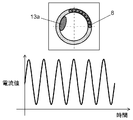
次に、ドラム3の周方向の偏心位置検知について説明する。本実施の形態では、偏心検知部20は、駆動モータ4に印加する電流値(トルク電流)と位相をモニターしている。偏心位置は変動する電流の周期より得ている。
Next, the detection of the eccentric position in the circumferential direction of the drum 3 will be described. In the present embodiment, the eccentricity detection unit 20 monitors the current value (torque current) and phase applied to the drive motor 4. The eccentric position is obtained from the period of the fluctuating current.
回転するドラム3上でアンバランスが下方にあるときは、アンバランスを重量に逆らって上方に持ち上げることになるため、電流を多く消費し、電流検知部22が検知する電流値は増加する。逆に、アンバランスがドラム3の上部にあるときは、アンバランスを重力方向同じ下方に持っていくことになるため、最少の電流消費となる。このため、電流検知部22が検知する電流値は減少する。このように、ドラム3にアンバランスがあるときは、駆動モータ4の印加電流は変動し、印加電流はドラム3の回転時のアンバランスの位置とリンクする。また、アンバランスの量に比例して印加電流値も大きくなる。
When the unbalance is downward on the rotating drum 3, the unbalance is lifted upward against the weight, so that a large amount of current is consumed and the current value detected by the current detector 22 increases. On the contrary, when the unbalance is at the upper part of the drum 3, the unbalance is brought down in the same direction of gravity, so that the current consumption is minimized. For this reason, the current value detected by the current detector 22 decreases. Thus, when the drum 3 is unbalanced, the applied current of the drive motor 4 fluctuates, and the applied current is linked to the unbalanced position when the drum 3 is rotated. Also, the applied current value increases in proportion to the amount of unbalance.
図6Aは水槽のアンバランスが大きいときの駆動モータ電流の特性を示し、図6Bは水槽のアンバランスが小さいときの駆動モータ電流の特性を示す。図6Aに示すように、アンバランス量が大きければ、電流値の最大値または、電流変動値は大きくなる。図6Bに示すように、アンバランス量が小さければ、電流値の最大値または、電流変動値は小さくなる。よって上記電流値および電流変動値の大小で偏心量(アンバランス量)を決定することができる。
6A shows the characteristics of the drive motor current when the water tank imbalance is large, and FIG. 6B shows the characteristics of the drive motor current when the water tank imbalance is small. As shown in FIG. 6A, if the unbalance amount is large, the maximum current value or the current fluctuation value becomes large. As shown in FIG. 6B, if the unbalance amount is small, the maximum value of the current value or the current fluctuation value is small. Therefore, the amount of eccentricity (unbalance amount) can be determined by the magnitude of the current value and the current fluctuation value.
次に、図4を用いて共振回転速度までのドラム3の回転速度の立ち上げ方について説明する。
Next, how to increase the rotation speed of the drum 3 up to the resonance rotation speed will be described with reference to FIG.
まず、脱水動作が開始されると、ドラム3を80rpmまで上昇させて維持し、転動体8が環状容器17内の下部で回転せずに停止している状態にする(図4の(1))。そして、洗濯物13の偏心13aの位置と量の判定を行う。次に、制御部6aは、転動体8が水槽2の下部で留まっている状態からドラム3の回転を加速させる(図4のA点)。ドラム3の回転速度が上昇していくに従い、遠心力が増大して転動体8はドラム3と共に回転し始める(図4の(2))。制御部6aは加速中に水槽2全体の偏心量を検知している。転動体8と、洗濯物13の偏心13aとの位置が対向の位置からズレが大きくなるほど偏心量は大きくなり、水槽2は大きく振動する。制御部6aは、この偏心量の値が所定の閾値Xより大きいと判定した場合、閾値Xより小さくなるようにドラム3の回転の加速度を制御する(図4のB点)。そして、所定の閾値Xより小さくなった状態でドラム3の回転速度が共振回転速度を通過し、共振回転領域よりも高い回転速度まで一気に加速する。
First, when the dehydrating operation is started, the drum 3 is raised to 80 rpm and maintained so that the rolling element 8 is stopped without rotating at the lower part in the annular container 17 ((1) in FIG. 4). ). Then, the position and amount of the eccentric 13a of the laundry 13 are determined. Next, the control unit 6a accelerates the rotation of the drum 3 from the state where the rolling element 8 remains at the lower part of the water tank 2 (point A in FIG. 4). As the rotational speed of the drum 3 increases, the centrifugal force increases and the rolling element 8 starts to rotate together with the drum 3 ((2) in FIG. 4). The controller 6a detects the amount of eccentricity of the entire water tank 2 during acceleration. As the position of the rolling element 8 and the eccentricity 13a of the laundry 13 deviates from the opposite position, the amount of eccentricity increases and the water tank 2 vibrates greatly. When the controller 6a determines that the value of the eccentricity is greater than the predetermined threshold value X, the controller 6a controls the rotation acceleration of the drum 3 so as to be smaller than the threshold value X (point B in FIG. 4). Then, the rotational speed of the drum 3 passes through the resonant rotational speed in a state where the rotational speed is smaller than the predetermined threshold value X, and is accelerated to a rotational speed higher than the resonant rotational range.
また、ドラム回転の加速度を制御する場合、複数個の転動体8間で広がりを生じたり、洗濯物13の水分が遠心力によりドラム3の回転と共に減少したりして、アンバランス量が減少するなど、加速時点での情報だけでは転動体8を洗濯物13のアンバランス位置に対向する位置となるように制御できない場合がある。
In addition, when controlling the acceleration of drum rotation, the unbalance amount decreases due to the spread between the plurality of rolling elements 8, or the moisture in the laundry 13 decreasing with the rotation of the drum 3 due to centrifugal force. For example, the rolling element 8 may not be controlled to be in a position facing the unbalanced position of the laundry 13 only by information at the time of acceleration.
しかしながら、制御部6aは加速中に水槽2全体の偏心量を検知している。転動体8と洗濯物13のアンバランス位置が、対向する位置からのズレが大きくなるほど偏心量は大きくなり、水槽2は大きく振動する。制御部6aは、この偏心量の値が所定の閾値より小さくなるようにドラム回転の加速度を制御し、所定の閾値より小さくなった状態で共振回転速度を通過、共振回転領域よりも高い回転速度まで一気に加速する。このことにより、ドラムの振動を常に最少に抑えることができる。
However, the control unit 6a detects the amount of eccentricity of the entire water tank 2 during acceleration. The amount of eccentricity increases as the deviation from the position at which the rolling element 8 and the laundry 13 are unbalanced increases, and the aquarium 2 vibrates greatly. The control unit 6a controls the acceleration of the drum rotation so that the value of the eccentricity becomes smaller than a predetermined threshold, passes through the resonance rotation speed in a state of being smaller than the predetermined threshold, and has a rotation speed higher than the resonance rotation region. Accelerate all at once. As a result, the vibration of the drum can always be minimized.
(第2の実施の形態)
ドラムの回転速度の立ち上げ方の他の形態に関して説明する。 (Second Embodiment)
Another form of how to increase the rotation speed of the drum will be described.
ドラムの回転速度の立ち上げ方の他の形態に関して説明する。 (Second Embodiment)
Another form of how to increase the rotation speed of the drum will be described.
本発明の第2の実施の形態におけるドラム式洗濯機の制御部6aは、以下のような制御を行う。すなわち、制御部6aは、偏心検知部20によって得られた信号に基づき、加速前のドラム3の偏心量と偏心位置と、加速中のドラム3のアンバランスと転動体8とが共に回転する際の偏心量とから、ドラム加速中の各転動体すなわち転動体8の位置を判定する。そして、転動体8と洗濯物のアンバランスとが対向の位置になるように駆動モータを制御する。その他の構成は本発明の第1の実施の形態を援用する。以下、異なる点を説明する。
The control unit 6a of the drum type washing machine in the second embodiment of the present invention performs the following control. That is, when the controller 6a rotates the eccentric amount and eccentric position of the drum 3 before acceleration, the unbalance of the drum 3 during acceleration, and the rolling element 8 based on the signal obtained by the eccentricity detecting unit 20. The position of each rolling element during drum acceleration, that is, the rolling element 8 is determined from the amount of eccentricity. Then, the drive motor is controlled so that the rolling elements 8 and the unbalance of the laundry are in opposite positions. Other configurations use the first embodiment of the present invention. Hereinafter, different points will be described.
本発明の第1の実施の形態で示した通り、ドラム3の周方向におけるアンバランスの位置検知をする工程では、転動体8をドラム3の下部に留まらせることにより、ドラム3に張付く洗濯物13のアンバランス量とアンバランス位置とが判定できる。また、環状容器17内の転動体8の重量も既知である。次に、加速中のアンバランスは、遠心力の増加により、加速前よりもドラム3に張付くため、ドラム3の周方向において移動しない。よって加速中の偏心13aの位置は常に把握できる。また、転動体8の位置は、ドラム3の速度によるので、常に把握できる。
As shown in the first embodiment of the present invention, in the step of detecting the position of unbalance in the circumferential direction of the drum 3, the rolling element 8 stays at the lower part of the drum 3, thereby washing the drum 3. The unbalance amount and unbalance position of the object 13 can be determined. The weight of the rolling element 8 in the annular container 17 is also known. Next, since the unbalance during acceleration sticks to the drum 3 more than before acceleration due to an increase in centrifugal force, it does not move in the circumferential direction of the drum 3. Therefore, the position of the eccentric 13a during acceleration can always be grasped. Moreover, since the position of the rolling element 8 is based on the speed of the drum 3, it can always be grasped.
また、ドラム3の加速中のアンバランス量の減少は、偏心検知部20によるドラム3の振動変位や、電流検知部22により検知した駆動モータ4の電流値の減少から推測できる。そして、洗濯物13の偏心13aと転動体8のトータルのアンバランス量は、ドラム3の振動変位から判定できる。
Further, the decrease in the unbalance amount during acceleration of the drum 3 can be estimated from the vibration displacement of the drum 3 by the eccentricity detection unit 20 and the decrease in the current value of the drive motor 4 detected by the current detection unit 22. The total unbalance amount between the eccentric 13 a of the laundry 13 and the rolling element 8 can be determined from the vibration displacement of the drum 3.
さらに、加速中におけるドラム3の偏心位置、偏心量は、加速前の偏心13aの量と位置と、ドラム3の速度や加速度とから判定できる。加速中の転動体8の位置を判定すると、転動体8とアンバランスとが対向の位置になるようにドラム3の回転を制御することができる。以下、ドラムの回転速度の立ち上げ方の詳細を、図4を用いて説明する。
Further, the eccentric position and eccentric amount of the drum 3 during acceleration can be determined from the amount and position of the eccentric 13a before acceleration and the speed and acceleration of the drum 3. When the position of the accelerating rolling element 8 is determined, the rotation of the drum 3 can be controlled so that the rolling element 8 and the unbalance are opposed to each other. Details of how to increase the rotational speed of the drum will be described below with reference to FIG.
ドラム3を80rpmの一定回転速度に維持するまでは第1の実施の形態と同様である(図4の(1))。
It is the same as in the first embodiment until the drum 3 is maintained at a constant rotational speed of 80 rpm ((1) in FIG. 4).
次に、制御部6aは、転動体8が水槽2下部で留まっている状態からドラム3を加速させる(図4のA点)。ドラム3の回転速度が上昇していくに従い、遠心力が増大して転動体8はドラム3と共に回転し始める。この時、転動体8および洗濯物13の両方の影響により、ドラム3の動的バランスは取れていない場合がある(図4の(2))。
Next, the control unit 6a accelerates the drum 3 from the state where the rolling element 8 stays in the lower part of the water tank 2 (point A in FIG. 4). As the rotational speed of the drum 3 increases, the centrifugal force increases and the rolling element 8 starts to rotate together with the drum 3. At this time, the dynamic balance of the drum 3 may not be achieved due to the influence of both the rolling elements 8 and the laundry 13 ((2) in FIG. 4).
制御部6aは、80rpmの一定速度時に、アンバランス位置を検知しているため、加速開始時点での洗濯物13の偏心13aの位置を把握している。よって、ドラム回転速度から、加速中の任意の時間での洗濯物13の偏心13aの位置を推定することができる。また、加速開始時点での転動体8の位置は、予め回転速度に応じた転動体8の位置を記憶しておくことで、推定することができる。よって制御部6aは、加速回転中の任意の時点における転動体8と洗濯物13の偏心13aとの相対的位置関係を把握することができる。
Since the control unit 6a detects the unbalance position at a constant speed of 80 rpm, the controller 6a grasps the position of the eccentric 13a of the laundry 13 at the time of starting acceleration. Therefore, the position of the eccentric 13a of the laundry 13 at an arbitrary time during acceleration can be estimated from the drum rotation speed. Moreover, the position of the rolling element 8 at the time of starting acceleration can be estimated by storing the position of the rolling element 8 according to the rotational speed in advance. Therefore, the control part 6a can grasp | ascertain the relative positional relationship of the rolling element 8 and the eccentric 13a of the laundry 13 in the arbitrary time in acceleration rotation.
制御部6aは、転動体8と洗濯物13の偏心13aとが対向する位置からずれると、ドラム3全体としてのアンバランスが生じないように、転動体8と洗濯物13の偏心13aとが対向する位置になるように、駆動モータ4を制御する(図4のB)。この動作は、例えばドラム3の駆動モータ4の加速度を、短時間大きくしたり、小さくしたりすることにより、転動体8と洗濯物13の偏心13aとの位置関係を修正する。たとえばドラム3の回転方向に対して、転動体8より洗濯物13の偏心13aの方が相対的に遅れた位置にある場合は、ドラム3の駆動モータ4の加速度を一時的に大きくして対向の位置になるようにする。ドラム3の駆動モータ4の加速度を変えることにより、洗濯物13を転動体8に対して移動させることができる。そして、転動体8と洗濯物13の偏心13aとの位置関係をドラム3の共振回転速度通過時点で対向の位置に持っていくよう修正し、共振回転領域よりも高い回転速度まで一気に加速する。このように、アンバランスによる振動が大きくなるドラム共振回転速度で対向位置に持っていくことで振動を抑える(図4の(3))。
When the rolling element 8 and the eccentricity 13a of the laundry 13 are shifted from the position where the rolling element 8 and the eccentricity 13a of the laundry 13 are opposed to each other, the control unit 6a faces the eccentricity 13a of the rolling element 8 and the laundry 13 so The drive motor 4 is controlled so as to be in a position to perform (B in FIG. 4). This operation corrects the positional relationship between the rolling elements 8 and the eccentric 13a of the laundry 13 by increasing or decreasing the acceleration of the drive motor 4 of the drum 3 for a short time, for example. For example, when the eccentricity 13a of the laundry 13 is relatively delayed from the rolling element 8 with respect to the rotation direction of the drum 3, the acceleration of the driving motor 4 of the drum 3 is temporarily increased to oppose it. To be in the position. The laundry 13 can be moved relative to the rolling elements 8 by changing the acceleration of the drive motor 4 of the drum 3. Then, the positional relationship between the rolling element 8 and the eccentricity 13a of the laundry 13 is corrected so as to be brought to the opposite position when the drum 3 passes the resonance rotation speed, and the rotation speed is accelerated to a higher rotation speed than the resonance rotation area. In this way, the vibration is suppressed by bringing it to the opposite position at the drum resonance rotation speed at which the vibration due to unbalance increases ((3) in FIG. 4).
第1の実施の形態では、偏心量が閾値Xよりも大きいときにドラム3の加速度を変更することとした。これに対して、本実施の形態においては、転動体8と洗濯物13の偏心13aの位置を把握し、推定することにより、偏心量が閾値Xにならないように共振回転速度までドラム3の回転速度を立ち上げることが出来る。よって、共振回転速度になる前にも大きな振動を起こすことなく、スムーズにドラム3の回転速度を立ち上げることができる。
In the first embodiment, the acceleration of the drum 3 is changed when the amount of eccentricity is larger than the threshold value X. On the other hand, in the present embodiment, the drum 3 is rotated up to the resonance rotational speed so that the eccentric amount does not become the threshold value X by grasping and estimating the position of the eccentricity 13a of the rolling element 8 and the laundry 13. Can speed up. Therefore, the rotational speed of the drum 3 can be raised smoothly without causing large vibrations even before reaching the resonant rotational speed.
また、ドラム3の回転の加速度を制御する場合、複数個の転動体8間で広がりを生じたり、洗濯物13の水分が遠心力によりドラム3の回転と共に減少したりしてアンバランス量が減少するなど、加速時点での情報だけでは転動体8と洗濯物13を対向する位置に制御できない場合がある。
Further, when controlling the rotation acceleration of the drum 3, the unbalance amount is reduced due to the spread between the plurality of rolling elements 8, or the moisture in the laundry 13 is reduced with the rotation of the drum 3 due to the centrifugal force. In some cases, the rolling element 8 and the laundry 13 cannot be controlled to face each other only by information at the time of acceleration.
しかしながら、本実施の形態では、制御部6aは加速中に水槽2全体の偏心量を検知している。転動体8と洗濯物13の偏心13aが対向する位置からのズレが大きくなるほど偏心量は大きくなり、水槽2は大きく振動する。そこで、制御部6aは、この偏心量の値が所定の閾値より小さくなるようにドラム3の回転の加速度を制御する。電流検知部22が検知した電流値または電流値の変動量が所定の閾値より小さくなった状態で、共振回転領域よりも高い回転速度まで一気に加速する。これにより、共振回転速度域の通過時には大きな振動が発生することがなく、脱水工程を行うことができる。
However, in the present embodiment, the control unit 6a detects the eccentric amount of the entire water tank 2 during acceleration. As the displacement from the position where the rolling element 8 and the eccentric 13a of the laundry 13 are opposed to each other increases, the amount of eccentricity increases and the water tank 2 vibrates greatly. Therefore, the control unit 6a controls the acceleration of the rotation of the drum 3 so that the value of the eccentricity becomes smaller than a predetermined threshold value. In a state in which the current value detected by the current detection unit 22 or the fluctuation amount of the current value is smaller than a predetermined threshold value, the acceleration is accelerated to a rotational speed higher than the resonance rotational region. Thereby, a big vibration does not generate | occur | produce at the time of passing through a resonance rotational speed range, but a dehydration process can be performed.
この構成により、ドラム3の加速中の転動体8の位置を解析により判定することができるため、転動体8と洗濯物13の偏心13aが対向する位置に、早期にかつ精度よくドラム3を制御することができる。このため、共振回転通過前後で大きくなるドラム3の振動を広範囲に最小限に抑えることができる。
With this configuration, since the position of the rolling element 8 during acceleration of the drum 3 can be determined by analysis, the drum 3 can be controlled quickly and accurately at a position where the rolling element 8 and the eccentric 13a of the laundry 13 face each other. can do. For this reason, the vibration of the drum 3 which becomes large before and after passing through the resonance rotation can be minimized over a wide range.
(第3の実施の形態)
以下、本発明の第3の実施の形態におけるドラム式洗濯機の動作、作用について図7を用いて説明する。 (Third embodiment)
Hereinafter, operation | movement and an effect | action of the drum type washing machine in the 3rd Embodiment of this invention are demonstrated using FIG.
以下、本発明の第3の実施の形態におけるドラム式洗濯機の動作、作用について図7を用いて説明する。 (Third embodiment)
Hereinafter, operation | movement and an effect | action of the drum type washing machine in the 3rd Embodiment of this invention are demonstrated using FIG.
なお、本発明の第1および第2の実施の形態と同じ構成要素については、同じ番号を付して説明するとともに詳細な説明は省略する。
In addition, about the same component as the 1st and 2nd embodiment of this invention, it attaches | subjects and demonstrates the same number, and abbreviate | omits detailed description.
図7は、本発明の第3の実施の形態におけるドラム式洗濯機の回転速度のシーケンスを表す図である。
FIG. 7 is a diagram showing a rotation speed sequence of the drum-type washing machine according to the third embodiment of the present invention.
まず、ドラム式洗濯機1が排水後に脱水を行う場合、制御部6aの指令により駆動モータ4に駆動電圧を印加させる。駆動モータ4を低速回転から高速回転に動作させ、ドラム3の回転速度を徐々に上昇させる。このとき、駆動モータ4が永久磁石同期モータであるため、駆動モータ4のロータ位置を検知する。これにより、駆動モータ4の脱調を防止することで安全、かつ高速に回転速度を上昇させることができる。
First, when the drum-type washing machine 1 performs dehydration after draining, a drive voltage is applied to the drive motor 4 according to a command from the control unit 6a. The drive motor 4 is operated from low speed rotation to high speed rotation, and the rotation speed of the drum 3 is gradually increased. At this time, since the drive motor 4 is a permanent magnet synchronous motor, the rotor position of the drive motor 4 is detected. Thereby, it is possible to increase the rotational speed safely and at high speed by preventing the drive motor 4 from stepping out.
次に、制御部6aは、洗濯物13や転動体8にかかる重力がドラム3の回転による遠心力より小さい回転速度までドラム3の回転速度を上げて維持する(図7の(1))。
Next, the controller 6a increases and maintains the rotational speed of the drum 3 to a rotational speed at which the gravity applied to the laundry 13 and the rolling element 8 is smaller than the centrifugal force generated by the rotation of the drum 3 ((1) in FIG. 7).
以上のようにして、制御部6aは、転動体8が環状容器17の下部で留まる状態にし、洗濯物13の偏心13aの位置と量の判定を行う。そして、転動体8に対して対向する位置に洗濯物13の偏心13aが位置した時にドラムを共振回転速度よりも高い回転速度まで一気に加速する(図7のA点)。転動体8は、ドラム3の回転に伴い、多少回転方向側に移動して留まるので、洗濯物13のアンバランス位置がドラム3上方で、かつ回転方向側に位置したときに、制御部6aはドラム3を加速させる(図7の(2))。
As described above, the control unit 6a makes the rolling element 8 stay in the lower part of the annular container 17, and determines the position and amount of the eccentric 13a of the laundry 13. And when the eccentric 13a of the laundry 13 is located in the position facing the rolling element 8, the drum is accelerated at a stretch to a rotational speed higher than the resonant rotational speed (point A in FIG. 7). As the rolling element 8 rotates, the rolling element 8 moves slightly to the rotational direction side, so that when the unbalanced position of the laundry 13 is located above the drum 3 and on the rotational direction side, the control unit 6a The drum 3 is accelerated ((2) in FIG. 7).
以上のようにして、共振回転速度より前の段階であるドラム3の加速時に、洗濯物の偏心と転動体8を対抗する位置に配置することにより、ドラム3の振動が大きくなるドラム共振回転速度での振動を抑えることができる。
As described above, when the drum 3 is accelerated before the resonance rotation speed, the drum resonance vibration speed at which the vibration of the drum 3 is increased by arranging the laundry eccentricity and the rolling element 8 at a position facing each other. The vibration at can be suppressed.
なお、衣類のアンバランス量が転動体8のアンバランス補正量より小さい場合、洗濯物13の偏心13aの位置に対して、お互い接触した状態の複数個の転動体8対向の位置で立ち上げると、かえって転動体自身がドラム3の回転におけるアンバランスとなり、結果としてドラム3の振動変位は大きくなってしまう。
In addition, when the unbalance amount of clothing is smaller than the unbalance correction amount of the rolling element 8, if the clothes 13 are started up at positions facing the plurality of rolling elements 8 in contact with each other with respect to the position of the eccentric 13 a of the laundry 13. On the contrary, the rolling element itself becomes unbalanced in the rotation of the drum 3, and as a result, the vibration displacement of the drum 3 becomes large.
よって、80rpmで衣類のアンバランス量を判定した時に、衣類のアンバランス量が転動体のアンバランス補正量より小さい場合には、複数個の転動体8をお互い接触した状態から環状容器17全体に点在させた状態になるようにドラム3の回転を制御する。これによって、転動体8自身の回転時のアンバランス量を低くさせた上でドラム3を共振回転速度よりも高い回転速度まで一気に加速させる。この制御により、衣類の偏心量が少ない時でも共振回転速度前後でのドラム振動を抑制することができる。
Therefore, when the unbalance amount of the clothing is determined at 80 rpm and the unbalance amount of the clothing is smaller than the unbalance correction amount of the rolling elements, the plurality of rolling elements 8 are brought into contact with each other from the contacted state to the entire annular container 17. The rotation of the drum 3 is controlled so as to be in a scattered state. As a result, the unbalance amount during rotation of the rolling element 8 itself is lowered, and the drum 3 is accelerated at a stretch to a rotational speed higher than the resonance rotational speed. This control can suppress drum vibration around the resonance rotational speed even when the amount of eccentricity of the garment is small.
(第4の実施の形態)
ドラムの回転速度の立ち上げ方の他の形態に関して説明する。 (Fourth embodiment)
Another form of how to increase the rotation speed of the drum will be described.
ドラムの回転速度の立ち上げ方の他の形態に関して説明する。 (Fourth embodiment)
Another form of how to increase the rotation speed of the drum will be described.
図8は、本発明の第4の実施の形態におけるドラム式洗濯機の回転速度のシーケンスを表す図である。上記第3の実施の形態とは、ドラム3を加速させるタイミングが異なる。
FIG. 8 is a diagram showing a rotation speed sequence of the drum type washing machine according to the fourth embodiment of the present invention. The timing for accelerating the drum 3 is different from that of the third embodiment.
本実施の形態において制御部6aは、ドラム3内の洗濯物が落下せず、かつ、転動体8がドラム3の下部に留まる回転速度にてドラム3を回転させた状態(図8の(1))で、偏心検知部20により検知した洗濯物の偏心位置を解析し、洗濯物13の偏心13aの位置が回転軸31より上部にあるときにドラム3を加速させるものである。その他の構成は第3の実施の形態を援用する。以下、異なる点を説明する。
In the present embodiment, the control unit 6a rotates the drum 3 at a rotational speed at which the laundry in the drum 3 does not fall and the rolling element 8 stays below the drum 3 ((1 in FIG. 8). )), The eccentric position of the laundry detected by the eccentricity detection unit 20 is analyzed, and the drum 3 is accelerated when the position of the eccentric 13a of the laundry 13 is above the rotary shaft 31. The other configuration uses the third embodiment. Hereinafter, different points will be described.
ドラム3の回転速度を80rpmにて維持する(図8の(1))。このとき、転動体8はドラム3の下部で留まっている。洗濯物13の偏心13aがドラム3の上部に位置したときにドラム3を加速すれば、転動体8がドラム3の下部で留まっているので、洗濯物の13の偏心13aと転動体8とを対向する状態にすることができる。よって、制御部6aは、偏心検知部20により洗濯物13の偏心13aの位置を検知し、洗濯物13の偏心13aがドラム3の上部にあるときにドラム3を加速させる。これによって、ドラム3自体のアンバランスがほとんどないので、この状態で共振回転速度まで一気にドラム3の回転速度を上昇させる(図8のA点)(図8の(2))。この構成により、駆動モータ4の加速中の転動体8の位置を解析により判定することができるため、洗濯物13の偏心13aと転動体8とが対向する位置に、早期にかつ精度よくドラム3の回転を制御することができる。このため、共振回転通過前後で大きくなるドラムの振動を広範囲に最小限に抑えることができる。
The rotation speed of the drum 3 is maintained at 80 rpm ((1) in FIG. 8). At this time, the rolling element 8 remains at the lower part of the drum 3. If the drum 3 is accelerated when the eccentric 13a of the laundry 13 is positioned at the upper part of the drum 3, the rolling element 8 stays at the lower part of the drum 3, so the eccentric 13a of the laundry 13 and the rolling element 8 are It can be in an opposing state. Therefore, the control unit 6a detects the position of the eccentricity 13a of the laundry 13 by the eccentricity detection unit 20, and accelerates the drum 3 when the eccentricity 13a of the laundry 13 is above the drum 3. As a result, there is almost no unbalance of the drum 3 itself, and in this state, the rotational speed of the drum 3 is increased all at once to the resonance rotational speed (point A in FIG. 8) ((2) in FIG. 8). With this configuration, since the position of the rolling element 8 during acceleration of the drive motor 4 can be determined by analysis, the drum 3 can be quickly and accurately positioned at a position where the eccentric 13a of the laundry 13 and the rolling element 8 face each other. Can be controlled. For this reason, the vibration of the drum that becomes large before and after passing through the resonance rotation can be minimized over a wide range.
以上のように、発明のドラム式洗濯機は、水平または傾斜した回転軸にて回転可能に支持された有底円筒状のドラムと、ドラムを収容する水槽と、ドラムを駆動する駆動モータと、ドラムと一体に設けられた環状容器と、環状容器の内部に移動自在に収容された複数の転動体を有する。さらに、ドラムの回転時に、ドラム内の洗濯物の偏りや転動体によって生じるドラムの偏心状態を検知する偏心検知部と、偏心検知部により検知した偏心位置を解析するとともに駆動モータを制御する制御部とを備える。そして、制御部が、ドラム内の洗濯物が落下せず、かつ、転動体がドラム下部に留まる回転速度にてドラムを回転させた状態で、偏心検知部によりドラムの偏心状態を検知する。
As described above, the drum-type washing machine of the invention is a bottomed cylindrical drum that is rotatably supported by a horizontal or inclined rotating shaft, a water tank that houses the drum, a drive motor that drives the drum, An annular container provided integrally with the drum, and a plurality of rolling elements movably accommodated inside the annular container. Further, when the drum rotates, an eccentricity detection unit that detects the eccentricity of the laundry in the drum and the eccentric state of the drum caused by the rolling elements, and a control unit that analyzes the eccentric position detected by the eccentricity detection unit and controls the drive motor With. Then, the control unit detects the eccentric state of the drum by the eccentricity detection unit in a state where the laundry in the drum does not fall and the drum is rotated at a rotation speed at which the rolling elements stay below the drum.
この構成により、洗濯物はドラムに張りつくが転動体はドラムとともに回転せずにドラム下部で停止させた状態を作り出すことができ、洗濯物のみのアンバランス位置を精度よく検知することができる。このため、洗濯物のアンバランス状態に応じてドラムを制御しやすくなり、ドラムを高速回転させる時の騒音、振動を抑えることができる。
With this configuration, it is possible to create a state in which the laundry sticks to the drum but the rolling element does not rotate with the drum and is stopped at the bottom of the drum, and the unbalanced position of the laundry alone can be detected with high accuracy. For this reason, it becomes easy to control the drum according to the unbalanced state of the laundry, and noise and vibration when the drum is rotated at high speed can be suppressed.
また、本発明は、ドラムの偏心位置を検知し、制御部は、偏心検知部によりドラムの偏心状態を検知した後、ドラムを加速させ、ドラムの回転速度が共振回転速度を通過する時に、ドラムの偏心位置が転動体と対向の位置になるように駆動モータを制御する。
In the present invention, the eccentric position of the drum is detected, and the control unit detects the eccentric state of the drum by the eccentricity detection unit and then accelerates the drum, and the drum rotates when the drum rotation speed passes the resonance rotation speed. The drive motor is controlled so that the eccentric position of is opposite to the rolling element.
この構成により、洗濯物はドラムに張りつくが転動体はドラムとともに回転せずにドラム下部で停止させた状態を作り出すことができ、洗濯物のみのアンバランス位置を検知することができる。そして、ドラムの加速開始時の転動体とアンバランスとの位置関係から、ドラム加速中に駆動モ-タを制御し、共振回転速度通過時点でアンバランスと転動体とが対向の相対位置関係になるようにできるため、共振回転速度通過時点でのドラムの振動を最小限に抑えることができる。
With this configuration, it is possible to create a state where the laundry sticks to the drum but the rolling element does not rotate with the drum and is stopped at the bottom of the drum, and the unbalance position of the laundry alone can be detected. Then, based on the positional relationship between the rolling element and the unbalance when the drum starts accelerating, the drive motor is controlled during the drum acceleration, and the unbalanced and the rolling element are in a relative positional relationship facing each other when the resonance rotational speed is passed. Therefore, the vibration of the drum when the resonance rotational speed passes can be minimized.
また、本発明は、ドラムの偏心量を検知し、制御部が、ドラムの加速動作中に、ドラムの偏心量が所定の閾値より大きいと検知したとき、ドラムの偏心量が所定の閾値よりも小さくなるように駆動モータを制御する。
Further, the present invention detects the amount of eccentricity of the drum, and when the control unit detects that the amount of eccentricity of the drum is larger than a predetermined threshold during the acceleration operation of the drum, the amount of eccentricity of the drum is less than the predetermined threshold. The drive motor is controlled to be small.
この構成により、ドラムを加速中にドラムの偏心量を検出できるため、転動体が広がったり、洗濯物の状態変化によりアンバランス量が変化したりした場合でも、それに応じてドラムの回転制御を行うことで転動体とアンバランスとが対向の位置になるように制御できる。このため、ドラムの振動を常に最少に抑えることができる。
With this configuration, since the amount of eccentricity of the drum can be detected while accelerating the drum, even if the rolling element spreads or the unbalance amount changes due to a change in the state of the laundry, the rotation of the drum is controlled accordingly. Thus, the rolling element and the unbalance can be controlled so as to face each other. For this reason, the vibration of the drum can always be minimized.
また、本発明は、ドラム加速前のドラムの偏心位置と、転動体の位置とにより、共振回転速度までのドラムの加速度を決定して、ドラムの回転速度が共振回転速度を通過する時に、各転動体と洗濯物のアンバランスとが対向の位置になるように駆動モータを制御するものである。
Further, the present invention determines the drum acceleration up to the resonance rotational speed based on the eccentric position of the drum before the drum acceleration and the position of the rolling element, and when the drum rotation speed passes the resonance rotation speed, The drive motor is controlled so that the rolling elements and the unbalance of the laundry are in opposite positions.
この構成により、ドラム加速中の洗濯物のアンバランスと転動体とを対向する位置に持っていく制御を早期にかつ精度よく行うことができため、共振回転速度通過前後で大きくなるドラムの振動を広範囲に最小限に抑えることができる。
With this configuration, the control of bringing the unbalanced laundry and the rolling elements to the opposite positions during acceleration of the drum can be performed quickly and accurately. Can be minimized over a wide range.
また、本発明のドラム式洗濯機は、制御部が、ドラム内の洗濯物が落下せず、かつ、転動体がドラムの下部に留まる回転速度にてドラムを回転させた状態で、偏心検知部により検知した洗濯物の偏心位置を解析する。その後にドラムを加速させて、共振回転速度よりも低い回転速度で、転動体と洗濯物の偏心位置が対向する状態でドラムと転動体が一体で回転するように駆動モータを制御する。
In the drum type washing machine of the present invention, the controller detects the eccentricity in a state in which the laundry in the drum does not fall and the drum is rotated at a rotational speed at which the rolling element stays below the drum. The eccentric position of the laundry detected by is analyzed. Thereafter, the drum is accelerated, and the drive motor is controlled so that the drum and the rolling element rotate integrally at a rotational speed lower than the resonance rotational speed with the eccentric position of the rolling element and the laundry facing each other.
この構成により、ドラムは回転するが、転動体はドラム下部で留まり共回りしない状態にすることができる。この状態では、ドラムの揺れはドラムと共に回転する衣類のアンバランスにより起こるものであり、ドラムの振動変動から衣類のみのアンバランス量を検知することができる。また、アンバランスが回転することで、モータは回転時にトルク変動する。解析部は、その変動周期からアンバランス位置を解析する。そして、アンバランスがドラム上部に位置するときと、モータのトルク変動が極大を示すところが一致することから、この時点ではアンバランスと転動体とが逆位相の相対位置関係にある。そこで、アンバランスが極大点に来たところでモータを加速すれば、共振回転速度通過時にはドラムの振動を抑えることができる。
This configuration allows the drum to rotate, but the rolling element stays at the bottom of the drum and does not rotate together. In this state, the vibration of the drum is caused by the imbalance of the clothes rotating together with the drum, and the unbalance amount of only the clothes can be detected from the vibration fluctuation of the drum. Further, when the unbalance rotates, the torque of the motor varies during rotation. The analysis unit analyzes the unbalance position from the fluctuation period. Then, when the unbalance is located at the upper part of the drum, the position where the torque fluctuation of the motor shows the maximum coincides, and at this time, the unbalance and the rolling element are in a relative positional relationship of opposite phases. Therefore, if the motor is accelerated when the imbalance reaches the maximum point, the vibration of the drum can be suppressed when the resonance rotational speed is passed.
また、本発明のドラム式洗濯機は、制御部が、ドラム内の洗濯物が落下せず、かつ、転動体がドラムの下部に留まる回転速度にてドラムを回転させた状態で、偏心検知部により検知した洗濯物の偏心位置を解析し、洗濯物の偏心位置が回転軸より上部にあるときにドラムを加速させる。
In the drum type washing machine of the present invention, the controller detects the eccentricity in a state in which the laundry in the drum does not fall and the drum is rotated at a rotational speed at which the rolling element stays below the drum. The eccentric position of the laundry detected by the above is analyzed, and the drum is accelerated when the eccentric position of the laundry is above the rotation axis.
この構成により、ドラムは回転するが、転動体はドラム下部で留まり共回りしない状態にすることができる。この状態では、ドラムの揺れはドラムと共に回転する衣類のアンバランスにより起こるものであり、ドラムの振動変動から衣類のみのアンバラ量を検知することができる。また、アンバラが回転することで、モータは回転時にトルク変動する。解析部は、その変動周期からアンバラ位置を解析する。そして、アンバラがドラム上部に位置するときと、モータのトルク変動が極大を示すところが一致することから、この時点ではアンバランスと転動体とが逆位相の相対位置関係にある。そこで、アンバランスが極大点に来たところ、すなわち、アンバランスがドラム上部に位置するときにドラムを加速すれば、共振回転速度通過時にはドラムの振動を抑えることができる。
This configuration allows the drum to rotate, but the rolling element stays at the bottom of the drum and does not rotate together. In this state, the swing of the drum is caused by the imbalance of the clothes rotating together with the drum, and the unbalance amount of only the clothes can be detected from the vibration fluctuation of the drum. In addition, the unvarying rotation causes the motor to undergo torque fluctuations during rotation. The analysis unit analyzes the unbalanced position from the fluctuation period. Since the position where the torque fluctuation of the motor shows the maximum coincides with the time when the uncrowd is located at the upper part of the drum, at this time, the unbalance and the rolling element are in a relative positional relationship of opposite phases. Therefore, if the drum is accelerated when the unbalance reaches the maximum point, that is, when the unbalance is located above the drum, vibration of the drum can be suppressed when the resonance rotational speed is passed.
また、本発明は、制御部が、偏心検知部により検知したドラムの偏心位置を解析するとともに、ドラムの偏心位置と転動体とが対向になる位置でドラムを加速させて共振点を通過させる制御を行う。
Further, according to the present invention, the control unit analyzes the eccentric position of the drum detected by the eccentricity detection unit, and controls to accelerate the drum at a position where the eccentric position of the drum and the rolling element face each other and pass the resonance point. I do.
この構成により、簡単な検知と制御でドラムのアンバランスを低減して、ドラムの回転速度を共振回転速度に到達させることができる。
This configuration reduces drum imbalance with simple detection and control, and allows the drum rotation speed to reach the resonance rotation speed.
また、本発明は、ドラムの振動を検知する振動検知部をさらに備えたものである。
Further, the present invention further includes a vibration detection unit that detects the vibration of the drum.
この構成により、ドラム回転中に複数個の転動体同士が分散したり、衣類のアンバランス状態が変化したりすることでアンバランス位置を解析できない場合でも、ドラムの振動変位を検知できる。そのため、共振回転速度に到達するまでにドラム回転を加速、減速することでドラムの振動変位をより抑える制御を行い、共振回転速度通過時にはドラムの振動を最小限に抑えることができる。
This configuration can detect the vibration displacement of the drum even when the unbalanced position cannot be analyzed due to the fact that a plurality of rolling elements are dispersed while the drum is rotating or the unbalanced state of the clothing changes. Therefore, the drum rotation is accelerated and decelerated until the resonance rotational speed is reached, so that the vibration displacement of the drum can be further controlled, and the drum vibration can be minimized when the resonance rotational speed is passed.
本発明にかかるドラム式洗濯機は、アンバランスに対して転動体が振動抑制効果を得られるようにドラムの回転速度を立ち上げることができるため、アンバランスをより低減することができる。そのため、起動時の振動を抑制できることから、家庭用、業務用のドラム式洗濯機やクリーニング装置として有用である。
The drum type washing machine according to the present invention can increase the rotation speed of the drum so that the rolling element can obtain a vibration suppressing effect against the unbalance, and therefore can further reduce the unbalance. Therefore, since vibration at the time of activation can be suppressed, it is useful as a drum-type washing machine or a cleaning device for home use or business use.
1 ドラム式洗濯機
2 水槽
3,101 ドラム
4 駆動モータ
5 ダンパ
6a 制御部
8,103 転動体
10 バネ
12 振動検知部
13 洗濯物
16 バッフル
17,102 環状容器
18 粘性流体
20 偏心検知部
22 電流検知部
30,104 ボールバランサ
31 回転軸 DESCRIPTION OFSYMBOLS 1 Drum type washing machine 2 Water tank 3,101 Drum 4 Drive motor 5 Damper 6a Control part 8,103 Rolling body 10 Spring 12 Vibration detection part 13 Laundry 16 Baffle 17,102 Annular container 18 Viscous fluid 20 Eccentricity detection part 22 Current detection Part 30, 104 Ball balancer 31 Rotating shaft
2 水槽
3,101 ドラム
4 駆動モータ
5 ダンパ
6a 制御部
8,103 転動体
10 バネ
12 振動検知部
13 洗濯物
16 バッフル
17,102 環状容器
18 粘性流体
20 偏心検知部
22 電流検知部
30,104 ボールバランサ
31 回転軸 DESCRIPTION OF
Claims (7)
- 水平または傾斜した回転軸にて回転可能に支持された有底円筒状のドラムと、
前記ドラムを収容する水槽と、
前記ドラムを駆動する駆動モータと、
前記ドラムと一体に設けられた環状容器と、
前記環状容器の内部に移動自在に収容された複数の転動体と、
前記ドラムの回転時に、前記ドラム内の洗濯物の偏りや前記転動体によって生じる前記ドラムの偏心状態を検知する偏心検知部と、
前記駆動モータを制御する制御部と、を備え、
前記制御部は、
前記ドラム内の洗濯物が落下せず、かつ、前記転動体が前記ドラム下部に留まる回転速度にて前記ドラムを回転させた状態で、前記偏心検知部により前記ドラムの偏心状態を検知するドラム式洗濯機。 A bottomed cylindrical drum rotatably supported on a horizontal or inclined rotating shaft;
A water tank containing the drum;
A drive motor for driving the drum;
An annular container provided integrally with the drum;
A plurality of rolling elements movably accommodated in the annular container;
An eccentricity detecting unit for detecting the eccentricity of the laundry in the drum and the eccentric state of the drum caused by the rolling elements during rotation of the drum;
A control unit for controlling the drive motor,
The controller is
A drum type that detects the eccentric state of the drum by the eccentricity detecting unit in a state where the laundry in the drum does not fall and the drum is rotated at a rotational speed at which the rolling element stays at the lower part of the drum. Washing machine. - 前記制御部は、前記ドラムの偏心状態を検知した後、前記ドラムを加速させて、共振回転速度よりも低い回転速度で、前記転動体と洗濯物の偏心位置が対向する状態で前記ドラムと前記転動体とが一体で回転するように前記駆動モータを制御する請求項1に記載のドラム式洗濯機。 The controller, after detecting the eccentric state of the drum, accelerates the drum and rotates the drum and the laundry in a state where the eccentric position of the rolling element and the laundry face each other at a rotational speed lower than a resonant rotational speed. The drum type washing machine according to claim 1, wherein the driving motor is controlled so that the rolling element rotates integrally with the rolling element.
- 前記制御部は、洗濯物の偏心位置が前記回転軸より上部にあるときに前記ドラムを加速させる請求項1に記載のドラム式洗濯機。 The drum-type washing machine according to claim 1, wherein the control unit accelerates the drum when an eccentric position of the laundry is above the rotation shaft.
- 前記制御部は、
前記偏心検知部により前記ドラムの偏心状態を検知した後、前記ドラムを加速させ、前記ドラムの回転速度が共振回転速度を通過する時に、前記ドラムの偏心位置が前記転動体と対向の位置になるように前記駆動モータを制御する請求項1に記載のドラム式洗濯機。 The controller is
After detecting the eccentric state of the drum by the eccentricity detecting unit, the drum is accelerated, and the eccentric position of the drum is opposed to the rolling element when the rotational speed of the drum passes the resonance rotational speed. The drum type washing machine according to claim 1, wherein the driving motor is controlled as described above. - 前記偏心検知部は、前記ドラムの偏心量を検知し、
前記制御部は、前記偏心検知部により前記ドラムの偏心状態を検知した後、前記ドラムを加速させ、前記ドラムの加速動作中に、前記ドラムの偏心量が所定の閾値より大きいと検知したとき、前記ドラムの偏心量が前記所定の閾値よりも小さくなるように前記駆動モータを制御する請求項1に記載のドラム式洗濯機。 The eccentricity detection unit detects the amount of eccentricity of the drum,
The controller, after detecting the eccentric state of the drum by the eccentricity detector, when accelerating the drum, and detecting that the eccentric amount of the drum is larger than a predetermined threshold during the acceleration operation of the drum, The drum type washing machine according to claim 1, wherein the drive motor is controlled so that an eccentric amount of the drum is smaller than the predetermined threshold value. - 前記制御部は、前記ドラムの偏心位置と前記転動体とが対向になる位置で前記ドラムを加速させて共振点を通過させる制御を行う請求項1に記載のドラム式洗濯機。 2. The drum type washing machine according to claim 1, wherein the control unit performs control of accelerating the drum at a position where the eccentric position of the drum and the rolling element face each other to pass a resonance point. 3.
- 前記ドラムの振動を検知する振動検知部をさらに備えた請求項1に記載のドラム式洗濯機。 The drum-type washing machine according to claim 1, further comprising a vibration detection unit that detects vibration of the drum.
Priority Applications (2)
| Application Number | Priority Date | Filing Date | Title |
|---|---|---|---|
| DE112013002158.7T DE112013002158T5 (en) | 2012-04-23 | 2013-04-22 | Drum-type washing machine |
| CN201380021535.0A CN104246050B (en) | 2012-04-23 | 2013-04-22 | Tumbling-box washing machine |
Applications Claiming Priority (4)
| Application Number | Priority Date | Filing Date | Title |
|---|---|---|---|
| JP2012097378A JP2013223622A (en) | 2012-04-23 | 2012-04-23 | Drum type washing machine |
| JP2012-097378 | 2012-04-23 | ||
| JP2012-097377 | 2012-04-23 | ||
| JP2012097377A JP2013223621A (en) | 2012-04-23 | 2012-04-23 | Drum type washing machine |
Publications (1)
| Publication Number | Publication Date |
|---|---|
| WO2013161252A1 true WO2013161252A1 (en) | 2013-10-31 |
Family
ID=49482598
Family Applications (1)
| Application Number | Title | Priority Date | Filing Date |
|---|---|---|---|
| PCT/JP2013/002678 WO2013161252A1 (en) | 2012-04-23 | 2013-04-22 | Drum type washing machine |
Country Status (3)
| Country | Link |
|---|---|
| CN (1) | CN104246050B (en) |
| DE (1) | DE112013002158T5 (en) |
| WO (1) | WO2013161252A1 (en) |
Cited By (4)
| Publication number | Priority date | Publication date | Assignee | Title |
|---|---|---|---|---|
| JP2019092706A (en) * | 2017-11-21 | 2019-06-20 | 青島海爾洗衣机有限公司QingDao Haier Washing Machine Co.,Ltd. | Drum type washing machine |
| JP2019115504A (en) * | 2017-12-27 | 2019-07-18 | 青島海爾洗衣机有限公司QingDao Haier Washing Machine Co.,Ltd. | Washing machine |
| CN113825871A (en) * | 2019-05-23 | 2021-12-21 | 青岛海尔洗衣机有限公司 | Drum washing machine |
| JP7352410B2 (en) | 2019-08-20 | 2023-09-28 | 株式会社ヒラノテクシード | Eccentricity detection device, eccentricity adjustment device, and coating device |
Families Citing this family (8)
| Publication number | Priority date | Publication date | Assignee | Title |
|---|---|---|---|---|
| US10024597B2 (en) * | 2014-11-26 | 2018-07-17 | Extractor Corporation | Centrifugal separator |
| JP6507367B2 (en) * | 2015-04-09 | 2019-05-08 | パナソニックIpマネジメント株式会社 | Drum type washing machine |
| JP7061754B2 (en) * | 2016-12-27 | 2022-05-02 | 青島海爾洗衣机有限公司 | Washing machine |
| JP7061755B2 (en) * | 2016-12-27 | 2022-05-02 | 青島海爾洗衣机有限公司 | Drum type washing machine |
| JP7218853B2 (en) * | 2018-07-13 | 2023-02-07 | 青島海爾洗衣机有限公司 | drum washing machine |
| DE102019213015A1 (en) * | 2019-08-29 | 2021-03-04 | BSH Hausgeräte GmbH | Laundry care device with one control |
| CN113417111B (en) * | 2021-07-23 | 2022-03-29 | 珠海格力电器股份有限公司 | Washing machine and control method |
| CN113463332B (en) * | 2021-08-02 | 2022-04-26 | 珠海格力电器股份有限公司 | Washing machine control method and washing machine |
Citations (2)
| Publication number | Priority date | Publication date | Assignee | Title |
|---|---|---|---|---|
| US20080105002A1 (en) * | 2006-11-06 | 2008-05-08 | Samsung Electronics Co., Ltd. | Washing machine and method of controlling the same |
| US20080172805A1 (en) * | 2007-01-24 | 2008-07-24 | Samsung Electronics Co., Ltd. | Washing machine with balancers and control method thereof |
Family Cites Families (4)
| Publication number | Priority date | Publication date | Assignee | Title |
|---|---|---|---|---|
| KR100224450B1 (en) * | 1996-05-23 | 1999-10-15 | 윤종용 | Balancing apparatus of a drum washing machine |
| JP3625791B2 (en) * | 2001-09-13 | 2005-03-02 | 三洋電機株式会社 | Drum washing machine |
| CN1683631A (en) * | 2004-04-12 | 2005-10-19 | 乐金电子(天津)电器有限公司 | Control method for dewatering of rolling drum washing machine |
| CN101962901B (en) * | 2009-07-22 | 2014-01-08 | 海尔集团公司 | Gimbal device of rolling drum-type washing machine |
-
2013
- 2013-04-22 CN CN201380021535.0A patent/CN104246050B/en active Active
- 2013-04-22 DE DE112013002158.7T patent/DE112013002158T5/en not_active Ceased
- 2013-04-22 WO PCT/JP2013/002678 patent/WO2013161252A1/en active Application Filing
Patent Citations (2)
| Publication number | Priority date | Publication date | Assignee | Title |
|---|---|---|---|---|
| US20080105002A1 (en) * | 2006-11-06 | 2008-05-08 | Samsung Electronics Co., Ltd. | Washing machine and method of controlling the same |
| US20080172805A1 (en) * | 2007-01-24 | 2008-07-24 | Samsung Electronics Co., Ltd. | Washing machine with balancers and control method thereof |
Cited By (7)
| Publication number | Priority date | Publication date | Assignee | Title |
|---|---|---|---|---|
| JP2019092706A (en) * | 2017-11-21 | 2019-06-20 | 青島海爾洗衣机有限公司QingDao Haier Washing Machine Co.,Ltd. | Drum type washing machine |
| JP7178651B2 (en) | 2017-11-21 | 2022-11-28 | 青島海爾洗衣机有限公司 | drum washing machine |
| JP2019115504A (en) * | 2017-12-27 | 2019-07-18 | 青島海爾洗衣机有限公司QingDao Haier Washing Machine Co.,Ltd. | Washing machine |
| JP7093071B2 (en) | 2017-12-27 | 2022-06-29 | 青島海爾洗衣机有限公司 | washing machine |
| CN113825871A (en) * | 2019-05-23 | 2021-12-21 | 青岛海尔洗衣机有限公司 | Drum washing machine |
| CN113825871B (en) * | 2019-05-23 | 2023-07-28 | 青岛海尔洗衣机有限公司 | Drum washing machine |
| JP7352410B2 (en) | 2019-08-20 | 2023-09-28 | 株式会社ヒラノテクシード | Eccentricity detection device, eccentricity adjustment device, and coating device |
Also Published As
| Publication number | Publication date |
|---|---|
| CN104246050A (en) | 2014-12-24 |
| DE112013002158T5 (en) | 2015-01-08 |
| CN104246050B (en) | 2016-09-21 |
Similar Documents
| Publication | Publication Date | Title |
|---|---|---|
| WO2013161252A1 (en) | Drum type washing machine | |
| US6578225B2 (en) | Low-speed prebalancing for washing machines | |
| WO2013161251A1 (en) | Drum-type washing machine | |
| AU2009200057B2 (en) | Drum type washing machine | |
| WO2014199627A1 (en) | Drum-type washing machine | |
| US9809916B2 (en) | Washing machine with balancer and control method thereof | |
| JP5678275B2 (en) | Washing machine | |
| JP4835673B2 (en) | Washing machine | |
| JP2013223621A (en) | Drum type washing machine | |
| JP2013034686A (en) | Drum type washing machine | |
| JP5287419B2 (en) | Washing machine | |
| JP2013223622A (en) | Drum type washing machine | |
| KR20190076230A (en) | washing machine and controlling method of washing machine | |
| JP4983579B2 (en) | Drum washing machine | |
| JP2013059440A (en) | Drum type washing machine | |
| JP2011125401A (en) | Rotating device having ball balancer | |
| JP2014132916A (en) | Drum type washing machine | |
| JP6326634B2 (en) | Washing machine | |
| JP2013223627A (en) | Drum type washing machine | |
| JP2013027449A (en) | Drum type washing machine | |
| JP4935764B2 (en) | Drum washing machine | |
| JP2014057770A (en) | Drum type washing machine | |
| WO2019120285A1 (en) | Front-loading washing machine | |
| JP2013132346A (en) | Drum washing machine | |
| JP2013223626A (en) | Drum type washing machine |
Legal Events
| Date | Code | Title | Description |
|---|---|---|---|
| 121 | Ep: the epo has been informed by wipo that ep was designated in this application |
Ref document number: 13780712 Country of ref document: EP Kind code of ref document: A1 |
|
| WWE | Wipo information: entry into national phase |
Ref document number: 1120130021587 Country of ref document: DE Ref document number: 112013002158 Country of ref document: DE |
|
| 122 | Ep: pct application non-entry in european phase |
Ref document number: 13780712 Country of ref document: EP Kind code of ref document: A1 |