WO2013153984A1 - 建設機械の油圧駆動装置 - Google Patents
建設機械の油圧駆動装置 Download PDFInfo
- Publication number
- WO2013153984A1 WO2013153984A1 PCT/JP2013/059946 JP2013059946W WO2013153984A1 WO 2013153984 A1 WO2013153984 A1 WO 2013153984A1 JP 2013059946 W JP2013059946 W JP 2013059946W WO 2013153984 A1 WO2013153984 A1 WO 2013153984A1
- Authority
- WO
- WIPO (PCT)
- Prior art keywords
- pressure
- pilot
- valve
- circuit
- hydraulic drive
- Prior art date
Links
Images


Classifications
-
- F—MECHANICAL ENGINEERING; LIGHTING; HEATING; WEAPONS; BLASTING
- F15—FLUID-PRESSURE ACTUATORS; HYDRAULICS OR PNEUMATICS IN GENERAL
- F15B—SYSTEMS ACTING BY MEANS OF FLUIDS IN GENERAL; FLUID-PRESSURE ACTUATORS, e.g. SERVOMOTORS; DETAILS OF FLUID-PRESSURE SYSTEMS, NOT OTHERWISE PROVIDED FOR
- F15B9/00—Servomotors with follow-up action, e.g. obtained by feed-back control, i.e. in which the position of the actuated member conforms with that of the controlling member
- F15B9/02—Servomotors with follow-up action, e.g. obtained by feed-back control, i.e. in which the position of the actuated member conforms with that of the controlling member with servomotors of the reciprocatable or oscillatable type
- F15B9/08—Servomotors with follow-up action, e.g. obtained by feed-back control, i.e. in which the position of the actuated member conforms with that of the controlling member with servomotors of the reciprocatable or oscillatable type controlled by valves affecting the fluid feed or the fluid outlet of the servomotor
-
- E—FIXED CONSTRUCTIONS
- E02—HYDRAULIC ENGINEERING; FOUNDATIONS; SOIL SHIFTING
- E02F—DREDGING; SOIL-SHIFTING
- E02F3/00—Dredgers; Soil-shifting machines
- E02F3/04—Dredgers; Soil-shifting machines mechanically-driven
- E02F3/28—Dredgers; Soil-shifting machines mechanically-driven with digging tools mounted on a dipper- or bucket-arm, i.e. there is either one arm or a pair of arms, e.g. dippers, buckets
- E02F3/30—Dredgers; Soil-shifting machines mechanically-driven with digging tools mounted on a dipper- or bucket-arm, i.e. there is either one arm or a pair of arms, e.g. dippers, buckets with a dipper-arm pivoted on a cantilever beam, i.e. boom
- E02F3/32—Dredgers; Soil-shifting machines mechanically-driven with digging tools mounted on a dipper- or bucket-arm, i.e. there is either one arm or a pair of arms, e.g. dippers, buckets with a dipper-arm pivoted on a cantilever beam, i.e. boom working downwardly and towards the machine, e.g. with backhoes
- E02F3/325—Backhoes of the miniature type
-
- E—FIXED CONSTRUCTIONS
- E02—HYDRAULIC ENGINEERING; FOUNDATIONS; SOIL SHIFTING
- E02F—DREDGING; SOIL-SHIFTING
- E02F9/00—Component parts of dredgers or soil-shifting machines, not restricted to one of the kinds covered by groups E02F3/00 - E02F7/00
- E02F9/20—Drives; Control devices
- E02F9/22—Hydraulic or pneumatic drives
- E02F9/2203—Arrangements for controlling the attitude of actuators, e.g. speed, floating function
-
- E—FIXED CONSTRUCTIONS
- E02—HYDRAULIC ENGINEERING; FOUNDATIONS; SOIL SHIFTING
- E02F—DREDGING; SOIL-SHIFTING
- E02F9/00—Component parts of dredgers or soil-shifting machines, not restricted to one of the kinds covered by groups E02F3/00 - E02F7/00
- E02F9/20—Drives; Control devices
- E02F9/22—Hydraulic or pneumatic drives
- E02F9/2221—Control of flow rate; Load sensing arrangements
- E02F9/2225—Control of flow rate; Load sensing arrangements using pressure-compensating valves
-
- E—FIXED CONSTRUCTIONS
- E02—HYDRAULIC ENGINEERING; FOUNDATIONS; SOIL SHIFTING
- E02F—DREDGING; SOIL-SHIFTING
- E02F9/00—Component parts of dredgers or soil-shifting machines, not restricted to one of the kinds covered by groups E02F3/00 - E02F7/00
- E02F9/20—Drives; Control devices
- E02F9/22—Hydraulic or pneumatic drives
- E02F9/2278—Hydraulic circuits
- E02F9/2285—Pilot-operated systems
-
- E—FIXED CONSTRUCTIONS
- E02—HYDRAULIC ENGINEERING; FOUNDATIONS; SOIL SHIFTING
- E02F—DREDGING; SOIL-SHIFTING
- E02F9/00—Component parts of dredgers or soil-shifting machines, not restricted to one of the kinds covered by groups E02F3/00 - E02F7/00
- E02F9/20—Drives; Control devices
- E02F9/22—Hydraulic or pneumatic drives
- E02F9/2278—Hydraulic circuits
- E02F9/2296—Systems with a variable displacement pump
-
- F—MECHANICAL ENGINEERING; LIGHTING; HEATING; WEAPONS; BLASTING
- F15—FLUID-PRESSURE ACTUATORS; HYDRAULICS OR PNEUMATICS IN GENERAL
- F15B—SYSTEMS ACTING BY MEANS OF FLUIDS IN GENERAL; FLUID-PRESSURE ACTUATORS, e.g. SERVOMOTORS; DETAILS OF FLUID-PRESSURE SYSTEMS, NOT OTHERWISE PROVIDED FOR
- F15B11/00—Servomotor systems without provision for follow-up action; Circuits therefor
- F15B11/16—Servomotor systems without provision for follow-up action; Circuits therefor with two or more servomotors
- F15B11/161—Servomotor systems without provision for follow-up action; Circuits therefor with two or more servomotors with sensing of servomotor demand or load
- F15B11/166—Controlling a pilot pressure in response to the load, i.e. supply to at least one user is regulated by adjusting either the system pilot pressure or one or more of the individual pilot command pressures
-
- F—MECHANICAL ENGINEERING; LIGHTING; HEATING; WEAPONS; BLASTING
- F15—FLUID-PRESSURE ACTUATORS; HYDRAULICS OR PNEUMATICS IN GENERAL
- F15B—SYSTEMS ACTING BY MEANS OF FLUIDS IN GENERAL; FLUID-PRESSURE ACTUATORS, e.g. SERVOMOTORS; DETAILS OF FLUID-PRESSURE SYSTEMS, NOT OTHERWISE PROVIDED FOR
- F15B13/00—Details of servomotor systems ; Valves for servomotor systems
- F15B13/02—Fluid distribution or supply devices characterised by their adaptation to the control of servomotors
- F15B13/06—Fluid distribution or supply devices characterised by their adaptation to the control of servomotors for use with two or more servomotors
-
- F—MECHANICAL ENGINEERING; LIGHTING; HEATING; WEAPONS; BLASTING
- F15—FLUID-PRESSURE ACTUATORS; HYDRAULICS OR PNEUMATICS IN GENERAL
- F15B—SYSTEMS ACTING BY MEANS OF FLUIDS IN GENERAL; FLUID-PRESSURE ACTUATORS, e.g. SERVOMOTORS; DETAILS OF FLUID-PRESSURE SYSTEMS, NOT OTHERWISE PROVIDED FOR
- F15B9/00—Servomotors with follow-up action, e.g. obtained by feed-back control, i.e. in which the position of the actuated member conforms with that of the controlling member
- F15B9/02—Servomotors with follow-up action, e.g. obtained by feed-back control, i.e. in which the position of the actuated member conforms with that of the controlling member with servomotors of the reciprocatable or oscillatable type
- F15B9/03—Servomotors with follow-up action, e.g. obtained by feed-back control, i.e. in which the position of the actuated member conforms with that of the controlling member with servomotors of the reciprocatable or oscillatable type with electrical control means
-
- F—MECHANICAL ENGINEERING; LIGHTING; HEATING; WEAPONS; BLASTING
- F15—FLUID-PRESSURE ACTUATORS; HYDRAULICS OR PNEUMATICS IN GENERAL
- F15B—SYSTEMS ACTING BY MEANS OF FLUIDS IN GENERAL; FLUID-PRESSURE ACTUATORS, e.g. SERVOMOTORS; DETAILS OF FLUID-PRESSURE SYSTEMS, NOT OTHERWISE PROVIDED FOR
- F15B2211/00—Circuits for servomotor systems
- F15B2211/20—Fluid pressure source, e.g. accumulator or variable axial piston pump
- F15B2211/205—Systems with pumps
- F15B2211/2053—Type of pump
- F15B2211/20546—Type of pump variable capacity
- F15B2211/20553—Type of pump variable capacity with pilot circuit, e.g. for controlling a swash plate
-
- F—MECHANICAL ENGINEERING; LIGHTING; HEATING; WEAPONS; BLASTING
- F15—FLUID-PRESSURE ACTUATORS; HYDRAULICS OR PNEUMATICS IN GENERAL
- F15B—SYSTEMS ACTING BY MEANS OF FLUIDS IN GENERAL; FLUID-PRESSURE ACTUATORS, e.g. SERVOMOTORS; DETAILS OF FLUID-PRESSURE SYSTEMS, NOT OTHERWISE PROVIDED FOR
- F15B2211/00—Circuits for servomotor systems
- F15B2211/30—Directional control
- F15B2211/305—Directional control characterised by the type of valves
- F15B2211/30525—Directional control valves, e.g. 4/3-directional control valve
- F15B2211/3053—In combination with a pressure compensating valve
- F15B2211/30535—In combination with a pressure compensating valve the pressure compensating valve is arranged between pressure source and directional control valve
-
- F—MECHANICAL ENGINEERING; LIGHTING; HEATING; WEAPONS; BLASTING
- F15—FLUID-PRESSURE ACTUATORS; HYDRAULICS OR PNEUMATICS IN GENERAL
- F15B—SYSTEMS ACTING BY MEANS OF FLUIDS IN GENERAL; FLUID-PRESSURE ACTUATORS, e.g. SERVOMOTORS; DETAILS OF FLUID-PRESSURE SYSTEMS, NOT OTHERWISE PROVIDED FOR
- F15B2211/00—Circuits for servomotor systems
- F15B2211/30—Directional control
- F15B2211/32—Directional control characterised by the type of actuation
- F15B2211/329—Directional control characterised by the type of actuation actuated by fluid pressure
-
- F—MECHANICAL ENGINEERING; LIGHTING; HEATING; WEAPONS; BLASTING
- F15—FLUID-PRESSURE ACTUATORS; HYDRAULICS OR PNEUMATICS IN GENERAL
- F15B—SYSTEMS ACTING BY MEANS OF FLUIDS IN GENERAL; FLUID-PRESSURE ACTUATORS, e.g. SERVOMOTORS; DETAILS OF FLUID-PRESSURE SYSTEMS, NOT OTHERWISE PROVIDED FOR
- F15B2211/00—Circuits for servomotor systems
- F15B2211/30—Directional control
- F15B2211/355—Pilot pressure control
-
- F—MECHANICAL ENGINEERING; LIGHTING; HEATING; WEAPONS; BLASTING
- F15—FLUID-PRESSURE ACTUATORS; HYDRAULICS OR PNEUMATICS IN GENERAL
- F15B—SYSTEMS ACTING BY MEANS OF FLUIDS IN GENERAL; FLUID-PRESSURE ACTUATORS, e.g. SERVOMOTORS; DETAILS OF FLUID-PRESSURE SYSTEMS, NOT OTHERWISE PROVIDED FOR
- F15B2211/00—Circuits for servomotor systems
- F15B2211/60—Circuit components or control therefor
- F15B2211/605—Load sensing circuits
- F15B2211/6051—Load sensing circuits having valve means between output member and the load sensing circuit
- F15B2211/6055—Load sensing circuits having valve means between output member and the load sensing circuit using pressure relief valves
-
- F—MECHANICAL ENGINEERING; LIGHTING; HEATING; WEAPONS; BLASTING
- F15—FLUID-PRESSURE ACTUATORS; HYDRAULICS OR PNEUMATICS IN GENERAL
- F15B—SYSTEMS ACTING BY MEANS OF FLUIDS IN GENERAL; FLUID-PRESSURE ACTUATORS, e.g. SERVOMOTORS; DETAILS OF FLUID-PRESSURE SYSTEMS, NOT OTHERWISE PROVIDED FOR
- F15B2211/00—Circuits for servomotor systems
- F15B2211/60—Circuit components or control therefor
- F15B2211/605—Load sensing circuits
- F15B2211/6058—Load sensing circuits with isolator valves
-
- F—MECHANICAL ENGINEERING; LIGHTING; HEATING; WEAPONS; BLASTING
- F15—FLUID-PRESSURE ACTUATORS; HYDRAULICS OR PNEUMATICS IN GENERAL
- F15B—SYSTEMS ACTING BY MEANS OF FLUIDS IN GENERAL; FLUID-PRESSURE ACTUATORS, e.g. SERVOMOTORS; DETAILS OF FLUID-PRESSURE SYSTEMS, NOT OTHERWISE PROVIDED FOR
- F15B2211/00—Circuits for servomotor systems
- F15B2211/60—Circuit components or control therefor
- F15B2211/635—Circuits providing pilot pressure to pilot pressure-controlled fluid circuit elements
- F15B2211/6355—Circuits providing pilot pressure to pilot pressure-controlled fluid circuit elements having valve means
-
- F—MECHANICAL ENGINEERING; LIGHTING; HEATING; WEAPONS; BLASTING
- F15—FLUID-PRESSURE ACTUATORS; HYDRAULICS OR PNEUMATICS IN GENERAL
- F15B—SYSTEMS ACTING BY MEANS OF FLUIDS IN GENERAL; FLUID-PRESSURE ACTUATORS, e.g. SERVOMOTORS; DETAILS OF FLUID-PRESSURE SYSTEMS, NOT OTHERWISE PROVIDED FOR
- F15B2211/00—Circuits for servomotor systems
- F15B2211/70—Output members, e.g. hydraulic motors or cylinders or control therefor
- F15B2211/705—Output members, e.g. hydraulic motors or cylinders or control therefor characterised by the type of output members or actuators
- F15B2211/7058—Rotary output members
-
- F—MECHANICAL ENGINEERING; LIGHTING; HEATING; WEAPONS; BLASTING
- F15—FLUID-PRESSURE ACTUATORS; HYDRAULICS OR PNEUMATICS IN GENERAL
- F15B—SYSTEMS ACTING BY MEANS OF FLUIDS IN GENERAL; FLUID-PRESSURE ACTUATORS, e.g. SERVOMOTORS; DETAILS OF FLUID-PRESSURE SYSTEMS, NOT OTHERWISE PROVIDED FOR
- F15B2211/00—Circuits for servomotor systems
- F15B2211/70—Output members, e.g. hydraulic motors or cylinders or control therefor
- F15B2211/71—Multiple output members, e.g. multiple hydraulic motors or cylinders
- F15B2211/7135—Combinations of output members of different types, e.g. single-acting cylinders with rotary motors
-
- F—MECHANICAL ENGINEERING; LIGHTING; HEATING; WEAPONS; BLASTING
- F15—FLUID-PRESSURE ACTUATORS; HYDRAULICS OR PNEUMATICS IN GENERAL
- F15B—SYSTEMS ACTING BY MEANS OF FLUIDS IN GENERAL; FLUID-PRESSURE ACTUATORS, e.g. SERVOMOTORS; DETAILS OF FLUID-PRESSURE SYSTEMS, NOT OTHERWISE PROVIDED FOR
- F15B2211/00—Circuits for servomotor systems
- F15B2211/70—Output members, e.g. hydraulic motors or cylinders or control therefor
- F15B2211/78—Control of multiple output members
- F15B2211/781—Control of multiple output members one or more output members having priority
Definitions
- the present invention relates to a hydraulic drive device for a construction machine such as a hydraulic excavator, and in particular, performs load sensing control of the discharge flow rate of the hydraulic pump so that the discharge pressure of the hydraulic pump is higher than the maximum load pressure of a plurality of actuators by a target differential pressure.
- the present invention relates to a hydraulic drive device for a construction machine.
- Some hydraulic drive devices for construction machines such as hydraulic excavators control the discharge flow rate of the hydraulic pump so that the discharge pressure of the hydraulic pump (main pump) is higher than the maximum load pressure of multiple actuators by the target differential pressure, This control is called load sensing control.
- load sensing control In the hydraulic drive device that performs this load sensing control, the differential pressure across the plurality of flow control valves is held at a predetermined differential pressure by the pressure compensation valve, and the load pressure of each actuator is controlled during the combined operation of simultaneously driving the plurality of actuators.
- pressure oil can be supplied to a plurality of actuators at a ratio corresponding to the opening area of each flow control valve.
- the pressure compensation valve is normally configured to operate in the direction of decreasing the opening area and fully close when the spool reaches the stroke end, as described in Patent Document 1, for example. Has been.
- Patent Document 2 describes a hydraulic drive device configured so that the pressure compensation valve does not fully close even when the spool reaches the stroke end by operating in the direction of decreasing the opening area.
- JP 2007-24103 A Japanese Patent Laid-Open No. 7-78661
- the differential pressure across the plurality of flow control valves is held at a predetermined differential pressure by the pressure compensation valve, and the plurality of actuators are simultaneously operated.
- Pressure oil can be supplied to a plurality of actuators at a ratio corresponding to the opening area of the flow rate control valve regardless of the load pressure during the composite operation to be driven.
- the discharge flow rate of the hydraulic pump has an upper limit, that is, the maximum possible discharge flow rate
- the hydraulic pump reaches the maximum possible discharge flow rate in the combined operation of simultaneously driving a plurality of actuators
- saturation A state (hereinafter referred to as saturation) occurs.
- the pressure compensation valve is operated in the direction of increasing the opening area using a differential pressure between the discharge pressure of the hydraulic pump and the maximum load pressure of a plurality of actuators (hereinafter referred to as load sensing differential pressure) as a target compensation differential pressure. And set the target compensation differential pressure of each pressure compensation valve to the same value as the load sensing differential pressure so that the differential pressure across the flow control valve is maintained at the load sensing differential pressure. Yes.
- load sensing differential pressure when saturation occurs during the combined operation of driving multiple actuators simultaneously, the load sensing differential pressure also decreases according to the degree of saturation, and the target compensation differential pressure of the multiple pressure compensation valves (that is, the difference between the front and back of the flow control valve). Since the pressure is uniformly reduced, the discharge flow rate of the hydraulic pump can be redistributed to the ratio of the required flow rate by each actuator.
- a boom cylinder having a lower load pressure than the traveling motor, particularly under conditions where the traveling load pressure increases, such as uphill.
- the discharge flow rate of the hydraulic pump flows through actuators such as arm cylinders and bucket cylinders, and travel stops.
- a spare actuator provided in an attachment such as a crusher used in exchange for a bucket has a high load pressure, and is combined with other actuators (for example, hydraulic cylinders for booms, arms, and buckets). Since the actuator often has a large difference in load pressure, the same problem occurs.
- An object of the present invention is to prevent the pressure compensation valve on the low load pressure side from closing when a saturation occurs in a composite operation in which the difference in load pressure between two actuators is large in a hydraulic drive device that performs load sensing control.
- the actuator on the low load pressure side is prevented from decelerating and stopping, and the required amount of hydraulic oil to the high load pressure actuator is secured to prevent the high load pressure actuator from decelerating and stopping, resulting in good combined operability. It is to provide a hydraulic drive device for a construction machine.
- the pressure compensation valve is an actuator that increases the load pressure, such as a spare actuator such as a traveling motor or a crusher, and does not fully close at the stroke end in the direction of decreasing the opening area as described in Patent Document 2.
- a saturation operation occurs due to a combined operation that increases the load pressure difference, the actuator on the low load pressure side takes most of the discharge flow of the main pump and stops.
- a possible actuator is called a “specific actuator”.
- the present invention provides a variable displacement hydraulic pump, a plurality of actuators driven by pressure oil discharged from the hydraulic pump, and the hydraulic pump supplied to the plurality of actuators.
- a plurality of operations including a plurality of flow control valves for controlling the flow rate of the pressure oil and a remote control valve provided corresponding to the plurality of actuators and generating an operation pilot pressure for driving the plurality of flow control valves.
- a pilot primary pressure circuit that supplies a pilot primary pressure that is a pressure of a pilot hydraulic power source to the remote control valves of the plurality of operating devices
- the pilot primary pressure circuit Includes a first circuit for supplying the pilot primary pressure to a remote control valve of a specific operation device corresponding to a specific actuator among the plurality of operation devices, and the pilot to a remote control valve of an operation device other than the specific operation device.
- a second circuit for supplying a primary pressure and when the specific operating device is not operated, the second circuit uses the pilot primary pressure as it is for a remote control valve of an operating device other than the specific operating device.
- the pilot primary pressure is reduced to reduce the operating device other than the specific operating device. It shall be supplied to the remote control valve.
- the plurality of pressure compensating valves are pressure compensating valves that are not fully closed at the stroke end in the direction of decreasing the opening area. When saturation occurs, the pressure compensation valve on the low load pressure side is prevented from closing, and the low load pressure side actuator can be prevented from decelerating and stopping.
- the second circuit supplies the pilot primary pressure as it is to the remote control valve of the operating device other than the specific operating device when the specific operating device is not operated, and when the specific operating device is operated, Since the pilot primary pressure is reduced and supplied to the remote control valve of the operating device other than the specific operating device, inflow of pressure oil to the actuator corresponding to the operating device other than the specific operating device is suppressed. This ensures that the required amount of hydraulic oil to a specific actuator (high load pressure actuator) is secured when saturation occurs in a complex operation where the specific actuator is on the high load pressure side and the difference in load pressure is large. Therefore, it is possible to prevent a specific actuator from decelerating and stopping and to obtain a good composite operability.
- the present invention can realize the second circuit with various configurations.
- the second circuit switches between a third circuit that guides the pilot primary pressure as it is, a fourth circuit that guides the pilot primary pressure by reducing it, and a pressure of the third circuit and a pressure of the fourth circuit And a switching valve that leads to a remote control valve of an operating device other than the specific operating device.
- the fourth circuit has a pressure reducing valve for reducing the pilot primary pressure.
- the fourth circuit may include a throttle circuit for reducing the pilot primary pressure.
- the second circuit includes a pilot-actuated pressure reducing valve, and when the pilot pressure guided to the pilot-actuated pressure reducing valve is at the first pressure, the pilot primary pressure is directly used as an operating device other than the specific operating device. And when the pilot pressure led to the pilot operated pressure reducing valve is switched to the second pressure, the pilot primary pressure is reduced and led to the remote control valve of the operating device other than the specific operating device. And a sixth circuit having a switching valve for switching the pilot pressure guided to the pilot-actuated pressure reducing valve between the first pressure and the second pressure.
- the apparatus further includes an operation detection device that detects an operation of a specific operation device corresponding to a specific actuator among the plurality of operation devices, and the second circuit includes the operation detection device.
- the pilot primary pressure is supplied as it is to a remote control valve of an operation device other than the specific operation device, and when the operation detection device detects an operation of the specific operation device, the pilot The primary pressure is reduced and supplied to a remote control valve of an operating device other than the specific operating device.
- the hydraulic drive device includes, as an operation detection device, a shuttle valve that detects an operation pilot pressure generated by a remote control valve of a specific operation device corresponding to a specific actuator among the plurality of operation devices and outputs it as a hydraulic signal.
- the switching valve is a hydraulic switching valve that is switched by the hydraulic signal.
- the hydraulic drive device further includes, as an operation detection device, a pressure sensor that detects an operation pilot pressure generated by a remote control valve of a specific operation device corresponding to a specific actuator among the plurality of operation devices and outputs an electric signal.
- the switching valve is an electromagnetic switching valve that operates based on the electrical signal.
- the hydraulic drive device may further include a manual selection device that can be switched between a first position and a second position, and the second circuit is configured such that when the manual selection device is in the first position, the identification is performed.
- the pilot primary pressure when the operating device is operated is enabled, and when the manual selection device is switched to the second position, the pilot primary pressure when the specific operating device is operated. Disables the function to reduce the pressure.
- the pressure compensation valve on the low load pressure side is prevented from closing.
- the actuator on the low load pressure side is prevented from decelerating and stopping, and the required amount of hydraulic oil to the high load pressure actuator is secured to prevent the high load pressure actuator from decelerating and stopping, resulting in good combined operability. It is done.
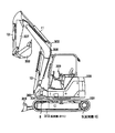
- FIG. 2 shows the external appearance of the hydraulic excavator.
- a hydraulic excavator well known as a work machine includes an upper swing body 300, a lower traveling body 301, and a swing type front work machine 302.
- the front work machine 302 includes a boom 306, an arm 307, The bucket 308 is configured.
- the upper swing body 300 can swing the lower traveling body 301 by the rotation of the swing motor 7.
- a swing post 303 is attached to the front portion of the upper swing body 300, and a front work machine 302 is attached to the swing post 303 so as to be movable up and down.
- the swing post 303 can be rotated in the horizontal direction with respect to the upper swing body 300 by expansion and contraction of the swing cylinder 9 (see FIG. 1).
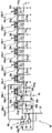
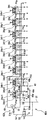
- FIG. 1A shows a hydraulic drive device for a hydraulic excavator according to the first embodiment of the present invention.
- the hydraulic drive apparatus includes an engine 1, a main hydraulic pump (hereinafter referred to as a main pump) 2 driven by the engine 1, and a pilot pump 3 driven by the engine 1 in conjunction with the main pump 2.
- a main pump 2 driven by the engine 1
- a pilot pump 3 driven by the engine 1 in conjunction with the main pump 2.
- Left and right traveling motors 5, 6, turning motor 7, blade cylinder 8, which are a plurality of actuators 5, 6, 7, 8, 9, 10, 11, 12 driven by the pressure oil discharged from main pump 2.
- a swing cylinder 9, a boom cylinder 10, an arm cylinder 11, a bucket cylinder 12, and a control valve 4 are provided.
- the hydraulic excavator according to the present embodiment is, for example, a hydraulic mini excavator.
- the control valve 4 is connected to the supply oil passage 2a of the main pump 2, and has a plurality of valve sections 13, 14, 15, 16, 17 for controlling the direction and flow rate of the pressure oil supplied from the main pump 2 to each actuator. , 18, 19, 20 and a plurality of actuators 5, 6, 7, 8, 9, 10, 11, 12 to select the highest load pressure (hereinafter referred to as the maximum load pressure) PLmax and signal oil
- a plurality of shuttle valves 22 a, 22 b, 22 c, 22 d, 22 e, 22 f, and 22 g that are output to the passage 21 are connected to the supply oil passage 4 a that is connected to the supply oil passage 2 a of the main pump 2.
- a main relief valve 23 that limits the maximum discharge pressure (maximum pump pressure) and a pilot hydraulic pressure source 33 (described later), and signals the pressure in the supply oil passage 4a and the signal oil passage 21.
- the pressure is input as a pressure, and is connected to a differential pressure reducing valve 24 that outputs a differential pressure PLS between the discharge pressure (pump pressure) Pd of the main pump 2 and the maximum load pressure PLmax as an absolute pressure, and a supply oil passage 4a in the valve to supply
- the pressure of the oil passage 4a and the signal oil passage 21 is input as a signal pressure, and when the differential pressure PLS between the pump pressure Pd and the maximum load pressure PLmax exceeds a certain value set by the spring 25a, the discharge of the main pump 2
- An unload valve 25 is provided that returns a part of the flow rate to the tank T and keeps the differential pressure PLS below a predetermined value set by the spring 25a.
- the outlet sides of the unload valve 25 and the main relief valve 23 are connected to a tank
- the valve section 13 includes a flow control valve 26a and a pressure compensation valve 27a
- the valve section 14 includes a flow control valve 26b and a pressure compensation valve 27b
- the valve section 15 includes a flow control valve 26c and a pressure compensation valve 27c
- the valve section 16 is composed of a flow control valve 26d and a pressure compensation valve 27d
- the valve section 17 is composed of a flow control valve 26e and a pressure compensation valve 27e
- the valve section 18 is composed of a flow control valve 26f and a pressure
- the valve section 19 includes a flow rate control valve 26g and a pressure compensation valve 27g
- the valve section 20 includes a flow rate control valve 26h and a pressure compensation valve 27h.
- the flow control valves 26a to 26h control the direction and flow rate of the pressure oil supplied from the main pump 2 to the actuators 5 to 12, respectively.
- the pressure compensation valves 27a to 27h are differential pressures before and after the flow control valves 26a to 26h. To control each.
- the pressure compensating valves 27a to 27h have valve-opening side pressure receiving portions 28a, 28b, 28c, 28d, 28e, 28f, 28g, and 28h for setting a target differential pressure.
- the pressure receiving portions 28a to 28h include a differential pressure reducing valve 24.
- the target compensation differential pressure is set by the absolute pressure of the differential pressure PLS between the hydraulic pump pressure Pd and the maximum load pressure PLmax (hereinafter referred to as the absolute pressure PLS).
- the absolute pressure PLS the absolute pressure of the differential pressure PLS between the hydraulic pump pressure Pd and the maximum load pressure PLmax
- Control is performed so as to be equal to the differential pressure PLS from the load pressure PLmax.
- the discharge flow rate of the main pump 2 is distributed according to the opening area ratio of the flow rate control valves 26a to 26h regardless of the load pressure of the actuators 5 to 12. Combined operability can be ensured.
- the differential pressure PLS decreases according to the degree of supply shortage, and the pressure compensation valves 27a to 27h control accordingly.
- the discharge flow rate of the main pump 2 can be distributed to ensure composite operability.
- the pressure compensation valves 27a to 27h are pressure compensation valves that do not fully close at the stroke end in the direction of decreasing the opening area (the left direction in the figure).
- the hydraulic drive device is connected to the supply oil passage 3 a of the pilot pump 3, and outputs the absolute pressure according to the discharge flow rate of the pilot pump 3, and the downstream side of the engine speed detection valve 30.
- a pilot hydraulic pressure source 33 having a pilot relief valve 32 that keeps the pressure of the pilot oil passage 31 constant, and a flow rate that is connected to the pilot oil passage 31 and uses the pressure of the pilot hydraulic pressure source 32 as an original pressure (pilot primary pressure).
- Operating pilot pressures (pilot secondary pressures) a, b, c, d, e, f, g, h, i, j, k, l, m, n, o, p for operating the control valves 26a to 26h
- Operating device 34a provided with remote control valves 34a-2, 34b-2, 34c-2, 34d-2, 34e-2, 34f-2, 34g-2, 34h-2 (see FIG. 1B) 34b, and includes 34c, 34d, 34e, 34f, 34g, and 34h.
- the engine speed detection valve 30 includes a throttle element (fixed throttle part) 30f provided in an oil path connecting the supply oil path 3a of the pilot pump 3 to the pilot oil path 31, and a flow rate connected in parallel to the throttle element 30f. It has a detection valve 30a and a differential pressure reducing valve 30b.
- the input side of the flow rate detection valve 30 a is connected to the supply oil passage 3 a of the pilot pump 3, and the output side of the flow rate detection valve 30 a is connected to the pilot oil passage 31.
- the flow rate detection valve 30a has a variable throttle portion 30c that increases the opening area as the passing flow rate increases, and the discharge oil of the pilot pump 3 passes through both the throttle element 30f and the variable throttle portion 30c of the flow rate detection valve 30a.
- a differential pressure increases and decreases as the passing flow rate increases in the throttle element 30f and the variable throttle portion 30c of the flow rate detection valve 30a, and the differential pressure reducing valve 30b outputs the differential pressure as the absolute pressure Pa.
- the discharge flow rate of the pilot pump 3 varies depending on the rotation speed of the engine 1
- the discharge flow rate of the pilot pump 3 can be detected by detecting the differential pressure across the throttle element 30f and the variable throttle portion 30c. The number of rotations can be detected.
- the variable throttle portion 30c increases the opening area as the passing flow rate increases (as the front-rear differential pressure increases), so that the degree of increase in the front-rear differential pressure becomes milder as the passing flow rate increases. It is configured as follows.
- the main pump 2 is a variable displacement hydraulic pump, and includes a pump control device 35 for controlling the tilt angle (capacity) thereof.
- the pump control device 35 includes a pump torque control unit 35A and an LS control unit 35B.
- the pump torque control unit 35A includes a torque control tilt actuator 35a, and the torque control tilt actuator 35a is configured so that the tilt angle (capacity) of the main pump 2 decreases as the discharge pressure of the main pump 2 increases.
- the swash plate (capacity variable member) 2s is driven, and the input torque of the main pump 2 is limited so as not to exceed the preset maximum torque. Thereby, the horsepower consumption of the main pump 2 is limited, and the stop (engine stall) of the engine 1 due to overload is prevented.
- the LS control unit 35B includes an LS control valve 35b and an LS control tilt actuator 35c.
- the LS control valve 35b has pressure receiving portions 35d and 35e facing each other, and the pressure receiving portion 35d receives the absolute pressure Pa generated by the differential pressure reducing valve 30b of the engine speed detection valve 30 via the oil passage 40.
- the absolute pressure PLS (the differential pressure PLS between the discharge pressure Pd of the main pump 2 and the maximum load pressure PLmax) generated by the differential pressure reducing valve 24 in the pressure receiving portion 35e is guided as a target differential pressure (target LS differential pressure). Guided as feedback differential pressure.
- the absolute pressure PLS becomes higher than the absolute pressure Pa (PLS> Pa)
- the LS control valve 35b guides the pressure of the pilot hydraulic source 33 to the LS control tilt actuator 35c, and the absolute pressure PLS becomes lower than the absolute pressure Pa.
- the LS control tilt actuator 35c is communicated with the tank T.
- the LS control tilt actuator 35c drives the swash plate 2s of the main pump 2 so that the tilt angle of the main pump 2 decreases when the pressure of the pilot hydraulic power source 33 is guided.
- the swash plate 2s of the main pump 2 is driven so as to increase the tilt angle.
- the tilt angle (capacity) of the main pump 2 is controlled so that the discharge pressure Pd of the main pump 2 becomes higher than the maximum load pressure PLmax by the absolute pressure Pa (target differential pressure).
- the absolute pressure Pa is a value that changes according to the engine speed
- the absolute pressure Pa is used as the target differential pressure of the load sensing control
- the target compensated differential pressure of the pressure compensating valves 27a to 27h is used for the main pump 2.
- the set pressure of the spring 25a of the unload valve 25 is the absolute pressure Pa (target differential pressure for load sensing control) generated by the differential pressure reducing valve 30b of the engine speed detecting valve 30 when the engine 1 is at the rated maximum speed. ) Is set to be slightly higher.
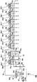
- FIG. 1B is an enlarged view of the operation devices 34a, 34b, 34c, 34d, 34e, 34f, 34g, and 34h and their pilot circuit portions.
- the operating device 34a has an operating lever 34a-1 and a remote control valve 34a-2, and the remote control valve 34a-2 includes a pair of pressure reducing valves PVa and PVb.
- the pressure reducing valve PVa of the remote control valve 34a-2 is activated to generate an operation pilot pressure a having a magnitude corresponding to the operation amount of the operation lever 34a-1
- the operation lever 34a When -1 is operated in the left direction in the figure, the pressure reducing valve PVb of the remote control valve 34a-2 is activated to generate an operating pilot pressure b having a magnitude corresponding to the operating amount of the operating lever 34a-1.
- the operation devices 34b to 34h are configured similarly. That is, the operating devices 34b to 34h are respectively provided with operating levers 34b-1, 34c-1, 34d-1, 34e-1, 34f-1, 34g-1, 34h-1, and remote control valves 34b-2, 34c-2.
- the operating pilot pressures d, f, h, j, l having magnitudes corresponding to the operating amounts of the levers 34b-1, 34c-1, 34d-1, 34e-1, 34f-1, 34g-1, 34h-1 n and p are generated.
- the hydraulic drive device has, as a characteristic configuration, a remote control valve 34b-2, 34c-2, 34d-2, 34e of the operation devices 34a, 34b, 34c, 34d, 34e, 34f, 34g, 34h.
- a pilot primary pressure circuit 40 that supplies a pilot primary pressure that is the pressure of the pilot hydraulic pressure source 33
- the pilot primary pressure circuit 40 includes a traveling operation device 34 a. 34b, remote control valves 34a-2 and 34b-2, a first circuit 41 for supplying pilot primary pressure, and operation devices other than the travel operation device (hereinafter simply referred to as operation devices other than travel) 34c to 34h.
- a second circuit 42 for supplying pilot primary pressure to 2 to 34h-2.
- the second circuit 42 supplies the pilot primary pressure as it is to the remote control valves 34c-2 to 34h-2 of the operation devices 34c to 34h other than the travel.
- the pilot primary pressure is reduced and supplied to the remote control valves 34c-2 to 34h-2 of the operating devices 34c to 34h other than traveling.
- the travel motors 5 and 6 are specific actuators
- the travel operation devices 34a and 34b are specific operation devices corresponding to specific actuators (travel motors 5 and 6) among the plurality of operation devices 34a to 34h.
- a specific actuator means that the other actuator is on the low load pressure side when the combined operation of simultaneously driving the specific actuator and the other actuator is performed, and the load pressure of the specific actuator is other than This is an actuator that becomes so high that the pressure compensation valve of the actuator (actuator on the low load side) operates to near the stroke end.
- the hydraulic drive apparatus further includes an operation detection device 43 that detects the operation of the travel operation devices 34a and 34b.
- the operation detection device 43 is a remote control valve for the travel operation devices 34a and 34b.
- Shuttle valves 48a, 48b, and 48c that detect the operation pilot pressure (traveling operation pilot pressure) generated by 34a-2 and 34b-2 and output them as hydraulic signals are provided.
- the second circuit 42 travels by switching the pressure of the third circuit 44 and the pressure of the fourth circuit 45, the third circuit 44 that guides the pilot primary pressure as it is, the fourth circuit 45 that guides the pilot primary pressure by reducing it.
- the fourth circuit 45 has a pressure reducing valve 47 that reduces the pilot primary pressure, and the switching valve 46 is a shuttle valve.
- the pilot pressure receiving portion 46a through which oil pressure signals from 48a, 48b and 48c are guided through an oil passage 48d.
- the switching valve 46 When the operation levers 34a-1 and 34b-1 of the travel operation devices 34a and 34b are not operated and the travel operation pilot pressure is not generated, the switching valve 46 is in the first position on the right side of the figure, The third circuit 44 communicates with a circuit 49 that leads to the remote control valves 34c-2 to 34h-2 of the operating devices 34c to 34h other than traveling, and the pilot primary pressure remains as it is as the remote control valve 34c-2 of the operating devices 34c to 34h other than traveling. To 34h-2. When the operation levers 34a-1 and 34b-1 of the travel operation devices 34a and 34b are operated to generate a travel operation pilot pressure, the travel operation pilot pressure is guided to the pilot pressure receiving portion 46a of the switching valve 46.
- the switching valve 46 is switched to the second position on the left side of the figure, and the fourth circuit 45 communicates with the circuit 49 leading to the remote control valves 34c-2 to 34h-2 of the operating devices 34c to 34h other than traveling, and the pilot primary pressure is The pressure is reduced by the pressure reducing valve 47 and guided to the remote control valves 34c-2 to 34h-2 of the operating devices 34c to 34h other than traveling.
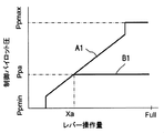
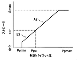
- 3A to 3C are diagrams showing changes in the opening areas of the flow control valves 26c to 26h with respect to the lever operation amounts of the operation devices 34c to 34h at that time.
- the traveling operation pilot pressure is not generated, and therefore the switching valve 46 is in the first position on the right side of the drawing, and the pilot hydraulic pressure
- the pilot primary pressure of the source 33 is introduced as it is to the remote control valves 34c-2 to 34h-2 of the operating devices 34c to 34h other than traveling.
- the operation pilot pressure generated by the remote control valves 34c-2 to 34h-2 and the flow control valves 26c to 26c other than traveling are controlled.
- the spool stroke and opening area of 26h change as indicated by a characteristic A1 in FIG.
- the operation pilot pressure increases.
- the lever operation amount increases to the intermediate operation amount Xa and the operation pilot pressure increases to Ppa, the lever operation amount can be further increased.
- the operating pilot pressure does not increase any more, and the operating pilot pressure is constant at Ppa (characteristic B1 in FIG. 3A).
- the operating pilot pressure Ppa is a pressure equal to the pressure reduced by the pilot primary pressure (pressure reduced by the pressure reducing valve 47).
- the spool stroke of the flow control valves 26c to 26h other than traveling increases only from zero to the intermediate stroke Str corresponding to the operating pilot pressure Ppa, and the maximum stroke of the flow control valves 26c to 26h other than traveling is the intermediate stroke Str. (Characteristic B2 in FIG. 3B), and the maximum opening area of the meter-in is also limited to an intermediate opening area Astr corresponding to the intermediate stroke Str (characteristic B3 in FIG. 3C).
- the travel levers 34a-1 and 34b-1 of the travel operation devices 34a and 34b are operated, the operation levers 34c-1 to 34h-1 of the operation devices 34c to 34h other than the travel are operated. Even if the operation is performed, the meter-in opening area of the flow control valves 26c to 26h other than traveling is restricted, and the required flow rates of the flow control valves 26c to 26h are limited.
- the oil discharged from the main pump 2 is supplied to the supply oil passages 2a and 4a, and the pressure in the supply oil passages 2a and 4a increases.
- the supply oil passage 4a is provided with an unload valve 25.
- the pressure in the supply oil passage 2a becomes higher than the maximum load pressure PLmax (in this case, the tank pressure) by more than the set pressure of the spring 25a.
- the pressure oil in the supply oil passage 2a is returned to the tank in an open state, and the increase in the pressure in the supply oil passage 2a is restricted. Thereby, the discharge pressure of the main pump 2 is controlled to the minimum pressure Pmin.
- the differential pressure reducing valve 24 outputs a differential pressure PLS between the discharge pressure Pd of the main pump 2 and the maximum load pressure PLmax (in this case, tank pressure) as an absolute pressure.
- the output pressure of the engine speed detection valve 30 and the output pressure of the differential pressure reducing valve 24 are guided to the LS control valve 35b of the LS control unit 35B of the main pump 2, and the discharge pressure of the main pump 2 increases.
- the LS control valve 35b is switched to the right position in the figure, and the pressure of the pilot hydraulic power source 33 is applied to the LS control tilt actuator 35c. It is guided and controlled so that the tilt angle of the main pump 2 becomes small.
- the main pump 2 is provided with a stopper (not shown) that defines the minimum tilt angle, the main pump 2 is held at the minimum tilt angle qmin defined by the stopper, and the minimum flow rate is maintained. Qmin is discharged.
- the flow rate flowing through the flow control valve 26f is determined by the opening area of the meter-in throttle of the flow control valve 26f and the differential pressure across the meter-in throttle, and the differential pressure across the meter-in throttle is determined by the pressure compensation valve 27f and the output pressure of the differential pressure reducing valve 24. Since they are controlled to be equal to each other, the flow rate flowing through the flow rate control valve 26f (and hence the drive speed of the boom cylinder 10) is controlled according to the operation amount of the operation lever.
- the load pressure of the boom cylinder 10 is detected as the maximum load pressure by the shuttle valves 22a to 22g and transmitted to the differential pressure reducing valve 24 and the unload valve 25.
- the cracking pressure of the unload valve 25 (pressure at which the unload valve 25 starts to open) rises accordingly, and the pressure of the supply oil passage 2a Is transiently higher than the set pressure of the spring 25a above the maximum load pressure, the unload valve 25 opens to return the pressure oil in the supply oil passage 4a to the tank.
- the pressure in the supply oil passages 2a and 4a is restricted from rising above the set pressure of the spring 25a from the maximum load pressure PLmax.
- the output pressure of the engine speed detection valve 30 and the output pressure of the differential pressure reducing valve 24 are guided to the LS control valve 35b of the LS control unit 35B of the main pump 2, and the output pressure of the differential pressure reducing valve 24 is
- the LS control valve 35b switches to the left position in the figure, and the LS control tilt actuator 35c is communicated with the tank T so that the LS control tilt actuator 35c pressure oil is supplied to the tank.
- the tilt angle of the main pump 2 is controlled to increase, and the discharge flow rate of the main pump 2 increases.
- the increase in the discharge flow rate of the main pump 2 continues until the output pressure of the differential pressure reducing valve 24 becomes equal to the output pressure of the engine speed detection valve 30.
- the discharge pressure of the main pump 2 (pressure in the supply oil passages 2a and 4a) is controlled to be higher than the maximum load pressure PLmax by the output pressure (target differential pressure) of the engine speed detection valve 30.
- So-called load sensing control is performed in which the flow rate required by the boom flow control valve 26f is supplied to the boom cylinder 10.
- the flow control valves 26f and 26g are switched.
- the pressure oil is supplied to the boom cylinder 10 and the arm cylinder 11, and the boom cylinder 10 and the arm cylinder 11 are driven.
- the higher pressure of the load pressures of the boom cylinder 10 and the arm cylinder 11 is detected as the maximum load pressure PLmax by the shuttle valves 22a to 22g and transmitted to the differential pressure reducing valve 24 and the unloading valve 25.
- the operation when the maximum load pressure PLmax detected by the shuttle valves 22a to 22g is guided to the unload valve 25 is the same as when the boom cylinder 10 is driven alone, and according to the increase in the maximum load pressure PLmax.
- the cracking pressure of the unload valve 25 increases, and the pressure in the supply oil passages 2a, 4a is restricted from rising above the set pressure of the spring 25a from the maximum load pressure PLmax.
- the output pressure of the engine speed detection valve 30 and the output pressure of the differential pressure reducing valve 24 are guided to the LS control valve 35b of the LS control unit 35B of the main pump 2, and the boom cylinder 10 is driven independently.
- the discharge pressure of the main pump 2 pressure in the supply oil passages 2a and 4a
- the output pressure (target differential pressure) of the engine speed detection valve 30 So-called load sensing control is performed in which the flow rate required by the flow rate control valves 26f and 26g is supplied to the boom cylinder 10 and the arm cylinder 11.
- the output pressure of the differential pressure reducing valve 24 is guided to the pressure compensating valves 27a to 27h as the target compensating differential pressure, and the pressure compensating valves 27f and 27g use the differential pressure before and after the flow control valves 26f and 26g to the main pump 2. Control is made to be equal to the differential pressure between the discharge pressure and the maximum load pressure PLmax. As a result, pressure oil is supplied to the boom cylinder 10 and the arm cylinder 11 at a ratio corresponding to the opening area of the meter-in throttle portions of the flow control valves 26f and 26g regardless of the load pressure of the boom cylinder 10 and the arm cylinder 11. Can do.
- the pressure compensation valves 27a to 27h are configured not to be fully closed at the stroke end in the direction of decreasing the opening area (left direction in the drawing), the other is operated during the operation of one of the boom cylinder 10 and the arm cylinder 11. Even if saturation occurs due to the combined operation, and the pressure compensation valve on the low load side moves greatly in the direction of decreasing the opening area, the pressure compensation valve on the low load pressure side is prevented from closing and the pressure oil is completely shut off Therefore, it is possible to prevent the actuator on the low load pressure side from being decelerated and stopped.
- the flow control valve 26g is switched and the arm cylinder 11 is switched. Also, pressure oil is supplied to drive the arm cylinder 11.
- the operating levers 34a-1 and 34b-1 of the operating devices 34a and 34b for traveling are operated to generate operating pilot pressure for traveling, and the switching valve 46 is switched to the second position on the left side of the drawing, thereby Since the pilot primary pressure 33 is reduced and guided to the remote control valve 34g-2 of the arm operating device 34g, the arm operating device 34g is used as described with reference to FIGS. 3A, 3B, and 3C.
- the operation pilot pressure generated by the remote control valve 34g-2 is limited to Ppa in FIG. 3A
- the spool stroke of the flow control valve 26g is limited to Str in FIG. 3B
- the meter-in opening area is the intermediate opening area Astr in FIG. 3C.
- the pressure compensation valve is a type of pressure compensation valve that does not fully close at the stroke end in the direction of decreasing the opening area
- another driven member for example, boom, arm, bucket
- the pressure compensation valve of low-load actuators such as boom cylinders, arm cylinders, and bucket cylinders, which have a lower load pressure than the traveling motor, will open even when the stroke end is reached. Therefore, all the discharge flow rate of the hydraulic pump flows through the low-load actuator, and traveling may be decelerated and stopped.
- the meter-in opening area of the flow control valve 26g is limited to Astr, and the required flow rate is limited. Therefore, the flow rate flowing through the low load pressure actuator is reduced. As a result, the required amount of pressure oil to the traveling motors 5 and 6 is ensured, the traveling is prevented from being decelerated and stopped, and good combined operability can be obtained.
- the pressure compensation valve is a type of pressure compensation valve that does not fully close at the stroke end in the opening area decreasing direction. Since the pressure oil flows through the blade cylinder 8, the running is decelerated and stopped, creating a shock sensibly and impairing the operation feeling.
- the request for the flow control valve 26d for the blade is the same as when the operation lever of any one of the operation devices of the boom, arm, and bucket is operated in order to change the posture of the front work machine during traveling. Since the flow rate is limited, a necessary amount of pressure oil to the traveling motors 5 and 6 is ensured, the traveling is prevented from being decelerated and stopped, and the operational feeling can be improved.
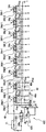
- FIG. 4 shows an operating device and a pilot circuit portion thereof in a hydraulic drive device of a hydraulic excavator according to the second embodiment of the present invention.
- the same components as those shown in FIG. 1B are denoted by the same reference numerals, and description thereof is omitted.
- This embodiment is different from the first embodiment in the configuration for reducing the pilot primary pressure and the configuration for switching the pilot primary pressure.
- the hydraulic drive apparatus in the present embodiment includes a pilot primary pressure circuit 40A
- the second circuit 42A of the pilot primary pressure circuit 40A includes a fifth circuit 52 including a pilot operated pressure reducing valve 51, and a pilot operated pressure reducing pressure.
- a sixth circuit 54 having a switching valve 53 for switching the pilot pressure guided to the pilot pressure receiving portion 51a of the valve 51 between the pressure of the pilot hydraulic power source 33 (first pressure) and the tank pressure (second pressure);
- the fifth circuit 52 uses the pilot primary pressure as it is for the remote control valve 34c of the operating devices 34c to 34h other than traveling.
- the pilot pressure led to the pilot pressure receiving part 51a of the pilot operated pressure reducing valve 51 is When switched to tank pressure has a configuration which guides the pilot primary pressure to the remote control valve operation device other than traveling in vacuo.
- the pressure of the pilot hydraulic power source 33 passes through the switching valve 53. Therefore, the pressure on the outlet side of the pilot operated pressure reducing valve 51 is not reduced, and the pressure of the pilot hydraulic power source 33 (pilot primary pressure) is applied to the operating devices 34c to 34h other than traveling.
- the remote control valves 34c-2 to 34h-2 are supplied.
- the spool stroke (meter-in opening area) of the flow control valves 26c to 26h is not limited, and an operation such as a normal excavation operation can be performed.
- the operating levers 34a-1 and 34b-1 of the operating devices 34a and 34b for traveling are operated, the operating pilot pressure for traveling is guided to the pilot pressure receiving portion 53a of the switching valve 53, and the switching valve 53 is switched.
- the pressure oil guided to the pilot pressure receiving portion 51a of the pilot operated pressure reducing valve 51 is shut off.
- the primary pilot pressure guided to the remote control valves 34c to 34h of the operating device other than the traveling is reduced by the pilot actuated pressure reducing valve 51, and the spool stroke (meter-in opening area) of the flow control valves 26c to 26h is limited. Since the flow rate is limited, a necessary amount of pressure oil to the traveling motors 5 and 6 is ensured, the traveling is prevented from stopping, and good combined operability can be obtained.
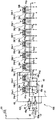
- FIG. 5 shows an operating device and a pilot circuit portion thereof in a hydraulic drive device of a hydraulic excavator according to a third embodiment of the present invention.
- the same components as those shown in FIG. 1B are denoted by the same reference numerals, and description thereof is omitted.
- This embodiment is different from the first embodiment in the configuration (fourth circuit) for reducing the pilot primary pressure.
- the hydraulic drive apparatus in the present embodiment includes a pilot primary pressure circuit 40B, and the second circuit 42B of the pilot primary pressure circuit 40B reduces the pilot primary pressure by the third circuit 61 that guides the pilot primary pressure as it is.
- a fourth circuit 62 for guiding, and a switching valve 63 for switching the pressure of the third circuit 61 and the pressure of the fourth circuit 62 to the remote control valve of the operating device other than traveling are provided, and the fourth circuit 62 generates the pilot primary pressure.
- An aperture circuit 64 for reducing the pressure is provided.
- the throttle circuit 64 has an upstream side connected to the pilot oil passage 31 and a downstream side connected to the tank T via the low pressure relief valve 64a, and two fixed throttles 64c and 64d provided in the oil passage 64b. And an oil passage 64e connected between the two fixed throttles 64c and 64d, and an intermediate pressure reduced by the two fixed throttles 64c and 64d is guided to the oil passage 64e.
- the pressure of the pilot hydraulic power source 33 (pilot primary pressure) is maintained at a normal pressure set by the pilot relief valve 32 (see FIG. 1A) by the fixed throttle 64c, and the operating levers 34a- of the operating devices 34a, 34b for traveling are maintained. 1, 34 b-1 is not operated, the pressure of the pilot hydraulic power source 33 (pilot primary pressure) is applied to the remote control valves 34 c-2 to 34 h-2 of the operating devices 34 c to 34 h other than traveling via the switching valve 63. Accordingly, the spool stroke (meter-in opening area) of the flow control valves 26c to 26h is not limited, and an ordinary excavation operation or the like can be performed.
- the travel operation pilot pressure is guided to the pilot pressure receiving portion 63a of the switching valve 63, and the switching valve 63 is switched.
- the pressure reduced by the fixed throttles 64c and 64d of the throttle circuit 64 is guided to the remote control valves 34c to 34h of the operating device other than the traveling.
- the spool stroke (meter-in opening area) of the flow control valves 26c to 26h is limited and the required flow rate is limited, so that a necessary amount of pressure oil is secured to the travel motors 5 and 6 and travel stops. Can be prevented, and good composite operability can be obtained.
- FIG. 6 shows an operating device and a pilot circuit portion thereof in a hydraulic drive device of a hydraulic excavator according to the fourth embodiment of the present invention.
- the same components as those shown in FIG. 1B are denoted by the same reference numerals, and description thereof is omitted.
- This embodiment is different from the first embodiment in the configuration for switching between the third circuit and the fourth circuit.
- the hydraulic drive apparatus in the present embodiment includes a pilot primary pressure circuit 40C, and the second circuit 42C of the pilot primary pressure circuit 40C is an electromagnetic switching valve instead of the hydraulic switching valve 46 in the first embodiment.
- the operation detection device 43C has a pressure sensor 72 that detects an operation pilot pressure generated by a remote control valve of the traveling operation device among a plurality of operation devices and outputs an electric signal.
- the electrical signal of the pressure sensor 72 is input to the controller 71, and the controller 71 converts the electrical signal into a drive signal for the electromagnetic switching valve 46C and outputs it to the solenoid 46b of the electromagnetic switching valve 46C.
- the electromagnetic switching valve 46C When the operating levers 34a-1 and 34b-1 of the travel operating devices (specific operating devices) 34a and 34b are not operated and no drive signal is output from the controller 71, the electromagnetic switching valve 46C is in the first position on the right side of the figure.
- the third circuit 44 communicates with a circuit 49 leading to the remote control valves 34c-2 to 34h-2 of the operation devices 34c to 34h other than traveling, and the pilot primary pressure remains as it is for the remote control valves of the operation devices 34c to 34h other than traveling. 34c-2 to 34h-2.
- the electromagnetic switching valve 46C When the operation levers 34a-1 and 34b-1 of the travel operation devices 34a and 34b are operated and a drive signal is output from the controller 71, the electromagnetic switching valve 46C is activated and switched to the second position on the left side in the figure.
- the fourth circuit 45 communicates with a circuit 49 leading to the remote control valves 34c-2 to 34h-2 of the operation devices 34c to 34h other than traveling, and the pilot primary pressure is reduced by the pressure reducing valve 47 so that the operation devices 34c to 34c other than traveling are operated. Guided to the remote control valves 34c-2 to 34h-2 of 34h.
- the switching valve 46 in FIG. 1B is an electromagnetic switching valve.
- the switching valve 53 in FIG. 4 and the switching valve 63 in FIG. It is also possible to provide a pressure sensor and a controller, and to switch the electromagnetic switching valve by an electric signal from the controller.
- FIG. 7 shows an operating device and a pilot circuit portion thereof in a hydraulic drive device of a hydraulic excavator according to a fifth embodiment of the present invention.
- the same components as those shown in FIG. 1B are denoted by the same reference numerals, and description thereof is omitted.
- This embodiment is different from the first embodiment in the configuration for switching the switching valve of the second circuit.
- the hydraulic drive device further includes a manual selection device 81 that can be switched between the first position and the second position.
- the manual selection device 81 is, for example, a switch that outputs an electrical signal corresponding to the switching position.
- the second circuit 42D of the pilot primary pressure circuit 40D is disposed in the oil passage 48d that guides the hydraulic signal detected by the operation detection device 43 to the pilot pressure receiving portion 46a of the switching valve 46, and is a manual selection device.
- (Manual switch) 81 is further provided with an electromagnetic switching valve 83 that operates based on an electric signal from 81.
- the electromagnetic switching valve 83 When the manual selection device 81 is in the first position and no electrical signal is output, the electromagnetic switching valve 83 is in the first position on the right side of the figure, and the hydraulic signal detected by the operation detection device 43 is guided to the switching valve 46.
- the manual selection device 81 When the manual selection device 81 is switched to the second position and an electric signal is output to the solenoid 83a of the electromagnetic switching valve 83, it switches to the second position on the left side of the figure and is detected by the operation detection device 43. The hydraulic signal is not guided to the switching valve 46.
- the pilot primary pressure when the operation levers 34a-1 and 34b-1 of the travel operation devices (specific operation devices) 34a and 34b are operated is reduced.
- the function is effective, and the operation pilot pressure for the actuators other than the traveling is reduced during the traveling combined operation, and the control for limiting the required flow rate can be performed.
- the manual selection device 81 is switched to the second position, the pilot primary pressure when the operation levers 34a-1 and 34b-1 of the travel operation devices (specific operation devices) 34a and 34b are operated is reduced.
- the function becomes invalid, and the operation pilot pressure for the actuators other than the traveling is not reduced even during the traveling combined operation, the maximum stroke of the flow control valves 26c to 26h is not limited, and the conventional operation is possible.
- a spare actuator provided in an attachment such as a crusher often has a high load pressure.
- other actuators for example, a boom, an arm, a bucket, etc.
- the required flow rate to other actuators can be limited during the combined operation, and pressure oil can be preferentially supplied to the spare actuator.
- the present invention is applied to a construction machine other than the hydraulic excavator (for example, a hydraulic crane, a wheeled excavator, etc.) to obtain the same effect. Can do.
Landscapes
- Engineering & Computer Science (AREA)
- General Engineering & Computer Science (AREA)
- Mining & Mineral Resources (AREA)
- Civil Engineering (AREA)
- Structural Engineering (AREA)
- Physics & Mathematics (AREA)
- Fluid Mechanics (AREA)
- Mechanical Engineering (AREA)
- Operation Control Of Excavators (AREA)
- Fluid-Pressure Circuits (AREA)
Priority Applications (4)
| Application Number | Priority Date | Filing Date | Title |
|---|---|---|---|
| EP13775007.1A EP2837831B1 (en) | 2012-04-10 | 2013-04-01 | Hydraulic drive device of construction machine |
| US14/383,150 US20150027112A1 (en) | 2012-04-10 | 2013-04-01 | Hydraulic drive system for construction machine |
| CN201380018871.XA CN104246237B (zh) | 2012-04-10 | 2013-04-01 | 工程机械的液压驱动装置 |
| US15/883,357 US10655647B2 (en) | 2012-04-10 | 2018-01-30 | Hydraulic drive system for construction machine |
Applications Claiming Priority (2)
| Application Number | Priority Date | Filing Date | Title |
|---|---|---|---|
| JP2012-089670 | 2012-04-10 | ||
| JP2012089670A JP5878811B2 (ja) | 2012-04-10 | 2012-04-10 | 建設機械の油圧駆動装置 |
Related Child Applications (2)
| Application Number | Title | Priority Date | Filing Date |
|---|---|---|---|
| US14/383,150 A-371-Of-International US20150027112A1 (en) | 2012-04-10 | 2013-04-01 | Hydraulic drive system for construction machine |
| US15/883,357 Continuation US10655647B2 (en) | 2012-04-10 | 2018-01-30 | Hydraulic drive system for construction machine |
Publications (1)
| Publication Number | Publication Date |
|---|---|
| WO2013153984A1 true WO2013153984A1 (ja) | 2013-10-17 |
Family
ID=49327552
Family Applications (1)
| Application Number | Title | Priority Date | Filing Date |
|---|---|---|---|
| PCT/JP2013/059946 WO2013153984A1 (ja) | 2012-04-10 | 2013-04-01 | 建設機械の油圧駆動装置 |
Country Status (5)
| Country | Link |
|---|---|
| US (2) | US20150027112A1 (zh) |
| EP (1) | EP2837831B1 (zh) |
| JP (1) | JP5878811B2 (zh) |
| CN (1) | CN104246237B (zh) |
| WO (1) | WO2013153984A1 (zh) |
Cited By (2)
| Publication number | Priority date | Publication date | Assignee | Title |
|---|---|---|---|---|
| CN103759930A (zh) * | 2014-01-03 | 2014-04-30 | 武汉船用机械有限责任公司 | 一种平衡阀瞬态试验装置及瞬态试验方法 |
| WO2019188061A1 (ja) * | 2018-03-27 | 2019-10-03 | ヤンマー株式会社 | 作業車両の油圧回路 |
Families Citing this family (14)
| Publication number | Priority date | Publication date | Assignee | Title |
|---|---|---|---|---|
| CN104838073B (zh) * | 2012-11-23 | 2017-03-08 | 沃尔沃建造设备有限公司 | 用于控制工程机械的优先功能的设备和方法 |
| FR3007154B1 (fr) * | 2013-06-12 | 2015-06-05 | Montabert Roger | Procede de commande de l’energie d’impact d’un piston de frappe d’un appareil a percussions |
| JP6082690B2 (ja) * | 2013-12-06 | 2017-02-15 | 日立建機株式会社 | 建設機械の油圧駆動装置 |
| KR102389687B1 (ko) * | 2015-01-14 | 2022-04-22 | 현대두산인프라코어 주식회사 | 건설기계의 제어 시스템 |
| JP6523554B2 (ja) * | 2016-03-31 | 2019-06-05 | 日立建機株式会社 | 建設機械の駆動制御装置 |
| CN107524187B (zh) * | 2017-09-15 | 2020-01-07 | 太原理工大学 | 旋转运动制动能量液电混合回收利用系统 |
| KR102484104B1 (ko) * | 2018-01-31 | 2023-01-04 | 현대두산인프라코어(주) | 건설기계의 주행 제어 장치 및 주행 제어 방법 |
| KR102633378B1 (ko) * | 2019-02-13 | 2024-02-02 | 에이치디현대인프라코어 주식회사 | 건설 기계 |
| JP7096425B2 (ja) * | 2019-03-27 | 2022-07-05 | 日立建機株式会社 | 作業機械 |
| CN112177996B (zh) * | 2020-09-18 | 2023-05-05 | 江苏徐工工程机械研究院有限公司 | 一种正流量上下车复合稳定控制系统及方法 |
| US11313388B1 (en) | 2021-01-29 | 2022-04-26 | Cnh Industrial America Llc | System and method for controlling hydraulic fluid flow within a work vehicle |
| US11143211B1 (en) | 2021-01-29 | 2021-10-12 | Cnh Industrial America Llc | System and method for controlling hydraulic fluid flow within a work vehicle |
| US11530524B2 (en) | 2021-01-29 | 2022-12-20 | Cnh Industrial America Llc | System and method for controlling hydraulic fluid flow within a work vehicle |
| US11261582B1 (en) | 2021-01-29 | 2022-03-01 | Cnh Industrial America Llc | System and method for controlling hydraulic fluid flow within a work vehicle using flow control valves |
Citations (6)
| Publication number | Priority date | Publication date | Assignee | Title |
|---|---|---|---|---|
| JPH04370402A (ja) * | 1991-06-18 | 1992-12-22 | Toshiba Mach Co Ltd | 油圧駆動回路 |
| JPH0776861A (ja) | 1993-09-06 | 1995-03-20 | Hitachi Constr Mach Co Ltd | 建設機械の油圧駆動装置 |
| JP2003156006A (ja) * | 2001-11-16 | 2003-05-30 | Shin Caterpillar Mitsubishi Ltd | 流体圧回路および流体圧回路制御方法 |
| JP2007024103A (ja) | 2005-07-13 | 2007-02-01 | Hitachi Constr Mach Co Ltd | 油圧駆動装置 |
| JP2009167618A (ja) * | 2008-01-11 | 2009-07-30 | Caterpillar Japan Ltd | 油圧ショベルの油圧回路 |
| JP2010047983A (ja) * | 2008-08-21 | 2010-03-04 | Sumitomo (Shi) Construction Machinery Co Ltd | 油圧ショベルの油圧回路 |
Family Cites Families (35)
| Publication number | Priority date | Publication date | Assignee | Title |
|---|---|---|---|---|
| IT1157048B (it) * | 1982-06-14 | 1987-02-11 | Fiat Allis Europ | Circuito idraulico per l'alimentazione di fluido in pressione ad una pluralita di camere utilizzatrici provvisto di mezzi selezionatori per l'alimentazione prioritaria di una o piu delle suddette camere utilizzatrici |
| JP2607258B2 (ja) * | 1988-03-30 | 1997-05-07 | 日立建機株式会社 | 作業機の油圧制御回路 |
| JP2991529B2 (ja) * | 1991-05-29 | 1999-12-20 | 東芝機械株式会社 | 油圧作業回路 |
| JP3477687B2 (ja) * | 1993-11-08 | 2003-12-10 | 日立建機株式会社 | 流量制御装置 |
| US5680760A (en) * | 1996-03-28 | 1997-10-28 | Caterpillar Inc. | Hydraulic drive system |
| JPH11336135A (ja) * | 1998-05-22 | 1999-12-07 | Hitachi Constr Mach Co Ltd | 建設機械の油圧制御回路 |
| WO2000032942A1 (fr) * | 1998-12-03 | 2000-06-08 | Hitachi Construction Machinery Co., Ltd. | Unite d'entrainement hydraulique |
| US6408622B1 (en) * | 1998-12-28 | 2002-06-25 | Hitachi Construction Machinery Co., Ltd. | Hydraulic drive device |
| JP3594839B2 (ja) * | 1999-05-24 | 2004-12-02 | 新キャタピラー三菱株式会社 | 作業機械の旋回制御装置 |
| JP2001323902A (ja) * | 2000-05-16 | 2001-11-22 | Hitachi Constr Mach Co Ltd | 油圧駆動装置 |
| JP3810263B2 (ja) * | 2000-06-29 | 2006-08-16 | 新キャタピラー三菱株式会社 | 作業用機械における油圧回路 |
| JP4128482B2 (ja) * | 2002-04-30 | 2008-07-30 | 東芝機械株式会社 | 油圧制御システム |
| JP2006082767A (ja) * | 2004-09-17 | 2006-03-30 | Hitachi Constr Mach Co Ltd | 走行式建設機械の油圧駆動装置 |
| JP2008180287A (ja) * | 2007-01-24 | 2008-08-07 | Kobelco Contstruction Machinery Ltd | 建設機械の油圧制御装置 |
| JP2010101095A (ja) * | 2008-10-24 | 2010-05-06 | Kobelco Contstruction Machinery Ltd | 作業機械の油圧制御装置 |
| JP5135169B2 (ja) * | 2008-10-31 | 2013-01-30 | 日立建機株式会社 | 建設機械の油圧駆動装置 |
| JP5523028B2 (ja) * | 2009-09-04 | 2014-06-18 | 日立建機株式会社 | 油圧作業機械の油圧駆動装置 |
| JP2011106591A (ja) * | 2009-11-18 | 2011-06-02 | Hitachi Constr Mach Co Ltd | 建設機械の油圧駆動装置 |
| JP2011196436A (ja) * | 2010-03-18 | 2011-10-06 | Yanmar Co Ltd | 作業車両の油圧回路 |
| JP5383591B2 (ja) * | 2010-05-24 | 2014-01-08 | 日立建機株式会社 | 建設機械の油圧駆動装置 |
| JP5368414B2 (ja) * | 2010-11-05 | 2013-12-18 | 日立建機株式会社 | 排気ガス浄化装置を備えた建設機械用油圧駆動システム |
| JP5750454B2 (ja) * | 2011-01-06 | 2015-07-22 | 日立建機株式会社 | 履帯式走行装置を備えた作業機の油圧駆動装置 |
| WO2012125320A1 (en) * | 2011-03-17 | 2012-09-20 | Parker Hannifin Corporation | Electro-hydraulic system for controlling multiple functions |
| EP2752586B1 (en) * | 2011-08-31 | 2019-04-17 | Hitachi Construction Machinery Tierra Co., Ltd. | Hydraulic drive device for construction machine |
| EP2765245B1 (en) * | 2011-10-04 | 2017-12-13 | Hitachi Construction Machinery Tierra Co., Ltd. | Hydraulic drive system used in construction machine and provided with exhaust gas purification device |
| US20140227104A1 (en) * | 2011-10-20 | 2014-08-14 | Hitachi Construction Machinery Co., Ltd. | Hydraulic drive system for electrically-operated hydraulic work machine |
| EP2845954A4 (en) * | 2012-05-01 | 2016-04-06 | Hitachi Construction Machinery | HYBRID CONSTRUCTION EQUIPMENT |
| KR101719676B1 (ko) * | 2012-10-17 | 2017-03-24 | 가부시키가이샤 히다치 겡키 티에라 | 건설 기계의 유압 구동 장치 |
| KR102025780B1 (ko) * | 2013-01-25 | 2019-09-26 | 가부시키가이샤 히다치 겡키 티에라 | 건설 기계의 유압 구동 장치 |
| CN104995412B (zh) * | 2013-03-22 | 2017-03-29 | 株式会社日立建机Tierra | 工程机械的液压驱动装置 |
| US10107311B2 (en) * | 2013-05-30 | 2018-10-23 | Hitachi Construction Machinery Tierra Co., Ltd. | Hydraulic drive system for construction machine |
| JP6021226B2 (ja) * | 2013-11-28 | 2016-11-09 | 日立建機株式会社 | 建設機械の油圧駆動装置 |
| JP6021231B2 (ja) * | 2014-02-04 | 2016-11-09 | 日立建機株式会社 | 建設機械の油圧駆動装置 |
| JP6005088B2 (ja) * | 2014-03-17 | 2016-10-12 | 日立建機株式会社 | 建設機械の油圧駆動装置 |
| JP6231949B2 (ja) * | 2014-06-23 | 2017-11-15 | 株式会社日立建機ティエラ | 建設機械の油圧駆動装置 |
-
2012
- 2012-04-10 JP JP2012089670A patent/JP5878811B2/ja active Active
-
2013
- 2013-04-01 US US14/383,150 patent/US20150027112A1/en not_active Abandoned
- 2013-04-01 WO PCT/JP2013/059946 patent/WO2013153984A1/ja active Application Filing
- 2013-04-01 CN CN201380018871.XA patent/CN104246237B/zh active Active
- 2013-04-01 EP EP13775007.1A patent/EP2837831B1/en active Active
-
2018
- 2018-01-30 US US15/883,357 patent/US10655647B2/en active Active
Patent Citations (6)
| Publication number | Priority date | Publication date | Assignee | Title |
|---|---|---|---|---|
| JPH04370402A (ja) * | 1991-06-18 | 1992-12-22 | Toshiba Mach Co Ltd | 油圧駆動回路 |
| JPH0776861A (ja) | 1993-09-06 | 1995-03-20 | Hitachi Constr Mach Co Ltd | 建設機械の油圧駆動装置 |
| JP2003156006A (ja) * | 2001-11-16 | 2003-05-30 | Shin Caterpillar Mitsubishi Ltd | 流体圧回路および流体圧回路制御方法 |
| JP2007024103A (ja) | 2005-07-13 | 2007-02-01 | Hitachi Constr Mach Co Ltd | 油圧駆動装置 |
| JP2009167618A (ja) * | 2008-01-11 | 2009-07-30 | Caterpillar Japan Ltd | 油圧ショベルの油圧回路 |
| JP2010047983A (ja) * | 2008-08-21 | 2010-03-04 | Sumitomo (Shi) Construction Machinery Co Ltd | 油圧ショベルの油圧回路 |
Non-Patent Citations (1)
| Title |
|---|
| See also references of EP2837831A4 |
Cited By (4)
| Publication number | Priority date | Publication date | Assignee | Title |
|---|---|---|---|---|
| CN103759930A (zh) * | 2014-01-03 | 2014-04-30 | 武汉船用机械有限责任公司 | 一种平衡阀瞬态试验装置及瞬态试验方法 |
| CN103759930B (zh) * | 2014-01-03 | 2016-06-29 | 武汉船用机械有限责任公司 | 一种平衡阀瞬态试验装置及瞬态试验方法 |
| WO2019188061A1 (ja) * | 2018-03-27 | 2019-10-03 | ヤンマー株式会社 | 作業車両の油圧回路 |
| JP2019173803A (ja) * | 2018-03-27 | 2019-10-10 | ヤンマー株式会社 | 作業車両の油圧回路 |
Also Published As
| Publication number | Publication date |
|---|---|
| EP2837831B1 (en) | 2017-06-14 |
| US10655647B2 (en) | 2020-05-19 |
| US20180156242A1 (en) | 2018-06-07 |
| CN104246237B (zh) | 2016-08-17 |
| CN104246237A (zh) | 2014-12-24 |
| JP5878811B2 (ja) | 2016-03-08 |
| EP2837831A1 (en) | 2015-02-18 |
| EP2837831A4 (en) | 2015-12-30 |
| JP2013217466A (ja) | 2013-10-24 |
| US20150027112A1 (en) | 2015-01-29 |
Similar Documents
| Publication | Publication Date | Title |
|---|---|---|
| JP5878811B2 (ja) | 建設機械の油圧駆動装置 | |
| JP5984164B2 (ja) | 建設機械の油圧駆動装置 | |
| EP1995155B1 (en) | Traveling device for crawler type heavy equipment | |
| JP5779256B2 (ja) | 建設機械の油圧システム | |
| JP5383591B2 (ja) | 建設機械の油圧駆動装置 | |
| JP5886976B2 (ja) | 作業機械 | |
| WO2010128645A1 (ja) | ハイブリッド建設機械の制御装置 | |
| WO2011004880A1 (ja) | ハイブリッド建設機械 | |
| WO2004083646A1 (ja) | 作業機の油圧回路 | |
| WO2019220954A1 (ja) | 油圧ショベル駆動システム | |
| JP2014029180A (ja) | 作業機械の油圧制御装置 | |
| JP2012162917A (ja) | 油圧ショベルの油圧回路 | |
| JP7207060B2 (ja) | 作業機械の油圧駆動装置 | |
| WO2019053933A1 (ja) | 建設機械の駆動装置 | |
| JP2012112466A (ja) | 建設機械の油圧システム | |
| KR20190038597A (ko) | 유압 구동 장치 | |
| JP6591370B2 (ja) | 建設機械の油圧制御装置 | |
| EP4212739A1 (en) | Hydraulic drive system | |
| JP6564753B2 (ja) | 建設機械の油圧駆動装置 | |
| JP5602034B2 (ja) | ホイール式走行作業車の走行駆動回路装置 | |
| JP2009256904A (ja) | 作業機械の油圧制御回路 | |
| JP7268435B2 (ja) | 作業機械の油圧駆動装置 | |
| JP3760055B2 (ja) | 建設機械の油圧駆動制御装置 | |
| JP5934669B2 (ja) | 建設機械の油圧駆動装置 | |
| JP5197478B2 (ja) | ハイブリッド建設機械 |
Legal Events
| Date | Code | Title | Description |
|---|---|---|---|
| 121 | Ep: the epo has been informed by wipo that ep was designated in this application |
Ref document number: 13775007 Country of ref document: EP Kind code of ref document: A1 |
|
| REEP | Request for entry into the european phase |
Ref document number: 2013775007 Country of ref document: EP |
|
| WWE | Wipo information: entry into national phase |
Ref document number: 2013775007 Country of ref document: EP |
|
| WWE | Wipo information: entry into national phase |
Ref document number: 14383150 Country of ref document: US |
|
| NENP | Non-entry into the national phase |
Ref country code: DE |