WO2013153984A1 - Hydraulic drive device of construction machine - Google Patents
Hydraulic drive device of construction machine Download PDFInfo
- Publication number
- WO2013153984A1 WO2013153984A1 PCT/JP2013/059946 JP2013059946W WO2013153984A1 WO 2013153984 A1 WO2013153984 A1 WO 2013153984A1 JP 2013059946 W JP2013059946 W JP 2013059946W WO 2013153984 A1 WO2013153984 A1 WO 2013153984A1
- Authority
- WO
- WIPO (PCT)
- Prior art keywords
- pressure
- pilot
- valve
- circuit
- hydraulic drive
- Prior art date
Links
Images


Classifications
-
- F—MECHANICAL ENGINEERING; LIGHTING; HEATING; WEAPONS; BLASTING
- F15—FLUID-PRESSURE ACTUATORS; HYDRAULICS OR PNEUMATICS IN GENERAL
- F15B—SYSTEMS ACTING BY MEANS OF FLUIDS IN GENERAL; FLUID-PRESSURE ACTUATORS, e.g. SERVOMOTORS; DETAILS OF FLUID-PRESSURE SYSTEMS, NOT OTHERWISE PROVIDED FOR
- F15B9/00—Servomotors with follow-up action, e.g. obtained by feed-back control, i.e. in which the position of the actuated member conforms with that of the controlling member
- F15B9/02—Servomotors with follow-up action, e.g. obtained by feed-back control, i.e. in which the position of the actuated member conforms with that of the controlling member with servomotors of the reciprocatable or oscillatable type
- F15B9/08—Servomotors with follow-up action, e.g. obtained by feed-back control, i.e. in which the position of the actuated member conforms with that of the controlling member with servomotors of the reciprocatable or oscillatable type controlled by valves affecting the fluid feed or the fluid outlet of the servomotor
-
- E—FIXED CONSTRUCTIONS
- E02—HYDRAULIC ENGINEERING; FOUNDATIONS; SOIL SHIFTING
- E02F—DREDGING; SOIL-SHIFTING
- E02F3/00—Dredgers; Soil-shifting machines
- E02F3/04—Dredgers; Soil-shifting machines mechanically-driven
- E02F3/28—Dredgers; Soil-shifting machines mechanically-driven with digging tools mounted on a dipper- or bucket-arm, i.e. there is either one arm or a pair of arms, e.g. dippers, buckets
- E02F3/30—Dredgers; Soil-shifting machines mechanically-driven with digging tools mounted on a dipper- or bucket-arm, i.e. there is either one arm or a pair of arms, e.g. dippers, buckets with a dipper-arm pivoted on a cantilever beam, i.e. boom
- E02F3/32—Dredgers; Soil-shifting machines mechanically-driven with digging tools mounted on a dipper- or bucket-arm, i.e. there is either one arm or a pair of arms, e.g. dippers, buckets with a dipper-arm pivoted on a cantilever beam, i.e. boom working downwardly and towards the machine, e.g. with backhoes
- E02F3/325—Backhoes of the miniature type
-
- E—FIXED CONSTRUCTIONS
- E02—HYDRAULIC ENGINEERING; FOUNDATIONS; SOIL SHIFTING
- E02F—DREDGING; SOIL-SHIFTING
- E02F9/00—Component parts of dredgers or soil-shifting machines, not restricted to one of the kinds covered by groups E02F3/00 - E02F7/00
- E02F9/20—Drives; Control devices
- E02F9/22—Hydraulic or pneumatic drives
- E02F9/2203—Arrangements for controlling the attitude of actuators, e.g. speed, floating function
-
- E—FIXED CONSTRUCTIONS
- E02—HYDRAULIC ENGINEERING; FOUNDATIONS; SOIL SHIFTING
- E02F—DREDGING; SOIL-SHIFTING
- E02F9/00—Component parts of dredgers or soil-shifting machines, not restricted to one of the kinds covered by groups E02F3/00 - E02F7/00
- E02F9/20—Drives; Control devices
- E02F9/22—Hydraulic or pneumatic drives
- E02F9/2221—Control of flow rate; Load sensing arrangements
- E02F9/2225—Control of flow rate; Load sensing arrangements using pressure-compensating valves
-
- E—FIXED CONSTRUCTIONS
- E02—HYDRAULIC ENGINEERING; FOUNDATIONS; SOIL SHIFTING
- E02F—DREDGING; SOIL-SHIFTING
- E02F9/00—Component parts of dredgers or soil-shifting machines, not restricted to one of the kinds covered by groups E02F3/00 - E02F7/00
- E02F9/20—Drives; Control devices
- E02F9/22—Hydraulic or pneumatic drives
- E02F9/2278—Hydraulic circuits
- E02F9/2285—Pilot-operated systems
-
- E—FIXED CONSTRUCTIONS
- E02—HYDRAULIC ENGINEERING; FOUNDATIONS; SOIL SHIFTING
- E02F—DREDGING; SOIL-SHIFTING
- E02F9/00—Component parts of dredgers or soil-shifting machines, not restricted to one of the kinds covered by groups E02F3/00 - E02F7/00
- E02F9/20—Drives; Control devices
- E02F9/22—Hydraulic or pneumatic drives
- E02F9/2278—Hydraulic circuits
- E02F9/2296—Systems with a variable displacement pump
-
- F—MECHANICAL ENGINEERING; LIGHTING; HEATING; WEAPONS; BLASTING
- F15—FLUID-PRESSURE ACTUATORS; HYDRAULICS OR PNEUMATICS IN GENERAL
- F15B—SYSTEMS ACTING BY MEANS OF FLUIDS IN GENERAL; FLUID-PRESSURE ACTUATORS, e.g. SERVOMOTORS; DETAILS OF FLUID-PRESSURE SYSTEMS, NOT OTHERWISE PROVIDED FOR
- F15B11/00—Servomotor systems without provision for follow-up action; Circuits therefor
- F15B11/16—Servomotor systems without provision for follow-up action; Circuits therefor with two or more servomotors
- F15B11/161—Servomotor systems without provision for follow-up action; Circuits therefor with two or more servomotors with sensing of servomotor demand or load
- F15B11/166—Controlling a pilot pressure in response to the load, i.e. supply to at least one user is regulated by adjusting either the system pilot pressure or one or more of the individual pilot command pressures
-
- F—MECHANICAL ENGINEERING; LIGHTING; HEATING; WEAPONS; BLASTING
- F15—FLUID-PRESSURE ACTUATORS; HYDRAULICS OR PNEUMATICS IN GENERAL
- F15B—SYSTEMS ACTING BY MEANS OF FLUIDS IN GENERAL; FLUID-PRESSURE ACTUATORS, e.g. SERVOMOTORS; DETAILS OF FLUID-PRESSURE SYSTEMS, NOT OTHERWISE PROVIDED FOR
- F15B13/00—Details of servomotor systems ; Valves for servomotor systems
- F15B13/02—Fluid distribution or supply devices characterised by their adaptation to the control of servomotors
- F15B13/06—Fluid distribution or supply devices characterised by their adaptation to the control of servomotors for use with two or more servomotors
-
- F—MECHANICAL ENGINEERING; LIGHTING; HEATING; WEAPONS; BLASTING
- F15—FLUID-PRESSURE ACTUATORS; HYDRAULICS OR PNEUMATICS IN GENERAL
- F15B—SYSTEMS ACTING BY MEANS OF FLUIDS IN GENERAL; FLUID-PRESSURE ACTUATORS, e.g. SERVOMOTORS; DETAILS OF FLUID-PRESSURE SYSTEMS, NOT OTHERWISE PROVIDED FOR
- F15B9/00—Servomotors with follow-up action, e.g. obtained by feed-back control, i.e. in which the position of the actuated member conforms with that of the controlling member
- F15B9/02—Servomotors with follow-up action, e.g. obtained by feed-back control, i.e. in which the position of the actuated member conforms with that of the controlling member with servomotors of the reciprocatable or oscillatable type
- F15B9/03—Servomotors with follow-up action, e.g. obtained by feed-back control, i.e. in which the position of the actuated member conforms with that of the controlling member with servomotors of the reciprocatable or oscillatable type with electrical control means
-
- F—MECHANICAL ENGINEERING; LIGHTING; HEATING; WEAPONS; BLASTING
- F15—FLUID-PRESSURE ACTUATORS; HYDRAULICS OR PNEUMATICS IN GENERAL
- F15B—SYSTEMS ACTING BY MEANS OF FLUIDS IN GENERAL; FLUID-PRESSURE ACTUATORS, e.g. SERVOMOTORS; DETAILS OF FLUID-PRESSURE SYSTEMS, NOT OTHERWISE PROVIDED FOR
- F15B2211/00—Circuits for servomotor systems
- F15B2211/20—Fluid pressure source, e.g. accumulator or variable axial piston pump
- F15B2211/205—Systems with pumps
- F15B2211/2053—Type of pump
- F15B2211/20546—Type of pump variable capacity
- F15B2211/20553—Type of pump variable capacity with pilot circuit, e.g. for controlling a swash plate
-
- F—MECHANICAL ENGINEERING; LIGHTING; HEATING; WEAPONS; BLASTING
- F15—FLUID-PRESSURE ACTUATORS; HYDRAULICS OR PNEUMATICS IN GENERAL
- F15B—SYSTEMS ACTING BY MEANS OF FLUIDS IN GENERAL; FLUID-PRESSURE ACTUATORS, e.g. SERVOMOTORS; DETAILS OF FLUID-PRESSURE SYSTEMS, NOT OTHERWISE PROVIDED FOR
- F15B2211/00—Circuits for servomotor systems
- F15B2211/30—Directional control
- F15B2211/305—Directional control characterised by the type of valves
- F15B2211/30525—Directional control valves, e.g. 4/3-directional control valve
- F15B2211/3053—In combination with a pressure compensating valve
- F15B2211/30535—In combination with a pressure compensating valve the pressure compensating valve is arranged between pressure source and directional control valve
-
- F—MECHANICAL ENGINEERING; LIGHTING; HEATING; WEAPONS; BLASTING
- F15—FLUID-PRESSURE ACTUATORS; HYDRAULICS OR PNEUMATICS IN GENERAL
- F15B—SYSTEMS ACTING BY MEANS OF FLUIDS IN GENERAL; FLUID-PRESSURE ACTUATORS, e.g. SERVOMOTORS; DETAILS OF FLUID-PRESSURE SYSTEMS, NOT OTHERWISE PROVIDED FOR
- F15B2211/00—Circuits for servomotor systems
- F15B2211/30—Directional control
- F15B2211/32—Directional control characterised by the type of actuation
- F15B2211/329—Directional control characterised by the type of actuation actuated by fluid pressure
-
- F—MECHANICAL ENGINEERING; LIGHTING; HEATING; WEAPONS; BLASTING
- F15—FLUID-PRESSURE ACTUATORS; HYDRAULICS OR PNEUMATICS IN GENERAL
- F15B—SYSTEMS ACTING BY MEANS OF FLUIDS IN GENERAL; FLUID-PRESSURE ACTUATORS, e.g. SERVOMOTORS; DETAILS OF FLUID-PRESSURE SYSTEMS, NOT OTHERWISE PROVIDED FOR
- F15B2211/00—Circuits for servomotor systems
- F15B2211/30—Directional control
- F15B2211/355—Pilot pressure control
-
- F—MECHANICAL ENGINEERING; LIGHTING; HEATING; WEAPONS; BLASTING
- F15—FLUID-PRESSURE ACTUATORS; HYDRAULICS OR PNEUMATICS IN GENERAL
- F15B—SYSTEMS ACTING BY MEANS OF FLUIDS IN GENERAL; FLUID-PRESSURE ACTUATORS, e.g. SERVOMOTORS; DETAILS OF FLUID-PRESSURE SYSTEMS, NOT OTHERWISE PROVIDED FOR
- F15B2211/00—Circuits for servomotor systems
- F15B2211/60—Circuit components or control therefor
- F15B2211/605—Load sensing circuits
- F15B2211/6051—Load sensing circuits having valve means between output member and the load sensing circuit
- F15B2211/6055—Load sensing circuits having valve means between output member and the load sensing circuit using pressure relief valves
-
- F—MECHANICAL ENGINEERING; LIGHTING; HEATING; WEAPONS; BLASTING
- F15—FLUID-PRESSURE ACTUATORS; HYDRAULICS OR PNEUMATICS IN GENERAL
- F15B—SYSTEMS ACTING BY MEANS OF FLUIDS IN GENERAL; FLUID-PRESSURE ACTUATORS, e.g. SERVOMOTORS; DETAILS OF FLUID-PRESSURE SYSTEMS, NOT OTHERWISE PROVIDED FOR
- F15B2211/00—Circuits for servomotor systems
- F15B2211/60—Circuit components or control therefor
- F15B2211/605—Load sensing circuits
- F15B2211/6058—Load sensing circuits with isolator valves
-
- F—MECHANICAL ENGINEERING; LIGHTING; HEATING; WEAPONS; BLASTING
- F15—FLUID-PRESSURE ACTUATORS; HYDRAULICS OR PNEUMATICS IN GENERAL
- F15B—SYSTEMS ACTING BY MEANS OF FLUIDS IN GENERAL; FLUID-PRESSURE ACTUATORS, e.g. SERVOMOTORS; DETAILS OF FLUID-PRESSURE SYSTEMS, NOT OTHERWISE PROVIDED FOR
- F15B2211/00—Circuits for servomotor systems
- F15B2211/60—Circuit components or control therefor
- F15B2211/635—Circuits providing pilot pressure to pilot pressure-controlled fluid circuit elements
- F15B2211/6355—Circuits providing pilot pressure to pilot pressure-controlled fluid circuit elements having valve means
-
- F—MECHANICAL ENGINEERING; LIGHTING; HEATING; WEAPONS; BLASTING
- F15—FLUID-PRESSURE ACTUATORS; HYDRAULICS OR PNEUMATICS IN GENERAL
- F15B—SYSTEMS ACTING BY MEANS OF FLUIDS IN GENERAL; FLUID-PRESSURE ACTUATORS, e.g. SERVOMOTORS; DETAILS OF FLUID-PRESSURE SYSTEMS, NOT OTHERWISE PROVIDED FOR
- F15B2211/00—Circuits for servomotor systems
- F15B2211/70—Output members, e.g. hydraulic motors or cylinders or control therefor
- F15B2211/705—Output members, e.g. hydraulic motors or cylinders or control therefor characterised by the type of output members or actuators
- F15B2211/7058—Rotary output members
-
- F—MECHANICAL ENGINEERING; LIGHTING; HEATING; WEAPONS; BLASTING
- F15—FLUID-PRESSURE ACTUATORS; HYDRAULICS OR PNEUMATICS IN GENERAL
- F15B—SYSTEMS ACTING BY MEANS OF FLUIDS IN GENERAL; FLUID-PRESSURE ACTUATORS, e.g. SERVOMOTORS; DETAILS OF FLUID-PRESSURE SYSTEMS, NOT OTHERWISE PROVIDED FOR
- F15B2211/00—Circuits for servomotor systems
- F15B2211/70—Output members, e.g. hydraulic motors or cylinders or control therefor
- F15B2211/71—Multiple output members, e.g. multiple hydraulic motors or cylinders
- F15B2211/7135—Combinations of output members of different types, e.g. single-acting cylinders with rotary motors
-
- F—MECHANICAL ENGINEERING; LIGHTING; HEATING; WEAPONS; BLASTING
- F15—FLUID-PRESSURE ACTUATORS; HYDRAULICS OR PNEUMATICS IN GENERAL
- F15B—SYSTEMS ACTING BY MEANS OF FLUIDS IN GENERAL; FLUID-PRESSURE ACTUATORS, e.g. SERVOMOTORS; DETAILS OF FLUID-PRESSURE SYSTEMS, NOT OTHERWISE PROVIDED FOR
- F15B2211/00—Circuits for servomotor systems
- F15B2211/70—Output members, e.g. hydraulic motors or cylinders or control therefor
- F15B2211/78—Control of multiple output members
- F15B2211/781—Control of multiple output members one or more output members having priority
Abstract
A pressure compensation valve that does not fully close at stroke end is used and a travel operation is performed, whereupon pilot primary pressure is reduced and supplied to the remote control valves (34c-34h) of a non-travel operation device. The inflow of pressure oil to a non-travel actuator in a travel composite operation is thereby suppressed, and a travel motor is ensured the necessary amount of pressure oil. When there is saturation in a composite operation such that there is a large difference between the load pressure of two actuators in the hydraulic drive device of a construction machine in which load sensing control is performed, the pressure compensation valve having the lower load pressure is thereby prevented from closing to prevent deceleration or stopping of the actuator having the lower load pressure, the actuator having the higher load pressure is ensured to have the necessary amount of pressure oil to prevent deceleration or stopping of the higher-load-pressure actuator, and satisfactory composite operability is achieved.
Description
本発明は、油圧ショベル等の建設機械の油圧駆動装置に係わり、特に、油圧ポンプの吐出圧が複数のアクチュエータの最高負荷圧より目標差圧だけ高くなるよう油圧ポンプの吐出流量をロードセンシング制御する建設機械の油圧駆動装置に関する。
The present invention relates to a hydraulic drive device for a construction machine such as a hydraulic excavator, and in particular, performs load sensing control of the discharge flow rate of the hydraulic pump so that the discharge pressure of the hydraulic pump is higher than the maximum load pressure of a plurality of actuators by a target differential pressure. The present invention relates to a hydraulic drive device for a construction machine.
油圧ショベル等の建設機械の油圧駆動装置には、油圧ポンプ(メインポンプ)の吐出圧が複数のアクチュエータの最高負荷圧より目標差圧だけ高くなるよう油圧ポンプの吐出流量を制御するものがあり、この制御はロードセンシング制御と呼ばれている。このロードセンシング制御を行う油圧駆動装置では、複数の流量制御弁の前後差圧をそれぞれ圧力補償弁により所定差圧に保持し、複数のアクチュエータを同時に駆動する複合操作時にそれぞれのアクチュエータの負荷圧の大小に係わらず各流量制御弁の開口面積に応じた比率で圧油を複数のアクチュエータに供給できるようにしている。
Some hydraulic drive devices for construction machines such as hydraulic excavators control the discharge flow rate of the hydraulic pump so that the discharge pressure of the hydraulic pump (main pump) is higher than the maximum load pressure of multiple actuators by the target differential pressure, This control is called load sensing control. In the hydraulic drive device that performs this load sensing control, the differential pressure across the plurality of flow control valves is held at a predetermined differential pressure by the pressure compensation valve, and the load pressure of each actuator is controlled during the combined operation of simultaneously driving the plurality of actuators. Regardless of the size, pressure oil can be supplied to a plurality of actuators at a ratio corresponding to the opening area of each flow control valve.
このようなロードセンシング制御を行う油圧駆動装置において、圧力補償弁は、通常例えば特許文献1に記載のように、開口面積減少方向に動作してスプールがストロークエンドに達すると全閉するように構成されている。
In a hydraulic drive apparatus that performs such load sensing control, the pressure compensation valve is normally configured to operate in the direction of decreasing the opening area and fully close when the spool reaches the stroke end, as described in Patent Document 1, for example. Has been.
これに対し、特許文献2には、開口面積減少方向に動作してスプールがストロークエンドに達しても、圧力補償弁が全閉しないように構成した油圧駆動装置が記載されている。
On the other hand, Patent Document 2 describes a hydraulic drive device configured so that the pressure compensation valve does not fully close even when the spool reaches the stroke end by operating in the direction of decreasing the opening area.
しかしながら、上記従来技術には次のような問題がある。
However, the above prior art has the following problems.
上述したように従来(例えば特許文献1記載)のロードセンシング制御を行う油圧駆動装置では、複数の流量制御弁の前後差圧をそれぞれ圧力補償弁により所定差圧に保持し、複数のアクチュエータを同時に駆動する複合操作時に負荷圧に係わらず流量制御弁の開口面積に応じた比率で圧油を複数のアクチュエータに供給できるようにしている。
As described above, in the conventional hydraulic drive device that performs load sensing control (for example, described in Patent Document 1), the differential pressure across the plurality of flow control valves is held at a predetermined differential pressure by the pressure compensation valve, and the plurality of actuators are simultaneously operated. Pressure oil can be supplied to a plurality of actuators at a ratio corresponding to the opening area of the flow rate control valve regardless of the load pressure during the composite operation to be driven.
ところで、油圧ポンプの吐出流量には、上限、すなわち最大可能吐出流量があるので、複数のアクチュエータを同時に駆動する複合操作時、油圧ポンプが最大可能吐出流量に達すると油圧ポンプの吐出流量が不足する状態(以下サチュレーションという)が生じる。
By the way, since the discharge flow rate of the hydraulic pump has an upper limit, that is, the maximum possible discharge flow rate, when the hydraulic pump reaches the maximum possible discharge flow rate in the combined operation of simultaneously driving a plurality of actuators, the discharge flow rate of the hydraulic pump becomes insufficient. A state (hereinafter referred to as saturation) occurs.
特許文献1記載の油圧駆動装置では、油圧ポンプの吐出圧と複数のアクチュエータの最高負荷圧との差圧(以下ロードセンシング差圧という)を目標補償差圧として圧力補償弁の開口面積増加方向作動の受圧部に導き、圧力補償弁のそれぞれの目標補償差圧をロードセンシング差圧相当の同じ値に設定して、流量制御弁の前後差圧がそのロードセンシング差圧に保持されるようにしている。これにより複数のアクチュエータを同時に駆動する複合操作時にサチュレーションが生じたとき、サチュレーションの程度に応じてロードセンシング差圧も低下し、複数の圧力補償弁の目標補償差圧(すなわち流量制御弁の前後差圧)が一律に小さくなるため、油圧ポンプの吐出流量をそれぞれのアクチュエータが要求流量の比に再分配することができる。
In the hydraulic drive device described in Patent Document 1, the pressure compensation valve is operated in the direction of increasing the opening area using a differential pressure between the discharge pressure of the hydraulic pump and the maximum load pressure of a plurality of actuators (hereinafter referred to as load sensing differential pressure) as a target compensation differential pressure. And set the target compensation differential pressure of each pressure compensation valve to the same value as the load sensing differential pressure so that the differential pressure across the flow control valve is maintained at the load sensing differential pressure. Yes. As a result, when saturation occurs during the combined operation of driving multiple actuators simultaneously, the load sensing differential pressure also decreases according to the degree of saturation, and the target compensation differential pressure of the multiple pressure compensation valves (that is, the difference between the front and back of the flow control valve). Since the pressure is uniformly reduced, the discharge flow rate of the hydraulic pump can be redistributed to the ratio of the required flow rate by each actuator.
しかし、特許文献1記載の油圧駆動装置のように、圧力補償弁が開口面積減少方向のストロークエンドで全閉するように構成されている場合は、2つのアクチュエータの負荷圧の差が大きい複合操作でサチュレーションが生じると、低負荷圧側の圧力補償弁が極端に絞られたり閉じたりして、低負荷側のアクチュエータが減速、停止する可能性がある。
However, when the pressure compensation valve is configured to be fully closed at the stroke end in the direction of decreasing the opening area as in the hydraulic drive device described in Patent Document 1, a combined operation in which the difference in load pressure between the two actuators is large. If saturation occurs, the pressure compensation valve on the low load pressure side may be extremely throttled or closed, and the actuator on the low load side may decelerate and stop.
特許文献2に記載の油圧駆動装置では、圧力補償弁は開口面積減少方向のストロークエンドで全閉しないように構成されているため、上記のような複合操作でサチュレーションが生じても、低負荷側の圧力補償弁が極端に絞られたり閉じ切ることが無く、低負荷側のアクチュエータが減速、停止することを防止することができる。
In the hydraulic drive device described in Patent Document 2, since the pressure compensation valve is configured not to be fully closed at the stroke end in the direction of decreasing the opening area, even if saturation occurs due to the combined operation as described above, the low load side The pressure compensation valve is not extremely throttled or closed, and the actuator on the low load side can be prevented from decelerating and stopping.
しかし、特許文献2に記載の油圧駆動装置では、2つのアクチュエータの負荷圧の差が更に大きくなる複合操作でサチュレーションが生じた場合は、低負荷圧側のアクチュエータにメインポンプの吐出流量の大部分を奪われてしまい、高負荷圧側のアクチュエータが停止してしまうという問題がある。
However, in the hydraulic drive device described in Patent Document 2, when saturation occurs due to a combined operation in which the difference between the load pressures of the two actuators is further increased, most of the discharge flow rate of the main pump is transferred to the actuator on the low load pressure side. There is a problem that the actuator on the high load pressure side is deprived and stops.
例えば、走行中に走行以外アクチュエータ(例えばブーム、アーム、バケットの油圧シリンダ)を駆動したときに、特に上り坂など走行負荷圧が大きくなる条件下では、走行モータよりも負荷圧の低いブームシリンダ、アームシリンダ、バケットシリンダなどのアクチュエータに油圧ポンプの吐出流量が全て流れてしまい、走行が停止してしまうことがある。
For example, when an actuator other than traveling (for example, a hydraulic cylinder for a boom, an arm, or a bucket) is driven during traveling, a boom cylinder having a lower load pressure than the traveling motor, particularly under conditions where the traveling load pressure increases, such as uphill. In some cases, the discharge flow rate of the hydraulic pump flows through actuators such as arm cylinders and bucket cylinders, and travel stops.
また、走行中とブレードの複合操作では、走行中にブレードを急操作すると瞬間的にブレードシリンダに圧油が流れるため、走行が減速、停止して操作フィーリングを損ねてしまう。
Also, in the combined operation of the blade and the blade during operation, if the blade is operated suddenly during the operation, the pressure oil instantaneously flows to the blade cylinder, so that the operation is decelerated and stopped, which impairs the operation feeling.
走行モータ以外でも、例えばバケットと交換して使用される破砕機等のアタッチメントに備えられる予備のアクチュエータは負荷圧が高くなり、他のアクチュエータ(例えばブーム、アーム、バケットの油圧シリンダ)との複合操作で負荷圧の差が大きくなることが多いアクチュエータであるため、同様の問題を生じる。
Other than the traveling motor, for example, a spare actuator provided in an attachment such as a crusher used in exchange for a bucket has a high load pressure, and is combined with other actuators (for example, hydraulic cylinders for booms, arms, and buckets). Since the actuator often has a large difference in load pressure, the same problem occurs.
本発明の目的は、ロードセンシング制御を行う油圧駆動装置において、2つのアクチュエータの負荷圧の差が大きい複合操作でサチュレーションが生じた場合に、低負荷圧側の圧力補償弁の閉じ切りを防止して低負荷圧側のアクチュエータの減速、停止を防止するとともに、高負荷圧のアクチュエータへの必要な量の圧油を確保して高負荷圧アクチュエータの減速、停止も防止し、良好な複合操作性が得られる建設機械の油圧駆動装置を提供することである。
An object of the present invention is to prevent the pressure compensation valve on the low load pressure side from closing when a saturation occurs in a composite operation in which the difference in load pressure between two actuators is large in a hydraulic drive device that performs load sensing control. The actuator on the low load pressure side is prevented from decelerating and stopping, and the required amount of hydraulic oil to the high load pressure actuator is secured to prevent the high load pressure actuator from decelerating and stopping, resulting in good combined operability. It is to provide a hydraulic drive device for a construction machine.
本明細書では、走行モータや破砕機等の予備のアクチュエータのように負荷圧が高くなるアクチュエータであって、特許文献2に記載のように開口面積減少方向のストロークエンドで全閉しない圧力補償弁を備えた油圧駆動装置で、負荷圧の差が大きくなる複合操作を行ってサチュレーションが生じた場合に、低負荷圧側のアクチュエータにメインポンプの吐出流量の大部分を奪われて、停止してしまう可能性のあるアクチュエータを、「特定のアクチュエータ」という。
In this specification, the pressure compensation valve is an actuator that increases the load pressure, such as a spare actuator such as a traveling motor or a crusher, and does not fully close at the stroke end in the direction of decreasing the opening area as described in Patent Document 2. When a saturation operation occurs due to a combined operation that increases the load pressure difference, the actuator on the low load pressure side takes most of the discharge flow of the main pump and stops. A possible actuator is called a “specific actuator”.
上記目的を達成するために、本発明は、可変容量型の油圧ポンプと、この油圧ポンプから吐出された圧油により駆動される複数のアクチュエータと、前記油圧ポンプから前記複数のアクチュエータに供給される圧油の流量を制御する複数の流量制御弁と、前記複数のアクチュエータに対応して設けられ、前記複数の流量制御弁を駆動するための操作パイロット圧を生成するリモコン弁を備えた複数の操作装置と、前記複数の流量制御弁の前後差圧をそれぞれ制御する複数の圧力補償弁と、前記油圧ポンプの吐出圧が前記複数のアクチュエータの最高負荷圧より目標差圧だけ高くなるよう前記油圧ポンプの容量をロードセンシング制御するポンプ制御装置とを備え、前記複数の圧力補償弁は、開口面積減少方向のストロークエンドにおいて全閉しないタイプの圧力補償弁である建設機械の油圧駆動装置において、前記複数の操作装置のリモコン弁にパイロット油圧源の圧力であるパイロット一次圧を供給するパイロット一次圧回路を備え、前記パイロット一次圧回路は、前記複数の操作装置のうち特定のアクチュエータに対応する特定の操作装置のリモコン弁に前記パイロット一次圧を供給する第1回路と、前記特定の操作装置以外の操作装置のリモコン弁に前記パイロット一次圧を供給する第2回路とを有し、前記第2回路は、前記特定の操作装置が操作されていないときは、前記パイロット一次圧をそのまま前記特定の操作装置以外の操作装置のリモコン弁に供給し、前記特定の操作装置が操作されたときは、前記パイロット一次圧を減圧して前記特定の操作装置以外の操作装置のリモコン弁に供給するものとする。
In order to achieve the above object, the present invention provides a variable displacement hydraulic pump, a plurality of actuators driven by pressure oil discharged from the hydraulic pump, and the hydraulic pump supplied to the plurality of actuators. A plurality of operations including a plurality of flow control valves for controlling the flow rate of the pressure oil and a remote control valve provided corresponding to the plurality of actuators and generating an operation pilot pressure for driving the plurality of flow control valves. And a plurality of pressure compensating valves that respectively control differential pressures before and after the plurality of flow control valves, and the hydraulic pump so that a discharge pressure of the hydraulic pump is higher than a maximum load pressure of the plurality of actuators by a target differential pressure A plurality of pressure compensation valves at the stroke end in the direction of decreasing the opening area. In the hydraulic drive device for a construction machine, which is a pressure compensation valve of a type that does not, a pilot primary pressure circuit that supplies a pilot primary pressure that is a pressure of a pilot hydraulic power source to the remote control valves of the plurality of operating devices is provided, and the pilot primary pressure circuit Includes a first circuit for supplying the pilot primary pressure to a remote control valve of a specific operation device corresponding to a specific actuator among the plurality of operation devices, and the pilot to a remote control valve of an operation device other than the specific operation device. A second circuit for supplying a primary pressure, and when the specific operating device is not operated, the second circuit uses the pilot primary pressure as it is for a remote control valve of an operating device other than the specific operating device. When the specific operating device is operated, the pilot primary pressure is reduced to reduce the operating device other than the specific operating device. It shall be supplied to the remote control valve.
このように構成した本発明においては、複数の圧力補償弁は、開口面積減少方向のストロークエンドにおいて全閉しないタイプの圧力補償弁であるため、2つのアクチュエータの負荷圧の差が大きい複合操作でサチュレーションが生じた場合に、低負荷圧側の圧力補償弁の閉じ切りが防止され、低負荷圧側のアクチュエータの減速、停止を防止することができる。
In the present invention configured as described above, the plurality of pressure compensating valves are pressure compensating valves that are not fully closed at the stroke end in the direction of decreasing the opening area. When saturation occurs, the pressure compensation valve on the low load pressure side is prevented from closing, and the low load pressure side actuator can be prevented from decelerating and stopping.
また、第2回路は、特定の操作装置が操作されていないときは、パイロット一次圧をそのまま特定の操作装置以外の操作装置のリモコン弁に供給し、特定の操作装置が操作されたときは、パイロット一次圧を減圧して特定の操作装置以外の操作装置のリモコン弁に供給するため、特定の操作装置以外の操作装置に対応するアクチュエータへの圧油の流入が抑制される。これにより、特定のアクチュエータが高負荷圧側となりかつ負荷圧の差が大きくなる複合操作でサチュレーションが生じた場合に、特定のアクチュエータ(高負荷圧のアクチュエータ)への必要な量の圧油を確保して特定のアクチュエータの減速、停止を防止し、良好な複合操作性が得られる。
Further, the second circuit supplies the pilot primary pressure as it is to the remote control valve of the operating device other than the specific operating device when the specific operating device is not operated, and when the specific operating device is operated, Since the pilot primary pressure is reduced and supplied to the remote control valve of the operating device other than the specific operating device, inflow of pressure oil to the actuator corresponding to the operating device other than the specific operating device is suppressed. This ensures that the required amount of hydraulic oil to a specific actuator (high load pressure actuator) is secured when saturation occurs in a complex operation where the specific actuator is on the high load pressure side and the difference in load pressure is large. Therefore, it is possible to prevent a specific actuator from decelerating and stopping and to obtain a good composite operability.
また、本発明は、上記第2回路を種々の構成で実現することができる。
Further, the present invention can realize the second circuit with various configurations.
例えば、前記第2回路は、前記パイロット一次圧をそのまま導く第3回路と、前記パイロット一次圧を減圧して導く第4回路と、前記第3回路の圧力と前記第4回路の圧力とを切り換えて前記特定の操作装置以外の操作装置のリモコン弁に導く切換弁とを備える。
For example, the second circuit switches between a third circuit that guides the pilot primary pressure as it is, a fourth circuit that guides the pilot primary pressure by reducing it, and a pressure of the third circuit and a pressure of the fourth circuit And a switching valve that leads to a remote control valve of an operating device other than the specific operating device.
この場合、前記第4回路は前記パイロット一次圧を減圧する減圧弁を有する。また、前記第4回路はパイロット一次圧を減圧する絞り回路を有するものであってもよい。
In this case, the fourth circuit has a pressure reducing valve for reducing the pilot primary pressure. The fourth circuit may include a throttle circuit for reducing the pilot primary pressure.
また、前記第2回路は、パイロット作動形減圧弁を備え、前記パイロット作動形減圧弁に導かれるパイロット圧が第1圧力にあるときは前記パイロット一次圧をそのまま前記特定の操作装置以外の操作装置のリモコン弁に導き、前記パイロット作動形減圧弁に導かれるパイロット圧が第2圧力に切り換わると前記パイロット一次圧を減圧して前記特定の操作装置以外の操作装置のリモコン弁に導く第5回路と、前記パイロット作動形減圧弁に導かれるパイロット圧を前記第1圧力と前記第2圧力とに切り換える切換弁を備えた第6回路とを有するものであってもよい。
The second circuit includes a pilot-actuated pressure reducing valve, and when the pilot pressure guided to the pilot-actuated pressure reducing valve is at the first pressure, the pilot primary pressure is directly used as an operating device other than the specific operating device. And when the pilot pressure led to the pilot operated pressure reducing valve is switched to the second pressure, the pilot primary pressure is reduced and led to the remote control valve of the operating device other than the specific operating device. And a sixth circuit having a switching valve for switching the pilot pressure guided to the pilot-actuated pressure reducing valve between the first pressure and the second pressure.
更に、好ましくは、前記複数の操作装置のうち特定のアクチュエータに対応する特定の操作装置の操作を検出する操作検出装置を更に備え、前記第2回路は、前記操作検出装置が前記特定の操作装置の操作を検出しないときは、前記パイロット一次圧をそのまま前記特定の操作装置以外の操作装置のリモコン弁に供給し、前記操作検出装置が前記特定の操作装置の操作を検出したときは、前記パイロット一次圧を減圧して前記特定の操作装置以外の操作装置のリモコン弁に供給するものとする。
Furthermore, it is preferable that the apparatus further includes an operation detection device that detects an operation of a specific operation device corresponding to a specific actuator among the plurality of operation devices, and the second circuit includes the operation detection device. When the operation is not detected, the pilot primary pressure is supplied as it is to a remote control valve of an operation device other than the specific operation device, and when the operation detection device detects an operation of the specific operation device, the pilot The primary pressure is reduced and supplied to a remote control valve of an operating device other than the specific operating device.
また、油圧駆動装置は、操作検出装置として、前記複数の操作装置のうち特定のアクチュエータに対応する特定の操作装置のリモコン弁が生成する操作パイロット圧を検出して油圧信号として出力するシャトル弁を更に備えることができ、この場合、前記切換弁は前記油圧信号により切り換えられる油圧切換弁である。
In addition, the hydraulic drive device includes, as an operation detection device, a shuttle valve that detects an operation pilot pressure generated by a remote control valve of a specific operation device corresponding to a specific actuator among the plurality of operation devices and outputs it as a hydraulic signal. In this case, the switching valve is a hydraulic switching valve that is switched by the hydraulic signal.
油圧駆動装置は、操作検出装置として、前記複数の操作装置のうち特定のアクチュエータに対応する特定の操作装置のリモコン弁が生成する操作パイロット圧を検出して電気信号を出力する圧力センサを更に備えていてもよく、この場合、前記切換弁は前記電気信号に基づいて動作する電磁切換弁である。
The hydraulic drive device further includes, as an operation detection device, a pressure sensor that detects an operation pilot pressure generated by a remote control valve of a specific operation device corresponding to a specific actuator among the plurality of operation devices and outputs an electric signal. In this case, the switching valve is an electromagnetic switching valve that operates based on the electrical signal.
油圧駆動装置は、第1位置と第2位置とに切り換え可能な手動選択装置を更に備えていてもよく、前記第2回路は、前記手動選択装置が前記第1位置にあるときは、前記特定の操作装置が操作されたときの前記パイロット一次圧を減圧する機能を有効とし、前記手動選択装置が前記第2位置に切り換えられると、前記特定の操作装置が操作されたときの前記パイロット一次圧を減圧する機能を無効とする。
The hydraulic drive device may further include a manual selection device that can be switched between a first position and a second position, and the second circuit is configured such that when the manual selection device is in the first position, the identification is performed. The pilot primary pressure when the operating device is operated is enabled, and when the manual selection device is switched to the second position, the pilot primary pressure when the specific operating device is operated. Disables the function to reduce the pressure.
本発明によれば、ロードセンシング制御を行う油圧駆動装置において、2つのアクチュエータの負荷圧の差が大きい複合操作でサチュレーションが生じた場合に、低負荷圧側の圧力補償弁の閉じ切りを防止して低負荷圧側のアクチュエータの減速、停止を防止するとともに、高負荷圧のアクチュエータへの必要な量の圧油を確保して高負荷圧アクチュエータの減速、停止も防止し、良好な複合操作性が得られる。
According to the present invention, in a hydraulic drive device that performs load sensing control, when saturation occurs due to a composite operation in which the difference in load pressure between two actuators is large, the pressure compensation valve on the low load pressure side is prevented from closing. The actuator on the low load pressure side is prevented from decelerating and stopping, and the required amount of hydraulic oil to the high load pressure actuator is secured to prevent the high load pressure actuator from decelerating and stopping, resulting in good combined operability. It is done.
以下、本発明の実施の形態を図面に従い説明する。
<油圧ショベル>
図2に油圧ショベルの外観を示す。 Hereinafter, embodiments of the present invention will be described with reference to the drawings.
<Hydraulic excavator>
FIG. 2 shows the external appearance of the hydraulic excavator.
<油圧ショベル>
図2に油圧ショベルの外観を示す。 Hereinafter, embodiments of the present invention will be described with reference to the drawings.
<Hydraulic excavator>
FIG. 2 shows the external appearance of the hydraulic excavator.
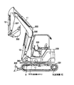
図2において、作業機械としてよく知られている油圧ショベルは、上部旋回体300と、下部走行体301と、スイング式のフロント作業機302を備え、フロント作業機302は、ブーム306、アーム307、バケット308から構成されている。上部旋回体300は下部走行体301を旋回モータ7の回転によって旋回可能である。上部旋回体300の前部にはスィングポスト303が取り付けられ、このスィングポスト303にフロント作業機302が上下動可能に取り付けられている。スイングポスト303はスイングシリンダ9(図1参照)の伸縮により上部旋回体300に対して水平方向に回動可能であり、フロント作業機302のブーム306、アーム307、バケット308はブームシリンダ10、アームシリンダ11、バケットシリンダ12の伸縮により上下方向に回動可能である。下部走行体301は中央フレーム304を備え、この中央フレーム304にはブレードシリンダ8(図1A参照)の伸縮により上下動作を行うブレード305が取り付けられている。下部走行体301は、走行モータ5,6の回転により左右の履帯310,311を駆動することによって走行を行う。
<第1の実施の形態>
図1Aに本発明の第1の実施の形態に係わる油圧ショベルの油圧駆動装置を示す。 In FIG. 2, a hydraulic excavator well known as a work machine includes anupper swing body 300, a lower traveling body 301, and a swing type front work machine 302. The front work machine 302 includes a boom 306, an arm 307, The bucket 308 is configured. The upper swing body 300 can swing the lower traveling body 301 by the rotation of the swing motor 7. A swing post 303 is attached to the front portion of the upper swing body 300, and a front work machine 302 is attached to the swing post 303 so as to be movable up and down. The swing post 303 can be rotated in the horizontal direction with respect to the upper swing body 300 by expansion and contraction of the swing cylinder 9 (see FIG. 1). The boom 306, the arm 307, and the bucket 308 of the front work machine 302 are the boom cylinder 10 and the arm. The cylinder 11 and the bucket cylinder 12 can be rotated in the vertical direction by expansion and contraction. The lower traveling body 301 includes a central frame 304, and a blade 305 that moves up and down by expansion and contraction of the blade cylinder 8 (see FIG. 1A) is attached to the central frame 304. The lower traveling body 301 travels by driving the left and right crawler belts 310 and 311 by the rotation of the traveling motors 5 and 6.
<First Embodiment>
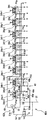
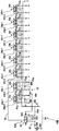
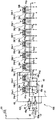
FIG. 1A shows a hydraulic drive device for a hydraulic excavator according to the first embodiment of the present invention.
<第1の実施の形態>
図1Aに本発明の第1の実施の形態に係わる油圧ショベルの油圧駆動装置を示す。 In FIG. 2, a hydraulic excavator well known as a work machine includes an
<First Embodiment>
FIG. 1A shows a hydraulic drive device for a hydraulic excavator according to the first embodiment of the present invention.
~基本構成~
まず、本実施の形態に係わる油圧駆動装置の基本構成を説明する。 ~ Basic configuration ~
First, the basic configuration of the hydraulic drive apparatus according to this embodiment will be described.
まず、本実施の形態に係わる油圧駆動装置の基本構成を説明する。 ~ Basic configuration ~
First, the basic configuration of the hydraulic drive apparatus according to this embodiment will be described.
本実施の形態における油圧駆動装置は、エンジン1と、エンジン1によって駆動されるメインの油圧ポンプ(以下メインポンプという)2と、メインポンプ2と連動してエンジン1により駆動されるパイロットポンプ3と、メインポンプ2から吐出された圧油により駆動される複数のアクチュエータ5,6,7,8,9,10,11,12である左右の走行モータ5,6、旋回モータ7、ブレードシリンダ8、スイングシリンダ9、ブームシリンダ10、アームシリンダ11、バケットシリンダ12と、コントロールバルブ4とを備えている。本実施形態に係わる油圧ショベルは、例えば油圧ミニショベルである。
The hydraulic drive apparatus according to the present embodiment includes an engine 1, a main hydraulic pump (hereinafter referred to as a main pump) 2 driven by the engine 1, and a pilot pump 3 driven by the engine 1 in conjunction with the main pump 2. , Left and right traveling motors 5, 6, turning motor 7, blade cylinder 8, which are a plurality of actuators 5, 6, 7, 8, 9, 10, 11, 12 driven by the pressure oil discharged from main pump 2. A swing cylinder 9, a boom cylinder 10, an arm cylinder 11, a bucket cylinder 12, and a control valve 4 are provided. The hydraulic excavator according to the present embodiment is, for example, a hydraulic mini excavator.
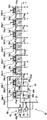
コントロールバルブ4は、メインポンプ2の供給油路2aに接続され、メインポンプ2から各アクチュエータに供給される圧油の方向と流量をそれぞれ制御する複数のバルブセクション13,14,15,16,17,18,19,20と、複数のアクチュエータ5,6,7,8,9,10,11,12の負荷圧のうち最も高い負荷圧(以下、最高負荷圧という)PLmaxを選択して信号油路21に出力する複数のシャトル弁22a,22b,22c,22d,22e,22f,22gと、メインポンプ2の供給油路2aに接続されたバルブ内供給油路4aに接続され、メインポンプ2の最高吐出圧(最高ポンプ圧)を制限するメインリリーフ弁23と、パイロット油圧源33(後述)に接続され、供給油路4a及び信号油路21の圧力を信号圧力として入力し、メインポンプ2の吐出圧(ポンプ圧)Pdと最高負荷圧PLmaxとの差圧PLSを絶対圧として出力する差圧減圧弁24と、バルブ内供給油路4aに接続され、供給油路4a及び信号油路21の圧力を信号圧力として入力し、ポンプ圧Pdと最高負荷圧PLmaxとの差圧PLSがバネ25aにより設定されたある一定値を超えたときにメインポンプ2の吐出流量の一部をタンクTに戻し、差圧PLSをバネ25aにより設定された一定値以下に保つアンロード弁25とを有している。アンロード弁25及びメインリリーフ弁23の出口側はバルブ内タンク油路29に接続され、この油路29を介してタンクTに接続されている。
The control valve 4 is connected to the supply oil passage 2a of the main pump 2, and has a plurality of valve sections 13, 14, 15, 16, 17 for controlling the direction and flow rate of the pressure oil supplied from the main pump 2 to each actuator. , 18, 19, 20 and a plurality of actuators 5, 6, 7, 8, 9, 10, 11, 12 to select the highest load pressure (hereinafter referred to as the maximum load pressure) PLmax and signal oil A plurality of shuttle valves 22 a, 22 b, 22 c, 22 d, 22 e, 22 f, and 22 g that are output to the passage 21 are connected to the supply oil passage 4 a that is connected to the supply oil passage 2 a of the main pump 2. It is connected to a main relief valve 23 that limits the maximum discharge pressure (maximum pump pressure) and a pilot hydraulic pressure source 33 (described later), and signals the pressure in the supply oil passage 4a and the signal oil passage 21. The pressure is input as a pressure, and is connected to a differential pressure reducing valve 24 that outputs a differential pressure PLS between the discharge pressure (pump pressure) Pd of the main pump 2 and the maximum load pressure PLmax as an absolute pressure, and a supply oil passage 4a in the valve to supply The pressure of the oil passage 4a and the signal oil passage 21 is input as a signal pressure, and when the differential pressure PLS between the pump pressure Pd and the maximum load pressure PLmax exceeds a certain value set by the spring 25a, the discharge of the main pump 2 An unload valve 25 is provided that returns a part of the flow rate to the tank T and keeps the differential pressure PLS below a predetermined value set by the spring 25a. The outlet sides of the unload valve 25 and the main relief valve 23 are connected to a tank oil passage 29 in the valve, and are connected to the tank T through the oil passage 29.
バルブセクション13は流量制御弁26aと圧力補償弁27aとから構成され、バルブセクション14は流量制御弁26bと圧力補償弁27bとから構成され、バルブセクション15は流量制御弁26cと圧力補償弁27cとから構成され、バルブセクション16は流量制御弁26dと圧力補償弁27dとから構成され、バルブセクション17は流量制御弁26eと圧力補償弁27eとから構成され、バルブセクション18は流量制御弁26fと圧力補償弁27fとから構成され、バルブセクション19は流量制御弁26gと圧力補償弁27gとから構成され、バルブセクション20は流量制御弁26hと圧力補償弁27hとから構成されている。
The valve section 13 includes a flow control valve 26a and a pressure compensation valve 27a, the valve section 14 includes a flow control valve 26b and a pressure compensation valve 27b, and the valve section 15 includes a flow control valve 26c and a pressure compensation valve 27c. The valve section 16 is composed of a flow control valve 26d and a pressure compensation valve 27d, the valve section 17 is composed of a flow control valve 26e and a pressure compensation valve 27e, and the valve section 18 is composed of a flow control valve 26f and a pressure. The valve section 19 includes a flow rate control valve 26g and a pressure compensation valve 27g, and the valve section 20 includes a flow rate control valve 26h and a pressure compensation valve 27h.
流量制御弁26a~26hは、メインポンプ2からそれぞれのアクチュエータ5~12に供給される圧油の方向と流量をそれぞれ制御し、圧力補償弁27a~27hは流量制御弁26a~26hの前後差圧をそれぞれ制御する。
The flow control valves 26a to 26h control the direction and flow rate of the pressure oil supplied from the main pump 2 to the actuators 5 to 12, respectively. The pressure compensation valves 27a to 27h are differential pressures before and after the flow control valves 26a to 26h. To control each.
圧力補償弁27a~27hは目標差圧設定用の開弁側受圧部28a,28b,28c,28d,28e,28f,28g,28hを有し、この受圧部28a~28hには差圧減圧弁24の出力圧が導かれ、油圧ポンプ圧Pdと最高負荷圧PLmaxとの差圧PLSの絶対圧(以下絶対圧PLSという)により目標補償差圧が設定される。このように流量制御弁26a~26hの前後差圧を同じ差圧PLSという値に制御することにより、圧力補償弁27a~27hは流量制御弁26a~26hの前後差圧が油圧ポンプ圧Pdと最高負荷圧PLmaxとの差圧PLSに等しくなるように制御する。これにより複数のアクチュエータを同時に駆動する複合操作時は、アクチュエータ5~12の負荷圧の大小に係わらず、流量制御弁26a~26hの開口面積比に応じてメインポンプ2の吐出流量を分配し、複合操作性を確保することができる。また、メインポンプ2の吐出流量が要求流量に満たないサチュレーション状態になった場合は、差圧PLSはその供給不足の程度に応じて低下し、これに応じて圧力補償弁27a~27hが制御する流量制御弁26a~26hの前後差圧が同じ割合で低下して流量制御弁26a~26hの通過流量が同じ割合で減少するため、この場合も流量制御弁26a~26hの開口面積比に応じてメインポンプ2吐出流量を分配し、複合操作性を確保することができる。
The pressure compensating valves 27a to 27h have valve-opening side pressure receiving portions 28a, 28b, 28c, 28d, 28e, 28f, 28g, and 28h for setting a target differential pressure. The pressure receiving portions 28a to 28h include a differential pressure reducing valve 24. The target compensation differential pressure is set by the absolute pressure of the differential pressure PLS between the hydraulic pump pressure Pd and the maximum load pressure PLmax (hereinafter referred to as the absolute pressure PLS). By thus controlling the differential pressure across the flow control valves 26a-26h to the same differential pressure PLS, the pressure compensation valves 27a-27h have the maximum differential pressure across the flow control valves 26a-26h equal to the hydraulic pump pressure Pd. Control is performed so as to be equal to the differential pressure PLS from the load pressure PLmax. As a result, during the combined operation of simultaneously driving a plurality of actuators, the discharge flow rate of the main pump 2 is distributed according to the opening area ratio of the flow rate control valves 26a to 26h regardless of the load pressure of the actuators 5 to 12. Combined operability can be ensured. When the discharge flow rate of the main pump 2 reaches a saturation state where the required flow rate is less than the required flow rate, the differential pressure PLS decreases according to the degree of supply shortage, and the pressure compensation valves 27a to 27h control accordingly. Since the differential pressure across the flow control valves 26a to 26h decreases at the same rate and the flow rate through the flow control valves 26a to 26h decreases at the same rate, in this case as well, depending on the opening area ratio of the flow control valves 26a to 26h. The discharge flow rate of the main pump 2 can be distributed to ensure composite operability.
圧力補償弁27a~27hは、図1Aのシンボル表示から分かるように、開口面積減少方向(図示左方向)のストロークエンドにおいて全閉しないタイプの圧力補償弁である。
As can be seen from the symbol display in FIG. 1A, the pressure compensation valves 27a to 27h are pressure compensation valves that do not fully close at the stroke end in the direction of decreasing the opening area (the left direction in the figure).
また、油圧駆動装置は、パイロットポンプ3の供給油路3aに接続され、パイロットポンプ3の吐出流量に応じて絶対圧を出力するエンジン回転数検出弁30と、エンジン回転数検出弁30の下流側に接続され、パイロット油路31の圧力を一定に保つパイロットリリーフ弁32を有するパイロット油圧源33と、パイロット油路31に接続され、パイロット油圧源32の圧力を元圧(パイロット一次圧)として流量制御弁26a~26hを操作するための操作パイロット圧(パイロット二次圧)a,b,c,d,e,f,g,h,i,j,k,l,m,n,o,pを生成するためのリモコン弁34a-2,34b-2,34c-2,34d-2,34e-2,34f-2,34g-2,34h-2(図1B参照)を備えた操作装置34a,34b,34c,34d,34e,34f,34g,34hとを備えている。
The hydraulic drive device is connected to the supply oil passage 3 a of the pilot pump 3, and outputs the absolute pressure according to the discharge flow rate of the pilot pump 3, and the downstream side of the engine speed detection valve 30. And a pilot hydraulic pressure source 33 having a pilot relief valve 32 that keeps the pressure of the pilot oil passage 31 constant, and a flow rate that is connected to the pilot oil passage 31 and uses the pressure of the pilot hydraulic pressure source 32 as an original pressure (pilot primary pressure). Operating pilot pressures (pilot secondary pressures) a, b, c, d, e, f, g, h, i, j, k, l, m, n, o, p for operating the control valves 26a to 26h Operating device 34a provided with remote control valves 34a-2, 34b-2, 34c-2, 34d-2, 34e-2, 34f-2, 34g-2, 34h-2 (see FIG. 1B) 34b, and includes 34c, 34d, 34e, 34f, 34g, and 34h.
エンジン回転数検出弁30は、パイロットポンプ3の供給油路3aをパイロット油路31に接続する油路に設けられた絞り要素(固定絞り部)30fと、絞り要素30fに並列に接続された流量検出弁30aと、差圧減圧弁30bとを有している。流量検出弁30aの入力側はパイロットポンプ3の供給油路3aに接続され、流量検出弁30aの出力側はパイロット油路31に接続されている。流量検出弁30aは通過流量が増大するにしたがって開口面積を大きくする可変絞り部30cを有し、パイロットポンプ3の吐出油は絞り要素30f及び流量検出弁30aの可変絞り部30cの両方を通過してパイロット油路31側へと流れる。このとき、絞り要素30fと流量検出弁30aの可変絞り部30cには通過流量が増加するにしたがって大きくなる前後差圧が発生し、差圧減圧弁30bはその前後差圧を絶対圧Paとして出力する。パイロットポンプ3の吐出流量はエンジン1の回転数によって変化するため、絞り要素30f及び可変絞り部30cの前後差圧を検出することにより、パイロットポンプ3の吐出流量を検出することができ、エンジン1の回転数を検出することができる。また、可変絞り部30cは、通過流量が増大するにしたがって(前後差圧が高くなるにしたがって)開口面積を大きくすることにより、通過流量が増大するにしたがって前後差圧の上昇度合いが緩やかになるように構成されている。
The engine speed detection valve 30 includes a throttle element (fixed throttle part) 30f provided in an oil path connecting the supply oil path 3a of the pilot pump 3 to the pilot oil path 31, and a flow rate connected in parallel to the throttle element 30f. It has a detection valve 30a and a differential pressure reducing valve 30b. The input side of the flow rate detection valve 30 a is connected to the supply oil passage 3 a of the pilot pump 3, and the output side of the flow rate detection valve 30 a is connected to the pilot oil passage 31. The flow rate detection valve 30a has a variable throttle portion 30c that increases the opening area as the passing flow rate increases, and the discharge oil of the pilot pump 3 passes through both the throttle element 30f and the variable throttle portion 30c of the flow rate detection valve 30a. Flow to the pilot oil passage 31 side. At this time, a differential pressure increases and decreases as the passing flow rate increases in the throttle element 30f and the variable throttle portion 30c of the flow rate detection valve 30a, and the differential pressure reducing valve 30b outputs the differential pressure as the absolute pressure Pa. To do. Since the discharge flow rate of the pilot pump 3 varies depending on the rotation speed of the engine 1, the discharge flow rate of the pilot pump 3 can be detected by detecting the differential pressure across the throttle element 30f and the variable throttle portion 30c. The number of rotations can be detected. Further, the variable throttle portion 30c increases the opening area as the passing flow rate increases (as the front-rear differential pressure increases), so that the degree of increase in the front-rear differential pressure becomes milder as the passing flow rate increases. It is configured as follows.
メインポンプ2は可変容量型の油圧ポンプであり、その傾転角(容量)を制御するためのポンプ制御装置35を備えている。ポンプ制御装置35はポンプトルク制御部35AとLS制御部35Bとで構成されている。
The main pump 2 is a variable displacement hydraulic pump, and includes a pump control device 35 for controlling the tilt angle (capacity) thereof. The pump control device 35 includes a pump torque control unit 35A and an LS control unit 35B.
ポンプトルク制御部35Aはトルク制御傾転アクチュエータ35aを有し、トルク制御傾転アクチュエータ35aはメインポンプ2の吐出圧が高くなるとメインポンプ2の傾転角(容量)が減るようにメインポンプ2の斜板(容量可変部材)2sを駆動し、メインポンプ2の入力トルクが予め設定した最大トルクを越えないように制限する。これによりメインポンプ2の消費馬力が制限され、過負荷によるエンジン1の停止(エンジンストール)が防止される。
The pump torque control unit 35A includes a torque control tilt actuator 35a, and the torque control tilt actuator 35a is configured so that the tilt angle (capacity) of the main pump 2 decreases as the discharge pressure of the main pump 2 increases. The swash plate (capacity variable member) 2s is driven, and the input torque of the main pump 2 is limited so as not to exceed the preset maximum torque. Thereby, the horsepower consumption of the main pump 2 is limited, and the stop (engine stall) of the engine 1 due to overload is prevented.
LS制御部35Bは、LS制御弁35b及びLS制御傾転アクチュエータ35cを有している。
The LS control unit 35B includes an LS control valve 35b and an LS control tilt actuator 35c.
LS制御弁35bは対向する受圧部35d,35eを有し、受圧部35dには油路40を介してエンジン回転数検出弁30の差圧減圧弁30bで生成された絶対圧Paがロードセンシング制御の目標差圧(目標LS差圧)として導かれ、受圧部35eに差圧減圧弁24で生成された絶対圧PLS(メインポンプ2の吐出圧Pdと最高負荷圧PLmaxとの差圧PLS)がフィードバック差圧として導かれる。LS制御弁35bは、絶対圧PLSが絶対圧Paよりも高くなると(PLS>Pa)、パイロット油圧源33の圧力をLS制御傾転アクチュエータ35cに導き、絶対圧PLSが絶対圧Paよりも低くなると(PLS<Pa)、LS制御傾転アクチュエータ35cをタンクTに連通させる。LS制御傾転アクチュエータ35cは、パイロット油圧源33の圧力が導かれると、メインポンプ2の傾転角が減るようにメインポンプ2の斜板2sを駆動し、タンクTに連通すると、メインポンプ2の傾転角が増えるようにメインポンプ2の斜板2sを駆動する。これによりメインポンプ2の吐出圧Pdが最高負荷圧PLmaxよりも絶対圧Pa(目標差圧)だけ高くなるようにメインポンプ2の傾転角(容量)が制御される。
The LS control valve 35b has pressure receiving portions 35d and 35e facing each other, and the pressure receiving portion 35d receives the absolute pressure Pa generated by the differential pressure reducing valve 30b of the engine speed detection valve 30 via the oil passage 40. The absolute pressure PLS (the differential pressure PLS between the discharge pressure Pd of the main pump 2 and the maximum load pressure PLmax) generated by the differential pressure reducing valve 24 in the pressure receiving portion 35e is guided as a target differential pressure (target LS differential pressure). Guided as feedback differential pressure. When the absolute pressure PLS becomes higher than the absolute pressure Pa (PLS> Pa), the LS control valve 35b guides the pressure of the pilot hydraulic source 33 to the LS control tilt actuator 35c, and the absolute pressure PLS becomes lower than the absolute pressure Pa. (PLS <Pa), the LS control tilt actuator 35c is communicated with the tank T. The LS control tilt actuator 35c drives the swash plate 2s of the main pump 2 so that the tilt angle of the main pump 2 decreases when the pressure of the pilot hydraulic power source 33 is guided. The swash plate 2s of the main pump 2 is driven so as to increase the tilt angle. As a result, the tilt angle (capacity) of the main pump 2 is controlled so that the discharge pressure Pd of the main pump 2 becomes higher than the maximum load pressure PLmax by the absolute pressure Pa (target differential pressure).
ここで、絶対圧Paはエンジン回転数に応じて変化する値であるため、絶対圧Paをロードセンシング制御の目標差圧として用い、圧力補償弁27a~27hの目標補償差圧をメインポンプ2の吐出圧Pdと最高負荷圧PLmaxとの差圧の絶対圧PLSにより設定することにより、エンジン回転数に応じたアクチュエータスピードの制御が可能となる。
Here, since the absolute pressure Pa is a value that changes according to the engine speed, the absolute pressure Pa is used as the target differential pressure of the load sensing control, and the target compensated differential pressure of the pressure compensating valves 27a to 27h is used for the main pump 2. By setting the absolute pressure PLS as the differential pressure between the discharge pressure Pd and the maximum load pressure PLmax, the actuator speed can be controlled according to the engine speed.
アンロード弁25のバネ25aの設定圧は、エンジン1が定格最高回転数にあるときのエンジン回転数検出弁30の差圧減圧弁30bで生成された絶対圧Pa(ロードセンシング制御の目標差圧)よりも少し高くなるように設定されている。
The set pressure of the spring 25a of the unload valve 25 is the absolute pressure Pa (target differential pressure for load sensing control) generated by the differential pressure reducing valve 30b of the engine speed detecting valve 30 when the engine 1 is at the rated maximum speed. ) Is set to be slightly higher.
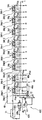
図1Bは、操作装置34a,34b,34c,34d,34e,34f,34g,34hとそのパイロット回路部分を拡大して示す図である。
FIG. 1B is an enlarged view of the operation devices 34a, 34b, 34c, 34d, 34e, 34f, 34g, and 34h and their pilot circuit portions.
操作装置34aは、操作レバー34a-1とリモコン弁34a-2を有し、リモコン弁34a-2は1対の減圧弁PVa,PVbを備えている。操作レバー34a-1を図示右方向に操作するとリモコン弁34a-2の減圧弁PVaが作動して操作レバー34a-1の操作量に応じた大きさの操作パイロット圧aを生成し、操作レバー34a-1を図示左方向に操作するとリモコン弁34a-2の減圧弁PVbが作動して操作レバー34a-1の操作量に応じた大きさの操作パイロット圧bを生成する。
The operating device 34a has an operating lever 34a-1 and a remote control valve 34a-2, and the remote control valve 34a-2 includes a pair of pressure reducing valves PVa and PVb. When the operation lever 34a-1 is operated rightward in the figure, the pressure reducing valve PVa of the remote control valve 34a-2 is activated to generate an operation pilot pressure a having a magnitude corresponding to the operation amount of the operation lever 34a-1, and the operation lever 34a When -1 is operated in the left direction in the figure, the pressure reducing valve PVb of the remote control valve 34a-2 is activated to generate an operating pilot pressure b having a magnitude corresponding to the operating amount of the operating lever 34a-1.
操作装置34b~34hも同様に構成されている。すなわち、操作装置34b~34hは、それぞれ、操作レバー34b-1,34c-1,34d-1,34e-1,34f-1,34g-1,34h-1とリモコン弁34b-2,34c-2,34d-2,34e-2,34f-2,34g-2,34h-2を有し、操作レバー34b-1,34c-1,34d-1,34e-1,34f-1,34g-1,34h-1を図示右方向に操作するとリモコン弁34b-2,34c-2,34d-2,34e-2,34f-2,34g-2,34h-2の減圧弁PVc,PVe,PVg,PVi,PVk,PVm,PVoがそれぞれ作動して操作レバー34b-1,34c-1,34d-1,34e-1,34f-1,34g-1,34h-1の操作量に応じた大きさの操作パイロット圧c,e,g,i,k,m,oを生成し、操作レバー34b-1,34c-1,34d-1,34e-1,34f-1,34g-1,34h-1を図示左方向に操作するとリモコン弁34b-2,34c-2,34d-2,34e-2,34f-2,34g-2,34h-2の減圧弁PVd,PVf,PVh,PVj,PVl,PVn,PVpがそれぞれ作動して操作レバー34b-1,34c-1,34d-1,34e-1,34f-1,34g-1,34h-1の操作量に応じた大きさの操作パイロット圧d,f,h,j,l,n,pを生成する。
The operation devices 34b to 34h are configured similarly. That is, the operating devices 34b to 34h are respectively provided with operating levers 34b-1, 34c-1, 34d-1, 34e-1, 34f-1, 34g-1, 34h-1, and remote control valves 34b-2, 34c-2. , 34d-2, 34e-2, 34f-2, 34g-2, 34h-2 and operating levers 34b-1, 34c-1, 34d-1, 34e-1, 34f-1, 34g-1, When operating 34h-1 in the right direction in the figure, the pressure reducing valves PVc, PVe, PVg, PVi, remote control valves 34b-2, 34c-2, 34d-2, 34e-2, 34f-2, 34g-2, 34h-2, PVk, PVm, and PVo are actuated to operate pilots having sizes corresponding to the operation amounts of the operation levers 34b-1, 34c-1, 34d-1, 34e-1, 34f-1, 34g-1, and 34h-1, respectively. Pressure c, e When g, i, k, m, o are generated and the operation levers 34b-1, 34c-1, 34d-1, 34e-1, 34f-1, 34g-1, 34h-1 are operated in the left direction in the figure, the remote controller Valves 34b-2, 34c-2, 34d-2, 34e-2, 34f-2, 34g-2, 34h-2 are operated by operating the pressure reducing valves PVd, PVf, PVh, PVj, PVl, PVn, PVp, respectively. The operating pilot pressures d, f, h, j, l having magnitudes corresponding to the operating amounts of the levers 34b-1, 34c-1, 34d-1, 34e-1, 34f-1, 34g-1, 34h-1 n and p are generated.
~特徴的構成~
次に、本実施の形態に係わる油圧駆動装置の特徴的構成を説明する。 -Characteristic configuration-
Next, a characteristic configuration of the hydraulic drive device according to the present embodiment will be described.
次に、本実施の形態に係わる油圧駆動装置の特徴的構成を説明する。 -Characteristic configuration-
Next, a characteristic configuration of the hydraulic drive device according to the present embodiment will be described.
本実施の形態に係わる油圧駆動装置は、その特徴的構成として、操作装置34a,34b,34c,34d,34e,34f,34g,34hのリモコン弁34b-2,34c-2,34d-2,34e-2,34f-2,34g-2,34h-2にパイロット油圧源33の圧力であるパイロット一次圧を供給するパイロット一次圧回路40を備え、このパイロット一次圧回路40は、走行の操作装置34a,34bのリモコン弁34a-2,34b-2にパイロット一次圧を供給する第1回路41と、走行操作装置以外の操作装置(以下単に走行以外の操作装置という)34c~34hのリモコン弁34c-2~34h-2にパイロット一次圧を供給する第2回路42とを有している。
The hydraulic drive device according to the present embodiment has, as a characteristic configuration, a remote control valve 34b-2, 34c-2, 34d-2, 34e of the operation devices 34a, 34b, 34c, 34d, 34e, 34f, 34g, 34h. -2, 34 f-2, 34 g-2, and 34 h-2 are provided with a pilot primary pressure circuit 40 that supplies a pilot primary pressure that is the pressure of the pilot hydraulic pressure source 33, and the pilot primary pressure circuit 40 includes a traveling operation device 34 a. 34b, remote control valves 34a-2 and 34b-2, a first circuit 41 for supplying pilot primary pressure, and operation devices other than the travel operation device (hereinafter simply referred to as operation devices other than travel) 34c to 34h. And a second circuit 42 for supplying pilot primary pressure to 2 to 34h-2.
第2回路42は、走行の操作装置34a,34bが操作されていないときは、パイロット一次圧をそのまま走行以外の操作装置34c~34hのリモコン弁34c-2~34h-2に供給し、走行の操作装置34a,34bが操作されたときは、パイロット一次圧を減圧して走行以外の操作装置34c~34hのリモコン弁34c-2~34h-2に供給するよう構成されている。
When the travel operation devices 34a and 34b are not operated, the second circuit 42 supplies the pilot primary pressure as it is to the remote control valves 34c-2 to 34h-2 of the operation devices 34c to 34h other than the travel. When the operating devices 34a and 34b are operated, the pilot primary pressure is reduced and supplied to the remote control valves 34c-2 to 34h-2 of the operating devices 34c to 34h other than traveling.
走行モータ5,6は特定のアクチュエータであり、走行の操作装置34a,34bは、複数の操作装置34a~34hのうち特定のアクチュエータ(走行モータ5,6)に対応する特定の操作装置である。また、本明細書において特定のアクチュエータとは、その特定のアクチュエータと他のアクチュエータとを同時に駆動する複合操作をしたときに他のアクチュエータが低負荷圧側となり、かつ特定のアクチュエータの負荷圧が、他のアクチュエータ(低負荷側のアクチュエータ)の圧力補償弁がストロークエンド付近まで動作する程度にまで高くなるアクチュエータを言う。
The travel motors 5 and 6 are specific actuators, and the travel operation devices 34a and 34b are specific operation devices corresponding to specific actuators (travel motors 5 and 6) among the plurality of operation devices 34a to 34h. Also, in this specification, a specific actuator means that the other actuator is on the low load pressure side when the combined operation of simultaneously driving the specific actuator and the other actuator is performed, and the load pressure of the specific actuator is other than This is an actuator that becomes so high that the pressure compensation valve of the actuator (actuator on the low load side) operates to near the stroke end.
また、本実施の形態に係わる油圧駆動装置は、走行の操作装置34a,34bの操作を検出する操作検出装置43を更に備え、この操作検出装置43は、走行の操作装置34a,34bのリモコン弁34a-2,34b-2が生成する操作パイロット圧(走行の操作パイロット圧)を検出して油圧信号として出力するシャトル弁48a,48b,48cを有している。第2回路42は、パイロット一次圧をそのまま導く第3回路44と、パイロット一次圧を減圧して導く第4回路45と、第3回路44の圧力と第4回路45の圧力とを切り換えて走行以外の操作装置34c~34hのリモコン弁34c-2~34h-2に導く切換弁46とを備え、第4回路45はパイロット一次圧を減圧する減圧弁47を有し、切換弁46はシャトル弁48a,48b,48cからの油圧信号が油路48dを介して導かれるパイロット受圧部46aを有している。
The hydraulic drive apparatus according to the present embodiment further includes an operation detection device 43 that detects the operation of the travel operation devices 34a and 34b. The operation detection device 43 is a remote control valve for the travel operation devices 34a and 34b. Shuttle valves 48a, 48b, and 48c that detect the operation pilot pressure (traveling operation pilot pressure) generated by 34a-2 and 34b-2 and output them as hydraulic signals are provided. The second circuit 42 travels by switching the pressure of the third circuit 44 and the pressure of the fourth circuit 45, the third circuit 44 that guides the pilot primary pressure as it is, the fourth circuit 45 that guides the pilot primary pressure by reducing it. And a switching valve 46 that leads to the remote control valves 34c-2 to 34h-2 of the operating devices 34c to 34h other than the above, the fourth circuit 45 has a pressure reducing valve 47 that reduces the pilot primary pressure, and the switching valve 46 is a shuttle valve. There is a pilot pressure receiving portion 46a through which oil pressure signals from 48a, 48b and 48c are guided through an oil passage 48d.
走行の操作装置34a,34bの操作レバー34a-1,34b-1が操作されておらず、走行の操作パイロット圧が生成されていないときは、切換弁46は図示右側の第1位置にあり、第3回路44が走行以外の操作装置34c~34hのリモコン弁34c-2~34h-2に至る回路49に連通し、パイロット一次圧がそのまま走行以外の操作装置34c~34hのリモコン弁34c-2~34h-2に導かれる。走行の操作装置34a,34bの操作レバー34a-1,34b-1が操作され、走行の操作パイロット圧が生成されるときは、走行の操作パイロット圧が切換弁46のパイロット受圧部46aに導かれ、切換弁46は図示左側の第2位置に切り換わり、第4回路45が走行以外の操作装置34c~34hのリモコン弁34c-2~34h-2に至る回路49に連通し、パイロット一次圧が減圧弁47で減圧されて走行以外の操作装置34c~34hのリモコン弁34c-2~34h-2に導かれる。
When the operation levers 34a-1 and 34b-1 of the travel operation devices 34a and 34b are not operated and the travel operation pilot pressure is not generated, the switching valve 46 is in the first position on the right side of the figure, The third circuit 44 communicates with a circuit 49 that leads to the remote control valves 34c-2 to 34h-2 of the operating devices 34c to 34h other than traveling, and the pilot primary pressure remains as it is as the remote control valve 34c-2 of the operating devices 34c to 34h other than traveling. To 34h-2. When the operation levers 34a-1 and 34b-1 of the travel operation devices 34a and 34b are operated to generate a travel operation pilot pressure, the travel operation pilot pressure is guided to the pilot pressure receiving portion 46a of the switching valve 46. The switching valve 46 is switched to the second position on the left side of the figure, and the fourth circuit 45 communicates with the circuit 49 leading to the remote control valves 34c-2 to 34h-2 of the operating devices 34c to 34h other than traveling, and the pilot primary pressure is The pressure is reduced by the pressure reducing valve 47 and guided to the remote control valves 34c-2 to 34h-2 of the operating devices 34c to 34h other than traveling.
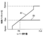
図3A~図3Cは、そのときの操作装置34c~34hのレバー操作量に対する流量制御弁26c~26hの開口面積の変化を示す図である。
3A to 3C are diagrams showing changes in the opening areas of the flow control valves 26c to 26h with respect to the lever operation amounts of the operation devices 34c to 34h at that time.
走行の操作装置34a,34bの操作レバー34a-1,34b-1が操作されていないときは、走行の操作パイロット圧が生成されないため、切換弁46は図示右側の第1位置にあり、パイロット油圧源33のパイロット一次圧がそのまま走行以外の操作装置34c~34hのリモコン弁34c-2~34h-2に導かれる。これにより走行以外の操作装置34c~34hの操作レバー34c-1~34h-1が操作されたとき、リモコン弁34c-2~34h-2が生成する操作パイロット圧、走行以外の流量制御弁26c~26hのスプールストローク及び開口面積は、それぞれ、図3Aの特性A1、図3Bの特性A2及び図3Cの特性A3に示すように変化する。すなわち、レバー操作量が増大するにしたがって操作パイロット圧は最小圧力Ppminから最大圧力Ppmaxまで増大し(図3Aの特性A1)、操作パイロット圧が増大するにしたがって走行以外の流量制御弁26c~26hのスプールストロークはゼロから最大Smaxまで増大し(図3Bの特性A2)、スプールストロークが増大するにしたがってメータインの開口面積はゼロから最大Amaxまで増大する(図3Cの特性A3)。
When the operating levers 34a-1 and 34b-1 of the traveling operation devices 34a and 34b are not operated, the traveling operation pilot pressure is not generated, and therefore the switching valve 46 is in the first position on the right side of the drawing, and the pilot hydraulic pressure The pilot primary pressure of the source 33 is introduced as it is to the remote control valves 34c-2 to 34h-2 of the operating devices 34c to 34h other than traveling. Thus, when the operation levers 34c-1 to 34h-1 of the operation devices 34c to 34h other than traveling are operated, the operation pilot pressure generated by the remote control valves 34c-2 to 34h-2 and the flow control valves 26c to 26c other than traveling are controlled. The spool stroke and opening area of 26h change as indicated by a characteristic A1 in FIG. 3A, a characteristic A2 in FIG. 3B, and a characteristic A3 in FIG. 3C, respectively. That is, as the lever operation amount increases, the operation pilot pressure increases from the minimum pressure Ppmin to the maximum pressure Ppmax (characteristic A1 in FIG. 3A), and the flow control valves 26c to 26h other than traveling increase as the operation pilot pressure increases. The spool stroke increases from zero to the maximum Smax (characteristic A2 in FIG. 3B), and as the spool stroke increases, the meter-in opening area increases from zero to the maximum Amax (characteristic A3 in FIG. 3C).
一方、走行の操作装置34a,34bの操作レバー34a-1,34b-1が操作されたときは、走行の操作パイロット圧が生成されて切換弁46は図示左側の第2位置に切り換わってパイロット油圧源33のパイロット一次圧が減圧されるため、走行以外の操作装置34c~34hの操作レバー34c-1~34h-1が操作されたとき、リモコン弁34c-2~34h-2が生成する操作パイロット圧、走行以外の流量制御弁26c~26hのスプールストローク及び開口面積は、それぞれ、図3Aの特性B1、図3Bの特性B2及び図3Cの特性B3に示すように変化する。すなわち、レバー操作量が増大するにしたがって操作パイロット圧は増大するが、レバー操作量が中間の操作量Xaまで増大して操作パイロット圧がPpaまで上昇すると、レバー操作量をそれ以上増大させても操作パイロット圧はそれ以上増大せず、操作パイロット圧はPpaで一定である(図3Aの特性B1)。操作パイロット圧Ppaはパイロット一次圧の減圧された圧力(減圧弁47により減圧された圧力)に等しい圧力である。
On the other hand, when the operation levers 34a-1 and 34b-1 of the travel operation devices 34a and 34b are operated, the travel operation pilot pressure is generated, and the switching valve 46 is switched to the second position on the left side of the figure to thereby change the pilot. Since the pilot primary pressure of the hydraulic pressure source 33 is reduced, the operation generated by the remote control valves 34c-2 to 34h-2 when the operation levers 34c-1 to 34h-1 of the operation devices 34c to 34h other than traveling are operated. The spool stroke and the opening area of the flow rate control valves 26c to 26h other than the pilot pressure and the running change as shown by a characteristic B1 in FIG. 3A, a characteristic B2 in FIG. 3B, and a characteristic B3 in FIG. 3C, respectively. That is, as the lever operation amount increases, the operation pilot pressure increases. However, if the lever operation amount increases to the intermediate operation amount Xa and the operation pilot pressure increases to Ppa, the lever operation amount can be further increased. The operating pilot pressure does not increase any more, and the operating pilot pressure is constant at Ppa (characteristic B1 in FIG. 3A). The operating pilot pressure Ppa is a pressure equal to the pressure reduced by the pilot primary pressure (pressure reduced by the pressure reducing valve 47).
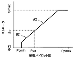
その結果、走行以外の流量制御弁26c~26hのスプールストロークはゼロから操作パイロット圧Ppaに相当する中間ストロークStrまでしか増大せず、走行以外の流量制御弁26c~26hの最大ストロークは中間ストロークStrに制限され(図3Bの特性B2)、メータインの最大開口面積も中間ストロークStrに対応する中間の開口面積Astrに制限される(図3Cの特性B3)。これにより走行の操作装置34a,34bの操作レバー34a-1,34b-1を操作して走行を行っているときは、走行以外の操作装置34c~34hの操作レバー34c-1~34h-1を操作しても、走行以外の流量制御弁26c~26hのメータインの開口面積は絞られ、流量制御弁26c~26hの要求流量は制限される。
As a result, the spool stroke of the flow control valves 26c to 26h other than traveling increases only from zero to the intermediate stroke Str corresponding to the operating pilot pressure Ppa, and the maximum stroke of the flow control valves 26c to 26h other than traveling is the intermediate stroke Str. (Characteristic B2 in FIG. 3B), and the maximum opening area of the meter-in is also limited to an intermediate opening area Astr corresponding to the intermediate stroke Str (characteristic B3 in FIG. 3C). As a result, when the travel levers 34a-1 and 34b-1 of the travel operation devices 34a and 34b are operated, the operation levers 34c-1 to 34h-1 of the operation devices 34c to 34h other than the travel are operated. Even if the operation is performed, the meter-in opening area of the flow control valves 26c to 26h other than traveling is restricted, and the required flow rates of the flow control valves 26c to 26h are limited.
~基本構成の動作~
まず、本実施の形態の油圧駆動装置の基本構成の動作を説明する。 -Basic configuration operation-
First, the operation of the basic configuration of the hydraulic drive apparatus according to the present embodiment will be described.
まず、本実施の形態の油圧駆動装置の基本構成の動作を説明する。 -Basic configuration operation-
First, the operation of the basic configuration of the hydraulic drive apparatus according to the present embodiment will be described.
<全ての操作レバーが中立のとき>
全ての操作装置34a~34hの操作レバー34a-1~34h-1が中立位置にある場合、全ての流量制御弁26a~26hは中立位置にあり、アクチュエータ5~12に圧油は供給されない。また、流量制御弁26a~26hが中立位置にあるときは、シャトル弁22a~22gにより検出される最高負荷圧PLmaxはタンク圧となる。 <When all control levers are neutral>
When the operation levers 34a-1 to 34h-1 of all theoperation devices 34a to 34h are in the neutral position, all the flow control valves 26a to 26h are in the neutral position, and no pressure oil is supplied to the actuators 5 to 12. When the flow control valves 26a to 26h are in the neutral position, the maximum load pressure PLmax detected by the shuttle valves 22a to 22g is the tank pressure.
全ての操作装置34a~34hの操作レバー34a-1~34h-1が中立位置にある場合、全ての流量制御弁26a~26hは中立位置にあり、アクチュエータ5~12に圧油は供給されない。また、流量制御弁26a~26hが中立位置にあるときは、シャトル弁22a~22gにより検出される最高負荷圧PLmaxはタンク圧となる。 <When all control levers are neutral>
When the operation levers 34a-1 to 34h-1 of all the
メインポンプ2からの吐出油は供給油路2a,4aに供給され、供給油路2a,4aの圧力が上昇する。供給油路4aにはアンロード弁25が設けられており、アンロード弁25は、供給油路2aの圧力が最高負荷圧PLmax(今の場合はタンク圧)よりバネ25aの設定圧以上高くなると、開状態になって供給油路2aの圧油をタンクに戻し、供給油路2aの圧力の上昇を制限する。これによりメインポンプ2の吐出圧は最低圧力Pminに制御される。
The oil discharged from the main pump 2 is supplied to the supply oil passages 2a and 4a, and the pressure in the supply oil passages 2a and 4a increases. The supply oil passage 4a is provided with an unload valve 25. When the pressure in the supply oil passage 2a becomes higher than the maximum load pressure PLmax (in this case, the tank pressure) by more than the set pressure of the spring 25a. The pressure oil in the supply oil passage 2a is returned to the tank in an open state, and the increase in the pressure in the supply oil passage 2a is restricted. Thereby, the discharge pressure of the main pump 2 is controlled to the minimum pressure Pmin.
差圧減圧弁24は、メインポンプ2の吐出圧Pdと最高負荷圧PLmax(今の場合はタンク圧)の差圧PLSを絶対圧として出力している。メインポンプ2のLS制御部35BのLS制御弁35bには、エンジン回転数検出弁30の出力圧と差圧減圧弁24の出力圧が導かれており、メインポンプ2の吐出圧が上昇し、差圧減圧弁24の出力圧がエンジン回転数検出弁30の出力圧よりも大きくなると、LS制御弁35bは図示右側の位置に切り換わり、LS制御傾転アクチュエータ35cにパイロット油圧源33の圧力が導かれ、メインポンプ2の傾転角が小さくなるよう制御される。しかし、メインポンプ2には、その最小傾転角を規定するストッパ(図示せず)が設けられているため、メインポンプ2はそのストッパにより規定される最小傾転角qminに保持され、最少流量Qminを吐出する。
The differential pressure reducing valve 24 outputs a differential pressure PLS between the discharge pressure Pd of the main pump 2 and the maximum load pressure PLmax (in this case, tank pressure) as an absolute pressure. The output pressure of the engine speed detection valve 30 and the output pressure of the differential pressure reducing valve 24 are guided to the LS control valve 35b of the LS control unit 35B of the main pump 2, and the discharge pressure of the main pump 2 increases. When the output pressure of the differential pressure reducing valve 24 becomes larger than the output pressure of the engine speed detection valve 30, the LS control valve 35b is switched to the right position in the figure, and the pressure of the pilot hydraulic power source 33 is applied to the LS control tilt actuator 35c. It is guided and controlled so that the tilt angle of the main pump 2 becomes small. However, since the main pump 2 is provided with a stopper (not shown) that defines the minimum tilt angle, the main pump 2 is held at the minimum tilt angle qmin defined by the stopper, and the minimum flow rate is maintained. Qmin is discharged.
<操作レバーを操作した場合>
任意の被駆動部材、例えばブーム用の操作装置34fの操作レバー34f-1を操作した場合は、ブーム用の流量制御弁26fが切り換わり、ブームシリンダ10に圧油が供給され、ブームシリンダ10が駆動される。 <When operating the control lever>
When an arbitrary driven member, for example, theoperation lever 34f-1 of the boom operation device 34f is operated, the boom flow control valve 26f is switched, pressure oil is supplied to the boom cylinder 10, and the boom cylinder 10 is Driven.
任意の被駆動部材、例えばブーム用の操作装置34fの操作レバー34f-1を操作した場合は、ブーム用の流量制御弁26fが切り換わり、ブームシリンダ10に圧油が供給され、ブームシリンダ10が駆動される。 <When operating the control lever>
When an arbitrary driven member, for example, the
流量制御弁26fを流れる流量は、流量制御弁26fのメータイン絞りの開口面積とメータイン絞りの前後差圧によって決まり、メータイン絞りの前後差圧は圧力補償弁27fによって差圧減圧弁24の出力圧と等しくなるように制御されるため、流量制御弁26fを流れる流量(したがってブームシリンダ10の駆動速度)は操作レバーの操作量に応じて制御される。
The flow rate flowing through the flow control valve 26f is determined by the opening area of the meter-in throttle of the flow control valve 26f and the differential pressure across the meter-in throttle, and the differential pressure across the meter-in throttle is determined by the pressure compensation valve 27f and the output pressure of the differential pressure reducing valve 24. Since they are controlled to be equal to each other, the flow rate flowing through the flow rate control valve 26f (and hence the drive speed of the boom cylinder 10) is controlled according to the operation amount of the operation lever.
一方、ブームシリンダ10の負荷圧がシャトル弁22a~22gによって最高負荷圧として検出され、差圧減圧弁24及びアンロード弁25に伝えられる。
On the other hand, the load pressure of the boom cylinder 10 is detected as the maximum load pressure by the shuttle valves 22a to 22g and transmitted to the differential pressure reducing valve 24 and the unload valve 25.
アンロード弁25にブームシリンダ10の負荷圧が最高負荷圧として導かれると、それに応じてアンロード弁25のクラッキング圧力(アンロード弁25が開き始める圧力)は上昇し、供給油路2aの圧力が過渡的に最高負荷圧よりバネ25aの設定圧以上高くなると、アンロード弁25は開弁して供給油路4aの圧油をタンクに戻す。これにより供給油路2a,4aの圧力が最高負荷圧PLmaxよりもバネ25aの設定圧以上に上昇することが制限される。
When the load pressure of the boom cylinder 10 is guided to the unload valve 25 as the maximum load pressure, the cracking pressure of the unload valve 25 (pressure at which the unload valve 25 starts to open) rises accordingly, and the pressure of the supply oil passage 2a Is transiently higher than the set pressure of the spring 25a above the maximum load pressure, the unload valve 25 opens to return the pressure oil in the supply oil passage 4a to the tank. As a result, the pressure in the supply oil passages 2a and 4a is restricted from rising above the set pressure of the spring 25a from the maximum load pressure PLmax.
ブームシリンダ10が動き始めると、一時的に供給油路2a,4aの圧力が低下する。このとき、供給油路2aの圧力とブームシリンダ10の負荷圧の差が、差圧減圧弁24の出力圧として出力されるため、差圧減圧弁24の出力圧が低下する。
When the boom cylinder 10 starts to move, the pressure in the supply oil passages 2a and 4a temporarily decreases. At this time, since the difference between the pressure in the supply oil passage 2a and the load pressure in the boom cylinder 10 is output as the output pressure of the differential pressure reducing valve 24, the output pressure of the differential pressure reducing valve 24 decreases.
メインポンプ2のLS制御部35BのLS制御弁35bには、エンジン回転数検出弁30の出力圧と差圧減圧弁24の出力圧とが導かれており、差圧減圧弁24の出力圧がエンジン回転数検出弁30の出力圧よりも低下すると、LS制御弁35bは図示左側の位置に切り換わり、LS制御傾転アクチュエータ35cをタンクTに連通させてLS制御傾転アクチュエータ35c圧油をタンクに戻し、メインポンプ2の傾転角が増加するよう制御され、メインポンプ2の吐出流量が増加する。このメインポンプ2の吐出流量の増加は、差圧減圧弁24の出力圧がエンジン回転数検出弁30の出力圧と等しくなるまで継続する。これらの一連の働きにより、メインポンプ2の吐出圧(供給油路2a,4aの圧力)が最高負荷圧PLmaxよりもエンジン回転数検出弁30の出力圧(目標差圧)だけ高くなるよう制御され、ブーム用の流量制御弁26fが要求する流量をブームシリンダ10に供給する、いわゆるロードセンシング制御が行われる。
The output pressure of the engine speed detection valve 30 and the output pressure of the differential pressure reducing valve 24 are guided to the LS control valve 35b of the LS control unit 35B of the main pump 2, and the output pressure of the differential pressure reducing valve 24 is When the output pressure of the engine speed detection valve 30 falls below, the LS control valve 35b switches to the left position in the figure, and the LS control tilt actuator 35c is communicated with the tank T so that the LS control tilt actuator 35c pressure oil is supplied to the tank. Then, the tilt angle of the main pump 2 is controlled to increase, and the discharge flow rate of the main pump 2 increases. The increase in the discharge flow rate of the main pump 2 continues until the output pressure of the differential pressure reducing valve 24 becomes equal to the output pressure of the engine speed detection valve 30. By these series of functions, the discharge pressure of the main pump 2 (pressure in the supply oil passages 2a and 4a) is controlled to be higher than the maximum load pressure PLmax by the output pressure (target differential pressure) of the engine speed detection valve 30. So-called load sensing control is performed in which the flow rate required by the boom flow control valve 26f is supplied to the boom cylinder 10.
2つ以上の被駆動部材の操作装置、例えばブーム用の操作装置34fとアーム用の操作装置34gの操作レバー34f-1,34g-1を操作した場合は、流量制御弁26f,26gが切り換わり、ブームシリンダ10及びアームシリンダ11に圧油が供給され、ブームシリンダ10及びアームシリンダ11が駆動される。
When the operation levers 34f-1 and 34g-1 of two or more driven member operation devices, for example, the boom operation device 34f and the arm operation device 34g are operated, the flow control valves 26f and 26g are switched. The pressure oil is supplied to the boom cylinder 10 and the arm cylinder 11, and the boom cylinder 10 and the arm cylinder 11 are driven.
ブームシリンダ10及びアームシリンダ11の負荷圧のうち高い方の圧力がシャトル弁22a~22gによって最高負荷圧PLmaxとして検出され、差圧減圧弁24及びアンロード弁25に伝えられる。
The higher pressure of the load pressures of the boom cylinder 10 and the arm cylinder 11 is detected as the maximum load pressure PLmax by the shuttle valves 22a to 22g and transmitted to the differential pressure reducing valve 24 and the unloading valve 25.
アンロード弁25にシャトル弁22a~22gによって検出された最高負荷圧PLmaxが導かれたときの動作は、ブームシリンダ10を単独で駆動した場合と同じであり、最高負荷圧PLmaxの上昇に応じてアンロード弁25のクラッキング圧力は上昇し、供給油路2a,4aの圧力が最高負荷圧PLmaxよりもバネ25aの設定圧以上に上昇することが制限される。
The operation when the maximum load pressure PLmax detected by the shuttle valves 22a to 22g is guided to the unload valve 25 is the same as when the boom cylinder 10 is driven alone, and according to the increase in the maximum load pressure PLmax. The cracking pressure of the unload valve 25 increases, and the pressure in the supply oil passages 2a, 4a is restricted from rising above the set pressure of the spring 25a from the maximum load pressure PLmax.
また、メインポンプ2のLS制御部35BのLS制御弁35bには、エンジン回転数検出弁30の出力圧と差圧減圧弁24の出力圧とが導かれており、ブームシリンダ10を単独で駆動した場合と同様に、メインポンプ2の吐出圧(供給油路2a,4aの圧力)が最高負荷圧PLmaxよりもエンジン回転数検出弁30の出力圧(目標差圧)だけ高くなるよう制御され、流量制御弁26f,26gが要求する流量をブームシリンダ10及びアームシリンダ11に供給する、いわゆるロードセンシング制御が行われる。
Further, the output pressure of the engine speed detection valve 30 and the output pressure of the differential pressure reducing valve 24 are guided to the LS control valve 35b of the LS control unit 35B of the main pump 2, and the boom cylinder 10 is driven independently. In the same manner as described above, the discharge pressure of the main pump 2 (pressure in the supply oil passages 2a and 4a) is controlled to be higher than the maximum load pressure PLmax by the output pressure (target differential pressure) of the engine speed detection valve 30; So-called load sensing control is performed in which the flow rate required by the flow rate control valves 26f and 26g is supplied to the boom cylinder 10 and the arm cylinder 11.
差圧減圧弁24の出力圧は圧力補償弁27a~27hに目標補償差圧として導かれており、圧力補償弁27f,27gは、流量制御弁26f,26gの前後差圧を、メインポンプ2の吐出圧と最高負荷圧PLmaxとの差圧に等しくなるように制御する。これによりブームシリンダ10とアームシリンダ11の負荷圧の大小に係わらず、流量制御弁26f,26gのメータイン絞り部の開口面積に応じた比率でブームシリンダ10とアームシリンダ11に圧油を供給することができる。
The output pressure of the differential pressure reducing valve 24 is guided to the pressure compensating valves 27a to 27h as the target compensating differential pressure, and the pressure compensating valves 27f and 27g use the differential pressure before and after the flow control valves 26f and 26g to the main pump 2. Control is made to be equal to the differential pressure between the discharge pressure and the maximum load pressure PLmax. As a result, pressure oil is supplied to the boom cylinder 10 and the arm cylinder 11 at a ratio corresponding to the opening area of the meter-in throttle portions of the flow control valves 26f and 26g regardless of the load pressure of the boom cylinder 10 and the arm cylinder 11. Can do.
このとき、メインポンプ2の吐出流量が流量制御弁26f,26gが要求する流量に満たないサチュレーション状態になった場合は、サチュレーションの程度に応じて差圧減圧弁24の出力圧(メインポンプ2の吐出圧と最高負荷圧PLmaxとの差圧)が低下し、これに伴って圧力補償弁27a~27hの目標補償差圧も小さくなるので、メインポンプ2の吐出流量を流量制御弁26f,26gが要求する流量の比に再分配できる。
At this time, when a saturation state occurs in which the discharge flow rate of the main pump 2 is less than the flow rate required by the flow control valves 26f and 26g, the output pressure of the differential pressure reducing valve 24 (the main pump 2 (The differential pressure between the discharge pressure and the maximum load pressure PLmax) decreases, and accordingly, the target compensation differential pressure of the pressure compensation valves 27a to 27h also decreases, so that the discharge flow rate of the main pump 2 is controlled by the flow control valves 26f and 26g. Can be redistributed to the required flow ratio.
また、圧力補償弁27a~27hは、開口面積減少方向(図示左方向)のストロークエンドにおいて全閉しないように構成されているため、ブームシリンダ10とアームシリンダ11の一方の操作中に他方を操作する複合操作でサチュレーションが生じて、低負荷側の圧力補償弁が開口面積減少方向に大きく動作しても、低負荷圧側の圧力補償弁の閉じ切りが防止され、完全に圧油が遮断されることがないため、低負荷圧側のアクチュエータの減速、停止を防止することができる。
Further, since the pressure compensation valves 27a to 27h are configured not to be fully closed at the stroke end in the direction of decreasing the opening area (left direction in the drawing), the other is operated during the operation of one of the boom cylinder 10 and the arm cylinder 11. Even if saturation occurs due to the combined operation, and the pressure compensation valve on the low load side moves greatly in the direction of decreasing the opening area, the pressure compensation valve on the low load pressure side is prevented from closing and the pressure oil is completely shut off Therefore, it is possible to prevent the actuator on the low load pressure side from being decelerated and stopped.
<エンジン回転数を下げた場合>
以上の動作はエンジン1が最高定格回転数にあるときのものである。エンジン1の回転数を低速に下げた場合は、エンジン回転数検出弁30の出力圧がそれに応じて低下するため、LS制御部35BのLS制御弁35bの目標差圧も同様に低下する。また、ロードセンシング制御の結果、圧力補償弁27a~27hの目標補償差圧も同様に低下する。これによりエンジン回転数の低下に合わせてメインポンプ2の吐出流量と流量制御弁26a~26hの要求流量が減少し、アクチュエータ5~12の駆動速度が速くなりすぎることがなく、エンジン回転数を下げた場合の微操作性を向上することができる。
~特徴的構成の動作~
次に、本実施の形態の油圧駆動装置の特徴的構成の動作を説明する。 <When the engine speed is lowered>
The above operation is performed when theengine 1 is at the maximum rated speed. When the rotational speed of the engine 1 is lowered to a low speed, the output pressure of the engine rotational speed detection valve 30 is lowered accordingly, so that the target differential pressure of the LS control valve 35b of the LS control unit 35B is similarly lowered. As a result of the load sensing control, the target compensation differential pressures of the pressure compensation valves 27a to 27h are similarly lowered. As a result, the discharge flow rate of the main pump 2 and the required flow rate of the flow rate control valves 26a to 26h are reduced in accordance with the decrease in the engine speed, and the driving speed of the actuators 5 to 12 is not increased too much. In this case, the fine operability can be improved.
-Operation of characteristic configuration-
Next, the operation of the characteristic configuration of the hydraulic drive device according to the present embodiment will be described.
以上の動作はエンジン1が最高定格回転数にあるときのものである。エンジン1の回転数を低速に下げた場合は、エンジン回転数検出弁30の出力圧がそれに応じて低下するため、LS制御部35BのLS制御弁35bの目標差圧も同様に低下する。また、ロードセンシング制御の結果、圧力補償弁27a~27hの目標補償差圧も同様に低下する。これによりエンジン回転数の低下に合わせてメインポンプ2の吐出流量と流量制御弁26a~26hの要求流量が減少し、アクチュエータ5~12の駆動速度が速くなりすぎることがなく、エンジン回転数を下げた場合の微操作性を向上することができる。
~特徴的構成の動作~
次に、本実施の形態の油圧駆動装置の特徴的構成の動作を説明する。 <When the engine speed is lowered>
The above operation is performed when the
-Operation of characteristic configuration-
Next, the operation of the characteristic configuration of the hydraulic drive device according to the present embodiment will be described.
走行用の操作装置34a,34bの操作レバー34a-1,34b-1を操作したときも、上述した複合操作の場合と同様、流量制御弁26a,26bが切り換わって走行モータ5,6に圧油が供給されるとともに、ロードセンシング制御によりメインポンプ2の吐出流量が制御されて、流量制御弁26a,26bが要求する流量が走行モータ5,6に供給され、油圧ショベルは走行を行う。
When the operating levers 34a-1 and 34b-1 of the operating devices 34a and 34b for traveling are operated, the flow control valves 26a and 26b are switched and pressure is applied to the traveling motors 5 and 6 as in the case of the composite operation described above. Oil is supplied, the discharge flow rate of the main pump 2 is controlled by load sensing control, the flow rate required by the flow rate control valves 26a, 26b is supplied to the traveling motors 5, 6, and the hydraulic excavator travels.
走行中にフロント作業機の姿勢を変えるためブーム、アーム、バケットのいずれか、例えばアーム用の操作装置34gの操作レバー34g-1を操作した場合は、流量制御弁26gが切り換わってアームシリンダ11にも圧油が供給され、アームシリンダ11が駆動される。
When one of the boom, arm, and bucket, for example, the operating lever 34g-1 of the arm operating device 34g is operated to change the posture of the front work machine during traveling, the flow control valve 26g is switched and the arm cylinder 11 is switched. Also, pressure oil is supplied to drive the arm cylinder 11.
そして、走行用の操作装置34a,34bの操作レバー34a-1,34b-1が操作されて走行の操作パイロット圧が発生し、切換弁46が図示左側の第2位置に切り換わり、パイロット油圧源33のパイロット一次圧が減圧されてアーム用の操作装置34gのリモコン弁34g-2に導かれているため、図3A、図3B、図3Cを用いて説明したように、アーム用の操作装置34gのリモコン弁34g-2が生成する操作パイロット圧は図3AのPpaに制限され、流量制御弁26gのスプールストロークは図3BのStrに制限され、メータインの開口面積は図3Cの中間の開口面積Astrに制限され、その結果、アーム用の操作装置34gの操作レバー34g-1をフル操作しても、流量制御弁26gの要求流量は制限される。
Then, the operating levers 34a-1 and 34b-1 of the operating devices 34a and 34b for traveling are operated to generate operating pilot pressure for traveling, and the switching valve 46 is switched to the second position on the left side of the drawing, thereby Since the pilot primary pressure 33 is reduced and guided to the remote control valve 34g-2 of the arm operating device 34g, the arm operating device 34g is used as described with reference to FIGS. 3A, 3B, and 3C. The operation pilot pressure generated by the remote control valve 34g-2 is limited to Ppa in FIG. 3A, the spool stroke of the flow control valve 26g is limited to Str in FIG. 3B, and the meter-in opening area is the intermediate opening area Astr in FIG. 3C. As a result, even if the operating lever 34g-1 of the arm operating device 34g is fully operated, the required flow rate of the flow control valve 26g is limited.
ところで、圧力補償弁が開口面積減少方向のストロークエンドにおいて全閉しないタイプの圧力補償弁である従来の構成では、走行中に他の被駆動部材(例えばブーム、アーム、バケット)を操作したときに、特に上り坂など走行負荷圧が大きくなる条件下では、走行モータよりも負荷圧の低いブームシリンダ、アームシリンダ、バケットシリンダなどの低負荷のアクチュエータの圧力補償弁はストロークエンドに達しても開いているため、低負荷のアクチュエータに油圧ポンプの吐出流量が全て流れてしまい、走行が減速、停止してしまうことがある。
By the way, in the conventional configuration in which the pressure compensation valve is a type of pressure compensation valve that does not fully close at the stroke end in the direction of decreasing the opening area, when another driven member (for example, boom, arm, bucket) is operated during traveling. In particular, under conditions where the traveling load pressure is large, such as uphill, the pressure compensation valve of low-load actuators such as boom cylinders, arm cylinders, and bucket cylinders, which have a lower load pressure than the traveling motor, will open even when the stroke end is reached. Therefore, all the discharge flow rate of the hydraulic pump flows through the low-load actuator, and traveling may be decelerated and stopped.
これに対し本実施の形態では、上記のようにアーム用の操作装置34gの操作レバー34g-1をフル操作しても、流量制御弁26gのメータインの開口面積はAstrに制限され要求流量は制限されるため、低負荷圧のアクチュエータに流れる流量が減少する。これにより走行モータ5,6への必要な量の圧油が確保され、走行が減速、停止することを防ぎ、良好な複合操作性を得ることができる。
In contrast, in the present embodiment, even if the operating lever 34g-1 of the arm operating device 34g is fully operated as described above, the meter-in opening area of the flow control valve 26g is limited to Astr, and the required flow rate is limited. Therefore, the flow rate flowing through the low load pressure actuator is reduced. As a result, the required amount of pressure oil to the traveling motors 5 and 6 is ensured, the traveling is prevented from being decelerated and stopped, and good combined operability can be obtained.
走行中にブレード用の操作装置34dの操作レバー34d-1を急操作した場合も、圧力補償弁が開口面積減少方向のストロークエンドにおいて全閉しないタイプの圧力補償弁である従来の構成では、瞬間的にブレードシリンダ8に圧油が流れるため、走行が減速、停止して体感的にショックを生み出し、操作フィーリングを損ねてしまう。これに対し本実施の形態では、走行中にフロント作業機の姿勢を変えるためブーム、アーム、バケットのいずれかの操作装置の操作レバーを操作した場合と同様にブレード用の流量制御弁26dの要求流量は制限されるため、走行モータ5,6への必要な量の圧油が確保され、走行の減速、停止が防止され、操作フィーリングを向上することができる。
~効果~
以上のように本実施の形態によれば、2つのアクチュエータの負荷圧の差が大きい複合操作でサチュレーションが生じた場合に、低負荷圧側の圧力補償弁の閉じ切りを防止して低負荷圧側のアクチュエータの減速、停止を防止するとともに、特定のアクチュエータである走行モータ5,6の駆動を含む走行複合操作において、走行以外のアクチュエータの操作パイロット圧を制限することで、走行以外のアクチュエータへの圧油の流入を抑制し、走行モータに必要量の圧油を確保して走行の減速、停止を防止し、走行複合操作性を向上することができる。
<第2の実施の形態>
図4に本発明の第2の実施の形態に係わる油圧ショベルの油圧駆動装置における操作装置とそのパイロット回路部分を示す。図中、図1Bに示した部材と同等のものには同じ符号を付し、説明を省略する。本実施の形態は、パイロット一次圧を減圧する構成とパイロット一次圧を切り換える構成が第1の実施の形態と異なっている。 Even when theoperation lever 34d-1 of the blade operation device 34d is suddenly operated during traveling, the pressure compensation valve is a type of pressure compensation valve that does not fully close at the stroke end in the opening area decreasing direction. Since the pressure oil flows through the blade cylinder 8, the running is decelerated and stopped, creating a shock sensibly and impairing the operation feeling. On the other hand, in the present embodiment, the request for the flow control valve 26d for the blade is the same as when the operation lever of any one of the operation devices of the boom, arm, and bucket is operated in order to change the posture of the front work machine during traveling. Since the flow rate is limited, a necessary amount of pressure oil to the traveling motors 5 and 6 is ensured, the traveling is prevented from being decelerated and stopped, and the operational feeling can be improved.
~ Effect ~
As described above, according to the present embodiment, when saturation occurs in a composite operation in which the difference in load pressure between the two actuators is large, the pressure compensation valve on the low load pressure side is prevented from closing and the low load pressure side is closed. By preventing the actuator from decelerating and stopping and restricting the operating pilot pressure of the actuators other than traveling in the traveling combined operation including driving of the travelingmotors 5 and 6 which are specific actuators, It is possible to suppress the inflow of oil, secure a necessary amount of pressure oil in the traveling motor, prevent the traveling from decelerating and stopping, and improve traveling combined operability.
<Second Embodiment>
FIG. 4 shows an operating device and a pilot circuit portion thereof in a hydraulic drive device of a hydraulic excavator according to the second embodiment of the present invention. In the figure, the same components as those shown in FIG. 1B are denoted by the same reference numerals, and description thereof is omitted. This embodiment is different from the first embodiment in the configuration for reducing the pilot primary pressure and the configuration for switching the pilot primary pressure.
~効果~
以上のように本実施の形態によれば、2つのアクチュエータの負荷圧の差が大きい複合操作でサチュレーションが生じた場合に、低負荷圧側の圧力補償弁の閉じ切りを防止して低負荷圧側のアクチュエータの減速、停止を防止するとともに、特定のアクチュエータである走行モータ5,6の駆動を含む走行複合操作において、走行以外のアクチュエータの操作パイロット圧を制限することで、走行以外のアクチュエータへの圧油の流入を抑制し、走行モータに必要量の圧油を確保して走行の減速、停止を防止し、走行複合操作性を向上することができる。
<第2の実施の形態>
図4に本発明の第2の実施の形態に係わる油圧ショベルの油圧駆動装置における操作装置とそのパイロット回路部分を示す。図中、図1Bに示した部材と同等のものには同じ符号を付し、説明を省略する。本実施の形態は、パイロット一次圧を減圧する構成とパイロット一次圧を切り換える構成が第1の実施の形態と異なっている。 Even when the
~ Effect ~
As described above, according to the present embodiment, when saturation occurs in a composite operation in which the difference in load pressure between the two actuators is large, the pressure compensation valve on the low load pressure side is prevented from closing and the low load pressure side is closed. By preventing the actuator from decelerating and stopping and restricting the operating pilot pressure of the actuators other than traveling in the traveling combined operation including driving of the traveling
<Second Embodiment>
FIG. 4 shows an operating device and a pilot circuit portion thereof in a hydraulic drive device of a hydraulic excavator according to the second embodiment of the present invention. In the figure, the same components as those shown in FIG. 1B are denoted by the same reference numerals, and description thereof is omitted. This embodiment is different from the first embodiment in the configuration for reducing the pilot primary pressure and the configuration for switching the pilot primary pressure.
すなわち、本実施の形態における油圧駆動装置はパイロット一次圧回路40Aを備え、パイロット一次圧回路40Aの第2回路42Aは、パイロット作動形減圧弁51を備えた第5回路52と、パイロット作動形減圧弁51のパイロット受圧部51aに導かれるパイロット圧をパイロット油圧源33の圧力(第1圧力)とタンク圧(第2圧力)とに切り換える切換弁53を備えた第6回路54とを有し、第5回路52は、パイロット作動形減圧弁51のパイロット受圧部51aに導かれるパイロット圧がパイロット油圧源33の圧力であるときはパイロット一次圧をそのまま走行以外の操作装置34c~34hのリモコン弁34c-2~34h-2に導き、パイロット作動形減圧弁51のパイロット受圧部51aに導かれるパイロット圧がタンク圧に切り換わるとパイロット一次圧を減圧して走行以外の操作装置のリモコン弁に導く構成となっている。
That is, the hydraulic drive apparatus in the present embodiment includes a pilot primary pressure circuit 40A, and the second circuit 42A of the pilot primary pressure circuit 40A includes a fifth circuit 52 including a pilot operated pressure reducing valve 51, and a pilot operated pressure reducing pressure. A sixth circuit 54 having a switching valve 53 for switching the pilot pressure guided to the pilot pressure receiving portion 51a of the valve 51 between the pressure of the pilot hydraulic power source 33 (first pressure) and the tank pressure (second pressure); When the pilot pressure guided to the pilot pressure receiving portion 51a of the pilot actuated pressure reducing valve 51 is the pressure of the pilot hydraulic power source 33, the fifth circuit 52 uses the pilot primary pressure as it is for the remote control valve 34c of the operating devices 34c to 34h other than traveling. -2 to 34h-2, the pilot pressure led to the pilot pressure receiving part 51a of the pilot operated pressure reducing valve 51 is When switched to tank pressure has a configuration which guides the pilot primary pressure to the remote control valve operation device other than traveling in vacuo.
このように構成した本実施の形態においては、走行用の操作装置34a,34bの操作レバー34a-1,34b-1が操作されていないときは、パイロット油圧源33の圧力が切換弁53を介してパイロット作動形減圧弁51に導かれているため、パイロット作動形減圧弁51の出口側圧力は減圧されず、パイロット油圧源33の圧力(パイロット一次圧)が走行以外の操作装置34c~34hのリモコン弁34c-2~34h-2に供給される。これにより流量制御弁26c~26hのスプールストローク(メータインの開口面積)は制限されず、通常の掘削動作等の動作を行うことができる。
In the present embodiment configured as described above, when the operation levers 34 a-1 and 34 b-1 of the travel operation devices 34 a and 34 b are not operated, the pressure of the pilot hydraulic power source 33 passes through the switching valve 53. Therefore, the pressure on the outlet side of the pilot operated pressure reducing valve 51 is not reduced, and the pressure of the pilot hydraulic power source 33 (pilot primary pressure) is applied to the operating devices 34c to 34h other than traveling. The remote control valves 34c-2 to 34h-2 are supplied. As a result, the spool stroke (meter-in opening area) of the flow control valves 26c to 26h is not limited, and an operation such as a normal excavation operation can be performed.
走行用の操作装置34a,34bの操作レバー34a-1,34b-1が操作されたときは、走行の操作パイロット圧が切換弁53のパイロット受圧部53aに導かれて切換弁53が切り換えられ、パイロット作動形減圧弁51のパイロット受圧部51aに導かれていた圧油が遮断される。これによりパイロット作動形減圧弁51によって走行以外の操作装置のリモコン弁34c~34hに導かれる一次パイロット圧は減圧され、流量制御弁26c~26hのスプールストローク(メータインの開口面積)は制限され、要求流量は制限されるため、走行モータ5,6への必要な量の圧油が確保され、走行が停止することを防ぎ、良好な複合操作性を得ることができる。
When the operating levers 34a-1 and 34b-1 of the operating devices 34a and 34b for traveling are operated, the operating pilot pressure for traveling is guided to the pilot pressure receiving portion 53a of the switching valve 53, and the switching valve 53 is switched. The pressure oil guided to the pilot pressure receiving portion 51a of the pilot operated pressure reducing valve 51 is shut off. As a result, the primary pilot pressure guided to the remote control valves 34c to 34h of the operating device other than the traveling is reduced by the pilot actuated pressure reducing valve 51, and the spool stroke (meter-in opening area) of the flow control valves 26c to 26h is limited. Since the flow rate is limited, a necessary amount of pressure oil to the traveling motors 5 and 6 is ensured, the traveling is prevented from stopping, and good combined operability can be obtained.
したがって、本実施の形態においても第1の実施の形態と同様な効果を得ることができる。
<第3の実施の形態>
図5に本発明の第3の実施の形態に係わる油圧ショベルの油圧駆動装置における操作装置とそのパイロット回路部分を示す。図中、図1Bに示した部材と同等のものには同じ符号を付し、説明を省略する。本実施の形態は、パイロット一次圧を減圧する構成(第4回路)が第1の実施の形態と異なっている。 Therefore, also in this embodiment, the same effect as that of the first embodiment can be obtained.
<Third Embodiment>
FIG. 5 shows an operating device and a pilot circuit portion thereof in a hydraulic drive device of a hydraulic excavator according to a third embodiment of the present invention. In the figure, the same components as those shown in FIG. 1B are denoted by the same reference numerals, and description thereof is omitted. This embodiment is different from the first embodiment in the configuration (fourth circuit) for reducing the pilot primary pressure.
すなわち、本実施の形態における油圧駆動装置はパイロット一次圧回路40Bを備え、パイロット一次圧回路40Bの第2回路42Bは、パイロット一次圧をそのまま導く第3回路61と、パイロット一次圧を減圧して導く第4回路62と、第3回路61の圧力と第4回路62の圧力とを切り換えて走行以外の操作装置のリモコン弁に導く切換弁63とを備え、第4回路62はパイロット一次圧を減圧する絞り回路64を有している。絞り回路64は、上流側がパイロット油路31に接続され、下流側が低圧リリーフ弁64aを介してタンクTに接続された油路64bと、この油路64bに設けられた2つの固定絞り64c,64dと、2つの固定絞り64c,64dの間に接続された油路64eとを有し、油路64eに2つの固定絞り64c,64dで減圧された中間圧が導かれる構成となっている。
That is, the hydraulic drive apparatus in the present embodiment includes a pilot primary pressure circuit 40B, and the second circuit 42B of the pilot primary pressure circuit 40B reduces the pilot primary pressure by the third circuit 61 that guides the pilot primary pressure as it is. A fourth circuit 62 for guiding, and a switching valve 63 for switching the pressure of the third circuit 61 and the pressure of the fourth circuit 62 to the remote control valve of the operating device other than traveling are provided, and the fourth circuit 62 generates the pilot primary pressure. An aperture circuit 64 for reducing the pressure is provided. The throttle circuit 64 has an upstream side connected to the pilot oil passage 31 and a downstream side connected to the tank T via the low pressure relief valve 64a, and two fixed throttles 64c and 64d provided in the oil passage 64b. And an oil passage 64e connected between the two fixed throttles 64c and 64d, and an intermediate pressure reduced by the two fixed throttles 64c and 64d is guided to the oil passage 64e.
パイロット油圧源33の圧力(パイロット一次圧)は固定絞り64cによってパイロットリリーフ弁32(図1A参照)で設定した通常の圧力が保たれており、走行用の操作装置34a,34bの操作レバー34a-1,34b-1が操作されていないときは、パイロット油圧源33の圧力(パイロット一次圧)が切換弁63を介して走行以外の操作装置34c~34hのリモコン弁34c-2~34h-2に供給されるため、流量制御弁26c~26hのスプールストローク(メータインの開口面積)は制限されず、通常の掘削動作等の動作を行うことができる。
The pressure of the pilot hydraulic power source 33 (pilot primary pressure) is maintained at a normal pressure set by the pilot relief valve 32 (see FIG. 1A) by the fixed throttle 64c, and the operating levers 34a- of the operating devices 34a, 34b for traveling are maintained. 1, 34 b-1 is not operated, the pressure of the pilot hydraulic power source 33 (pilot primary pressure) is applied to the remote control valves 34 c-2 to 34 h-2 of the operating devices 34 c to 34 h other than traveling via the switching valve 63. Accordingly, the spool stroke (meter-in opening area) of the flow control valves 26c to 26h is not limited, and an ordinary excavation operation or the like can be performed.
走行用の操作装置34a,34bの操作レバー34a-1,34b-1が操作されたときは、走行の操作パイロット圧が切換弁63のパイロット受圧部63aに導かれて切換弁63が切り換えられ、絞り回路64の固定絞り64c,64dで減圧された圧力が走行以外の操作装置のリモコン弁34c~34hに導かれる。これにより流量制御弁26c~26hのスプールストローク(メータインの開口面積)は制限されて要求流量は制限されるため、走行モータ5,6への必要な量の圧油が確保され、走行が停止することを防ぎ、良好な複合操作性を得ることができる。
When the operation levers 34a-1 and 34b-1 of the travel operation devices 34a and 34b are operated, the travel operation pilot pressure is guided to the pilot pressure receiving portion 63a of the switching valve 63, and the switching valve 63 is switched. The pressure reduced by the fixed throttles 64c and 64d of the throttle circuit 64 is guided to the remote control valves 34c to 34h of the operating device other than the traveling. As a result, the spool stroke (meter-in opening area) of the flow control valves 26c to 26h is limited and the required flow rate is limited, so that a necessary amount of pressure oil is secured to the travel motors 5 and 6 and travel stops. Can be prevented, and good composite operability can be obtained.
したがって、本実施の形態においても第1の実施の形態と同様な効果を得ることができる。
<第4の実施の形態>
図6に本発明の第4の実施の形態に係わる油圧ショベルの油圧駆動装置における操作装置とそのパイロット回路部分を示す。図中、図1Bに示した部材と同等のものには同じ符号を付し、説明を省略する。本実施の形態は、第3回路と第4回路を切り換える構成が第1の実施の形態と異なっている。 Therefore, also in this embodiment, the same effect as that of the first embodiment can be obtained.
<Fourth embodiment>
FIG. 6 shows an operating device and a pilot circuit portion thereof in a hydraulic drive device of a hydraulic excavator according to the fourth embodiment of the present invention. In the figure, the same components as those shown in FIG. 1B are denoted by the same reference numerals, and description thereof is omitted. This embodiment is different from the first embodiment in the configuration for switching between the third circuit and the fourth circuit.
すなわち、本実施の形態における油圧駆動装置はパイロット一次圧回路40Cを備え、パイロット一次圧回路40Cの第2回路42Cは、第1の実施の形態における油圧式の切換弁46に代えて電磁切換弁46Cとコントローラ71を有し、操作検出装置43Cは、複数の操作装置のうち走行の操作装置のリモコン弁が生成する操作パイロット圧を検出して電気信号を出力する圧力センサ72を有している。圧力センサ72の電気信号はコントローラ71に入力され、コントローラ71はその電気信号を電磁切換弁46Cの駆動信号に変換して電磁切換弁46Cのソレノイド46bに出力する。
That is, the hydraulic drive apparatus in the present embodiment includes a pilot primary pressure circuit 40C, and the second circuit 42C of the pilot primary pressure circuit 40C is an electromagnetic switching valve instead of the hydraulic switching valve 46 in the first embodiment. 46C and the controller 71, the operation detection device 43C has a pressure sensor 72 that detects an operation pilot pressure generated by a remote control valve of the traveling operation device among a plurality of operation devices and outputs an electric signal. . The electrical signal of the pressure sensor 72 is input to the controller 71, and the controller 71 converts the electrical signal into a drive signal for the electromagnetic switching valve 46C and outputs it to the solenoid 46b of the electromagnetic switching valve 46C.
電磁切換弁46Cは、走行の操作装置(特定の操作装置)34a,34bの操作レバー34a-1,34b-1が操作されず、コントローラ71から駆動信号が出力されないときは図示右側の第1位置にあり、第3回路44が走行以外の操作装置34c~34hのリモコン弁34c-2~34h-2に至る回路49に連通し、パイロット一次圧がそのまま走行以外の操作装置34c~34hのリモコン弁34c-2~34h-2に導かれる。走行の操作装置34a,34bの操作レバー34a-1,34b-1のが操作され、コントローラ71から駆動信号が出力されると、電磁切換弁46Cは作動して図示左側の第2位置に切り換わり、第4回路45が走行以外の操作装置34c~34hのリモコン弁34c-2~34h-2に至る回路49に連通し、パイロット一次圧が減圧弁47で減圧されて走行以外の操作装置34c~34hのリモコン弁34c-2~34h-2に導かれる。
When the operating levers 34a-1 and 34b-1 of the travel operating devices (specific operating devices) 34a and 34b are not operated and no drive signal is output from the controller 71, the electromagnetic switching valve 46C is in the first position on the right side of the figure. The third circuit 44 communicates with a circuit 49 leading to the remote control valves 34c-2 to 34h-2 of the operation devices 34c to 34h other than traveling, and the pilot primary pressure remains as it is for the remote control valves of the operation devices 34c to 34h other than traveling. 34c-2 to 34h-2. When the operation levers 34a-1 and 34b-1 of the travel operation devices 34a and 34b are operated and a drive signal is output from the controller 71, the electromagnetic switching valve 46C is activated and switched to the second position on the left side in the figure. The fourth circuit 45 communicates with a circuit 49 leading to the remote control valves 34c-2 to 34h-2 of the operation devices 34c to 34h other than traveling, and the pilot primary pressure is reduced by the pressure reducing valve 47 so that the operation devices 34c to 34c other than traveling are operated. Guided to the remote control valves 34c-2 to 34h-2 of 34h.
したがって、本実施の形態においても第1の実施の形態と同様な効果を得ることができる。
Therefore, the same effect as that of the first embodiment can be obtained also in this embodiment.
なお、本実施の形態は、図1Bの切換弁46を電磁切換弁にしたものであるが、図4の切換弁53や図5の切換弁63を電磁切換弁にし、本実施の形態と同様の圧力センサとコントローラを設け、コントローラからの電気信号で電磁切換弁を切り換えるようにすることも可能である。
<第5の実施の形態>
図7に本発明の第5の実施の形態に係わる油圧ショベルの油圧駆動装置における操作装置とそのパイロット回路部分を示す。図中、図1Bに示した部材と同等のものには同じ符号を付し、説明を省略する。本実施の形態は、第2回路の切換弁を切り換える構成が第1の実施の形態と異なっている。 In this embodiment, the switchingvalve 46 in FIG. 1B is an electromagnetic switching valve. However, the switching valve 53 in FIG. 4 and the switching valve 63 in FIG. It is also possible to provide a pressure sensor and a controller, and to switch the electromagnetic switching valve by an electric signal from the controller.
<Fifth embodiment>
FIG. 7 shows an operating device and a pilot circuit portion thereof in a hydraulic drive device of a hydraulic excavator according to a fifth embodiment of the present invention. In the figure, the same components as those shown in FIG. 1B are denoted by the same reference numerals, and description thereof is omitted. This embodiment is different from the first embodiment in the configuration for switching the switching valve of the second circuit.
<第5の実施の形態>
図7に本発明の第5の実施の形態に係わる油圧ショベルの油圧駆動装置における操作装置とそのパイロット回路部分を示す。図中、図1Bに示した部材と同等のものには同じ符号を付し、説明を省略する。本実施の形態は、第2回路の切換弁を切り換える構成が第1の実施の形態と異なっている。 In this embodiment, the switching
<Fifth embodiment>
FIG. 7 shows an operating device and a pilot circuit portion thereof in a hydraulic drive device of a hydraulic excavator according to a fifth embodiment of the present invention. In the figure, the same components as those shown in FIG. 1B are denoted by the same reference numerals, and description thereof is omitted. This embodiment is different from the first embodiment in the configuration for switching the switching valve of the second circuit.
すなわち、本実施の形態における油圧駆動装置は、第1位置と第2位置とに切り換え可能な手動選択装置81を更に備えている。手動選択装置81は例えば切り換え位置に応じた電気信号を出力するスイッチである。また、本実施の形態において、パイロット一次圧回路40Dの第2回路42Dは、操作検出装置43で検出した油圧信号を切換弁46のパイロット受圧部46aに導く油路48dに配置され、手動選択装置(手動スイッチ)81からの電気信号に基づいて動作する電磁切換弁83を更に備えている。
That is, the hydraulic drive device according to the present embodiment further includes a manual selection device 81 that can be switched between the first position and the second position. The manual selection device 81 is, for example, a switch that outputs an electrical signal corresponding to the switching position. In the present embodiment, the second circuit 42D of the pilot primary pressure circuit 40D is disposed in the oil passage 48d that guides the hydraulic signal detected by the operation detection device 43 to the pilot pressure receiving portion 46a of the switching valve 46, and is a manual selection device. (Manual switch) 81 is further provided with an electromagnetic switching valve 83 that operates based on an electric signal from 81.
電磁切換弁83は、手動選択装置81が第1位置にあって電気信号が出力されないときは、図示右側の第1位置にあり、操作検出装置43で検出した油圧信号が切換弁46に導かれることを可能とし、手動選択装置81が第2位置に切り換えられて電気信号が電磁切換弁83のソレノイド83aに出力されると、図示左側の第2位置に切り換わり、操作検出装置43で検出した油圧信号が切換弁46に導かれないようにする。これにより手動選択装置81が第1位置にあるときは、走行の操作装置(特定の操作装置)34a,34bの操作レバー34a-1,34b-1が操作されたときのパイロット一次圧を減圧する機能は有効となり、上述した実施の形態と同様、走行複合操作時に走行以外のアクチュエータに対する操作パイロット圧は減圧され、要求流量を制限する制御を行うことができる。一方、手動選択装置81が第2位置に切り換わると、走行の操作装置(特定の操作装置)34a,34bの操作レバー34a-1,34b-1が操作されたときのパイロット一次圧を減圧する機能が無効となり、走行複合操作時であっても、走行以外のアクチュエータに対する操作パイロット圧は減圧されず、流量制御弁26c~26hの最大ストロークは制限されなくなり、従来の動作が可能となる。
When the manual selection device 81 is in the first position and no electrical signal is output, the electromagnetic switching valve 83 is in the first position on the right side of the figure, and the hydraulic signal detected by the operation detection device 43 is guided to the switching valve 46. When the manual selection device 81 is switched to the second position and an electric signal is output to the solenoid 83a of the electromagnetic switching valve 83, it switches to the second position on the left side of the figure and is detected by the operation detection device 43. The hydraulic signal is not guided to the switching valve 46. Thus, when the manual selection device 81 is in the first position, the pilot primary pressure when the operation levers 34a-1 and 34b-1 of the travel operation devices (specific operation devices) 34a and 34b are operated is reduced. As in the above-described embodiment, the function is effective, and the operation pilot pressure for the actuators other than the traveling is reduced during the traveling combined operation, and the control for limiting the required flow rate can be performed. On the other hand, when the manual selection device 81 is switched to the second position, the pilot primary pressure when the operation levers 34a-1 and 34b-1 of the travel operation devices (specific operation devices) 34a and 34b are operated is reduced. The function becomes invalid, and the operation pilot pressure for the actuators other than the traveling is not reduced even during the traveling combined operation, the maximum stroke of the flow control valves 26c to 26h is not limited, and the conventional operation is possible.
このように構成した本実施の形態では、オペレータの好みや作業の種類に応じて本発明の走行以外のアクチュエータに対する要求流量を制限する制御を利用するかどうかを自由に選択することができる。
<その他>
以上の実施の形態は本発明の精神の範囲内で種々の変更が可能である。例えば、上記実施の形態では、特定のアクチュエータが走行モータである場合について説明したが、走行モータ以外でも、開口面積減少方向のストロークエンドで全閉しない圧力補償弁を備えた油圧駆動装置で、負荷圧の差が大きくなる複合操作を行ってサチュレーションが生じた場合に、低負荷圧側のアクチュエータにメインポンプの吐出流量の大部分を奪われて、停止してしまう可能性のあるアクチュエータであれば、本発明を適用して同様の効果が得られる。例えば破砕機等のアタッチメントに備えられ予備のアクチュエータは負荷圧が高くなることが多く、予備のアクチュエータを特定のアクチュエータとして本発明を適用することで、他のアクチュエータ(例えば,ブーム,アーム,バケット等)との複合操作時に他のアクチュエータへの要求流量を制限し、予備のアクチュエータに優先的に圧油を供給することが可能である。 In the present embodiment configured as described above, it is possible to freely select whether or not to use the control for limiting the required flow rate for the actuator other than traveling according to the present invention according to the preference of the operator and the type of work.
<Others>
Various modifications can be made to the above embodiment within the spirit of the present invention. For example, in the above-described embodiment, the case where the specific actuator is a traveling motor has been described. However, in addition to the traveling motor, a hydraulic drive device including a pressure compensation valve that does not fully close at the stroke end in the direction of decreasing the opening area can be used as a load. If saturation occurs due to a composite operation that increases the pressure difference, the actuator on the low load pressure side may lose most of the discharge flow of the main pump and stop, The same effect can be obtained by applying the present invention. For example, a spare actuator provided in an attachment such as a crusher often has a high load pressure. By applying the present invention to a spare actuator as a specific actuator, other actuators (for example, a boom, an arm, a bucket, etc.) ), The required flow rate to other actuators can be limited during the combined operation, and pressure oil can be preferentially supplied to the spare actuator.
また、以上の実施の形態では、建設機械が油圧ショベルである場合について説明したが、油圧ショベル以外建設機械(例えば油圧クレーン、ホイール式ショベル等)に本発明を適用し、同様の効果を得ることができる。
Moreover, although the case where the construction machine is a hydraulic excavator has been described in the above embodiment, the present invention is applied to a construction machine other than the hydraulic excavator (for example, a hydraulic crane, a wheeled excavator, etc.) to obtain the same effect. Can do.
1 エンジン
2 油圧ポンプ(メインポンプ)
2a 供給油路
3 パイロットポンプ
3a 供給油路
4 コントロールバルブ
4a バルブ内供給油路
5~12 アクチュエータ
5,6 走行モータ
7 旋回モータ
8 ブレードシリンダ
9 スイングシリンダ
10 ブームシリンダ
11 アームシリンダ
12 バケットシリンダ
13~20 バルブセクション
21 信号油路
22a~22g シャトル弁
23 メインリリーフ弁
24 差圧減圧弁
25 アンロード弁
25a バネ
26a~26h 流量制御弁
27a~27h 圧力補償弁
29 バルブ内タンク油路
30 エンジン回転数検出弁装置
30a 流量検出弁
30b 差圧減圧弁
30c 可変絞り部
30f 固定絞り部
31 パイロット油路
32 パイロットリリーフ弁
33 パイロット油圧源
34a~34h 操作装置
34a-1~34h-1 操作レバー
34a-2~34h-2 リモコン弁
35 ポンプ制御装置
35A ポンプトルク制御部
35B LS制御部
35a トルク制御傾転アクチュエータ
35b LS制御弁
35c LS制御傾転アクチュエータ
35d,35e 受圧部
40,40A,40B,40C,40D パイロット一次圧回路
41 第1回路
42,42A,42B,42C,42D 第2回路
43,43C 操作検出装置
44 第3回路
45 第4回路
46 切換弁
46C 電磁切換弁
47 減圧弁
48a,48b,48c シャトル弁
48d 油路
51 パイロット作動形減圧弁
52 第5回路
53 切換弁
61 第3回路
62 第4回路
63 切換弁
64 絞り回路
64a 低圧リリーフ弁
64b 油路
64c,64d 固定絞り
64e 油路
71 コントローラ
72 圧力センサ
81 手動選択装置(手動スイッチ)
83 電磁切換弁
300 上部旋回体
301 下部走行体
302 フロント作業機
303 スイングポスト
304 中央フレーム
305 ブレード
306 ブーム
307 アーム
308 バケット
310,311 履帯 1Engine 2 Hydraulic pump (Main pump)
2a Supply oil path 3 Pilot pump 3a Supply oil path 4 Control valve 4a In-valve supply oil path 5 to 12 Actuators 5, 6 Travel motor 7 Swing motor 8 Blade cylinder 9 Swing cylinder 10 Boom cylinder 11 Arm cylinder 12 Bucket cylinders 13 to 20 Valve section 21 Signal oil passage 22a-22g Shuttle valve 23 Main relief valve 24 Differential pressure reducing valve 25 Unload valve 25a Spring 26a-26h Flow control valve 27a-27h Pressure compensation valve 29 Tank oil passage 30 in valve 30 Engine speed detection valve Device 30a Flow detection valve 30b Differential pressure reducing valve 30c Variable restrictor 30f Fixed restrictor 31 Pilot oil passage 32 Pilot relief valve 33 Pilot hydraulic pressure source 34a to 34h Operating device 34a-1 to 34h-1 Operating lever 34a-2 to 34h- Remote control valve 35 Pump control device 35A Pump torque control unit 35B LS control unit 35a Torque control tilt actuator 35b LS control valve 35c LS control tilt actuator 35d, 35e Pressure receivers 40, 40A, 40B, 40C, 40D Pilot primary pressure circuit 41 First circuit 42, 42A, 42B, 42C, 42D Second circuit 43, 43C Operation detection device 44 Third circuit 45 Fourth circuit 46 Switching valve 46C Electromagnetic switching valve 47 Pressure reducing valves 48a, 48b, 48c Shuttle valve 48d Oil path 51 Pilot operated pressure reducing valve 52 Fifth circuit 53 Switching valve 61 Third circuit 62 Fourth circuit 63 Switching valve 64 Throttle circuit 64a Low pressure relief valve 64b Oil path 64c, 64d Fixed throttle 64e Oil path 71 Controller 72 Pressure sensor 81 Manual selection device (Manual switch)
83Electromagnetic switching valve 300 Upper swing body 301 Lower travel body 302 Front work machine 303 Swing post 304 Central frame 305 Blade 306 Boom 307 Arm 308 Buckets 310 and 311
2 油圧ポンプ(メインポンプ)
2a 供給油路
3 パイロットポンプ
3a 供給油路
4 コントロールバルブ
4a バルブ内供給油路
5~12 アクチュエータ
5,6 走行モータ
7 旋回モータ
8 ブレードシリンダ
9 スイングシリンダ
10 ブームシリンダ
11 アームシリンダ
12 バケットシリンダ
13~20 バルブセクション
21 信号油路
22a~22g シャトル弁
23 メインリリーフ弁
24 差圧減圧弁
25 アンロード弁
25a バネ
26a~26h 流量制御弁
27a~27h 圧力補償弁
29 バルブ内タンク油路
30 エンジン回転数検出弁装置
30a 流量検出弁
30b 差圧減圧弁
30c 可変絞り部
30f 固定絞り部
31 パイロット油路
32 パイロットリリーフ弁
33 パイロット油圧源
34a~34h 操作装置
34a-1~34h-1 操作レバー
34a-2~34h-2 リモコン弁
35 ポンプ制御装置
35A ポンプトルク制御部
35B LS制御部
35a トルク制御傾転アクチュエータ
35b LS制御弁
35c LS制御傾転アクチュエータ
35d,35e 受圧部
40,40A,40B,40C,40D パイロット一次圧回路
41 第1回路
42,42A,42B,42C,42D 第2回路
43,43C 操作検出装置
44 第3回路
45 第4回路
46 切換弁
46C 電磁切換弁
47 減圧弁
48a,48b,48c シャトル弁
48d 油路
51 パイロット作動形減圧弁
52 第5回路
53 切換弁
61 第3回路
62 第4回路
63 切換弁
64 絞り回路
64a 低圧リリーフ弁
64b 油路
64c,64d 固定絞り
64e 油路
71 コントローラ
72 圧力センサ
81 手動選択装置(手動スイッチ)
83 電磁切換弁
300 上部旋回体
301 下部走行体
302 フロント作業機
303 スイングポスト
304 中央フレーム
305 ブレード
306 ブーム
307 アーム
308 バケット
310,311 履帯 1
2a Supply oil path 3 Pilot pump 3a Supply oil path 4 Control valve 4a In-valve supply oil path 5 to 12 Actuators 5, 6 Travel motor 7 Swing motor 8 Blade cylinder 9 Swing cylinder 10 Boom cylinder 11 Arm cylinder 12 Bucket cylinders 13 to 20 Valve section 21 Signal oil passage 22a-22g Shuttle valve 23 Main relief valve 24 Differential pressure reducing valve 25 Unload valve 25a Spring 26a-26h Flow control valve 27a-27h Pressure compensation valve 29 Tank oil passage 30 in valve 30 Engine speed detection valve Device 30a Flow detection valve 30b Differential pressure reducing valve 30c Variable restrictor 30f Fixed restrictor 31 Pilot oil passage 32 Pilot relief valve 33 Pilot hydraulic pressure source 34a to 34h Operating device 34a-1 to 34h-1 Operating lever 34a-2 to 34h- Remote control valve 35 Pump control device 35A Pump torque control unit 35B LS control unit 35a Torque control tilt actuator 35b LS control valve 35c LS control tilt actuator 35d, 35e Pressure receivers 40, 40A, 40B, 40C, 40D Pilot primary pressure circuit 41 First circuit 42, 42A, 42B, 42C, 42D Second circuit 43, 43C Operation detection device 44 Third circuit 45 Fourth circuit 46 Switching valve 46C Electromagnetic switching valve 47 Pressure reducing valves 48a, 48b, 48c Shuttle valve 48d Oil path 51 Pilot operated pressure reducing valve 52 Fifth circuit 53 Switching valve 61 Third circuit 62 Fourth circuit 63 Switching valve 64 Throttle circuit 64a Low pressure relief valve 64b Oil path 64c, 64d Fixed throttle 64e Oil path 71 Controller 72 Pressure sensor 81 Manual selection device (Manual switch)
83
Claims (9)
- 可変容量型の油圧ポンプと、
この油圧ポンプから吐出された圧油により駆動される複数のアクチュエータと、
前記油圧ポンプから前記複数のアクチュエータに供給される圧油の流量を制御する複数の流量制御弁と、
前記複数のアクチュエータに対応して設けられ、前記複数の流量制御弁を駆動するための操作パイロット圧を生成するリモコン弁を備えた複数の操作装置と、
前記複数の流量制御弁の前後差圧をそれぞれ制御する複数の圧力補償弁と、
前記油圧ポンプの吐出圧が前記複数のアクチュエータの最高負荷圧より目標差圧だけ高くなるよう前記油圧ポンプの容量をロードセンシング制御するポンプ制御装置とを備え、
前記複数の圧力補償弁は、開口面積減少方向のストロークエンドにおいて全閉しないタイプの圧力補償弁である建設機械の油圧駆動装置において、
前記複数の操作装置のリモコン弁にパイロット油圧源の圧力であるパイロット一次圧を供給するパイロット一次圧回路を備え、
前記パイロット一次圧回路は、
前記複数の操作装置のうち特定のアクチュエータに対応する特定の操作装置のリモコン弁に前記パイロット一次圧を供給する第1回路と、
前記特定の操作装置以外の操作装置のリモコン弁に前記パイロット一次圧を供給する第2回路とを有し、
前記第2回路は、前記特定の操作装置が操作されていないときは、前記パイロット一次圧をそのまま前記特定の操作装置以外の操作装置のリモコン弁に供給し、前記特定の操作装置が操作されたときは、前記パイロット一次圧を減圧して前記特定の操作装置以外の操作装置のリモコン弁に供給することを特徴とする建設機械の油圧駆動装置。 A variable displacement hydraulic pump;
A plurality of actuators driven by pressure oil discharged from the hydraulic pump;
A plurality of flow rate control valves for controlling the flow rate of pressure oil supplied from the hydraulic pump to the plurality of actuators;
A plurality of operating devices provided corresponding to the plurality of actuators and provided with a remote control valve for generating an operating pilot pressure for driving the plurality of flow control valves;
A plurality of pressure compensating valves that respectively control the differential pressure across the plurality of flow control valves;
A pump control device that performs load sensing control of the capacity of the hydraulic pump such that a discharge pressure of the hydraulic pump is higher than a maximum load pressure of the plurality of actuators by a target differential pressure;
In the hydraulic drive device for a construction machine, the plurality of pressure compensation valves are pressure compensation valves of a type that does not fully close at a stroke end in the direction of decreasing the opening area.
A pilot primary pressure circuit that supplies a pilot primary pressure that is a pressure of a pilot hydraulic pressure source to the remote control valves of the plurality of operating devices;
The pilot primary pressure circuit is
A first circuit for supplying the pilot primary pressure to a remote control valve of a specific operation device corresponding to a specific actuator among the plurality of operation devices;
A second circuit for supplying the pilot primary pressure to a remote control valve of an operating device other than the specific operating device;
When the specific operating device is not operated, the second circuit supplies the pilot primary pressure as it is to a remote control valve of an operating device other than the specific operating device, and the specific operating device is operated. The hydraulic drive device for a construction machine is characterized in that the pilot primary pressure is reduced and supplied to a remote control valve of an operating device other than the specific operating device. - 請求項1記載の建設機械の油圧駆動装置において、
前記第2回路は、前記パイロット一次圧をそのまま導く第3回路と、前記パイロット一次圧を減圧して導く第4回路と、前記第3回路の圧力と前記第4回路の圧力とを切り換えて前記特定の操作装置以外の操作装置のリモコン弁に導く切換弁とを備えることを特徴とする建設機械の油圧駆動装置。 The hydraulic drive device for a construction machine according to claim 1,
The second circuit is configured to switch the third circuit for guiding the pilot primary pressure as it is, the fourth circuit for reducing the pilot primary pressure and switching the pressure of the third circuit and the pressure of the fourth circuit. A hydraulic drive device for a construction machine, comprising: a switching valve that leads to a remote control valve of an operation device other than the specific operation device. - 請求項2記載の建設機械の油圧駆動装置において、
前記第4回路は前記パイロット一次圧を減圧する減圧弁を有することを特徴とする建設機械の油圧駆動装置。 The hydraulic drive device for a construction machine according to claim 2,
The hydraulic drive device for a construction machine, wherein the fourth circuit has a pressure reducing valve for reducing the pilot primary pressure. - 請求項2記載の建設機械の油圧駆動装置において、
前記第4回路は前記パイロット一次圧を減圧する絞り回路を有することを特徴とする建設機械の油圧駆動装置。 The hydraulic drive device for a construction machine according to claim 2,
The hydraulic drive device for a construction machine, wherein the fourth circuit has a throttle circuit for reducing the pilot primary pressure. - 請求項1記載の建設機械の油圧駆動装置において、
前記第2回路は、パイロット作動形減圧弁を備え、前記パイロット作動形減圧弁に導かれるパイロット圧が第1圧力にあるときは前記パイロット一次圧をそのまま前記特定の操作装置以外の操作装置のリモコン弁に導き、前記パイロット作動形減圧弁に導かれるパイロット圧が第2圧力に切り換わると前記パイロット一次圧を減圧して前記特定の操作装置以外の操作装置のリモコン弁に導く第5回路と、前記パイロット作動形減圧弁に導かれるパイロット圧を前記第1圧力と前記第2圧力とに切り換える切換弁を備えた第6回路とを有することを特徴とする建設機械の油圧駆動装置。 The hydraulic drive device for a construction machine according to claim 1,
The second circuit includes a pilot-actuated pressure reducing valve, and when the pilot pressure guided to the pilot-actuated pressure reducing valve is at the first pressure, the pilot primary pressure is directly used as a remote controller for an operating device other than the specific operating device. A fifth circuit that leads to the valve and reduces the pilot primary pressure to the remote control valve of the operating device other than the specific operating device when the pilot pressure led to the pilot-actuated pressure reducing valve switches to the second pressure; A hydraulic drive device for a construction machine, comprising: a sixth circuit including a switching valve that switches a pilot pressure guided to the pilot-actuated pressure reducing valve between the first pressure and the second pressure. - 請求項1記載の建設機械の油圧駆動装置において、
前記複数の操作装置のうち特定のアクチュエータに対応する特定の操作装置の操作を検出する操作検出装置を更に備え、
前記第2回路は、前記操作検出装置が前記特定の操作装置の操作を検出しないときは、前記パイロット一次圧をそのまま前記特定の操作装置以外の操作装置のリモコン弁に供給し、前記操作検出装置が前記特定の操作装置の操作を検出したときは、前記パイロット一次圧を減圧して前記特定の操作装置以外の操作装置のリモコン弁に供給することを特徴とする建設機械の油圧駆動装置。 The hydraulic drive device for a construction machine according to claim 1,
An operation detection device for detecting an operation of a specific operation device corresponding to a specific actuator among the plurality of operation devices;
When the operation detection device does not detect operation of the specific operation device, the second circuit supplies the pilot primary pressure as it is to a remote control valve of an operation device other than the specific operation device, and the operation detection device When the operation of the specific operating device is detected, the pilot primary pressure is reduced and supplied to a remote control valve of an operating device other than the specific operating device. - 請求項2又は6記載の建設機械の油圧駆動装置において、
前記複数の操作装置のうち特定のアクチュエータに対応する特定の操作装置のリモコン弁が生成する操作パイロット圧を検出して油圧信号として出力するシャトル弁を更に備え、
前記切換弁は前記油圧信号により切り換えられる油圧切換弁であることを特徴とする建設機械の油圧駆動装置。 The hydraulic drive device for a construction machine according to claim 2 or 6,
A shuttle valve that detects an operation pilot pressure generated by a remote control valve of a specific operation device corresponding to a specific actuator among the plurality of operation devices, and outputs a hydraulic pressure signal;
The hydraulic drive device for a construction machine, wherein the switching valve is a hydraulic switching valve that is switched by the hydraulic signal. - 請求項2又は6記載の建設機械の油圧駆動装置において、
前記複数の操作装置のうち特定のアクチュエータに対応する特定の操作装置のリモコン弁が生成する操作パイロット圧を検出して電気信号を出力する圧力センサを更に備え、
前記切換弁は前記電気信号に基づいて動作する電磁切換弁であることを特徴とする建設機械の油圧駆動装置。 The hydraulic drive device for a construction machine according to claim 2 or 6,
A pressure sensor that detects an operation pilot pressure generated by a remote control valve of a specific operation device corresponding to a specific actuator among the plurality of operation devices and outputs an electrical signal;
The hydraulic drive device for a construction machine, wherein the switching valve is an electromagnetic switching valve that operates based on the electrical signal. - 請求項1記載の建設機械の油圧駆動装置において、
第1位置と第2位置とに切り換え可能な手動選択装置を更に備え、
前記第2回路は、前記手動選択装置が前記第1位置にあるときは、前記特定の操作装置が操作されたときの前記パイロット一次圧を減圧する機能を有効とし、前記手動選択装置が前記第2位置に切り換えられると、前記特定の操作装置が操作されたときの前記パイロット一次圧を減圧する機能を無効とすることを特徴とする建設機械の油圧駆動装置。 The hydraulic drive device for a construction machine according to claim 1,
A manual selection device capable of switching between the first position and the second position;
When the manual selection device is in the first position, the second circuit enables a function of reducing the pilot primary pressure when the specific operation device is operated, and the manual selection device A hydraulic drive device for a construction machine, wherein when switched to the second position, the function of reducing the pilot primary pressure when the specific operating device is operated is disabled.
Priority Applications (4)
| Application Number | Priority Date | Filing Date | Title |
|---|---|---|---|
| US14/383,150 US20150027112A1 (en) | 2012-04-10 | 2013-04-01 | Hydraulic drive system for construction machine |
| EP13775007.1A EP2837831B1 (en) | 2012-04-10 | 2013-04-01 | Hydraulic drive device of construction machine |
| CN201380018871.XA CN104246237B (en) | 2012-04-10 | 2013-04-01 | The fluid pressure drive device of engineering machinery |
| US15/883,357 US10655647B2 (en) | 2012-04-10 | 2018-01-30 | Hydraulic drive system for construction machine |
Applications Claiming Priority (2)
| Application Number | Priority Date | Filing Date | Title |
|---|---|---|---|
| JP2012089670A JP5878811B2 (en) | 2012-04-10 | 2012-04-10 | Hydraulic drive unit for construction machinery |
| JP2012-089670 | 2012-04-10 |
Related Child Applications (2)
| Application Number | Title | Priority Date | Filing Date |
|---|---|---|---|
| US14/383,150 A-371-Of-International US20150027112A1 (en) | 2012-04-10 | 2013-04-01 | Hydraulic drive system for construction machine |
| US15/883,357 Continuation US10655647B2 (en) | 2012-04-10 | 2018-01-30 | Hydraulic drive system for construction machine |
Publications (1)
| Publication Number | Publication Date |
|---|---|
| WO2013153984A1 true WO2013153984A1 (en) | 2013-10-17 |
Family
ID=49327552
Family Applications (1)
| Application Number | Title | Priority Date | Filing Date |
|---|---|---|---|
| PCT/JP2013/059946 WO2013153984A1 (en) | 2012-04-10 | 2013-04-01 | Hydraulic drive device of construction machine |
Country Status (5)
| Country | Link |
|---|---|
| US (2) | US20150027112A1 (en) |
| EP (1) | EP2837831B1 (en) |
| JP (1) | JP5878811B2 (en) |
| CN (1) | CN104246237B (en) |
| WO (1) | WO2013153984A1 (en) |
Cited By (2)
| Publication number | Priority date | Publication date | Assignee | Title |
|---|---|---|---|---|
| CN103759930A (en) * | 2014-01-03 | 2014-04-30 | 武汉船用机械有限责任公司 | Transient test device and method of balance valve |
| WO2019188061A1 (en) * | 2018-03-27 | 2019-10-03 | ヤンマー株式会社 | Hydraulic circuit for work vehicle |
Families Citing this family (13)
| Publication number | Priority date | Publication date | Assignee | Title |
|---|---|---|---|---|
| US9784266B2 (en) * | 2012-11-23 | 2017-10-10 | Volvo Construction Equipment Ab | Apparatus and method for controlling preferential function of construction machine |
| FR3007154B1 (en) * | 2013-06-12 | 2015-06-05 | Montabert Roger | METHOD FOR CONTROLLING THE IMPACT ENERGY OF A STRIPPER PISTON OF A PERCUSSION APPARATUS |
| JP6082690B2 (en) * | 2013-12-06 | 2017-02-15 | 日立建機株式会社 | Hydraulic drive unit for construction machinery |
| KR102389687B1 (en) * | 2015-01-14 | 2022-04-22 | 현대두산인프라코어 주식회사 | Control system for construction machinery |
| EP3438353B1 (en) * | 2016-03-31 | 2021-01-27 | Hitachi Construction Machinery Co., Ltd. | Drive control device of construction machine |
| CN107524187B (en) * | 2017-09-15 | 2020-01-07 | 太原理工大学 | Hydraulic-electric hybrid recycling system for braking energy of rotary motion |
| KR102484104B1 (en) * | 2018-01-31 | 2023-01-04 | 현대두산인프라코어(주) | Travelling control appatatus and method of construction machine |
| KR102633378B1 (en) * | 2019-02-13 | 2024-02-02 | 에이치디현대인프라코어 주식회사 | Construction machinery |
| CN112177996B (en) * | 2020-09-18 | 2023-05-05 | 江苏徐工工程机械研究院有限公司 | Positive flow getting-on/off composite stability control system and method |
| US11530524B2 (en) | 2021-01-29 | 2022-12-20 | Cnh Industrial America Llc | System and method for controlling hydraulic fluid flow within a work vehicle |
| US11261582B1 (en) | 2021-01-29 | 2022-03-01 | Cnh Industrial America Llc | System and method for controlling hydraulic fluid flow within a work vehicle using flow control valves |
| US11143211B1 (en) | 2021-01-29 | 2021-10-12 | Cnh Industrial America Llc | System and method for controlling hydraulic fluid flow within a work vehicle |
| US11313388B1 (en) | 2021-01-29 | 2022-04-26 | Cnh Industrial America Llc | System and method for controlling hydraulic fluid flow within a work vehicle |
Citations (6)
| Publication number | Priority date | Publication date | Assignee | Title |
|---|---|---|---|---|
| JPH04370402A (en) * | 1991-06-18 | 1992-12-22 | Toshiba Mach Co Ltd | Hydraulic drive circuit |
| JPH0776861A (en) | 1993-09-06 | 1995-03-20 | Hitachi Constr Mach Co Ltd | Hydraulic pressure drive device of construction machinery |
| JP2003156006A (en) * | 2001-11-16 | 2003-05-30 | Shin Caterpillar Mitsubishi Ltd | Fluid pressure circuit, and control method for it |
| JP2007024103A (en) | 2005-07-13 | 2007-02-01 | Hitachi Constr Mach Co Ltd | Hydraulic drive mechanism |
| JP2009167618A (en) * | 2008-01-11 | 2009-07-30 | Caterpillar Japan Ltd | Hydraulic circuit of hydraulic excavator |
| JP2010047983A (en) * | 2008-08-21 | 2010-03-04 | Sumitomo (Shi) Construction Machinery Co Ltd | Hydraulic circuit of hydraulic excavator |
Family Cites Families (35)
| Publication number | Priority date | Publication date | Assignee | Title |
|---|---|---|---|---|
| IT1157048B (en) * | 1982-06-14 | 1987-02-11 | Fiat Allis Europ | HYDRAULIC CIRCUIT FOR THE SUPPLY OF PRESSURIZED FLUID TO A MULTIPLE OF USING ROOMS PROVIDED WITH SELECTOR MEANS FOR THE PRIORITY SUPPLY OF ONE OR MORE OF THE ABOVE-MENTIONED ROOMS |
| JP2607258B2 (en) * | 1988-03-30 | 1997-05-07 | 日立建機株式会社 | Hydraulic control circuit of work machine |
| JP2991529B2 (en) * | 1991-05-29 | 1999-12-20 | 東芝機械株式会社 | Hydraulic working circuit |
| JP3477687B2 (en) * | 1993-11-08 | 2003-12-10 | 日立建機株式会社 | Flow control device |
| US5680760A (en) * | 1996-03-28 | 1997-10-28 | Caterpillar Inc. | Hydraulic drive system |
| JPH11336135A (en) * | 1998-05-22 | 1999-12-07 | Hitachi Constr Mach Co Ltd | Hydraulic control circuit for construction machine |
| US6397591B1 (en) * | 1998-12-03 | 2002-06-04 | Hitachi Construction Machinery Co., Ltd. | Hydraulic driving unit |
| US6408622B1 (en) * | 1998-12-28 | 2002-06-25 | Hitachi Construction Machinery Co., Ltd. | Hydraulic drive device |
| JP3594839B2 (en) * | 1999-05-24 | 2004-12-02 | 新キャタピラー三菱株式会社 | Turning machine for work machine |
| JP2001323902A (en) * | 2000-05-16 | 2001-11-22 | Hitachi Constr Mach Co Ltd | Hydraulic driven device |
| JP3810263B2 (en) * | 2000-06-29 | 2006-08-16 | 新キャタピラー三菱株式会社 | Hydraulic circuit in work machines |
| JP4128482B2 (en) * | 2002-04-30 | 2008-07-30 | 東芝機械株式会社 | Hydraulic control system |
| JP2006082767A (en) * | 2004-09-17 | 2006-03-30 | Hitachi Constr Mach Co Ltd | Hydraulic driving apparatus of traveling type construction machine |
| JP2008180287A (en) * | 2007-01-24 | 2008-08-07 | Kobelco Contstruction Machinery Ltd | Hydraulic control device of construction machine |
| JP2010101095A (en) * | 2008-10-24 | 2010-05-06 | Kobelco Contstruction Machinery Ltd | Hydraulic control device for working machine |
| JP5135169B2 (en) * | 2008-10-31 | 2013-01-30 | 日立建機株式会社 | Hydraulic drive unit for construction machinery |
| JP5523028B2 (en) * | 2009-09-04 | 2014-06-18 | 日立建機株式会社 | Hydraulic drive device for hydraulic work machine |
| JP2011106591A (en) * | 2009-11-18 | 2011-06-02 | Hitachi Constr Mach Co Ltd | Hydraulic driving device of construction machine |
| JP2011196436A (en) * | 2010-03-18 | 2011-10-06 | Yanmar Co Ltd | Hydraulic circuit for working vehicle |
| JP5383591B2 (en) * | 2010-05-24 | 2014-01-08 | 日立建機株式会社 | Hydraulic drive unit for construction machinery |
| JP5368414B2 (en) * | 2010-11-05 | 2013-12-18 | 日立建機株式会社 | Hydraulic drive system for construction machinery with exhaust gas purifier |
| JP5750454B2 (en) * | 2011-01-06 | 2015-07-22 | 日立建機株式会社 | Hydraulic drive device for working machine with crawler type traveling device |
| EP2686561A1 (en) * | 2011-03-17 | 2014-01-22 | Parker-Hannificn Corporation | Electro-hydraulic system for controlling multiple functions |
| KR20140063622A (en) * | 2011-08-31 | 2014-05-27 | 히다찌 겐끼 가부시키가이샤 | Hydraulic drive device for construction machine |
| CN103827404B (en) * | 2011-10-04 | 2016-08-17 | 日立建机株式会社 | Possesses the engineering machinery fluid power system of waste gas purification apparatus |
| KR101953418B1 (en) * | 2011-10-20 | 2019-02-28 | 가부시키가이샤 히다치 겡키 티에라 | Hydraulic drive device of power-operated hydraulic operation machine |
| JP5952897B2 (en) * | 2012-05-01 | 2016-07-13 | 日立建機株式会社 | Hybrid work machine |
| WO2014061507A1 (en) * | 2012-10-17 | 2014-04-24 | 日立建機株式会社 | Hydraulic drive device for construction machinery |
| WO2014115407A1 (en) * | 2013-01-25 | 2014-07-31 | 日立建機株式会社 | Hydraulic driving device for construction machine |
| JP5996778B2 (en) * | 2013-03-22 | 2016-09-21 | 日立建機株式会社 | Hydraulic drive unit for construction machinery |
| JP6200498B2 (en) * | 2013-05-30 | 2017-09-20 | 株式会社日立建機ティエラ | Hydraulic drive unit for construction machinery |
| JP6021226B2 (en) * | 2013-11-28 | 2016-11-09 | 日立建機株式会社 | Hydraulic drive unit for construction machinery |
| JP6021231B2 (en) * | 2014-02-04 | 2016-11-09 | 日立建機株式会社 | Hydraulic drive unit for construction machinery |
| JP6005088B2 (en) * | 2014-03-17 | 2016-10-12 | 日立建機株式会社 | Hydraulic drive unit for construction machinery |
| JP6231949B2 (en) * | 2014-06-23 | 2017-11-15 | 株式会社日立建機ティエラ | Hydraulic drive unit for construction machinery |
-
2012
- 2012-04-10 JP JP2012089670A patent/JP5878811B2/en active Active
-
2013
- 2013-04-01 WO PCT/JP2013/059946 patent/WO2013153984A1/en active Application Filing
- 2013-04-01 CN CN201380018871.XA patent/CN104246237B/en active Active
- 2013-04-01 US US14/383,150 patent/US20150027112A1/en not_active Abandoned
- 2013-04-01 EP EP13775007.1A patent/EP2837831B1/en active Active
-
2018
- 2018-01-30 US US15/883,357 patent/US10655647B2/en active Active
Patent Citations (6)
| Publication number | Priority date | Publication date | Assignee | Title |
|---|---|---|---|---|
| JPH04370402A (en) * | 1991-06-18 | 1992-12-22 | Toshiba Mach Co Ltd | Hydraulic drive circuit |
| JPH0776861A (en) | 1993-09-06 | 1995-03-20 | Hitachi Constr Mach Co Ltd | Hydraulic pressure drive device of construction machinery |
| JP2003156006A (en) * | 2001-11-16 | 2003-05-30 | Shin Caterpillar Mitsubishi Ltd | Fluid pressure circuit, and control method for it |
| JP2007024103A (en) | 2005-07-13 | 2007-02-01 | Hitachi Constr Mach Co Ltd | Hydraulic drive mechanism |
| JP2009167618A (en) * | 2008-01-11 | 2009-07-30 | Caterpillar Japan Ltd | Hydraulic circuit of hydraulic excavator |
| JP2010047983A (en) * | 2008-08-21 | 2010-03-04 | Sumitomo (Shi) Construction Machinery Co Ltd | Hydraulic circuit of hydraulic excavator |
Non-Patent Citations (1)
| Title |
|---|
| See also references of EP2837831A4 |
Cited By (4)
| Publication number | Priority date | Publication date | Assignee | Title |
|---|---|---|---|---|
| CN103759930A (en) * | 2014-01-03 | 2014-04-30 | 武汉船用机械有限责任公司 | Transient test device and method of balance valve |
| CN103759930B (en) * | 2014-01-03 | 2016-06-29 | 武汉船用机械有限责任公司 | A kind of balanced valve transient test device and transient test method |
| WO2019188061A1 (en) * | 2018-03-27 | 2019-10-03 | ヤンマー株式会社 | Hydraulic circuit for work vehicle |
| JP2019173803A (en) * | 2018-03-27 | 2019-10-10 | ヤンマー株式会社 | Hydraulic circuit for work vehicle |
Also Published As
| Publication number | Publication date |
|---|---|
| JP2013217466A (en) | 2013-10-24 |
| US20150027112A1 (en) | 2015-01-29 |
| EP2837831A4 (en) | 2015-12-30 |
| EP2837831B1 (en) | 2017-06-14 |
| EP2837831A1 (en) | 2015-02-18 |
| US10655647B2 (en) | 2020-05-19 |
| CN104246237A (en) | 2014-12-24 |
| US20180156242A1 (en) | 2018-06-07 |
| CN104246237B (en) | 2016-08-17 |
| JP5878811B2 (en) | 2016-03-08 |
Similar Documents
| Publication | Publication Date | Title |
|---|---|---|
| JP5878811B2 (en) | Hydraulic drive unit for construction machinery | |
| JP5984164B2 (en) | Hydraulic drive unit for construction machinery | |
| EP1995155B1 (en) | Traveling device for crawler type heavy equipment | |
| JP5779256B2 (en) | Construction machine hydraulic system | |
| JP5383591B2 (en) | Hydraulic drive unit for construction machinery | |
| JP5886976B2 (en) | Work machine | |
| WO2010128645A1 (en) | Control device for hybrid construction machine | |
| WO2011004880A1 (en) | Hybrid construction machine | |
| WO2019220954A1 (en) | Hydraulic shovel drive system | |
| CN112105785A (en) | Hydraulic drive device for construction machine | |
| JP2014029180A (en) | Hydraulic control device of working machine | |
| JP2012162917A (en) | Hydraulic circuit of hydraulic shovel | |
| WO2019053933A1 (en) | Driving device of construction equipment | |
| JP2012112466A (en) | Hydraulic system of construction machine | |
| JP6591370B2 (en) | Hydraulic control equipment for construction machinery | |
| EP4212739A1 (en) | Hydraulic drive system | |
| JP7207060B2 (en) | Working machine hydraulic drive | |
| KR20190038597A (en) | Hydraulic drive device | |
| JP6564753B2 (en) | Hydraulic drive unit for construction machinery | |
| JP5602034B2 (en) | Driving circuit device for wheeled traveling vehicle | |
| JP2009256904A (en) | Hydraulic control circuit of utility machine | |
| JP7268435B2 (en) | Working machine hydraulic drive | |
| JP3760055B2 (en) | Hydraulic drive control device for construction machinery | |
| JP5934669B2 (en) | Hydraulic drive unit for construction machinery | |
| JP5197478B2 (en) | Hybrid construction machinery |
Legal Events
| Date | Code | Title | Description |
|---|---|---|---|
| 121 | Ep: the epo has been informed by wipo that ep was designated in this application |
Ref document number: 13775007 Country of ref document: EP Kind code of ref document: A1 |
|
| REEP | Request for entry into the european phase |
Ref document number: 2013775007 Country of ref document: EP |
|
| WWE | Wipo information: entry into national phase |
Ref document number: 2013775007 Country of ref document: EP |
|
| WWE | Wipo information: entry into national phase |
Ref document number: 14383150 Country of ref document: US |
|
| NENP | Non-entry into the national phase |
Ref country code: DE |