JP6005088B2 - Hydraulic drive unit for construction machinery - Google Patents
Hydraulic drive unit for construction machinery Download PDFInfo
- Publication number
- JP6005088B2 JP6005088B2 JP2014054196A JP2014054196A JP6005088B2 JP 6005088 B2 JP6005088 B2 JP 6005088B2 JP 2014054196 A JP2014054196 A JP 2014054196A JP 2014054196 A JP2014054196 A JP 2014054196A JP 6005088 B2 JP6005088 B2 JP 6005088B2
- Authority
- JP
- Japan
- Prior art keywords
- pressure
- pump
- torque
- main pump
- valve
- Prior art date
- Legal status (The legal status is an assumption and is not a legal conclusion. Google has not performed a legal analysis and makes no representation as to the accuracy of the status listed.)
- Active
Links
Images


Classifications
-
- E—FIXED CONSTRUCTIONS
- E02—HYDRAULIC ENGINEERING; FOUNDATIONS; SOIL SHIFTING
- E02F—DREDGING; SOIL-SHIFTING
- E02F9/00—Component parts of dredgers or soil-shifting machines, not restricted to one of the kinds covered by groups E02F3/00 - E02F7/00
- E02F9/20—Drives; Control devices
- E02F9/22—Hydraulic or pneumatic drives
- E02F9/2264—Arrangements or adaptations of elements for hydraulic drives
- E02F9/2271—Actuators and supports therefor and protection therefor
-
- E—FIXED CONSTRUCTIONS
- E02—HYDRAULIC ENGINEERING; FOUNDATIONS; SOIL SHIFTING
- E02F—DREDGING; SOIL-SHIFTING
- E02F3/00—Dredgers; Soil-shifting machines
- E02F3/04—Dredgers; Soil-shifting machines mechanically-driven
- E02F3/28—Dredgers; Soil-shifting machines mechanically-driven with digging tools mounted on a dipper- or bucket-arm, i.e. there is either one arm or a pair of arms, e.g. dippers, buckets
- E02F3/36—Component parts
- E02F3/42—Drives for dippers, buckets, dipper-arms or bucket-arms
- E02F3/425—Drive systems for dipper-arms, backhoes or the like
-
- E—FIXED CONSTRUCTIONS
- E02—HYDRAULIC ENGINEERING; FOUNDATIONS; SOIL SHIFTING
- E02F—DREDGING; SOIL-SHIFTING
- E02F9/00—Component parts of dredgers or soil-shifting machines, not restricted to one of the kinds covered by groups E02F3/00 - E02F7/00
- E02F9/20—Drives; Control devices
- E02F9/22—Hydraulic or pneumatic drives
- E02F9/2221—Control of flow rate; Load sensing arrangements
- E02F9/2232—Control of flow rate; Load sensing arrangements using one or more variable displacement pumps
- E02F9/2235—Control of flow rate; Load sensing arrangements using one or more variable displacement pumps including an electronic controller
-
- E—FIXED CONSTRUCTIONS
- E02—HYDRAULIC ENGINEERING; FOUNDATIONS; SOIL SHIFTING
- E02F—DREDGING; SOIL-SHIFTING
- E02F9/00—Component parts of dredgers or soil-shifting machines, not restricted to one of the kinds covered by groups E02F3/00 - E02F7/00
- E02F9/20—Drives; Control devices
- E02F9/22—Hydraulic or pneumatic drives
- E02F9/2221—Control of flow rate; Load sensing arrangements
- E02F9/2239—Control of flow rate; Load sensing arrangements using two or more pumps with cross-assistance
-
- E—FIXED CONSTRUCTIONS
- E02—HYDRAULIC ENGINEERING; FOUNDATIONS; SOIL SHIFTING
- E02F—DREDGING; SOIL-SHIFTING
- E02F9/00—Component parts of dredgers or soil-shifting machines, not restricted to one of the kinds covered by groups E02F3/00 - E02F7/00
- E02F9/20—Drives; Control devices
- E02F9/22—Hydraulic or pneumatic drives
- E02F9/2264—Arrangements or adaptations of elements for hydraulic drives
- E02F9/2267—Valves or distributors
-
- E—FIXED CONSTRUCTIONS
- E02—HYDRAULIC ENGINEERING; FOUNDATIONS; SOIL SHIFTING
- E02F—DREDGING; SOIL-SHIFTING
- E02F9/00—Component parts of dredgers or soil-shifting machines, not restricted to one of the kinds covered by groups E02F3/00 - E02F7/00
- E02F9/20—Drives; Control devices
- E02F9/22—Hydraulic or pneumatic drives
- E02F9/2278—Hydraulic circuits
- E02F9/2282—Systems using center bypass type changeover valves
-
- E—FIXED CONSTRUCTIONS
- E02—HYDRAULIC ENGINEERING; FOUNDATIONS; SOIL SHIFTING
- E02F—DREDGING; SOIL-SHIFTING
- E02F9/00—Component parts of dredgers or soil-shifting machines, not restricted to one of the kinds covered by groups E02F3/00 - E02F7/00
- E02F9/20—Drives; Control devices
- E02F9/22—Hydraulic or pneumatic drives
- E02F9/2278—Hydraulic circuits
- E02F9/2285—Pilot-operated systems
-
- E—FIXED CONSTRUCTIONS
- E02—HYDRAULIC ENGINEERING; FOUNDATIONS; SOIL SHIFTING
- E02F—DREDGING; SOIL-SHIFTING
- E02F9/00—Component parts of dredgers or soil-shifting machines, not restricted to one of the kinds covered by groups E02F3/00 - E02F7/00
- E02F9/20—Drives; Control devices
- E02F9/22—Hydraulic or pneumatic drives
- E02F9/2278—Hydraulic circuits
- E02F9/2292—Systems with two or more pumps
-
- E—FIXED CONSTRUCTIONS
- E02—HYDRAULIC ENGINEERING; FOUNDATIONS; SOIL SHIFTING
- E02F—DREDGING; SOIL-SHIFTING
- E02F9/00—Component parts of dredgers or soil-shifting machines, not restricted to one of the kinds covered by groups E02F3/00 - E02F7/00
- E02F9/20—Drives; Control devices
- E02F9/22—Hydraulic or pneumatic drives
- E02F9/2278—Hydraulic circuits
- E02F9/2296—Systems with a variable displacement pump
-
- F—MECHANICAL ENGINEERING; LIGHTING; HEATING; WEAPONS; BLASTING
- F15—FLUID-PRESSURE ACTUATORS; HYDRAULICS OR PNEUMATICS IN GENERAL
- F15B—SYSTEMS ACTING BY MEANS OF FLUIDS IN GENERAL; FLUID-PRESSURE ACTUATORS, e.g. SERVOMOTORS; DETAILS OF FLUID-PRESSURE SYSTEMS, NOT OTHERWISE PROVIDED FOR
- F15B11/00—Servomotor systems without provision for follow-up action; Circuits therefor
- F15B11/16—Servomotor systems without provision for follow-up action; Circuits therefor with two or more servomotors
- F15B11/161—Servomotor systems without provision for follow-up action; Circuits therefor with two or more servomotors with sensing of servomotor demand or load
- F15B11/163—Servomotor systems without provision for follow-up action; Circuits therefor with two or more servomotors with sensing of servomotor demand or load for sharing the pump output equally amongst users or groups of users, e.g. using anti-saturation, pressure compensation
-
- F—MECHANICAL ENGINEERING; LIGHTING; HEATING; WEAPONS; BLASTING
- F15—FLUID-PRESSURE ACTUATORS; HYDRAULICS OR PNEUMATICS IN GENERAL
- F15B—SYSTEMS ACTING BY MEANS OF FLUIDS IN GENERAL; FLUID-PRESSURE ACTUATORS, e.g. SERVOMOTORS; DETAILS OF FLUID-PRESSURE SYSTEMS, NOT OTHERWISE PROVIDED FOR
- F15B11/00—Servomotor systems without provision for follow-up action; Circuits therefor
- F15B11/16—Servomotor systems without provision for follow-up action; Circuits therefor with two or more servomotors
- F15B11/161—Servomotor systems without provision for follow-up action; Circuits therefor with two or more servomotors with sensing of servomotor demand or load
- F15B11/165—Servomotor systems without provision for follow-up action; Circuits therefor with two or more servomotors with sensing of servomotor demand or load for adjusting the pump output or bypass in response to demand
-
- F—MECHANICAL ENGINEERING; LIGHTING; HEATING; WEAPONS; BLASTING
- F15—FLUID-PRESSURE ACTUATORS; HYDRAULICS OR PNEUMATICS IN GENERAL
- F15B—SYSTEMS ACTING BY MEANS OF FLUIDS IN GENERAL; FLUID-PRESSURE ACTUATORS, e.g. SERVOMOTORS; DETAILS OF FLUID-PRESSURE SYSTEMS, NOT OTHERWISE PROVIDED FOR
- F15B11/00—Servomotor systems without provision for follow-up action; Circuits therefor
- F15B11/16—Servomotor systems without provision for follow-up action; Circuits therefor with two or more servomotors
- F15B11/17—Servomotor systems without provision for follow-up action; Circuits therefor with two or more servomotors using two or more pumps
-
- F—MECHANICAL ENGINEERING; LIGHTING; HEATING; WEAPONS; BLASTING
- F15—FLUID-PRESSURE ACTUATORS; HYDRAULICS OR PNEUMATICS IN GENERAL
- F15B—SYSTEMS ACTING BY MEANS OF FLUIDS IN GENERAL; FLUID-PRESSURE ACTUATORS, e.g. SERVOMOTORS; DETAILS OF FLUID-PRESSURE SYSTEMS, NOT OTHERWISE PROVIDED FOR
- F15B13/00—Details of servomotor systems ; Valves for servomotor systems
- F15B13/02—Fluid distribution or supply devices characterised by their adaptation to the control of servomotors
- F15B13/06—Fluid distribution or supply devices characterised by their adaptation to the control of servomotors for use with two or more servomotors
-
- E—FIXED CONSTRUCTIONS
- E02—HYDRAULIC ENGINEERING; FOUNDATIONS; SOIL SHIFTING
- E02F—DREDGING; SOIL-SHIFTING
- E02F3/00—Dredgers; Soil-shifting machines
- E02F3/04—Dredgers; Soil-shifting machines mechanically-driven
- E02F3/28—Dredgers; Soil-shifting machines mechanically-driven with digging tools mounted on a dipper- or bucket-arm, i.e. there is either one arm or a pair of arms, e.g. dippers, buckets
- E02F3/30—Dredgers; Soil-shifting machines mechanically-driven with digging tools mounted on a dipper- or bucket-arm, i.e. there is either one arm or a pair of arms, e.g. dippers, buckets with a dipper-arm pivoted on a cantilever beam, i.e. boom
- E02F3/32—Dredgers; Soil-shifting machines mechanically-driven with digging tools mounted on a dipper- or bucket-arm, i.e. there is either one arm or a pair of arms, e.g. dippers, buckets with a dipper-arm pivoted on a cantilever beam, i.e. boom working downwardly and towards the machine, e.g. with backhoes
- E02F3/325—Backhoes of the miniature type
-
- E—FIXED CONSTRUCTIONS
- E02—HYDRAULIC ENGINEERING; FOUNDATIONS; SOIL SHIFTING
- E02F—DREDGING; SOIL-SHIFTING
- E02F3/00—Dredgers; Soil-shifting machines
- E02F3/04—Dredgers; Soil-shifting machines mechanically-driven
- E02F3/96—Dredgers; Soil-shifting machines mechanically-driven with arrangements for alternate or simultaneous use of different digging elements
- E02F3/963—Arrangements on backhoes for alternate use of different tools
- E02F3/964—Arrangements on backhoes for alternate use of different tools of several tools mounted on one machine
-
- F—MECHANICAL ENGINEERING; LIGHTING; HEATING; WEAPONS; BLASTING
- F15—FLUID-PRESSURE ACTUATORS; HYDRAULICS OR PNEUMATICS IN GENERAL
- F15B—SYSTEMS ACTING BY MEANS OF FLUIDS IN GENERAL; FLUID-PRESSURE ACTUATORS, e.g. SERVOMOTORS; DETAILS OF FLUID-PRESSURE SYSTEMS, NOT OTHERWISE PROVIDED FOR
- F15B2211/00—Circuits for servomotor systems
- F15B2211/20—Fluid pressure source, e.g. accumulator or variable axial piston pump
- F15B2211/205—Systems with pumps
- F15B2211/2053—Type of pump
- F15B2211/20546—Type of pump variable capacity
-
- F—MECHANICAL ENGINEERING; LIGHTING; HEATING; WEAPONS; BLASTING
- F15—FLUID-PRESSURE ACTUATORS; HYDRAULICS OR PNEUMATICS IN GENERAL
- F15B—SYSTEMS ACTING BY MEANS OF FLUIDS IN GENERAL; FLUID-PRESSURE ACTUATORS, e.g. SERVOMOTORS; DETAILS OF FLUID-PRESSURE SYSTEMS, NOT OTHERWISE PROVIDED FOR
- F15B2211/00—Circuits for servomotor systems
- F15B2211/20—Fluid pressure source, e.g. accumulator or variable axial piston pump
- F15B2211/205—Systems with pumps
- F15B2211/20576—Systems with pumps with multiple pumps
-
- F—MECHANICAL ENGINEERING; LIGHTING; HEATING; WEAPONS; BLASTING
- F15—FLUID-PRESSURE ACTUATORS; HYDRAULICS OR PNEUMATICS IN GENERAL
- F15B—SYSTEMS ACTING BY MEANS OF FLUIDS IN GENERAL; FLUID-PRESSURE ACTUATORS, e.g. SERVOMOTORS; DETAILS OF FLUID-PRESSURE SYSTEMS, NOT OTHERWISE PROVIDED FOR
- F15B2211/00—Circuits for servomotor systems
- F15B2211/20—Fluid pressure source, e.g. accumulator or variable axial piston pump
- F15B2211/255—Flow control functions
-
- F—MECHANICAL ENGINEERING; LIGHTING; HEATING; WEAPONS; BLASTING
- F15—FLUID-PRESSURE ACTUATORS; HYDRAULICS OR PNEUMATICS IN GENERAL
- F15B—SYSTEMS ACTING BY MEANS OF FLUIDS IN GENERAL; FLUID-PRESSURE ACTUATORS, e.g. SERVOMOTORS; DETAILS OF FLUID-PRESSURE SYSTEMS, NOT OTHERWISE PROVIDED FOR
- F15B2211/00—Circuits for servomotor systems
- F15B2211/30—Directional control
- F15B2211/305—Directional control characterised by the type of valves
- F15B2211/3056—Assemblies of multiple valves
- F15B2211/30565—Assemblies of multiple valves having multiple valves for a single output member, e.g. for creating higher valve function by use of multiple valves like two 2/2-valves replacing a 5/3-valve
-
- F—MECHANICAL ENGINEERING; LIGHTING; HEATING; WEAPONS; BLASTING
- F15—FLUID-PRESSURE ACTUATORS; HYDRAULICS OR PNEUMATICS IN GENERAL
- F15B—SYSTEMS ACTING BY MEANS OF FLUIDS IN GENERAL; FLUID-PRESSURE ACTUATORS, e.g. SERVOMOTORS; DETAILS OF FLUID-PRESSURE SYSTEMS, NOT OTHERWISE PROVIDED FOR
- F15B2211/00—Circuits for servomotor systems
- F15B2211/30—Directional control
- F15B2211/31—Directional control characterised by the positions of the valve element
- F15B2211/3105—Neutral or centre positions
- F15B2211/3111—Neutral or centre positions the pump port being closed in the centre position, e.g. so-called closed centre
-
- F—MECHANICAL ENGINEERING; LIGHTING; HEATING; WEAPONS; BLASTING
- F15—FLUID-PRESSURE ACTUATORS; HYDRAULICS OR PNEUMATICS IN GENERAL
- F15B—SYSTEMS ACTING BY MEANS OF FLUIDS IN GENERAL; FLUID-PRESSURE ACTUATORS, e.g. SERVOMOTORS; DETAILS OF FLUID-PRESSURE SYSTEMS, NOT OTHERWISE PROVIDED FOR
- F15B2211/00—Circuits for servomotor systems
- F15B2211/30—Directional control
- F15B2211/31—Directional control characterised by the positions of the valve element
- F15B2211/3105—Neutral or centre positions
- F15B2211/3116—Neutral or centre positions the pump port being open in the centre position, e.g. so-called open centre
Description
本発明は、油圧ショベル等の建設機械の油圧駆動装置に係わり、特に、油圧ポンプの吐出圧が複数のアクチュエータの最高負荷圧より目標差圧だけ高くなるよう油圧ポンプの吐出流量を制御するロードセンシング制御を行う油圧駆動装置に関する。 The present invention relates to a hydraulic drive device for a construction machine such as a hydraulic excavator, and in particular, load sensing for controlling a discharge flow rate of a hydraulic pump so that a discharge pressure of the hydraulic pump is higher than a maximum load pressure of a plurality of actuators by a target differential pressure. The present invention relates to a hydraulic drive device that performs control.
油圧ショベル等の建設機械の油圧駆動装置には、油圧ポンプ(1ポンプ)の吐出圧が複数のアクチュエータの最高負荷圧より目標差圧だけ高くなるよう油圧ポンプの吐出流量を制御するものがあり、この制御はロードセンシング制御と呼ばれている。このロードセンシング制御を行う油圧駆動装置では、特許文献1に記載のように、複数の流量制御弁の前後差圧をそれぞれ圧力補償弁により所定差圧に保持し、複数のアクチュエータを同時に駆動する複合操作時にそれぞれのアクチュエータの負荷圧の大小に係わらず各流量制御弁の開口面積に応じた比率で圧油を複数のアクチュエータに供給できるようにしている。
Some hydraulic drive devices for construction machines such as hydraulic excavators control the discharge flow rate of the hydraulic pump so that the discharge pressure of the hydraulic pump (one pump) is higher than the maximum load pressure of multiple actuators by the target differential pressure, This control is called load sensing control. In the hydraulic drive device that performs this load sensing control, as described in
特許文献1に記載の油圧駆動装置においては、複数のアクチュエータを同時に駆動する複合操作では、油圧ポンプの吐出圧は常に複数のアクチュエータの最高負荷圧よりも目標差圧分だけ高くなるように制御されるため、負荷圧の差が大きい例えば、ブーム上げ微操作(負荷圧:高)とアームクラウド操作(負荷圧:低)を同時に行う水平均し動作などの複合操作を行った場合には、油圧ポンプの吐出圧はブームシリンダの高い負荷圧よりもある設定圧分だけ高くなるように制御されるとともに、負荷圧の低いアクチュエータ(水平均し動作ではアームシリンダ)に圧油が流れすぎるのを防ぐために負荷圧の低いアクチュエータ用の圧力補償弁が絞られ、この無駄な絞り圧損のために動力(エネルギー)を消費していた。
In the hydraulic drive device described in
また、油圧ショベルは、バケット爪先を地面に接触させた状態で地面に沿って動かして石片、コンクリート片、木片等の破片ごみを蒐集して、地面を清掃するほうき作業と呼ばれる作業を行う場合がある。このほうき作業は、水平均し動作と同様、ブーム上げ微操作(負荷圧:高)とアームクラウド操作(負荷圧:低)の複合操作で行う。ただし、ほうき作業においては、地面の形状は維持する必要があるため、地面に多少の凹凸がある場合でも、その地面の凹凸に沿ってバケット爪先の上下位置が柔軟に調整される必要がある。 In addition, the excavator moves along the ground with the bucket toe in contact with the ground to collect debris such as stone pieces, concrete pieces, and wood pieces, and performs a work called broom work to clean the ground. There is. This broom operation is performed by a combined operation of a boom raising fine operation (load pressure: high) and an arm cloud operation (load pressure: low) as in the case of the water averaging operation. However, in the broom operation, since the shape of the ground needs to be maintained, even when the ground has some unevenness, the vertical position of the bucket toe needs to be adjusted flexibly along the unevenness of the ground.
ここで、バケット爪先の上下位置を地面に沿って柔軟に調整するためには、バケット爪先が地面の凹凸に接触する力の大きさによって変化するブームシリンダの負荷圧に応じて、ブームシリンダの伸縮速度が柔軟に変化することが望ましい。 Here, in order to flexibly adjust the vertical position of the bucket toe along the ground, the boom cylinder expands and contracts according to the load pressure of the boom cylinder that changes depending on the magnitude of the force with which the bucket toe contacts the unevenness of the ground. It is desirable that the speed changes flexibly.
しかしながら、特許文献1に記載の油圧駆動装置では、ブーム操作が微操作であってもアクチュエータ(ブームシリンダ)に圧油を供給する油圧ポンプはロードセンシング制御によって吐出流量が制御され、かつ流量制御弁の前後差圧は圧力補償弁により所定差圧に保持される。このためブームシリンダに供給される圧油の流量はブームシリンダの負荷圧の影響を受けにくく、操作装置のレバー入力にのみによって決まるので、地面に凹凸があった場合に、バケット爪先を地面に接触させたまま地面の凹凸に沿って動かすことが難しい、という問題があった。
However, in the hydraulic drive device described in
本発明の目的は、特定のアクチュエータを含む複合操作で、負荷圧の差が大きく、特定のアクチュエータの操作装置の操作が微操作である場合に、圧力補償弁の無駄な絞り圧損によるエネルギー消費を抑えつつ、特定のアクチュエータに供給される圧油の流量を負荷圧によって柔軟に変化させ、良好な操作性を得ることができる建設機械の油圧駆動装置を提供することにある。 The object of the present invention is to reduce energy consumption due to useless pressure loss of the pressure compensation valve when the difference in load pressure is large and the operation of the operation device of the specific actuator is a fine operation in a complex operation including a specific actuator. An object of the present invention is to provide a hydraulic drive device for a construction machine, which can obtain good operability by flexibly changing the flow rate of pressure oil supplied to a specific actuator according to a load pressure while suppressing it.
(1)上記目的を達成するために、本発明は、可変容量型の第1ポンプ装置と、第2ポンプ装置と、前記第1ポンプ装置から吐出された圧油により駆動される複数の第1アクチュエータと、前記第2ポンプ装置から吐出された圧油により駆動される複数の第2アクチュエータと、前記第1ポンプ装置から前記複数の第1アクチュエータに供給される圧油の流れを制御する複数のクローズドセンタ型の流量制御弁と、前記第2ポンプ装置から前記複数の第2アクチュエータに供給される圧油の流れを制御する複数のオープンセンタ型の流量制御弁と、前記複数のクローズドセンタ型の流量制御弁の前後差圧をそれぞれ制御する複数の圧力補償弁と、前記第1ポンプ装置の吐出圧が前記複数の第1油圧アクチュエータの最高負荷圧より目標差圧だけ高くなるよう前記第1ポンプ装置の容量を制御するロードセンシング制御部を有する第1ポンプ制御装置とを備え、前記複数の第1及び第2アクチュエータは、共通のアクチュエータである少なくとも1つの第1特定アクチュエータを含み、前記複数の第1アクチュエータは、前記第1特定アクチュエータと複合操作で使用される頻度の高い第2特定アクチュエータを含み、前記複数のオープンセンタ型の流量制御弁は、前記第2ポンプ装置から前記第1特定アクチュエータに供給される圧油の流れを制御する第1流量制御弁を含み、前記複数のクローズドセンタ型の流量制御弁は、前記第1ポンプ装置から前記第1特定アクチュエータに供給される圧油の流れを制御する第2流量制御弁を含み、前記第1特定アクチュエータの操作装置を操作範囲の中間領域まで操作したときは前記第1流量制御弁のみが開弁して前記第2ポンプ装置から前記第1特定アクチュエータに圧油が供給され、前記操作装置を前記中間領域から更に操作したときは前記第1及び第2流量制御弁の両方が開弁して前記第1及び第2ポンプ装置からの圧油が前記第1特定アクチュエータに合流して供給されるように前記第1及び第2流量制御弁の開口面積特性を設定したものとする。 (1) In order to achieve the above object, the present invention provides a variable displacement first pump device, a second pump device, and a plurality of first driven by pressure oil discharged from the first pump device. An actuator, a plurality of second actuators driven by pressure oil discharged from the second pump device, and a plurality of pressure oils supplied from the first pump device to the plurality of first actuators. A closed center type flow control valve, a plurality of open center type flow control valves for controlling the flow of pressure oil supplied from the second pump device to the plurality of second actuators, and the plurality of closed center type flow control valves. A plurality of pressure compensating valves that respectively control the differential pressure across the flow control valve, and the discharge pressure of the first pump device is a target differential pressure than the maximum load pressure of the plurality of first hydraulic actuators And a first pump control device having a load sensing control unit that controls a capacity of the first pump device so as to be higher, wherein the plurality of first and second actuators are at least one first identification that is a common actuator An actuator, wherein the plurality of first actuators includes a second specific actuator that is frequently used in a combined operation with the first specific actuator, and the plurality of open center type flow control valves include the second pump A first flow rate control valve for controlling a flow of pressure oil supplied from the device to the first specific actuator, wherein the plurality of closed center type flow rate control valves are provided from the first pump device to the first specific actuator. A second flow rate control valve for controlling a flow of supplied pressure oil, and an operation device for the first specific actuator. When operating up to the intermediate region of the operating range, only the first flow rate control valve is opened, pressure oil is supplied from the second pump device to the first specific actuator, and the operating device is further operated from the intermediate region. When the first and second flow control valves are both opened, the first and second pressure control valves are joined so that pressure oil from the first and second pump devices is supplied to the first specific actuator. It is assumed that the opening area characteristic of the second flow control valve is set.
このように構成した本発明においては、第1特定アクチュエータ(発明の目的で言う「特定のアクチュエータ」に相当、例えばブームシリンダ)と第2特定アクチュエータ(例えばアームシリンダ)の複合操作(例えば水平均し動作やほうき作業)で第1特定アクチュエータと第2特定アクチュエータの負荷圧の差が大きい場合であっても、第1及び第2特定アクチュエータはそれぞれ別々のポンプ装置からの圧油で駆動される(第1特定アクチュエータは第2ポンプ装置から吐出される圧油により駆動され、第2特定アクチュエータは第1ポンプ装置から吐出される圧油により駆動される)ため、圧力補償弁での絞り圧損が発生せず、圧力補償弁での無駄な絞り圧損によるエネルギー消費を抑えることができる。 In the present invention configured as described above, combined operation (for example, water averaging) of the first specific actuator (corresponding to “specific actuator” for the purpose of the invention, for example, boom cylinder) and the second specific actuator (for example, arm cylinder). Even when the load pressure difference between the first specific actuator and the second specific actuator is large in operation and broom work), the first and second specific actuators are each driven by pressure oil from separate pump devices ( (The first specific actuator is driven by the pressure oil discharged from the second pump device, and the second specific actuator is driven by the pressure oil discharged from the first pump device), so that a throttle pressure loss occurs in the pressure compensation valve Without this, energy consumption due to useless throttle pressure loss in the pressure compensation valve can be suppressed.
また、第2ポンプ装置から第1特定アクチュエータに供給される圧油の流れを制御する第1流量制御弁はオープンセンタ型であるため、第1特定アクチュエータをブームシリンダとして用いることで、ほうき作業のようにブームシリンダの操作装置の操作量が小さい場合には、ブームシリンダの負荷圧によってブームシリンダに供給される圧油の流量が柔軟に変化するので、良好な操作性を得ることができる。 Further, since the first flow control valve that controls the flow of pressure oil supplied from the second pump device to the first specific actuator is an open center type, the first specific actuator is used as a boom cylinder, so that Thus, when the operation amount of the operating device for the boom cylinder is small, the flow rate of the pressure oil supplied to the boom cylinder is flexibly changed by the load pressure of the boom cylinder, so that good operability can be obtained.
以上により特定のアクチュエータを含む複合操作で、負荷圧の差が大きく、特定のアクチュエータの操作装置の操作が微操作である場合に、圧力補償弁の絞り圧損による無駄なエネルギー消費を抑えつつ、特定のアクチュエータに供給される圧油の流量を負荷圧によって柔軟に変化させ、良好な操作性を得ることができる。 As described above, in a complex operation including a specific actuator, when the load pressure difference is large and the operation of the operation device of the specific actuator is a fine operation, it is specified while suppressing wasteful energy consumption due to the throttle pressure loss of the pressure compensation valve. The flow rate of the pressure oil supplied to the actuator can be flexibly changed by the load pressure, and good operability can be obtained.
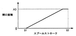
(2)上記(1)において、好ましくは、前記第1流量制御弁は、スプールストロークが増加するにしたがって開口面積が増加し、最大のスプールストロークに達する前に最大開口面積となるように前記開口面積特性が設定され、前記第2流量制御弁は、スプールストロークが中間ストロークになるまでは開口面積はゼロであり、前記中間ストロークで開口し、その後、スプールストロークが増加するにしたがって開口面積が増加し、最大のスプールストロークに達する前に最大開口面積となるように前記開口面積特性が設定される。 (2) In the above (1), preferably, the first flow rate control valve has an opening area that increases as the spool stroke increases and reaches the maximum opening area before reaching the maximum spool stroke. The area characteristic is set, and the second flow rate control valve has an opening area of zero until the spool stroke reaches an intermediate stroke, opens at the intermediate stroke, and then increases as the spool stroke increases. The opening area characteristic is set so that the maximum opening area is reached before the maximum spool stroke is reached.
これにより第1特定アクチュエータの操作装置を操作範囲の中間領域まで操作したときは第1流量制御弁のみが開弁して第2ポンプ装置から第1特定アクチュエータに圧油が供給され、操作装置を中間領域から更に操作したときは第1及び第2流量制御弁の両方が開弁して第1及び第2ポンプ装置からの圧油が第1特定アクチュエータに合流して供給されるようになる。 As a result, when the operating device of the first specific actuator is operated up to the middle region of the operating range, only the first flow control valve is opened and pressure oil is supplied from the second pump device to the first specific actuator, When the operation is further performed from the intermediate region, both the first and second flow control valves are opened, and the pressure oil from the first and second pump devices joins and is supplied to the first specific actuator.
(3)上記(1)において、また好ましくは、前記第2ポンプ装置の容量を制御する第2ポンプ制御装置を更に備え、前記第1ポンプ装置は、前記ロードセンシング制御部と、前記第1ポンプ装置の吐出圧が導かれ、前記第1ポンプ装置の吐出圧と容量の少なくとも一方が増加して、前記第1ポンプ装置の吸収トルクが増加するとき、前記第1ポンプ装置の吸収トルクが第1所定値を超えないように前記第1ポンプ装置の容量を制限制御する第1トルク制御部とを有し、前記第2ポンプ制御装置は、前記第2ポンプ装置の吐出圧が導かれ、前記第2ポンプ装置の吐出圧が増加して、前記第2ポンプ装置の吸収トルクが増加するとき、前記第2ポンプ装置の吸収トルクが第2所定値以下であるときは、前記第2ポンプ装置の容量を最大に維持し、前記第2ポンプ装置の吸収トルクが前記第2所定値まで上昇すると、前記第2ポンプ装置の吸収トルクが第2所定値を超えないように前記第2ポンプ装置の容量を制限制御する第2トルク制御部を有し、前記第1ポンプ制御装置は、前記第2ポンプ装置の吐出圧が導かれ、前記第2ポンプ装置の吐出圧が前記第2トルク制御部の容量制限制御の開始圧力以下であるときは、前記第2ポンプ装置の吐出圧をそのまま出力し、前記第2ポンプ装置の吐出圧が前記第2トルク制御部の容量制限制御の開始圧力よりも上昇すると、前記第2ポンプ装置の吐出圧を前記第2トルク制御部の容量制限制御の開始圧力に減圧して出力する減圧弁と、前記減圧弁の出力圧が導かれ、前記減圧弁の出力圧が高くなるにしたがって前記第1所定値が減少するよう前記第1ポンプ装置の容量を減少させる減トルク制御アクチュエータとを更に有する。 (3) In the above (1), preferably further comprising a second pump control device for controlling a capacity of the second pump device, wherein the first pump device includes the load sensing control unit and the first pump. discharge pressure of the device is guided, at least one of discharge pressure and capacity of the first pump unit is increased, when the absorption torque of the first pump unit is increased, the absorption torque is first of said first pump device A first torque control unit that restricts and controls a capacity of the first pump device so as not to exceed a predetermined value, and the second pump control device receives a discharge pressure of the second pump device, and the discharge pressure of the second pumping device is increased, when the absorption torque of the second pump device is increased, when said absorption torque of the second pump device is equal to or less than the second predetermined value, the capacity of the second pump device Keep the maximum When the absorption torque of the second pump device rises to the second predetermined value, the second torque absorption torque of the second pump means to limit controls the capacity of the second pump device so as not to exceed the second predetermined value The first pump control device is configured such that a discharge pressure of the second pump device is guided, and the discharge pressure of the second pump device is equal to or lower than a start pressure of capacity restriction control of the second torque control unit. In some cases, the discharge pressure of the second pump device is output as it is, and when the discharge pressure of the second pump device rises above the start pressure of the capacity limiting control of the second torque control unit, The pressure reducing valve for reducing the discharge pressure to the start pressure of the capacity limiting control of the second torque control unit and outputting the pressure, and the output pressure of the pressure reducing valve is guided, and the output pressure of the pressure reducing valve increases as the first pressure increases. As the predetermined value decreases Further comprising a torque reduction control actuator to reduce the capacity of serial first pump device.
これにより第2ポンプ装置の吸収トルクが第2所定値まで上昇し、第2トルク制御部の制御により第2所定値に制限されて動作するときだけでなく、第2油圧ポンプの吸収トルクが第2所定値以下で、第2所定値に制限されないときにも、全トルク制御を精度良く行い、原動機の定格出力トルクを有効利用することができる。 As a result, the absorption torque of the second pump device rises to the second predetermined value, and not only when the operation is limited to the second predetermined value by the control of the second torque control unit, but also the absorption torque of the second hydraulic pump is increased. Even when the value is equal to or less than 2 predetermined values and is not limited to the second predetermined value, the total torque control can be performed with high accuracy and the rated output torque of the prime mover can be used effectively.
(4)上記(1)〜3のいずれかにおいて、好ましくは、前記第1アクチュエータは、油圧ショベルのブームを駆動するブームシリンダであり、前記第2特定アクチュエータは、油圧ショベルのアームを駆動するアームシリンダである。 (4) In any one of the above (1) to 3, preferably, the first actuator is a boom cylinder that drives a boom of a hydraulic excavator, and the second specific actuator is an arm that drives an arm of the hydraulic excavator. Cylinder.
これにより負荷圧の差が大きいブーム上げ微操作(負荷圧:高)とアームクラウド操作(負荷圧:低)を同時に行う水平均し動作を行った場合に、低負荷側であるアームシリンダ側の圧力補償弁の絞り圧損による無駄なエネルギー消費を抑えつつ、ブーム上げ微操作(負荷圧:高)とアームクラウド操作(負荷圧:低)でほうき作業を行った場合に、ブームシリンダに供給される圧油の流量を負荷圧によって柔軟に変化させ、良好な操作性を得ることができる。 As a result, when the water leveling operation that simultaneously performs the boom raising fine operation (load pressure: high) and the arm cloud operation (load pressure: low) with a large difference in load pressure is performed, the arm cylinder side, which is the low load side, is operated. It is supplied to the boom cylinder when brooming is performed with a boom raising fine operation (load pressure: high) and an arm cloud operation (load pressure: low) while suppressing wasteful energy consumption due to the pressure compensation valve's throttle pressure loss. The flow rate of the pressure oil can be flexibly changed by the load pressure, and good operability can be obtained.
本発明によれば、特定のアクチュエータ(第1特定アクチュエータ)を含む複合操作で、負荷圧の差が大きく、特定のアクチュエータの操作装置の操作が微操作である場合に、圧力補償弁の無駄な絞り圧損によるエネルギー消費を抑えつつ、特定のアクチュエータに供給される圧油の流量を負荷圧によって柔軟に変化させ、良好な操作性を得ることができる。 According to the present invention, in a complex operation including a specific actuator (first specific actuator), when the load pressure difference is large and the operation of the operation device of the specific actuator is a fine operation, the pressure compensation valve is wasted. While suppressing energy consumption due to throttle pressure loss, the flow rate of the pressure oil supplied to the specific actuator can be flexibly changed by the load pressure, and good operability can be obtained.
以下、本発明の実施の形態を図面に従い説明する。 Hereinafter, embodiments of the present invention will be described with reference to the drawings.
<第1の実施の形態>
〜構成〜
図1は、本発明の第1の実施の形態に係わる油圧ショベル(建設機械)の油圧駆動装置を示す図である。
<First Embodiment>
~Constitution~
FIG. 1 is a diagram showing a hydraulic drive device for a hydraulic excavator (construction machine) according to a first embodiment of the present invention.
図1において、本実施の形態の油圧駆動装置は、原動機(例えばディーゼルエンジン)1と、その原動機1によって駆動され、第1及び第2圧油供給路105,205に圧油を吐出する第1及び第2吐出ポート102a,102bを有するスプリットフロータイプの可変容量型メインポンプ102(第1ポンプ装置)と、原動機1によって駆動され、第3圧油供給路305に圧油を吐出する第3吐出ポート202aを有するシングルフロータイプの可変容量型メインポンプ202(第2ポンプ装置)と、メインポンプ102の第1及び第2吐出ポート102a,102b及びメインポンプ202の第3吐出ポート202aから吐出される圧油により駆動される複数のアクチュエータ3a,3b,3c,3d,3e,3f,3g,3hと、第1〜第3圧油供給路105,205,305に接続され、メインポンプ102の第1及び第2吐出ポート102a,102b及びメインポンプ202の第3吐出ポート202aから複数のアクチュエータ3a〜3hに供給される圧油の流れを制御するコントロールバルブユニット4と、メインポンプ102の第1及び第2吐出ポート102a,102bの吐出流量を制御するためのレギュレータ112(第1ポンプ制御装置)と、メインポンプ202の第3吐出ポート202aの吐出流量を制御するためのレギュレータ212(第2ポンプ制御装置)とを備えている。
In FIG. 1, a hydraulic drive device according to the present embodiment is driven by a prime mover (for example, a diesel engine) 1 and a
複数のアクチュエータ3a,3b,3c,3d,3e,3f,3g,3hのうちアクチュエータ3a,3b,3c,3d,3f,3gはメインポンプ102の第1及び第2吐出ポート102a,102bから吐出された圧油により駆動される複数の第1アクチュエータであり、アクチュエータ3a,3e,3hはメインポンプ202の第3吐出ポート202aから吐出された圧油により駆動される複数の第2アクチュエータであり、アクチュエータ3aは、複数の第1及び第2アクチュエータの両方に含まれる共通のアクチュエータである。
Among the plurality of
コントロールバルブユニット4は、第1及び第2圧油供給路105,205に接続され、メインポンプ102の第1及び第2吐出ポート102a,102bから複数の第1アクチュエータ3a,3b,3c,3d,3f,3gに供給される圧油の流量を制御するクローズドセンタ型の複数の流量制御弁6b,6c,6d,6f,6g,6i,6jと、複数の流量制御弁6b,6c,6d,6f,6g,6i,6jの前後差圧が目標差圧に等しくなるよう複数の流量制御弁6b,6c,6d,6f,6g,6i,6jの前後差圧をそれぞれ制御する複数の圧力補償弁7b,7c,7d,7f,7g,7i、7jと、複数の流量制御弁6b,6c,6d,6f,6g,6i,6jのスプールと一緒にストロークし、各流量制御弁の切り換わりを検出するための複数の操作検出弁8b,8c,8d,8f,8g,8i、8jと、第3圧油供給路305に接続され、メインポンプ202の第3吐出ポート202aから複数の第2アクチュエータ3a,3e,3hに供給される圧油の流量を制御するオープンセンタ型の複数の流量制御弁6a,6e,6hと、第1圧油供給路105に接続され、第1圧油供給路105の圧力を設定圧力以上にならないように制御するメインリリーフ弁114と、第2圧油供給路205に接続され、第2圧油供給路105の圧力を設定圧力以上にならないように制御するメインリリーフ弁214と、第3圧油供給路305に接続され、第3圧油供給路305の圧力を設定圧力以上にならないように制御するメインリリーフ弁314と、第1圧油供給路105に接続され、第1圧油供給路105の圧力が第1吐出ポート102aから吐出される圧油によって駆動されるアクチュエータの最高負荷圧にバネの設定圧力(所定圧力)を加算した圧力(アンロード弁セット圧)よりも高くなると開状態になって第1圧油供給路105の圧油をタンクに戻すアンロード弁115と、第2圧油供給路205に接続され、第2圧油供給路205の圧力が第2吐出ポート102bから吐出される圧油によって駆動されるアクチュエータの最高負荷圧にバネの設定圧力(所定圧力)を加算した圧力(アンロード弁セット圧)よりも高くなると開状態になって第2圧油供給路205の圧油をタンクに戻すアンロード弁215とを備えている。
The control valve unit 4 is connected to the first and second pressure
コントロールバルブユニット4は、また、第1圧油供給路105に接続される流量制御弁6d,6f,6i,6jの負荷ポートに接続され、アクチュエータ3a,3b,3d,3fの最高負荷圧Plmax1を検出するシャトル弁9d,9f,9i,9jを含む第1負荷圧検出回路131と、第2圧油供給路205に接続される流量制御弁6b,6c,6gの負荷ポートに接続され、アクチュエータ3b,3c,3gの最高負荷圧Plmax2を検出するシャトル弁9b,9c,9gを含む第2負荷圧検出回路132と、第1圧油供給路105の圧力(すなわち第1吐出ポート102aの圧力)P1と第1負荷圧検出回路131によって検出された最高負荷圧Plmax1(第1圧油供給路105に接続されるアクチュエータ3a,3b,3d,3fの最高負荷圧)との差(LS差圧)を絶対圧Pls1として出力する差圧減圧弁111と、第2圧油供給路205の圧力(すなわち第2吐出ポート102bの圧力)P2と第2負荷圧検出回路132によって検出された最高負荷圧Plmax2(第2圧油供給路205に接続されるアクチュエータ3b,3c,3gの最高負荷圧)との差(LS差圧)を絶対圧Pls2として出力する差圧減圧弁211とを備えている。以下において、差圧減圧弁111,211が出力する絶対圧Pls1,Pls2を、適宜、LS差圧Pls1,Pls2という。
The control valve unit 4 is also connected to the load ports of the flow control valves 6d, 6f, 6i, 6j connected to the first pressure
前述したアンロード弁115には、第1吐出ポート102aから吐出される圧油によって駆動されるアクチュエータの最高負荷圧として第1負荷圧検出回路131によって検出された最高負荷圧Plmax1が導かれ、前述したアンロード弁215には、第2吐出ポート102bから吐出される圧油によって駆動されるアクチュエータの最高負荷圧として第2負荷圧検出回路132によって検出された最高負荷圧Plmax2が導かれる。
The above-described unload valve 115 receives the maximum load pressure Plmax1 detected by the first load
また、差圧減圧弁111が出力するLS差圧Pls1は、第1圧油供給路105に接続された圧力補償弁7d,7f,7i,7jとメインポンプ102のレギュレータ112に導かれ、差圧減圧弁211が出力するLS差圧Pls2は、第2圧油供給路205に接続された圧力補償弁7b,7c,7gとメインポンプ102のレギュレータ112に導かれる。
The LS differential pressure Pls1 output from the differential
ここで、アクチュエータ3aは、流量制御弁6i及び圧力補償弁7iと第1圧油供給路105を介して第1吐出ポート102aに接続され、かつ流量制御弁6aと第3圧油供給路305を介して第3吐出ポート202aに接続されている。アクチュエータ3aは、例えば油圧ショベルのブームを駆動するブームシリンダ(第1特定アクチュエータ)であり、流量制御弁6aはブームシリンダ3aのメイン駆動用(第1流量制御弁)であり、流量制御弁6iはブームシリンダ3aのアシスト駆動用(第2流量制御弁)である。アクチュエータ3bは、流量制御弁6j及び圧力補償弁7jと第1圧油供給路105を介して第1吐出ポート102aに接続され、かつ流量制御弁6b及び圧力補償弁7bと第2圧油供給路205を介して第2吐出ポート102bに接続されている。アクチュエータ3bは、例えば油圧ショベルのアームを駆動するアームシリンダ(第2特定アクチュエータ)であり、流量制御弁6bはアームシリンダ3bのメイン駆動用であり、流量制御弁6jはアームシリンダ3bのアシスト駆動用である。
Here, the
アクチュエータ3d,3fはそれぞれ流量制御弁6d,6f及び圧力補償弁7d,7fと第1圧油供給路105を介して第1吐出ポート102aに接続され、アクチュエータ3c,3gはそれぞれ流量制御弁6c,6g及び圧力補償弁7c,7gと第2圧油供給路205を介して第2吐出ポート102bに接続されている。アクチュエータ3d,3fは、それぞれ、例えば油圧ショベルのバケットを駆動するバケットシリンダ、下部走行体の左側履帯を駆動する左走行モータである。アクチュエータ3c,3gは、それぞれ、例えば油圧ショベルの上部旋回体を駆動する旋回モータ、下部走行体の右側履帯を駆動する右走行モータである。アクチュエータ3e,3hはそれぞれ流量制御弁6e,6hと第3圧油供給路305を介して第3吐出ポート202aに接続されている。アクチュエータ3e,3hは、それぞれ、例えば油圧ショベルのスイングポストを駆動するスイングシリンダ、ブレードを駆動するブレードシリンダである。
The
ブームシリンダ3a及びアームシリンダ3bは、他のアクチュエータよりも最大の要求流量が大きいアクチュエータである。また、アームシリンダ3b(第2特定アクチュエータ)はブームシリンダ3a(第1アクチュエータ)と複合操作で使用される頻度の高いアクチュエータである。
The
図2Aは、アクチュエータ3c〜3h(ブームシリンダ3a及びアームシリンダ3b以外のアクチュエータ)の流量制御弁6c〜6h(クローズドセンタ型)のそれぞれのメータイン通路の開口面積特性を示す図である。これらの流量制御弁は、スプールストロークが不感帯0−S1を超えて増加するにしたがってメータイン通路の開口面積が増加し、最大のスプールストロークS3の直前で最大開口面積A3となるように開口面積特性が設定されている。最大開口面積A3は、アクチュエータの種類に応じてそれぞれ固有の大きさを持つ。
FIG. 2A is a diagram illustrating the opening area characteristics of the meter-in passages of the
図2Bは、アームシリンダ3b(第2特定アクチュエータ)の流量制御弁6b,6j(クローズドセンタ型)のメータイン通路の開口面積特性を示す図であり、図2Bの上側は、流量制御弁6b,6jの開口面積特性を個別に示している。
FIG. 2B is a diagram showing the opening area characteristics of the meter-in passages of the flow control valves 6b and 6j (closed center type) of the
アームシリンダ3bのメイン駆動用の流量制御弁6bは、スプールストロークが不感帯0−S1を超えて増加するにしたがってメータイン通路の開口面積が増加し、中間ストロークS2で最大開口面積A1となり、その後、最大のスプールストロークS3まで最大開口面積A1が維持されるように開口面積特性が設定されている。
In the flow control valve 6b for main drive of the
アームシリンダ3bのアシスト駆動用の流量制御弁6jは、スプールストロークが中間ストロークS2になるまではメータイン通路の開口面積はゼロであり、スプールストロークが中間ストロークS2を超えて増加するにしたがって開口面積が増加し、最大のスプールストロークS3の直前で最大開口面積A2となるように開口面積特性が設定されている。
The flow control valve 6j for assist driving of the
図2Bの下側は、アームシリンダ3bの流量制御弁6b,6jのメータイン通路の合成開口面積特性を示す図である。
The lower side of FIG. 2B is a diagram showing a composite opening area characteristic of the meter-in passage of the flow control valves 6b and 6j of the
アームシリンダ3bの流量制御弁6b,6jのメータイン通路は、それぞれが上記のような開口面積特性を有する結果、スプールストロークが不感帯0−S1を超えて増加するにしたがって開口面積が増加し、最大のスプールストロークS3の直前で最大開口面積A1+A2となるような合成開口面積特性となる。
The meter-in passages of the flow control valves 6b and 6j of the
ここで、図2Aに示すアクチュエータ3c〜3hの流量制御弁6c,6d,6e,6f,6g,6hの最大開口面積A3とアームシリンダ3bの流量制御弁6b,6jの合成した最大開口面積A1+A2は、A1+A2>A3の関係にある。
Here, the maximum opening area A3 of the
流量制御弁6c〜6h及びアームシリンダ3bの流量制御弁6b,6jは、それぞれ、圧力補償弁7c〜7h及び圧力補償弁7b,7jによって前後差圧が制御されている。このため流量制御弁6c〜6h及び6b,6jの通過流量はそれぞれのメータイン通路の開口面積に比例して増加し、流量制御弁6c〜6h及び6b,6jの流量特性は図2A及び図2Bと同様な特性となる。
The flow
図5Aは、ブームシリンダ3a(第1特定アクチュエータ)のメイン駆動用の流量制御弁6a(オープンセンタ型−第1流量制御弁)のメータイン通路、メータアウト通路及びブリードオフ通路(センタバイパス通路)の開口面積特性を示す図である。
FIG. 5A shows the meter-in passage, meter-out passage, and bleed-off passage (center bypass passage) of the main flow control valve 6a (open center type-first flow control valve) for the
ブームシリンダ3aのメイン駆動用の流量制御弁6aは、スプールストロークが不感帯0−S1を超えて増加するにしたがって開口面積が増加し、最大のスプールストロークS3に達する前にそれぞれ最大開口面積A4,A5となるようにメータイン通路及びメータアウト通路の開口面積特性が設定されている。ただし、メータイン通路の開口面積特性は最大開口面積A4がメータアウト通路の開口面積特性の最大開口面積A5よりも大きくなるように設定され、かつスプールストロークが中間ストロークS2を超えて増加するときは、それまでよりも開口面積の増加割合が大きくなるように設定されている。また、ブームシリンダ3aのメイン駆動用の流量制御弁6aは、スプールストロークが0であるとき最大開口面積A4であり、スプールストロークがゼロから増加するにしたがって開口面積が減少し、中間ストロークS2で開口面積がゼロになるようにブリードオフ通路の開口面積特性が設定されている。ただし、ブリードオフ通路の開口面積特性はスプールストロークが不感帯0−S1を超えて増加するときは、それまでよりも開口面積の減少割合が小さくなるように設定されている。
The flow control valve 6a for main drive of the
図5Bは、ブームシリンダ3aのアシスト駆動用の流量制御弁6i(クローズドセンタ型−第2流量制御弁)のメータイン通路の開口面積特性を示す図である。
FIG. 5B is a diagram illustrating an opening area characteristic of the meter-in passage of the flow control valve 6i for assist driving of the
ブームシリンダ3aのアシスト駆動用の流量制御弁6iは、スプールストロークが中間ストロークS2になるまではメータイン通路の開口面積はゼロであり、中間ストロークS2でメータイン通路が開口し、その後スプールストロークが増加するにしたがってメータイン通路の開口面積が増加し、最大のスプールストロークS3の直前で最大開口面積A6となるように開口面積特性が設定されている。
The flow control valve 6i for assist drive of the
ここで、図5A、図5Bの下側に示すように、流量制御弁6a,6iのスプールストロークはブーム用の操作装置123(後述−図7参照)が生成する操作パイロット圧が上昇するに従って増加する。中間ストロークS2はブーム用の操作装置123の操作範囲の中間領域で生成される操作パイロット圧に対応する。
Here, as shown on the lower side of FIGS. 5A and 5B, the spool stroke of the flow rate control valves 6a and 6i increases as the operating pilot pressure generated by the boom operating device 123 (described later-see FIG. 7) increases. To do. The intermediate stroke S2 corresponds to the operation pilot pressure generated in the intermediate region of the operation range of the
このようにブーム用の操作装置123を操作範囲の中間領域まで操作したときは流量制御弁6a(第1流量制御弁)のみが開弁してメインポンプ202(第2ポンプ装置)からブームシリンダ3a(第1特定アクチュエータ)に圧油が供給され、操作装置123を前記中間領域から更に操作したときは流量制御弁6a,6i(第1及び第2流量制御弁)の両方が開弁してメインポンプ102,202(第1及び第2ポンプ装置)からの圧油がブームシリンダ3a(第1特定アクチュエータ)に合流して供給されるように流量制御弁6a,6i(第1及び第2流量制御弁)の開口面積特性が設定されている。
Thus, when the
ここで、図5A及び図5Bでは、流量制御弁6aのブリードオフ通路が閉じるスプールストロークと流量制御弁6iのメータイン通路が開くスプールストロークを同じ中間ストロークS2としたが、僅かであれば両者の中間ストロークは異なっていてもよい。例えば流量制御弁6aのブリードオフ通路が閉じる直前に流量制御弁6iのメータイン通路が開くようにしてもよく、これによりスムーズな流量増加が可能となる。 5A and 5B, the spool stroke for closing the bleed-off passage of the flow control valve 6a and the spool stroke for opening the meter-in passage of the flow control valve 6i are the same intermediate stroke S2. The stroke may be different. For example, the meter-in passage of the flow control valve 6i may be opened immediately before the bleed-off passage of the flow control valve 6a is closed, thereby enabling a smooth increase in the flow rate.
図5Cはブームシリンダ3aの流量制御弁6a,6iのメータインの流量特性を示す図であり、図5Cの上側は、流量制御弁6a,6iのメータインの流量特性を個別に示している。
FIG. 5C is a diagram showing the meter-in flow characteristics of the flow control valves 6a and 6i of the
メイン駆動用の流量制御弁6a(第1流量制御弁)は、スプールストロークが中間ストロークS2に達するまではメータイン通路とブリードオフ通路の両方が開いており、その間は、スプールストロークが不感帯0−S1を超えて増加するにしたがって供給流量が増加しかつ負荷圧が増加するに従って供給流量は減少する。スプールストロークが中間ストロークS2に達するとブリードオフ通路の開口面積がゼロになり、メインポンプ202の吐出油の全量Q1がブームシリンダ3aに供給される。
In the main drive flow control valve 6a (first flow control valve), both the meter-in passage and the bleed-off passage are open until the spool stroke reaches the intermediate stroke S2, during which the spool stroke is in the dead zone 0-S1. The supply flow rate increases as the pressure increases over and the supply flow rate decreases as the load pressure increases. When the spool stroke reaches the intermediate stroke S2, the opening area of the bleed-off passage becomes zero, and the total amount Q1 of the discharge oil from the
アシスト駆動用の流量制御弁6i(第2流量制御弁)は圧力補償弁7bによって前後差圧が制御されている。このため流量制御弁6iの通過流量はメータイン通路の開口面積に比例して増加し、流量制御弁6iの流量特性は、図5Bと同様な特性となる。すなわち、中間ストロークS2でブームシリンダ3aに圧油が供給され始め、その後スプールストロークが増加するにしたがって供給流量が増加し、最大のスプールストロークS3の直前で最大供給流量Q2となる。
The flow rate control valve 6i (second flow rate control valve) for assist driving has a differential pressure controlled by a pressure compensation valve 7b. For this reason, the passage flow rate of the flow rate control valve 6i increases in proportion to the opening area of the meter-in passage, and the flow rate characteristic of the flow rate control valve 6i is the same as that in FIG. 5B. That is, pressure oil starts to be supplied to the
図5Cの下側は、ブームシリンダ3aの流量制御弁6a,6iのメータインの合成流量特性を示す図である。
The lower side of FIG. 5C is a diagram showing the combined flow characteristics of meter-in of the flow control valves 6a and 6i of the
ブームシリンダ3aの流量制御弁6a,6iの流量特性が、それぞれ上記のように設定されている結果、スプールストロークが中間ストロークS2に達するまでは、スプールストロークが不感帯0−S1を超えて増加するにしたがって供給流量が増加しかつ負荷圧が増加するに従って供給流量は減少する。スプールストロークが中間ストロークS2に達した後は、スプールストロークが増加するにしたがって供給流量が増加し、最大のスプールストロークS3の直前で最大供給流量Q1+Q2となる。
As a result of the flow rate characteristics of the flow control valves 6a and 6i of the
図1に戻り、コントロールバルブユニット4は、上流側が絞り43を介してパイロット圧油供給路31b(後述)に接続され下流側が操作検出弁8b,8c,8d,8f,8g,8i,8jを介してタンクに接続された走行複合操作検出油路53と、この走行複合操作検出油路53によって生成される操作検出圧に基づいて切り換わる第1切換弁40,第2切換弁146及び第3切換弁246とを更に備えている。
Returning to FIG. 1, the control valve unit 4 has an upstream side connected to a pilot pressure oil supply passage 31b (described later) via a
走行複合操作検出油路53は、左走行モータであるアクチュエータ3f(以下適宜左走行モータ3fという)及び/又は右走行モータであるアクチュエータ3g(以下適宜右走行モータ3gという)と、第1圧油供給路105と第2圧油供給路205に接続される左右走行モータ以外のアクチュエータ3a,3b,3c,3dの少なくとも1つとを同時で駆動する走行複合操作でないときは、少なくとも操作検出弁8a,8b,8c,8d,8f,8g,8i,8jのいずれかを介してタンクに連通することで油路53の圧力がタンク圧となり、当該走行複合操作時は、操作検出弁8f,8gと、操作検出弁8a,8b,8c,8d,8i,8jのいずれかがそれぞれ対応する流量制御弁と一緒にストロークしてタンクとの連通が遮断されることで、油路53に操作検出圧(操作検出信号)を生成する。
The travel composite operation
第1切換弁40は、走行複合操作でないときは、図示下側の第1位置(遮断位置)にあって、第1圧油供給路105と第2圧油供給路205の連通を遮断し、走行複合操作時に、走行複合操作検出油路53にて生成された操作検出圧によって図示上側の第2位置(連通位置)に切り替わって、第1圧油供給路105と第2圧油供給路205を連通させる。
When the first switching valve 40 is not a travel combined operation, the first switching valve 40 is in a first position (blocking position) on the lower side in the figure, and blocks communication between the first pressure
第2切換弁146は、走行複合操作でないときは、図示下側の第1位置にあって、タンク圧を第2負荷圧検出回路132の最下流のシャトル弁9gに導き、走行複合操作時に、走行複合操作検出油路53にて生成された操作検出圧によって図示上側の第2位置に切り替わって、第1負荷圧検出回路131によって検出された最高負荷圧Plmax1(第1圧油供給路105に接続されるアクチュエータ3a,3b,3d,3fの最高負荷圧)を第2負荷圧検出回路132の最下流のシャトル弁9gに導く。
The
第3切換弁246は、走行複合操作でないときは、図示下側の第1位置にあって、タンク圧を第1負荷圧検出回路131の最下流のシャトル弁9fに導き、走行複合操作時に、走行複合操作検出油路53にて生成された操作検出圧によって図示上側の第2位置に切り替わって、第2負荷圧検出回路132によって検出された最高負荷圧Plmax2(第2圧油供給路205に接続されるアクチュエータ3b,3c,3gの最高負荷圧)を第1負荷圧検出回路131の最下流のシャトル弁9fに導く。
The
第1切換弁40、第2切換弁146及び第3切換弁246を走行複合操作検出油路53によって生成される操作検出圧に基づいて上記のように切り換えることで、走行複合操作でないとき(走行単独操作時)は、左走行モータ3fはスプリットフロータイプのメインポンプ102の第1吐出ポート102aから吐出される圧油で駆動され、右走行モータ3gはスプリットフロータイプのメインポンプ102の第2吐出ポート102bから吐出される圧油で駆動される。走行複合操作時は、第1切換弁40が第2位置に切り換わって第1圧油供給路105と第2圧油供給路205が連通し、第1及び第2吐出ポート102a,102bは1つのポンプとして機能し、メインポンプ102の第1吐出ポート102aの吐出油と第2吐出ポート102bの吐出油は合流し、その合流した圧油で左走行モータ3fと右走行モータ3gが駆動される。
By switching the first switching valve 40, the
また、図1において、本実施の形態における油圧駆動装置は、原動機1によって駆動される固定容量型のパイロットポンプ30と、パイロットポンプ30の圧油供給路31aに接続され、パイロットポンプ30の吐出流量を絶対圧Pgrとして検出する原動機回転数検出弁13と、原動機回転数検出弁13の下流側のパイロット圧油供給路31bに接続され、パイロット圧油供給路31bに一定のパイロット一次圧Ppilotを生成するパイロットリリーフバルブ32と、パイロット圧油供給路31bに接続され、ゲートロックレバー24により下流側のパイロット圧油供給路31cをパイロット圧油供給路31bに接続するかタンクに接続するかを切り替えるゲートロック弁100と、ゲートロック弁100の下流側のパイロット圧油供給路31cに接続され、後述する複数の流量制御弁6a,6b,6c,6d,6e,6f,6g,6hを制御するための操作パイロット圧を生成する複数のリモコン弁(減圧弁)を有する複数の操作装置122,123,124a,124b(図7)とを備えている。
In FIG. 1, the hydraulic drive apparatus according to the present embodiment is connected to a fixed
原動機回転数検出弁13は、パイロットポンプ30の圧油供給路31aとパイロット圧油供給路31bとの間に接続された流量検出弁50と、その流量検出弁50の前後差圧を絶対圧Pgrとして出力する差圧減圧弁51とを有している。
The prime mover rotational
流量検出弁50は通過流量(パイロットポンプ30の吐出流量)が増大するにしたがって開口面積を大きくする可変絞り部50aを有している。パイロットポンプ30の吐出油は流量検出弁50の可変絞り部50aを通過してパイロット圧油供給路31b側へと流れる。このとき、流量検出弁50の可変絞り部50aには通過流量が増加するにしたがって大きくなる前後差圧が発生し、差圧減圧弁51はその前後差圧を絶対圧Pgrとして出力する。パイロットポンプ30の吐出流量は原動機1の回転数によって変化するため、可変絞り部50aの前後差圧を検出することにより、パイロットポンプ30の吐出流量を検出することができ、原動機1の回転数を検出することができる。原動機回転数検出弁13(差圧減圧弁51)が出力する絶対圧Pgrは目標LS差圧としてレギュレータ112に導かれる。以下において、差圧減圧弁51が出力する絶対圧Pgrを、適宜、出力圧Pgr或いは目標LS差圧Pgrという。
The flow
レギュレータ112(第1ポンプ制御装置)は、差圧減圧弁111が出力するLS差圧Pls1と差圧減圧弁211が出力するLS差圧Pls2の低圧側を選択する低圧選択弁112aと、低圧選択されたLS差圧Pls12と目標LS差圧である原動機回転数検出弁13の出力圧Pgrとが導かれ、LS差圧Pls12が目標LS差圧Pgrよりも小さくなるにしたがって低くなるようロードセンシング駆動圧力(以下LS駆動圧力という)を変化させるLS制御弁112bと、LS駆動圧力が導かれ、LS駆動圧力が低くなるにしたがってメインポンプ102の傾転角(容量)を増加させ吐出流量が増加するようメインポンプ102の傾転角を制御するLS制御ピストン112cと、メインポンプ102の第1及び第2吐出ポート102a,102bのそれぞれの圧力が導かれ、それらの圧力の上昇時にメインポンプ102の斜板の傾転角を減少させ、吸収トルクが減少するようメインポンプ102の傾転角を制御するトルク制御(馬力制御)ピストン112e,112d(第1トルク制御アクチュエータ)と、最大トルクT12max(図3A参照)を設定する第1付勢手段であるバネ112uとを備えている。
The regulator 112 (first pump control device) includes a low
また、レギュレータ112(第1ポンプ制御装置)は、メインポンプ202の第3吐出ポート202aの吐出圧(第3圧油供給路305の圧力)が導かれ、その圧力がバネ112tのセット圧(容量制限制御の開始圧力)以下である場合は、メインポンプ202の第3吐出ポート202aの吐出圧をそのまま出力し、メインポンプ202の第3吐出ポート202aの吐出圧がバネ112tのセット圧(容量制限制御の開始圧力)よりも上昇すると、メインポンプ202の第3吐出ポート202aの吐出圧をバネ112tのセット圧(容量制限制御の開始圧力)に減圧して出力する減圧弁112gと、減圧弁112gの出力圧が導かれ、減圧弁112gの出力圧が高くなるにしたがってメインポンプ102の最大トルク(第1所定値)が減少するようメインポンプ2の容量を減少させる減トルク制御ピストン112fとを備えている。
The regulator 112 (first pump control device) is guided by the discharge pressure of the third discharge port 202a of the main pump 202 (pressure of the third pressure oil supply passage 305), and the pressure is set pressure (capacity) of the
低圧選択弁112a、LS制御弁112b及びLS制御ピストン112cは、メインポンプ102の吐出圧(第1及び第2吐出ポート102a,102bの高圧側の吐出圧)が、メインポンプ102から吐出される圧油によって駆動されるアクチュエータの最高負荷圧(最高負荷圧Plmax1と最高負荷圧Plmax2の高圧側の圧力)より目標差圧(目標LS差圧Pgr)だけ高くなるようメインポンプ102の容量を制御する第1ロードセンシング制御部を構成する。
The low
トルク制御ピストン112d,112e及びバネ112uと減圧弁112g及び減トルク制御ピストン112fは、メインポンプ102の第1及び第2吐出ポート102a,102bのそれぞれの吐出圧(メインポンプ102の吐出圧)とメインポンプ102の容量の少なくとも一方が増加して、メインポンプ102の吸収トルクが増加するとき、メインポンプ102の吸収トルクが最大トルク(第1所定値)を超えないようにメインポンプ102の容量を制限制御する第1トルク制御部を構成する。ここで、メインポンプ102の最大トルク(第1所定値)は可変であり、T12max〜T12max−T3maxの範囲で変化する(後述)。
The torque control pistons 112d and 112e, the spring 112u, the pressure reducing valve 112g, and the torque reduction control piston 112f are respectively connected to the discharge pressure (discharge pressure of the main pump 102) of the first and
第1ロードセンシング制御部(低圧選択弁112a、LS制御弁112b及びLS制御ピストン112c)は、メインポンプ102が第1トルク制御部によるトルク制御の制限を受けていないときに機能し、ロードセンシング制御によりメインポンプ102の容量を制御する。
The first load sensing control unit (the low
レギュレータ212(第2ポンプ制御装置)は、メインポンプ202の吐出圧P3が導かれ、その圧力の上昇時にメインポンプ202の斜板の傾転角を減少させ、吸収トルクが減少するようメインポンプ202の傾転角を制御するトルク制御(馬力制御)ピストン212d(第2トルク制御アクチュエータ)と、最大トルクT3max(図3B参照)を設定する第2付勢手段であるバネ212eとを備えている。
The regulator 212 (second pump control device) is guided by the discharge pressure P3 of the
トルク制御ピストン212dとバネ212eは、メインポンプ202の吐出圧P3が増加して、メインポンプ202の吸収トルクが増加するとき、メインポンプ202の吸収トルクが最大トルクT3max(第2所定値)以下であるときは、メインポンプ202の容量を最大q3maxに維持し、メインポンプ202の吸収トルクがT3max(第2所定値)まで上昇すると、メインポンプ202の吸収トルクがT3max(第2所定値)を超えないようにメインポンプ202の容量を制限制御する第2トルク制御部を構成する。
When the discharge pressure P3 of the
減圧弁112gのバネ112tのセット圧は、メインポンプ202の吸収トルクが最大トルクT3max(第2所定値)に達すると、メインポンプ202の第3吐出ポート202aの吐出圧をT3max(第2所定値)に対応する圧力に減圧して出力するよう、バネ212のセット圧である容量制限制御の開始圧力(以下トルク制御開始圧力という)P3c(図4A及び図4B)に等しく設定されている。以下、適宜、減圧弁112gのバネ112tのセット圧を減圧弁112gのセット圧という。
When the absorption torque of the
図3は、第1トルク制御部(トルク制御ピストン112d,112e、バネ112u、減圧弁112g及び減トルク制御ピストン112f)により得られるトルク制御特性(PQ特性)と減トルク制御ピストン112fによる減トルク制御の効果を示す図である。図3中、横軸のP12は、第1及び第2圧油供給路105,205の圧力P1,P2の合計P1+P2(メインポンプ102の吐出圧)であり、縦軸のq12はメインポンプ102の斜板の傾転角(容量)であり、q12maxはメインポンプ102の構造で決まる最大傾転角である。メインポンプ102の吸収トルクは、メインポンプ102の吐出圧P12(P1+P2)と傾転角q12との積で表される。また、横軸のP12maxはメインリリーフ弁114,214の設定圧力によって得られるメインポンプ102の最大吐出圧力である。
FIG. 3 shows torque control characteristics (PQ characteristics) obtained by the first torque control unit (torque control pistons 112d and 112e, spring 112u, pressure reducing valve 112g and torque reduction control piston 112f) and torque reduction control by the torque reduction control piston 112f. It is a figure which shows the effect of. In FIG. 3, P12 on the horizontal axis is the total P1 + P2 (discharge pressure of the main pump 102) of the pressures P1 and P2 of the first and second pressure
図3において、502は、バネ112uによって設定されたメインポンプ102の最大吸収トルクT12maxを示すトルク一定曲線である。メインポンプ202に係わるアクチュエータが動作しておらず、減トルク制御ピストン112fに導かれるメインポンプ202の吐出圧がタンク圧であるとき、メインポンプ102の吐出圧或いは傾転角が増加してメインポンプ102の吸収トルクが増加し最大トルクT12maxに達すると、メインポンプ102の吸収トルクがそれ以上増加しないようメインポンプ102の傾転角はレギュレータ112のトルク制御ピストン112d,112eによって制限制御される。例えば、メインポンプ102が最大傾転角q12maxにある状態で、メインポンプ102の吐出圧がトルク制御開始圧力を超えて上昇すると、メインポンプ102の傾転角q12はトルク一定曲線502に沿って減少する。また、メインポンプ102の傾転角がトルク一定曲線502上のいずれかにある状態でメインポンプ102の傾転角q12が増加するよう制御される場合は、メインポンプ102の傾転角q12はトルク一定曲線502上の傾転角に保持されるよう制限制御される。図3中、TEは原動機1の定格出力トルクTerateを示すトルク一定曲線であり、最大トルクT12maxはTerateよりも小さい値に設定されている。このように最大トルクT12maxを設定し、メインポンプ102の吸収トルクが最大トルクT12maxを超えないように制限することで、原動機1の定格出力トルクTerateを最大限有効に利用しつつ、メインポンプ102がアクチュエータを駆動するときの原動機1の停止(エンジンストール)を防止することができる。
In FIG. 3,
図4Aは、第2トルク制御部(トルク制御ピストン212dとバネ212e)により得られるトルク制御特性をPQ特性で示す図であり、図4Bは同トルク制御特性を、縦軸をポンプトルクに置き換えて示す図である。図4A及び図4B中、横軸のP3はメインポンプ202の吐出圧であり、縦軸のq3,T3はそれぞれメインポンプ202の斜板の傾転角(容量)及び吸収トルクであり、q3maxはメインポンプ202の構造で決まる最大傾転角である。メインポンプ202の吸収トルクは、メインポンプ202の吐出圧P3と傾転角q3との積で表される。また、横軸のP3maxはメインリリーフ弁314の設定圧力によって得られるメインポンプ202の最大吐出圧力である。
FIG. 4A is a diagram showing a torque control characteristic obtained by the second torque control unit (torque control piston 212d and spring 212e) as a PQ characteristic, and FIG. 4B is a diagram in which the vertical axis is replaced with a pump torque. FIG. 4A and 4B, P3 on the horizontal axis is the discharge pressure of the
図4Aにおいて、602は、バネ212eによって設定されたメインポンプ202の最大吸収トルクT3maxを示すトルク一定曲線である。メインポンプ202の第3吐出ポート202aの吐出圧がバネ112uのセット圧であるトルク制御開始圧力P3c(図4A及び図4B)以下であるときは、メインポンプ202の容量は最大q3maxで一定であり、図4Bに示すように、メインポンプ202の吸収トルクは吐出圧が上昇するに従って直線比例的に増加する。メインポンプ202の第3吐出ポート202aの吐出圧がトルク制御開始圧力P3cまで上昇すると、メインポンプ202の吸収トルクが最大トルクT3maxに達し、図3のレギュレータ112の場合と同様、メインポンプ202の吸収トルクがそれ以上増加しないようメインポンプ202の傾転角はレギュレータ212のトルク制御ピストン212dによって制限制御される。
4A,
また、メインポンプ202の吸収トルク(傾転角)が上記のように制御されるときメインポンプ202の吐出圧(第3吐出ポート202aの圧力)は減圧弁112gを介して減トルク制御ピストン112fに導かれ、バネ212eのセット圧である最大トルクT12max(第1所定値)を減少させる減トルク制御を行う。
When the absorption torque (tilt angle) of the
すなわち、メインポンプ202の第3吐出ポート202aの吐出圧がトルク制御開始圧力P3c(図4A及び図4B)以下であるとき、減圧弁112gの出力圧は、メインポンプ202の吐出圧が上昇するに従って図4Bのメインポンプ202の吸収トルクと同じように増加し、メインポンプ202の第3吐出ポート202aの吐出圧がトルク制御開始圧力P3cに達すると、メインポンプ202の吐出圧が上昇するに従って図4Bのメインポンプ202の吸収トルクと同様に一定となる。また、その一定の圧力はメインポンプ202の最大トルクT3max(第2所定値)に対応している。このように減圧弁112gはメインポンプ202の吸収トルクを模擬した圧力を出力し、この圧力が減トルク制御ピストン112fに導かれてメインポンプ102の最大トルク(第1所定値)が減少するよう制御される。
That is, when the discharge pressure of the third discharge port 202a of the
図3において、矢印は、減圧弁112g及び減トルク制御ピストン112fの減トルク制御の効果を示している。メインポンプ202の吐出圧が上昇するとき、メインポンプ202の吸収トルクがT3max(第2所定値)以下であるときは、減圧弁112gはメインポンプ202の第3吐出ポート202aの吐出圧をそのまま出力し、減トルク制御ピストン112fは、図3のトルク一定曲線504に示すように、メインポンプ102の最大トルクをトルク一定曲線502のT12maxからメインポンプ202の吸収トルク分(T3)だけ減少させる。また、メインポンプ202の吐出圧が上昇し、メインポンプ202の吸収トルクがT3max(第2所定値)に達すると、減圧弁112gはメインポンプ202の第3吐出ポート202aの吐出圧をT3max(第2所定値)に対応する圧力(トルク制御開始圧力P3c)に減圧して出力し、減トルク制御ピストン112fは、図3のトルク一定曲線503に示すように、メインポンプ102の最大トルク(第1所定値)を図3のトルク一定曲線502のT12maxからメインポンプ202の吸収トルク(最大トルク)T3max分だけ減少させる。
In FIG. 3, the arrow indicates the effect of the torque reduction control of the pressure reducing valve 112g and the torque reduction control piston 112f. When the discharge pressure of the
これによりメインポンプ102に係わるアクチュエータとメインポンプ202に係わるアクチュエータを同時に駆動する複合操作時或いはメインポンプ102とメインポンプ202の両方に係わるアクチュエータ(ブームシリンダ3a)を駆動する操作時においても、メインポンプ102の吸収トルクとメインポンプ202の吸収トルクの合計が最大トルクT12maxを超えないように制御され(全トルク制御或いは全馬力制御−以下全トルク制御という)、原動機1の停止(エンジンストール)を防止することができる。また、減圧弁112gはメインポンプ202の吸収トルクを模擬した圧力を出力し、この圧力を減トルク制御ピストン112fに導いてメインポンプ102の最大トルクを減少させるため、メインポンプ202が第2トルク制御部の制限を受け最大トルクT3maxで動作するときだけでなく、メインポンプ202が第2トルク制御部の制限を受けないときにも、全トルク制御を精度良く行い、原動機の定格出力トルクTerateを有効利用することができる。
As a result, the main pump can be used in the combined operation of simultaneously driving the actuator related to the
〜油圧ショベル〜
図7は、上述した油圧駆動装置が搭載される油圧ショベルの外観を示す図である。
~ Hydraulic excavator ~
FIG. 7 is a view showing an appearance of a hydraulic excavator on which the above-described hydraulic drive device is mounted.
図7において、作業機械としてよく知られている油圧ショベルは、下部走行体101と、上部旋回体109と、スイング式のフロント作業機104を備え、フロント作業機104は、ブーム104a、アーム104b、バケット104cから構成されている。上部旋回体109は下部走行体101に対して旋回モータ3cによって旋回可能である。上部旋回体109の前部にはスイングポスト103が取り付けられ、このスイングポスト103にフロント作業機104が上下動可能に取り付けられている。スイングポスト103はスイングシリンダ3eの伸縮により上部旋回体109に対して水平方向に回動可能であり、フロント作業機104のブーム104a、アーム104b、バケット104cはブームシリンダ3a,アームシリンダ3b,バケットシリンダ3dの伸縮により上下方向に回動可能である。下部走行体101の中央フレームには、ブレードシリンダ3h(図1参照)の伸縮により上下動作を行うブレード106が取り付けられている。下部走行体101は、走行モータ3f,3gの回転により左右の履帯101a,101b(図7では左側のみ図示)を駆動することによって走行を行う。
In FIG. 7, a hydraulic excavator well known as a work machine includes a
上部旋回体109にはキャノピータイプの運転室108が設置され、運転室108内には、運転席121、フロント/旋回用の左右の操作装置122,123(図7では左側のみ図示)、走行用の操作装置124a,124b(図7では左側のみ図示)、図示しないスイング用の操作装置及びブレード用の操作装置、ゲートロックレバー24等が設けられている。操作装置122,123の操作レバーは中立位置から十字方向を基準とした任意の方向に操作可能であり、左側の操作装置122の操作レバーを前後方向に操作するとき、操作装置122は旋回用の操作装置として機能し、同操作装置122の操作レバーを左右方向に操作するとき、操作装置122はアーム用の操作装置として機能し、右側の操作装置123の操作レバーを前後方向に操作するとき、操作装置123はブーム用の操作装置として機能し、同操作装置123の操作レバーを左右方向に操作するとき、操作装置123はバケット用の操作装置として機能する。
The
〜動作〜
次に、本実施の形態の動作を説明する。
~ Operation ~
Next, the operation of the present embodiment will be described.
まず、原動機1によって駆動される固定容量型のパイロットポンプ30から吐出された圧油は、圧油供給路31aに供給される。圧油供給路31aには原動機回転数検出弁13が接続されており、原動機回転数検出弁13は流量検出弁50と差圧減圧弁51によりパイロットポンプ30の吐出流量に応じた流量検出弁50の前後差圧を絶対圧Pgr(目標LS差圧)として出力する。原動機回転数検出弁13の下流にはパイロットリリーフバルブ32が接続されており、パイロット圧油供給路31bに一定の圧力(パイロット一次圧Ppilot)を生成している。
First, the pressure oil discharged from the fixed
(a)全ての操作レバーが中立の場合
全ての操作装置の操作レバーが中立なので、全ての流量制御弁6a〜6jが中立位置となる。全ての流量制御弁6a〜6jが中立位置なので、第1及び第2圧油供給路105,205に接続された流量制御弁6b〜6d,6f,6g,6i,6jに係わる第1負荷圧検出回路131及び第2負荷圧検出回路132は、それぞれ、最高負荷圧Plmax1,Plmax2としてタンク圧を検出する。この最高負荷圧Plmax1,Plmax2は、それぞれ、アンロード弁115,215と差圧減圧弁111,211に導かれる。
(A) When all the operation levers are neutral Since the operation levers of all the operation devices are neutral, all the flow control valves 6a to 6j are in the neutral position. Since all the flow control valves 6a to 6j are in the neutral position, the first load pressure detection related to the flow control valves 6b to 6d, 6f, 6g, 6i, and 6j connected to the first and second pressure
最高負荷圧Plmax1,Plmax2がアンロード弁115,215に導かれることによって、第1及び第2吐出ポート102a,102bの圧力P1,P2は、最高負荷圧Plmax1,Plmax2にアンロード弁115,215のそれぞれのバネの設定圧力を加算した圧力(アンロード弁セット圧)である最小圧に保たれる。ここで、アンロード弁115,215のバネの設定圧力をPunspとすると、通常、Punspは目標LS差圧である原動機回転数検出弁13の出力圧Pgrよりも若干高く設定される(Punsp>Pgr)。
The maximum load pressures Plmax1 and Plmax2 are guided to the unload valves 115 and 215, so that the pressures P1 and P2 of the first and
差圧減圧弁111,211は、それぞれ、第1及び第2圧油供給路105,205の圧力P1,P2と最高負荷圧Plmax1,Plmax2(タンク圧)との差圧(LS差圧)を絶対圧Pls1,Pls2として出力する。最高負荷圧Plmax1,Plmax2は上述したようにそれぞれタンク圧であり、このタンク圧をPtankとすると、
Pls1=P1−Plmax1=(Ptank+Punsp)−Ptank=Punsp>Pgr
Pls2=P2−Plmax2=(Ptank+Punsp)−Ptank=Punsp>Pgr
となる。LS差圧Pls1,Pls2はレギュレータ112の低圧選択弁112aに導かれる。
The differential
Pls1 = P1-Plmax1 = (Ptank + Punsp) -Ptank = Punsp> Pgr
Pls2 = P2-Plmax2 = (Ptank + Punsp) -Ptank = Punsp> Pgr
It becomes. The LS differential pressures Pls1 and Pls2 are guided to the low
レギュレータ112において、低圧選択弁112aに導かれたLS差圧Pls1,Pls2はそれらの低圧側が選択され、LS差圧Pls12としてLS制御弁112bに導かれる。このとき、Pls1,Pls2のいずれが選択されても、Pls12>Pgrであるので、LS制御弁122bは図1で左方向に押されて右側の位置に切り換わり、LS駆動圧力はパイロットリリーフバルブ32によって生成される一定のパイロット一次圧Ppilotまで上昇し、このパイロット一次圧PpilotがLS制御ピストン112cに導かれる。LS制御ピストン112cにパイロット一次圧Ppilotが導かれるので、メインポンプ102の容量(流量)は最小に保たれる。
In the
一方、メインポンプ202から吐出された圧油は第3圧油供給路305に導かれ、オープンセンタ型の流量制御弁6a,6e,6hの中立位置で開口しているブリードオフ通路を経由してタンクに排出される。このため第3圧油供給路305の圧力は、メインポンプ202から吐出された圧油が流量制御弁6a,6e,6hのブリードオフ通路を通過する際に生じる極めて小さな抵抗分だけタンク圧よりも上昇しただけの極めて低い圧力となっている。
On the other hand, the pressure oil discharged from the
第3圧油供給路305の圧力(メインポンプ202の吐出圧)は、メインポンプ202のレギュレータ212に設けられたトルク制御(馬力制御)ピストン212dに導かれる。しかしその圧力が低いため、メインポンプ202の容量(流量)は最大に保たれる。
The pressure in the third pressure oil supply passage 305 (the discharge pressure of the main pump 202) is guided to a torque control (horsepower control) piston 212d provided in the regulator 212 of the
図4A及び図5Bにおいて、このときのメインポンプ202の状態を点Aで示す。メインポンプ202の吐出圧P3はP3aであり、容量は最大q3maxとなり、吐出流量も最大となる。
4A and 5B, the state of the
また、メインポンプ202の吐出圧は減圧弁112gを介して減トルク制御ピストン112fに導かれる。減トルク制御ピストン112fにおいては、メインポンプ202の吐出圧と減トルク制御ピストン112fの受圧面積との積で決まる力がメインポンプ102の容量(傾転角)を小さくする方向に作用する。しかし、前述したようにメインポンプ102の容量(傾転角)は既にLS制御ピストン112cによって最小に保たれており、この状態が維持される。
The discharge pressure of the
(b)ブーム操作レバーを入力した場合(微操作)
ブーム上げ方向の操作レバー入力が小さく、オープンセンタ型の流量制御弁6aのみでブームシリンダ3aを駆動する場合を考える。
(B) When the boom control lever is input (fine operation)
Let us consider a case where the
ブーム用操作装置の操作レバー(ブーム操作レバー)をブームシリンダ3aが伸長する向き、つまりブーム上げ方向に入力すると、ブーム用操作装置のリモコン弁からブーム上げのパイロット圧が出力され、その圧力に応じてブームシリンダ3a駆動用の流量制御弁6a,6iがそれぞれ図1中で上方向に切り換わる。
When the operation lever (boom operation lever) of the boom operation device is input in the direction in which the
ブーム操作レバーが微操作の場合には、図5A及び図5Bにおいて、流量制御弁6a,6iのスプールストロークがS1以上S2以下となる。このとき、流量制御弁6iのメータイン通路は閉じたままであり、メインポンプ202から流量制御弁6aを介してのみブームシリンダ3aのボトム側に圧油が供給される。
When the boom operation lever is finely operated, the spool strokes of the flow control valves 6a and 6i are S1 or more and S2 or less in FIGS. 5A and 5B. At this time, the meter-in passage of the flow control valve 6i remains closed, and pressure oil is supplied from the
また、流量制御弁6aはスプールストロークがS1以上S2以下であるので、ブリードオフ通路は全閉になっておらず、図5CのS1〜S2の区間に示すように、ブームシリンダ3aの負荷圧と、ブリードオフ通路の開口面積の大きさとメインポンプ202から供給される流量とによって決まる第3圧油供給路305の圧力と、メータイン通路の開口面積の大きさとによって決まる流量がブームシリンダ3aに供給され、残りの流量はブリードオフ通路からタンクに排出される。
Moreover, since the spool stroke of the flow control valve 6a is S1 or more and S2 or less, the bleed-off passage is not fully closed, and the load pressure of the
このとき、第3圧油供給路305の圧力(メインポンプ202の吐出圧)は、メインポンプ202のレギュレータ212に設けられたトルク制御(馬力制御)ピストン212dに導かれ、第3圧油供給路305の圧力がバネ212eによって設定されたトルク一定曲線602のトルク制御開始圧力P3cに達しない場合は、メインポンプ202の容量は最大qmaxに保たれる。第3圧油供給路305の圧力がトルク制御開始圧力P3c以上となった場合は、ピストン212dの力とバネ212eの力とがバランスする傾転位置までメインポンプ202の容量は小さくなる。
At this time, the pressure in the third pressure oil supply passage 305 (the discharge pressure of the main pump 202) is guided to a torque control (horsepower control) piston 212d provided in the regulator 212 of the
例えばメインポンプ202が図4A及び図5Bの点B上で動作しているときは、メインポンプ202の容量は最大q3maxに維持される。ブームシリンダ3aの負荷圧が高くなり、第3圧油供給路305の圧力が図4Aのトルク制御開始圧力P3c(点C)以上の点D上で動作するときは、容量はトルク一定曲線602上のq3dになり、吐出流量はq3dに原動機1の回転数を掛けた値に減少する。メインポンプ202がトルク一定曲線602上で動作するときの吸収トルクは一定である。このように第3圧油供給路305の圧力(メインポンプ202の吐出圧)がP3cを超えて上昇した場合は、メインポンプ202の吸収トルクが一定となるよう、メインポンプ202はトルク制御(馬力制御)を行う。
For example, when the
また、第3圧油供給路305の圧力(メインポンプ202の吐出圧)は、メインポンプ102のレギュレータ112に設けられた減圧弁112gに導かれ、第3圧油供給路305の圧力が減圧弁112gのセット圧(トルク制御開始圧力)P3c以下の場合は第3圧油供給路305の圧力がそのまま減トルク制御ピストン112fに導かれ、第3圧油供給路305の圧力がP3cより高い場合はP3cに制限された圧力が減トルク制御ピストン112fに導かれる。減トルク制御ピストン112fにおいては、メインポンプ202の吐出圧と減トルク制御ピストン112fの受圧面積との積で決まる力がメインポンプ102の容量(傾転角)を小さくする方向に作用する。しかし、今はブーム操作レバーが微操作であり、前述したようにメインポンプ102の容量は既に最小に保たれているため、その状態が維持される。
The pressure in the third pressure oil supply passage 305 (the discharge pressure of the main pump 202) is guided to the pressure reducing valve 112g provided in the
(c)ブーム操作レバーを入力した場合(フル操作)
ブーム上げ方向の操作レバー入力が大きく、オープンセンタ型の流量制御弁6aとクローズドセンタ型の流量制御弁6iの両方でブームシリンダ3aを駆動する場合を考える。
(C) When the boom control lever is input (full operation)
Consider a case in which the operation lever input in the boom raising direction is large and the
ブーム操作レバーをブームシリンダ3aが伸長する向き、つまりブーム上げ方向にフルに操作した場合、ブームシリンダ3a駆動用の流量制御弁6a,6iが図1中で上方向に切り換わり、図5A及び図5Bに示したように、流量制御弁6a,6iのスプールストロークはS3となり、流量制御弁6aのブリードオフ通路は全閉状態となり、メータイン通路の開口面積は最大のA4(全開)に保たれ、流量制御弁6iのメータイン通路の開口面積も最大のA6(全開)となる。
When the boom operation lever is fully operated in the direction in which the
このため流量制御弁6aにおいては、(b)の微操作の場合と同様、メインポンプ202から流量制御弁6aのメータイン通路を介してブームシリンダ3aに圧油が供給される。ただしこのときは、ブリードオフ通路は全閉状態となるため、図5Cの上側のS3に示すように、メインポンプ202の吐出油の全量Q1がブームシリンダ3aに導かれる。
For this reason, in the flow rate control valve 6a, the pressure oil is supplied from the
また、メインポンプ202の容量は、図4Aに示すPQ特性に従って制御され、メインポンプ202は、第3圧油供給路305の圧力P3の大きさに応じて流量を吐出する。すなわち、第3圧油供給路305の圧力P3がP3c未満の場合は、メインポンプ202の容量は最大容量q3maxであり、メインポンプ202は最大流量を吐出し、第3圧油供給路305の圧力P3がP3c以上となる場合は、メインポンプ202の容量は点Cから点Eの範囲内でトルク一定曲線602に沿って制御される。
Further, the capacity of the
一方、ブームシリンダ3aのボトム側の負荷圧は、流量制御弁6iの負荷ポートを介して第1負荷圧検出回路131によって最高負荷圧Plmax1として検出され、アンロード弁115と差圧減圧弁111に導かれる。最高負荷圧Plmax1がアンロード弁115に導かれることによって、アンロード弁115のセット圧は、最高負荷圧Plmax1(ブームシリンダ3aのボトム側の負荷圧)にバネの設定圧力Punspを加算した圧力に上昇し、第1圧油供給路105の圧油をタンクに排出する油路を遮断する。また、最高負荷圧Plmax1が差圧減圧弁111に導かれることによって、差圧減圧弁111は第1圧油供給路105の圧力P1と最高負荷圧Plmax1との差圧(LS差圧)を絶対圧Pls1として出力する。このPls1はレギュレータ112の低圧選択弁112aに導かれ、低圧選択弁112aによってPls1とPls2の低圧側が選択される。
On the other hand, the load pressure on the bottom side of the
ここで、ブーム上げをフル操作するような場合、Pls2は操作レバーの中立時と同様、Pgrよりも大きな値に保たれている(Pls2=P2−Plmax2=(Ptank+Punsp)−Ptank=Punsp>Pgr)。一方、ブーム上げの動き出しの場合には、LS差圧Pls1はほぼゼロに等しく、Pls1<Pgrの関係となる。よって、低圧選択弁112aではPls1が低圧側のLS差圧Pls12として選択され、LS制御弁112bに導かれる。LS制御弁112bは、目標LS差圧PgrとLS差圧Pls1を比較する。この場合、Pls1<Pgrなので、LS制御弁112bは図1中で右方向に切り換わり、LS制御ピストン112cの圧油をタンクに放出する。このためLS駆動圧力が低下し、メインポンプ102が第1トルク制御部(トルク制御ピストン112d,112e、バネ112u、減圧弁112g及び減トルク制御ピストン112f)によるトルク制御の制限を受けない場合は、メインポンプ102の容量(流量)は増加してゆき、メインポンプ102の流量はPls1がPgrに等しくなるように制御される。
Here, when the boom raising is fully operated, Pls2 is maintained at a value larger than Pgr, as in the neutral state of the control lever (Pls2 = P2-Plmax2 = (Ptank + Punsp) −Ptank = Punsp> Pgr) . On the other hand, when the boom is started to move, the LS differential pressure Pls1 is substantially equal to zero, and the relationship Pls1 <Pgr is established. Therefore, in the low
これによりブームシリンダ3aには、図5Cの下側のS3に示すように、メインポンプ202から流量制御弁6aを介して供給される圧油とメインポンプ102の第1吐出ポート102aから流量制御弁6iを介して供給される圧油が合流して供給され、ブームシリンダ3aはその合流した圧油により伸長方向に駆動される。
As a result, the
このとき、第2圧油供給路205には、第1圧油供給路105に供給される圧油と同じ流量の圧油が供給されるが、その圧油は余剰流量としてアンロード弁215を介してタンクに戻される。ここで、第2負荷圧検出回路132は最高負荷圧Plmax2としてタンク圧を検出しているため、アンロード弁215のセット圧はバネの設定圧力Punspに等しくなり、第2圧油供給路205の圧力P2はPunspの低圧に保たれる。これにより余剰流量がタンクに戻るときのアンロード弁215の圧損が低減し、エネルギーロスの少ない運転が可能となる。
At this time, the pressure oil having the same flow rate as the pressure oil supplied to the first pressure
また、メインポンプ202の吐出油とメインポンプ102の吐出油とが合流してブームシリンダに供給されるとき、メインポンプ202側のオープンセンタ型の流量制御弁6aはブリードオフ通路が全閉となり、メインポンプ102側はロードセンシング制御によってメインポンプ102の吐出流量が制御される。このため油圧ショベルによる掘削後の積込み動作など、ブーム操作レバーの操作量が大きい作業では、負荷圧に影響を受けにくい特性が得られ、力強い操作フィーリングを得ることができる。
Further, when the discharge oil of the
一方、メインポンプ102が第1トルク制御部(トルク制御ピストン112d,112e、バネ112u、減圧弁112g及び減トルク制御ピストン112f)によるトルク制御の制限を受ける場合は、メインポンプ102の容量は、図3に示すPQ特性に従って制御される。すなわち、メインポンプ102の吐出圧(第1及び第2圧油供給路105,205の圧力の合計)が上昇し、メインポンプ102の吸収トルクが最大トルク(第1所定値)に達すると、最大トルク(第1所定値)を超えないようにメインポンプ102の容量は制御される。
On the other hand, when the
また、第3圧油供給路305の圧力P3は、メインポンプ102のレギュレータ112に設けられた減圧弁112gに導かれ、第3圧油供給路305の圧力P3が減圧弁112gのセット圧(トルク制御開始圧力)P3c以下の場合は圧力P3がそのまま減トルク制御ピストン112fに導かれ、第3圧油供給路305の圧力P3がP3cより高い場合はP3cに制限された圧力が減トルク制御ピストン112fに導かれる。減トルク制御ピストン112fは、前述したように、第3圧油供給路305の圧力P3が減圧弁112gのセット圧P3c以下の場合は、図3にトルク一定曲線504で示すように、メインポンプ202の吸収トルク分(T3)だけメインポンプ102の最大トルクを減少させ、第3圧油供給路305の圧力P3が減圧弁112gのセット圧P3cより高い場合は、図3にトルク一定曲線503で示すように、メインポンプ202の吸収トルク分(最高トルクT3max)だけメインポンプ102の最大トルクを減少させる減トルク制御を行う。
The pressure P3 of the third pressure
このように減圧弁112gはメインポンプ202の吸収トルクを模擬した圧力を出力し、この圧力を減トルク制御ピストン112fに導いてメインポンプ102の最大トルクが減少させるため、メインポンプ202が第2トルク制御部の制限を受け最大トルクT3maxで動作するときだけでなく、メインポンプ202が第2トルク制御部の制限を受けないときにも、全トルク制御を精度良く行い、原動機の定格出力トルクTerateを有効利用することができる。
Thus, the pressure reducing valve 112g outputs a pressure simulating the absorption torque of the
(d)アーム操作レバーを入力した場合(微操作)
例えばアーム用の操作装置の操作レバー(アーム操作レバー)をアームシリンダ3bが伸長する向き、つまりアームクラウド方向に入力すると、アームシリンダ3b駆動用の流量制御弁6b,6jが図1中で下方向に切り換わる。ここで、アームシリンダ3b駆動用の流量制御弁6b,6jの開口面積特性は、図2Bを用いて説明したように流量制御弁6bがメイン駆動用であり、流量制御弁6jがアシスト駆動用である。流量制御弁6b,6jは、操作装置のパイロットバルブによって出力された操作パイロット圧に応じてストロークする。
(D) When the arm control lever is input (fine operation)
For example, when an operation lever (arm operation lever) of an arm operation device is input in the direction in which the
アーム操作レバーが微操作で、流量制御弁6b,6jのストロークが図2BのS2以下の場合、アーム操作レバーの操作量(操作パイロット圧)が増加していくと、メイン駆動用の流量制御弁6bのメータイン通路の開口面積はゼロからA1に増加していく。一方、アシスト駆動用の流量制御弁6jのメータイン通路の開口面積はゼロに維持される。 When the arm operation lever is finely operated and the stroke of the flow control valves 6b, 6j is equal to or less than S2 in FIG. 2B, the flow control valve for main drive increases as the operation amount (operation pilot pressure) of the arm operation lever increases. The opening area of the 6b meter-in passage increases from zero to A1. On the other hand, the opening area of the meter-in passage of the assist control flow control valve 6j is maintained at zero.
流量制御弁6bが図1中で下方向に切り換わると、アームシリンダ3bのボトム側の負荷圧が流量制御弁6bの負荷ポートを介して第2負荷圧検出回路132によって最高負荷圧Plmax2として検出され、アンロード弁215と差圧減圧弁211に導かれる。最高負荷圧Plmax2がアンロード弁215に導かれることによって、アンロード弁215のセット圧は、最高負荷圧Plmax2(アームシリンダ3bのボトム側の負荷圧)にバネの設定圧力Punspを加算した圧力に上昇し、第2圧油供給路205の圧油をタンクに排出する油路を遮断する。また、最高負荷圧Plmax2が差圧減圧弁211に導かれることによって、差圧減圧弁211は第2圧油供給路205の圧力P2と最高負荷圧Plmax2との差圧(LS差圧)を絶対圧Pls2として出力し、このPls2はレギュレータ112の低圧選択弁112aに導かれる。低圧選択弁112aはPls1とPls2の低圧側を選択する。
When the flow control valve 6b is switched downward in FIG. 1, the load pressure on the bottom side of the
アームクラウド起動時の操作レバー入力直後は、アームシリンダ3bの負荷圧が第2圧油供給路205に伝わり両者の圧力の差は殆ど無くなるから、LS差圧Pls2はほぼゼロに等しく、Pls2<Pgrの関係となる。一方、このとき、Pls1は操作レバーの中立時と同様、Pgrよりも大きな値に保たれている(Pls1=P1−Plmax1=(Ptank+Punsp)−Ptank=Punsp>Pgr)。よって、低圧選択弁112aはPls2を低圧側のLS差圧Pls12として選択し、Pls2がLS制御弁112bに導かれる。LS制御弁112bは、目標LS差圧である原動機回転数検出弁13の出力圧PgrとPls2を比較する。この場合、上記のようにPls2<Pgrであるので、LS制御弁112bは図1中で右方向に切り換わり、LS制御ピストン112cの圧油をタンクに放出する。このためメインポンプ102の容量(流量)は増加してゆき、その流量増加はPls2=Pgrになるまで継続する。これによりメインポンプ102の第2吐出ポート102bからアーム操作レバーの入力に応じた流量の圧油がアームシリンダ3bのボトム側に供給され、アームシリンダ3bは伸長方向に駆動される。
Immediately after the operation lever is input when the arm cloud is activated, the load pressure of the
このとき、第1圧油供給路105に、第2圧油供給路205に供給される圧油と同じ流量の圧油が供給され、その圧油は余剰流量としてアンロード弁115を介してタンクに戻される。ここで、第1負荷圧検出回路131は最高負荷圧Plmax1としてタンク圧を検出するため、アンロード弁115のセット圧はバネの設定圧力Punspに等しくなり、第1圧油供給路105の圧力P1はPunspの低圧に保たれる。これにより余剰流量がタンクに戻るときのアンロード弁115の圧損が低減し、エネルギーロスの少ない運転が可能となる。
At this time, the pressure oil having the same flow rate as the pressure oil supplied to the second pressure
また、このときは、メインポンプ202に係わるアクチュエータは駆動されていないので、全ての操作レバーが中立である場合と同様、メインポンプ202の吐出圧は極めて低く、この低い圧力が減圧弁112gによって減圧されることなく、減トルク制御ピストン112fに導かれ、図3のメインポンプ102の最大トルクは図3の曲線502のT12maxに維持される。
At this time, since the actuator related to the
(e)アーム操作レバーを入力した場合(フル操作)
例えばアーム操作レバーをアームシリンダ3bが伸長する向き、つまりアームクラウド方向にフルに操作した場合、アームシリンダ3b駆動用の流量制御弁6b,6jが図1中で下方向に切り換わり、図2Bに示したように、流量制御弁6b,6jのスプールストロークはS2以上となり、流量制御弁6bのメータイン通路の開口面積はA1に保たれ、流量制御弁6jのメータイン通路の開口面積はA2となる。
(E) When arm control lever is input (full operation)
For example, when the arm operation lever is fully operated in the direction in which the
上記(d)で説明したように、アームシリンダ3bのボトム側の負荷圧が流量制御弁6bの負荷ポートを介して第2負荷圧検出回路132によって最高負荷圧Plmax2として検出され、アンロード弁215が第2圧油供給路205の圧油をタンクに排出する油路を遮断する。また、最高負荷圧Plmax2が差圧減圧弁211に導かれることによって、LS差圧Pls2が出力され、レギュレータ112の低圧選択弁112aに導かれる。
As described in (d) above, the load pressure on the bottom side of the
一方、アームシリンダ3bのボトム側の負荷圧は、流量制御弁6jの負荷ポートを介して第1負荷圧検出回路131によって最高負荷圧Plmax1(=Plmax2)として検出され、アンロード弁115と差圧減圧弁111に導かれる。最高負荷圧Plmax1がアンロード弁115に導かれることによって、アンロード弁115は第1圧油供給路105の圧油をタンクに排出する油路を遮断する。また、最高負荷圧Plmax1が差圧減圧弁111に導かれることによって、LS差圧Pls1(=Pls2)がレギュレータ112の低圧選択弁112aに導かれる。
On the other hand, the load pressure on the bottom side of the
アームクラウド起動時の操作レバー入力直後は、アームシリンダ3bの負荷圧が第1及び第2圧油供給路105,205に伝わり両者の圧力の差は殆ど無くなるから、LS差圧Pls1,Pls2は、共に、ほぼゼロに等しく、Pls1,Pls2<Pgrの関係となる。よって、低圧選択弁112aは、Pls1とPls2のいずれかを低圧側のLS差圧Pls12として選択し、Pls12がLS制御弁112bに導かれる。この場合、上記のようにPls12(Pls1又はPls2)<Pgrであるので、LS制御弁112bは図1中で右方向に切り換わり、LS制御ピストン112cの圧油をタンクに放出する。このためメインポンプ102の容量(流量)は増加してゆき、その流量増加はPls12=Pgrになるまで継続する。これによりメインポンプ102の第1及び第2吐出ポート102a,102bからアームシリンダ3bのボトム側にアーム操作レバーの入力に応じた流量の圧油が供給され、アームシリンダ3bは第1及び第2吐出ポート102a,102bからの合流した圧油により伸長方向に駆動される。
Immediately after the operation lever is input when the arm cloud is activated, the load pressure of the
また、このときも、メインポンプ202に係わるアクチュエータは駆動されていないので、全ての操作レバーが中立である場合と同様、メインポンプ202の吐出圧は極めて低く、この低い圧力が減圧弁112gによって減圧されることなく、減トルク制御ピストン112fに導かれ、図3のメインポンプ102の最大トルクは図3の曲線502のT12maxに維持される。
Also at this time, since the actuator related to the
これにより第1トルク制御部は、メインポンプ102の吸収トルクが最大トルクT12maxを超えないようにメインポンプ102の傾転角を制御し、アームシリンダ3bの負荷が増加した場合に原動機1の停止(エンジンストール)を防止することができる。
Thus, the first torque control unit controls the tilt angle of the
(f)水平均し動作及びほうき作業の場合
水平均し動作やほうき作業では、通常アーム操作レバーはアームクラウドのフル入力、ブーム操作レバーはブーム上げ微操作で行う。
(F) In case of water averaging operation and broom operation In water averaging operation and broom operation, the arm operation lever is normally operated by full input of the arm cloud, and the boom operation lever is operated by the boom raising fine operation.
ブーム上げは微操作なので、上記(b)で説明したように、ブームシリンダ3aは、オープンセンタ型の流量制御弁6aを介してメインポンプ202からの圧油のみによって駆動される。また、流量制御弁6aのスプールストロークはS1以上S2以下であり、ブリードオフ通路は全閉になっておらず、図5CのS1〜S2の区間に示すように、ブームシリンダ3aの負荷圧と、ブリードオフ通路の開口面積の大きさとメインポンプ202から供給される流量とによって決まる第3圧油供給路305の圧力と、メータイン通路の開口面積の大きさとによって決まる流量がブームシリンダ3aに供給され、残りの流量はブリードオフ通路からタンクに排出される。
Since the boom raising is a fine operation, as described in the above (b), the
一方、アーム操作レバーはフル入力となるので、上記(e)で説明したように、アームシリンダ3bのメイン駆動用の流量制御弁6bとアシスト駆動用の流量制御弁6jはフルストロークで切り換わり、それぞれのメータイン通路の開口面積はA1,A2となる。アームシリンダ3bの負荷圧は、流量制御弁6b,6jの負荷ポートを介して第1及び第2負荷圧検出回路131,132によって最高負荷圧Plmax1,Plmax2(Plmax1=Plmax2)として検出され、アンロード弁115,215がそれぞれ第1及び第2圧油供給路105,205の圧油をタンクに排出する油路を遮断する。また、最高負荷圧Plmax1,Plmax2がメインポンプ102のレギュレータ112にフィードバックされ、メインポンプ102が第1トルク制御部(トルク制御ピストン112d,112e、バネ112u、減圧弁112g及び減トルク制御ピストン112f)によるトルク制御の制限を受けない場合は、メインポンプ102の容量(流量)が流量制御弁6b,6jの要求流量に応じて増加し、メインポンプ102の第1及び第2吐出ポート102a,102bからアームシリンダ3bのボトム側にアーム操作レバーの入力に応じた流量の圧油が供給され、アームシリンダ3bは第1及び第2吐出ポート102a,102bからの合流した圧油により伸長方向に駆動される。
On the other hand, since the arm operation lever is full input, as described in (e) above, the main drive flow control valve 6b and the assist drive flow control valve 6j of the
ここで、水平均し動作の場合、通常アームシリンダ3bの負荷圧は低く、ブームシリンダ3aの負荷圧は高いことが多い。本実施の形態では、水平均し動作では、ブームシリンダ3aを駆動する油圧ポンプはメインポンプ202、アームシリンダ3bを駆動する油圧ポンプはメインポンプ102というように、負荷圧の異なるアクチュエータを駆動するポンプが別個になるので、1つのポンプで負荷圧の異なる複数のアクチュエータを駆動する従来技術の1ポンプロードセンシングシステムのように、低負荷側の圧力補償弁7bでの無駄な絞り圧損によるエネルギー消費を発生させることはない。
Here, in the case of the water averaging operation, the load pressure of the
また、ブームシリンダ3aはオープンセンタ型の流量制御弁6aによって制御されるため、その微操作領域においてはブリードオフ通路が開口しており、図5CのS1〜S2の区間に示すように、ブームシリンダ3aの負荷圧によってブームシリンダ3aに供給される圧油の流量が柔軟に変化する。このため、ほうき作業のようにバケット爪先を地面に沿って動かすときにバケット爪先から受ける反力が微妙に変化した場合に、ブームシリンダ3aに供給される圧油の流量がその反力の大きさに応じて変化するので、良好な操作性を得ることができる。
Further, since the
一方、メインポンプ102が第1トルク制御部(トルク制御ピストン112d,112e、バネ112u、減圧弁112g及び減トルク制御ピストン112f)によるトルク制御の制限を受ける場合は、メインポンプ102の容量は、図3に示すPQ特性に従って制御される。すなわち、メインポンプ102の吐出圧(第1及び第2圧油供給路105,205の圧力の合計)が上昇し、メインポンプ102の吸収トルクが最大トルク(第1所定値)に達すると、最大トルク(第1所定値)を超えないようにメインポンプ102の容量は制御される。
On the other hand, when the
また、上記(c)で説明したように、第3圧油供給路305の圧力P3は、メインポンプ102のレギュレータ112に設けられた減圧弁112gに導かれ、第3圧油供給路305の圧力P3が減圧弁112gのセット圧P3c(トルク制御開始圧力P3c)以下の場合は圧力P3がそのまま減トルク制御ピストン112fに導かれ、第3圧油供給路305の圧力P3がP3cより高い場合はP3cに制限された圧力が減トルク制御ピストン112fに導かれる。減トルク制御ピストン112fは、前述したように、第3圧油供給路305の圧力P3が減圧弁112gのセット圧P3c以下の場合は、図3にトルク一定曲線504で示すように、メインポンプ202の吸収トルク分(T3)だけメインポンプ102の最大トルクを減少させ、第3圧油供給路305の圧力P3が減圧弁112gのセット圧P3cより高い場合は、図3にトルク一定曲線503で示すように、メインポンプ202の吸収トルク分(最高トルクT3max)だけメインポンプ102の最大トルクを減少させる減トルク制御を行う。
Further, as described in (c) above, the pressure P3 in the third pressure
このように減圧弁112gはメインポンプ202の吸収トルクを模擬した圧力を出力し、この圧力を減トルク制御ピストン112fに導いてメインポンプ102の最大トルクが減少させるため、メインポンプ202が第2トルク制御部の制限を受け最大トルクT3maxで動作するときだけでなく、メインポンプ202が第2トルク制御部の制限を受けないときにも、全トルク制御を精度良く行い、原動機の定格出力トルクTerateを有効利用することができる。
Thus, the pressure reducing valve 112g outputs a pressure simulating the absorption torque of the
〜効果〜
本実施の形態によれば以下の効果が得られる。
~effect~
According to the present embodiment, the following effects can be obtained.
1.ブームシリンダ3aの負荷圧が高くアームシリンダ3bの負荷圧が低い水平均し動作など、ブームシリンダ3aとアームシリンダ3bの負荷圧の差が大きい複合操作であっても、ブームシリンダ3aとアームシリンダ3bは別々のメインポンプ202,102からの圧油で駆動されるため、1つのポンプで負荷圧の異なる複数のアクチュエータを駆動する従来技術の1ポンプロードセンシングシステムのように、低負荷側の圧力補償弁での無駄な絞り圧損によるエネルギー消費を発生させることを防止することができ、高効率な油圧駆動装置を提供できる。
1. Even in a complex operation where the difference in load pressure between the
2.メインポンプ202からブームシリンダ3aに供給される圧油の流れを制御する流量制御弁6aはオープンセンタ型であるため、ブームシリンダ3aの操作装置のレバー操作量が小さい微操作領域においてはブリードオフ通路が開口しており、ブームシリンダ3aの負荷圧によってブームシリンダ3aに供給される圧油の流量が柔軟に変化する。このため、ほうき作業のようにバケット爪先を地面に沿って動かすときにバケット爪先から受ける反力が微妙に変化した場合に、ブームシリンダ3aに供給される圧油の流量がその反力の大きさに応じて変化するので、良好な操作性を得ることができる。
2. Since the flow control valve 6a for controlling the flow of pressure oil supplied from the
3.ブームシリンダ3aのレバー操作量を大きくすれば、メインポンプ202側のオープンセンタ型の流量制御弁6aはブリードオフ通路が全閉となり、メインポンプ102側はロードセンシング制御によってメインポンプ102の吐出流量が制御されるため、油圧ショベルによる掘削後の積込み動作など、ブーム操作レバーの操作量が大きい作業では、負荷圧に影響を受けにくい特性が得られ、力強い操作フィーリングを得ることができる。
3. If the lever operation amount of the
4.メインポンプ202のレギュレータ212はロードセンシング制御部を有さず、第2トルク制御部(トルク制御ピストン212dとバネ212e)のみを有する構成とした上で、減圧弁112gのセット圧(バネ112tのセット圧)を第2トルク制御部のトルク制御開始圧力(バネ212のセット圧)P3cに等しく設定したため、減圧弁112gはメインポンプ202の吸収トルクを模擬した圧力を出力し、この圧力が減トルク制御ピストン112fに導かれる。これによりメインポンプ202が第2トルク制御部の制限を受け最大トルクT3maxで動作するときだけでなく、メインポンプ202が第2トルク制御部の制限を受けないときにも、全トルク制御を精度良く行い、原動機の定格出力トルクTerateを有効利用することができる。
4). The regulator 212 of the
5.メインポンプ202のレギュレータ212はロードセンシング制御部を有しないため、レギュレータ212の機構を簡素化できるとともに、複雑な機構を用いなくても減圧弁112gはメインポンプ202の吸収トルクを模擬した圧力を出力することができるため、全トルク制御を行うためのレギュレータ112の構成を簡略化することができ、メインポンプ102,202とレギュレータ112,212を含めたポンプ全体の小型化が可能となり、かつコストの増大を抑えることができる。
5. Since the regulator 212 of the
<第2の実施の形態>
〜構成〜
図6は、本発明の第2の実施の形態に係わる油圧ショベル(建設機械)の油圧駆動装置を示す図である。
<Second Embodiment>
~Constitution~
FIG. 6 is a view showing a hydraulic drive device of a hydraulic excavator (construction machine) according to the second embodiment of the present invention.
図1に示した第1の実施の形態との差異は、可変容量型のメインポンプ202に代えて固定容量型のメインポンプ202Aを備えること、それに伴ってメインポンプ202Aはメインポンプ202にあったレギュレータ212を備えておらず、メインポンプ102のレギュレータ112Aは減圧弁112gを備えていないことである。
The difference from the first embodiment shown in FIG. 1 is that a fixed displacement
本実施の形態の動作は、メインポンプ202Aが固定容量型であることに関する違い以外は、基本的に第1の実施の形態と同じであり、第1の実施の形態と同様、上記1〜3の効果が得られる。
The operation of the present embodiment is basically the same as that of the first embodiment except for the difference relating to the fact that the
また、メインポンプ202Aの吐出圧が減トルク制御ピストン112fに導かれることで、メインポンプ102は、メインポンプ202Aの吸収トルクの分だけ自らのトルクを減じるので、メインポンプ102とメインポンプ202Aの吸収トルクの合計が、予め設定された値(最大トルクT12max)を超えないように、全トルク制御を行う。
Further, since the discharge pressure of the
更に、メインポンプ202Aは固定容量型で、レギュレータを備えていないので、メインポンプ102,202Aとレギュレータ112Aを含めたポンプ全体の一層の小型化と低コスト化が可能となる。
Furthermore, since the
<その他>
以上の実施の形態は一例であり、本発明の精神の範囲内で種々の変形が可能である。
<Others>
The above embodiment is merely an example, and various modifications are possible within the spirit of the present invention.
例えば、上記実施の形態では、第1ポンプ装置が第1及び第2吐出ポート102a,102bを有するスプリットフロータイプの油圧ポンプ102である場合について説明したが、第1ポンプ装置は、単一の吐出ポートを有する可変容量型の油圧ポンプであってもよい。
For example, in the above embodiment, the case where the first pump device is the split flow type
また、建設機械が油圧ショベルであり、第1特定アクチュエータがブームシリンダ3aであり、第2特定アクチュエータがアームシリンダ3bである場合について説明したが、
第2特定アクチュエータが第1特定アクチュエータと複合操作で使用される頻度の高いアクチュエータであれば、ブームシリンダとアームシリンダ以外であってもよい。
Further, the construction machine is a hydraulic excavator, the first specific actuator is the
The second specific actuator may be other than the boom cylinder and the arm cylinder as long as the second specific actuator is an actuator that is frequently used in the combined operation with the first specific actuator.
更に、そのような第1及び第2特定アクチュエータの動作条件を満たすアクチュエータを備えた建設機械であれば、油圧走行クレーン等、油圧ショベル以外の建設機械に本発明を適用してもよい。 Furthermore, the present invention may be applied to a construction machine other than a hydraulic excavator, such as a hydraulic traveling crane, as long as the construction machine includes an actuator that satisfies the operating conditions of the first and second specific actuators.
更に、上記実施の形態のロードセンシングシステムは一例であり、ロードセンシングシステムは種々の変形が可能である。例えば、上記実施の形態では、ポンプ吐出圧と最高負荷圧を絶対圧として出力する差圧減圧弁を設け、その出力圧を圧力補償弁に導いて目標補償差圧を設定しかつLS制御弁に導き、ロードセンシング制御の目標差圧を設定したが、ポンプ吐出圧と最高負荷圧を別々の油路で圧力制御弁やLS制御弁に導くようにしてもよい。 Furthermore, the load sensing system of the above embodiment is an example, and the load sensing system can be variously modified. For example, in the above embodiment, a differential pressure reducing valve that outputs the pump discharge pressure and the maximum load pressure as absolute pressure is provided, the output pressure is guided to the pressure compensation valve, the target compensation differential pressure is set, and the LS control valve is provided. Although the target differential pressure for load sensing control is set, the pump discharge pressure and the maximum load pressure may be guided to the pressure control valve and the LS control valve through separate oil passages.
1 原動機
102 可変容量型メインポンプ(第1ポンプ装置)
102a,102b 第1及び第2吐出ポート
112 レギュレータ(第1ポンプ制御装置)
112a 低圧選択弁
112b LS制御弁
112c LS制御ピストン
112d,112e トルク制御ピストン
112f 減トルク制御ピストン
112g 減圧弁
112t バネ
112u バネ
202 可変容量型メインポンプ(第2ポンプ装置)
202a 第3吐出ポート
212 レギュレータ(第2ポンプ制御装置)
212d トルク制御ピストン
212e バネ
115 アンロード弁
215 アンロード弁
111,211 差圧減圧弁
146,246 第2及び第3切換弁
3a〜3h 複数のアクチュエータ
3a,3b,3c,3d,3f,3g 複数の第1アクチュエータ
3a,3e,3h 複数の第2アクチュエータ
3a ブームシリンダ(第1特定アクチュエータ)
3b アームシリンダ(第2特定アクチュエータ)
4 コントロールバルブユニット
6a,6e,6h オープンセンタ型の流量制御弁
6a ブームシリンダのメイン駆動用流量制御弁(第1流量制御弁)
6b〜6d,6f,6g,6i,6j クローズドセンタ型の流量制御弁
6i ブームシリンダのアシスト駆動用流量制御弁(第2流量制御弁)
7b〜7d,7f,7g,7i、7j 圧力補償弁
8b〜8d,8f,8g,8i、8j 操作検出弁
9d,9f,9i,9j シャトル弁
9b,9c,9g シャトル弁
13 原動機回転数検出弁
24 ゲートロックレバー
30 パイロットポンプ
31a,31b,31c パイロット圧油供給路
32 パイロットリリーフバルブ
40 第1切換弁
53 走行複合操作検出油路
100 ゲートロック弁
122,123,124a,124b 操作装置
131 第1負荷圧検出回路
132 第2負荷圧検出回路
105 第1圧油供給路
205 第2圧油供給路
305 第3圧油供給路
1
102a, 102b First and
112a Low pressure selection valve 112b LS control valve 112c LS control piston 112d, 112e Torque control piston 112f Decrease torque control piston 112g
202a Third discharge port 212 Regulator (second pump control device)
212d Torque control piston
212e spring 115 unloading valve 215
3b Arm cylinder (second specific actuator)
4
6b-6d, 6f, 6g, 6i, 6j Closed center type flow control valve
6i boom cylinder assist drive flow control valve (second flow control valve)
7b-7d, 7f, 7g, 7i, 7j
Claims (4)
第2ポンプ装置と、
前記第1ポンプ装置から吐出された圧油により駆動される複数の第1アクチュエータと、
前記第2ポンプ装置から吐出された圧油により駆動される複数の第2アクチュエータと、
前記第1ポンプ装置から前記複数の第1アクチュエータに供給される圧油の流れを制御する複数のクローズドセンタ型の流量制御弁と、
前記第2ポンプ装置から前記複数の第2アクチュエータに供給される圧油の流れを制御する複数のオープンセンタ型の流量制御弁と、
前記複数のクローズドセンタ型の流量制御弁の前後差圧をそれぞれ制御する複数の圧力補償弁と、
前記第1ポンプ装置の吐出圧が前記複数の第1油圧アクチュエータの最高負荷圧より目標差圧だけ高くなるよう前記第1ポンプ装置の容量を制御するロードセンシング制御部を有する第1ポンプ制御装置とを備え、
前記複数の第1及び第2アクチュエータは、共通のアクチュエータである少なくとも1つの第1特定アクチュエータを含み、
前記複数の第1アクチュエータは、前記第1特定アクチュエータと複合操作で使用される頻度の高い第2特定アクチュエータを含み、
前記複数のオープンセンタ型の流量制御弁は、前記第2ポンプ装置から前記第1特定アクチュエータに供給される圧油の流れを制御する第1流量制御弁を含み、
前記複数のクローズドセンタ型の流量制御弁は、前記第1ポンプ装置から前記第1特定アクチュエータに供給される圧油の流れを制御する第2流量制御弁を含み、
前記第1特定アクチュエータの操作装置を操作範囲の中間領域まで操作したときは前記第1流量制御弁のみが開弁して前記第2ポンプ装置から前記第1特定アクチュエータに圧油が供給され、前記操作装置を前記中間領域から更に操作したときは前記第1及び第2流量制御弁の両方が開弁して前記第1及び第2ポンプ装置からの圧油が前記第1特定アクチュエータに合流して供給されるように前記第1及び第2流量制御弁の開口面積特性を設定したことを特徴とする建設機械の油圧駆動装置。 A variable displacement first pump device;
A second pump device;
A plurality of first actuators driven by pressure oil discharged from the first pump device;
A plurality of second actuators driven by pressure oil discharged from the second pump device;
A plurality of closed center flow control valves for controlling the flow of pressure oil supplied from the first pump device to the plurality of first actuators;
A plurality of open center type flow control valves for controlling the flow of pressure oil supplied from the second pump device to the plurality of second actuators;
A plurality of pressure compensating valves that respectively control the differential pressure across the plurality of closed center type flow control valves;
A first pump control device having a load sensing control unit for controlling a capacity of the first pump device such that a discharge pressure of the first pump device is higher than a maximum load pressure of the plurality of first hydraulic actuators by a target differential pressure; With
The plurality of first and second actuators include at least one first specific actuator that is a common actuator;
The plurality of first actuators includes a second specific actuator that is frequently used in a combined operation with the first specific actuator,
The plurality of open center type flow control valves include a first flow control valve that controls a flow of pressure oil supplied from the second pump device to the first specific actuator,
The plurality of closed center type flow control valves include a second flow control valve that controls a flow of pressure oil supplied from the first pump device to the first specific actuator,
When the operating device of the first specific actuator is operated to the middle region of the operating range, only the first flow rate control valve is opened and pressure oil is supplied from the second pump device to the first specific actuator, When the operating device is further operated from the intermediate region, both the first and second flow rate control valves are opened, and the pressure oil from the first and second pump devices joins the first specific actuator. A hydraulic drive device for a construction machine, wherein opening area characteristics of the first and second flow control valves are set so as to be supplied.
前記第1流量制御弁は、スプールストロークが増加するにしたがって開口面積が増加し、最大のスプールストロークに達する前に最大開口面積となるように前記開口面積特性が設定され、
前記第2流量制御弁は、スプールストロークが中間ストロークになるまでは開口面積はゼロであり、前記中間ストロークで開口し、その後、スプールストロークが増加するにしたがって開口面積が増加し、最大のスプールストロークに達する前に最大開口面積となるように前記開口面積特性が設定されることを特徴とする建設機械の油圧駆動装置。 The hydraulic drive device for a construction machine according to claim 1,
The first flow control valve has an opening area that increases as the spool stroke increases, and the opening area characteristic is set so that the maximum opening area is reached before reaching the maximum spool stroke,
The second flow rate control valve has an opening area of zero until the spool stroke reaches the intermediate stroke, opens at the intermediate stroke, and then increases as the spool stroke increases, and the maximum spool stroke. The hydraulic drive device for a construction machine is characterized in that the opening area characteristic is set so that the maximum opening area is reached before reaching.
前記第2ポンプ装置の容量を制御する第2ポンプ制御装置を更に備え、
前記第1ポンプ装置は、前記ロードセンシング制御部と、前記第1ポンプ装置の吐出圧が導かれ、前記第1ポンプ装置の吐出圧と容量の少なくとも一方が増加して、前記第1ポンプ装置の吸収トルクが増加するとき、前記第1ポンプ装置の吸収トルクが第1所定値を超えないように前記第1ポンプ装置の容量を制限制御する第1トルク制御部とを有し、
前記第2ポンプ制御装置は、前記第2ポンプ装置の吐出圧が導かれ、前記第2ポンプ装置の吐出圧が増加して、前記第2ポンプ装置の吸収トルクが増加するとき、前記第2ポンプ装置の吸収トルクが第2所定値以下であるときは、前記第2ポンプ装置の容量を最大に維持し、前記第2ポンプ装置の吸収トルクが前記第2所定値まで上昇すると、前記第2ポンプ装置の吸収トルクが第2所定値を超えないように前記第2ポンプ装置の容量を制限制御する第2トルク制御部を有し、
前記第1ポンプ制御装置は、前記第2ポンプ装置の吐出圧が導かれ、前記第2ポンプ装置の吐出圧が前記第2トルク制御部の容量制限制御の開始圧力以下であるときは、前記第2ポンプ装置の吐出圧をそのまま出力し、前記第2ポンプ装置の吐出圧が前記第2トルク制御部の容量制限制御の開始圧力よりも上昇すると、前記第2ポンプ装置の吐出圧を前記第2トルク制御部の容量制限制御の開始圧力に減圧して出力する減圧弁と、前記減圧弁の出力圧が導かれ、前記減圧弁の出力圧が高くなるにしたがって前記第1所定値が減少するよう前記第1ポンプ装置の容量を減少させる減トルク制御アクチュエータとを更に有することを特徴とする建設機械の油圧駆動装置。 The hydraulic drive device for a construction machine according to claim 1,
A second pump control device for controlling the capacity of the second pump device;
The first pump device, and the load sensing control unit, the discharge pressure of the first pump device is guided, at least one of an increase of the discharge pressure and capacity of the first pump device, the first pumping device A first torque control unit that limits and controls a capacity of the first pump device so that the absorption torque of the first pump device does not exceed a first predetermined value when the absorption torque increases;
Said second pump control device, the discharge pressure of the second pump means is introduced, the discharge pressure of the second pump means is increased, when the absorption torque of the second pump unit is increased, the second pump When the absorption torque of the device is less than or equal to a second predetermined value, the capacity of the second pump device is maintained at a maximum, and when the absorption torque of the second pump device rises to the second predetermined value, the second pump A second torque control unit that limits and controls a capacity of the second pump device so that an absorption torque of the device does not exceed a second predetermined value;
When the discharge pressure of the second pump device is guided and the discharge pressure of the second pump device is equal to or lower than the start pressure of the capacity limit control of the second torque control unit, the first pump control device When the discharge pressure of the second pump device rises above the start pressure of the capacity limit control of the second torque control unit, the discharge pressure of the second pump device is set to the second pressure. A pressure reducing valve for reducing the pressure to the start pressure of the capacity limiting control of the torque control unit and an output pressure of the pressure reducing valve are guided, and the first predetermined value decreases as the output pressure of the pressure reducing valve increases. A hydraulic drive device for a construction machine, further comprising a torque reduction control actuator for reducing the capacity of the first pump device.
前記第1特定アクチュエータは、油圧ショベルのブームを駆動するブームシリンダであり、前記第2特定アクチュエータは、油圧ショベルのアームを駆動するアームシリンダであることを特徴とする建設機械の油圧駆動装置。 The hydraulic drive device for a construction machine according to any one of claims 1 to 3,
The hydraulic drive device for a construction machine, wherein the first specific actuator is a boom cylinder that drives a boom of a hydraulic excavator, and the second specific actuator is an arm cylinder that drives an arm of the hydraulic excavator.
Priority Applications (6)
| Application Number | Priority Date | Filing Date | Title |
|---|---|---|---|
| JP2014054196A JP6005088B2 (en) | 2014-03-17 | 2014-03-17 | Hydraulic drive unit for construction machinery |
| PCT/JP2014/081912 WO2015141073A1 (en) | 2014-03-17 | 2014-12-02 | Hydraulic drive apparatus for construction machinery |
| CN201480047109.9A CN105492780B (en) | 2014-03-17 | 2014-12-02 | Hydraulic drive apparatus for construction machinery |
| KR1020167004257A KR101736702B1 (en) | 2014-03-17 | 2014-12-02 | Hydraulic drive apparatus for construction machinery |
| EP14886607.2A EP3121453B1 (en) | 2014-03-17 | 2014-12-02 | Hydraulic drive apparatus for construction machinery |
| US15/038,179 US9963856B2 (en) | 2014-03-17 | 2014-12-02 | Hydraulic drive system for construction machine |
Applications Claiming Priority (1)
| Application Number | Priority Date | Filing Date | Title |
|---|---|---|---|
| JP2014054196A JP6005088B2 (en) | 2014-03-17 | 2014-03-17 | Hydraulic drive unit for construction machinery |
Publications (3)
| Publication Number | Publication Date |
|---|---|
| JP2015175491A JP2015175491A (en) | 2015-10-05 |
| JP2015175491A5 JP2015175491A5 (en) | 2015-11-12 |
| JP6005088B2 true JP6005088B2 (en) | 2016-10-12 |
Family
ID=54144069
Family Applications (1)
| Application Number | Title | Priority Date | Filing Date |
|---|---|---|---|
| JP2014054196A Active JP6005088B2 (en) | 2014-03-17 | 2014-03-17 | Hydraulic drive unit for construction machinery |
Country Status (6)
| Country | Link |
|---|---|
| US (1) | US9963856B2 (en) |
| EP (1) | EP3121453B1 (en) |
| JP (1) | JP6005088B2 (en) |
| KR (1) | KR101736702B1 (en) |
| CN (1) | CN105492780B (en) |
| WO (1) | WO2015141073A1 (en) |
Families Citing this family (11)
| Publication number | Priority date | Publication date | Assignee | Title |
|---|---|---|---|---|
| JP5878811B2 (en) * | 2012-04-10 | 2016-03-08 | 日立建機株式会社 | Hydraulic drive unit for construction machinery |
| JP6021226B2 (en) * | 2013-11-28 | 2016-11-09 | 日立建機株式会社 | Hydraulic drive unit for construction machinery |
| WO2015191661A1 (en) | 2014-06-10 | 2015-12-17 | Eaton Corporation | Energy recovery system for off-highway vehicles with hydraulic transformer coupled to transmission power take-off |
| CN106369000B (en) * | 2016-11-22 | 2018-02-06 | 徐建 | The electrohydraulic controlling mechanism of relief |
| JP6625963B2 (en) * | 2016-12-15 | 2019-12-25 | 株式会社日立建機ティエラ | Hydraulic drive for work machines |
| JP6944270B2 (en) * | 2017-04-10 | 2021-10-06 | ヤンマーパワーテクノロジー株式会社 | Control device for hydraulic machinery |
| JP6869829B2 (en) * | 2017-06-29 | 2021-05-12 | 株式会社クボタ | Work machine hydraulic system |
| CA3081344C (en) * | 2017-11-01 | 2023-10-17 | Clark Equipment Company | Control system for power machine |
| JP6793849B2 (en) | 2018-03-28 | 2020-12-02 | 株式会社日立建機ティエラ | Hydraulic drive for construction machinery |
| DE102018117949A1 (en) * | 2018-07-25 | 2020-01-30 | Putzmeister Engineering Gmbh | Hydraulic system and method for controlling a hydraulic system |
| JP7165016B2 (en) * | 2018-10-02 | 2022-11-02 | 川崎重工業株式会社 | hydraulic excavator drive system |
Family Cites Families (12)
| Publication number | Priority date | Publication date | Assignee | Title |
|---|---|---|---|---|
| JPS5758737A (en) * | 1980-09-24 | 1982-04-08 | Daikin Ind Ltd | Construction machinery such as power shovel |
| JP3481675B2 (en) * | 1994-05-31 | 2003-12-22 | 東芝機械株式会社 | Hydraulic circuit of construction machinery |
| GB9425273D0 (en) * | 1994-12-14 | 1995-02-08 | Trinova Ltd | Hydraulic control system |
| JPH1037907A (en) * | 1996-07-26 | 1998-02-13 | Komatsu Ltd | Pressure oil supply device |
| US6408622B1 (en) * | 1998-12-28 | 2002-06-25 | Hitachi Construction Machinery Co., Ltd. | Hydraulic drive device |
| JP4071696B2 (en) * | 2003-09-24 | 2008-04-02 | 東芝機械株式会社 | Hydraulic system for excavator |
| US7251934B2 (en) * | 2004-03-27 | 2007-08-07 | Cnh America Llc | Work vehicle hydraulic system |
| JP4541209B2 (en) * | 2005-03-31 | 2010-09-08 | ナブテスコ株式会社 | Hydraulic circuit |
| JP2009014122A (en) | 2007-07-05 | 2009-01-22 | Hitachi Constr Mach Co Ltd | Hydraulic drive of construction machine |
| CN101709623B (en) * | 2009-12-02 | 2012-10-31 | 煤炭科学研究总院西安研究院 | Integral coal mine drilling machine hydraulic system capable of satisfying multiple drilling modes |
| WO2011093378A1 (en) * | 2010-01-28 | 2011-08-04 | 日立建機株式会社 | Hydraulic work machine |
| JP5528276B2 (en) * | 2010-09-21 | 2014-06-25 | 株式会社クボタ | Working machine hydraulic system |
-
2014
- 2014-03-17 JP JP2014054196A patent/JP6005088B2/en active Active
- 2014-12-02 US US15/038,179 patent/US9963856B2/en active Active
- 2014-12-02 KR KR1020167004257A patent/KR101736702B1/en active IP Right Grant
- 2014-12-02 EP EP14886607.2A patent/EP3121453B1/en active Active
- 2014-12-02 WO PCT/JP2014/081912 patent/WO2015141073A1/en active Application Filing
- 2014-12-02 CN CN201480047109.9A patent/CN105492780B/en active Active
Also Published As
| Publication number | Publication date |
|---|---|
| EP3121453B1 (en) | 2019-03-13 |
| EP3121453A4 (en) | 2018-01-17 |
| KR20160033752A (en) | 2016-03-28 |
| WO2015141073A1 (en) | 2015-09-24 |
| US9963856B2 (en) | 2018-05-08 |
| KR101736702B1 (en) | 2017-05-29 |
| CN105492780A (en) | 2016-04-13 |
| CN105492780B (en) | 2017-05-24 |
| EP3121453A1 (en) | 2017-01-25 |
| JP2015175491A (en) | 2015-10-05 |
| US20170037601A1 (en) | 2017-02-09 |
Similar Documents
| Publication | Publication Date | Title |
|---|---|---|
| JP6005088B2 (en) | Hydraulic drive unit for construction machinery | |
| JP6200498B2 (en) | Hydraulic drive unit for construction machinery | |
| JP5996778B2 (en) | Hydraulic drive unit for construction machinery | |
| JP6021231B2 (en) | Hydraulic drive unit for construction machinery | |
| JP6021226B2 (en) | Hydraulic drive unit for construction machinery | |
| JP5952405B2 (en) | Hydraulic drive unit for construction machinery | |
| JP2015175491A5 (en) | ||
| JP6226844B2 (en) | Hydraulic drive unit for construction machinery | |
| JP2014031827A (en) | Hydraulic circuit system for construction machine | |
| JP2016061387A5 (en) | ||
| JP2012241742A (en) | Hydraulic driving device of construction machine | |
| JP6082690B2 (en) | Hydraulic drive unit for construction machinery | |
| JP6262676B2 (en) | Hydraulic drive unit for construction machinery | |
| JP6525898B2 (en) | Hydraulic drive of construction machine | |
| JP6738782B2 (en) | Drive for construction machinery | |
| JP2015110981A5 (en) | ||
| JP2012162917A (en) | Hydraulic circuit of hydraulic shovel | |
| JP7302986B2 (en) | construction machinery | |
| JP2018145984A (en) | Hydraulic transmission for construction machine | |
| JP4558465B2 (en) | Hydraulic control equipment for construction machinery | |
| JP2016099001A (en) | Hydraulic driving device for construction machine |
Legal Events
| Date | Code | Title | Description |
|---|---|---|---|
| A521 | Request for written amendment filed |
Free format text: JAPANESE INTERMEDIATE CODE: A523 Effective date: 20150909 |
|
| A621 | Written request for application examination |
Free format text: JAPANESE INTERMEDIATE CODE: A621 Effective date: 20150909 |
|
| TRDD | Decision of grant or rejection written | ||
| A01 | Written decision to grant a patent or to grant a registration (utility model) |
Free format text: JAPANESE INTERMEDIATE CODE: A01 Effective date: 20160830 |
|
| A61 | First payment of annual fees (during grant procedure) |
Free format text: JAPANESE INTERMEDIATE CODE: A61 Effective date: 20160906 |
|
| R150 | Certificate of patent or registration of utility model |
Ref document number: 6005088 Country of ref document: JP Free format text: JAPANESE INTERMEDIATE CODE: R150 |
|
| S111 | Request for change of ownership or part of ownership |
Free format text: JAPANESE INTERMEDIATE CODE: R313113 |
|
| R350 | Written notification of registration of transfer |
Free format text: JAPANESE INTERMEDIATE CODE: R350 |