WO2013145905A1 - 微小粒子分取装置及び該装置における流体ストリーム最適化方法 - Google Patents
微小粒子分取装置及び該装置における流体ストリーム最適化方法 Download PDFInfo
- Publication number
- WO2013145905A1 WO2013145905A1 PCT/JP2013/053324 JP2013053324W WO2013145905A1 WO 2013145905 A1 WO2013145905 A1 WO 2013145905A1 JP 2013053324 W JP2013053324 W JP 2013053324W WO 2013145905 A1 WO2013145905 A1 WO 2013145905A1
- Authority
- WO
- WIPO (PCT)
- Prior art keywords
- droplet
- image
- fluid stream
- charge
- droplets
- Prior art date
Links
- 239000012530 fluid Substances 0.000 title claims abstract description 128
- 239000011859 microparticle Substances 0.000 title claims abstract description 39
- 238000000034 method Methods 0.000 title claims description 100
- 238000005194 fractionation Methods 0.000 title abstract description 6
- 239000007788 liquid Substances 0.000 claims description 53
- 238000005457 optimization Methods 0.000 claims description 30
- 239000010419 fine particle Substances 0.000 claims description 29
- 238000003384 imaging method Methods 0.000 claims description 10
- 230000001678 irradiating effect Effects 0.000 claims description 3
- 210000004027 cell Anatomy 0.000 description 33
- 238000011084 recovery Methods 0.000 description 24
- 238000005516 engineering process Methods 0.000 description 17
- 238000012937 correction Methods 0.000 description 10
- 238000001514 detection method Methods 0.000 description 10
- 238000010586 diagram Methods 0.000 description 9
- 238000004458 analytical method Methods 0.000 description 8
- 238000012545 processing Methods 0.000 description 8
- 239000002245 particle Substances 0.000 description 7
- 238000004364 calculation method Methods 0.000 description 6
- 239000000758 substrate Substances 0.000 description 6
- 230000003287 optical effect Effects 0.000 description 5
- 238000005259 measurement Methods 0.000 description 4
- 239000004743 Polypropylene Substances 0.000 description 3
- 229920003229 poly(methyl methacrylate) Polymers 0.000 description 3
- -1 polyethylene Polymers 0.000 description 3
- 239000002861 polymer material Substances 0.000 description 3
- 239000004926 polymethyl methacrylate Substances 0.000 description 3
- 239000004793 Polystyrene Substances 0.000 description 2
- VYPSYNLAJGMNEJ-UHFFFAOYSA-N Silicium dioxide Chemical compound O=[Si]=O VYPSYNLAJGMNEJ-UHFFFAOYSA-N 0.000 description 2
- 230000007423 decrease Effects 0.000 description 2
- 239000004205 dimethyl polysiloxane Substances 0.000 description 2
- 238000007599 discharging Methods 0.000 description 2
- 230000006870 function Effects 0.000 description 2
- 239000011521 glass Substances 0.000 description 2
- 229920000592 inorganic polymer Polymers 0.000 description 2
- 239000002502 liposome Substances 0.000 description 2
- 229910052751 metal Inorganic materials 0.000 description 2
- 239000002184 metal Substances 0.000 description 2
- 244000005700 microbiome Species 0.000 description 2
- 210000003463 organelle Anatomy 0.000 description 2
- 229920000620 organic polymer Polymers 0.000 description 2
- 239000004033 plastic Substances 0.000 description 2
- 229920003023 plastic Polymers 0.000 description 2
- 229920000435 poly(dimethylsiloxane) Polymers 0.000 description 2
- 229920002223 polystyrene Polymers 0.000 description 2
- 229920005992 thermoplastic resin Polymers 0.000 description 2
- CHRJZRDFSQHIFI-UHFFFAOYSA-N 1,2-bis(ethenyl)benzene;styrene Chemical compound C=CC1=CC=CC=C1.C=CC1=CC=CC=C1C=C CHRJZRDFSQHIFI-UHFFFAOYSA-N 0.000 description 1
- 241000894006 Bacteria Species 0.000 description 1
- 241000196324 Embryophyta Species 0.000 description 1
- 241000588724 Escherichia coli Species 0.000 description 1
- 241000233866 Fungi Species 0.000 description 1
- 108091005461 Nucleic proteins Proteins 0.000 description 1
- 239000004698 Polyethylene Substances 0.000 description 1
- 240000004808 Saccharomyces cerevisiae Species 0.000 description 1
- 241000723873 Tobacco mosaic virus Species 0.000 description 1
- 241000700605 Viruses Species 0.000 description 1
- 229910052782 aluminium Inorganic materials 0.000 description 1
- XAGFODPZIPBFFR-UHFFFAOYSA-N aluminium Chemical compound [Al] XAGFODPZIPBFFR-UHFFFAOYSA-N 0.000 description 1
- 210000004102 animal cell Anatomy 0.000 description 1
- 230000015572 biosynthetic process Effects 0.000 description 1
- 210000000601 blood cell Anatomy 0.000 description 1
- 238000006243 chemical reaction Methods 0.000 description 1
- 210000000349 chromosome Anatomy 0.000 description 1
- 238000004891 communication Methods 0.000 description 1
- 125000004122 cyclic group Chemical group 0.000 description 1
- 238000007405 data analysis Methods 0.000 description 1
- 230000003247 decreasing effect Effects 0.000 description 1
- 230000005684 electric field Effects 0.000 description 1
- 238000002474 experimental method Methods 0.000 description 1
- 239000007863 gel particle Substances 0.000 description 1
- PCHJSUWPFVWCPO-UHFFFAOYSA-N gold Chemical compound [Au] PCHJSUWPFVWCPO-UHFFFAOYSA-N 0.000 description 1
- 238000005286 illumination Methods 0.000 description 1
- 238000001746 injection moulding Methods 0.000 description 1
- 239000004816 latex Substances 0.000 description 1
- 229920000126 latex Polymers 0.000 description 1
- 239000000696 magnetic material Substances 0.000 description 1
- 230000005415 magnetization Effects 0.000 description 1
- 239000000463 material Substances 0.000 description 1
- 150000002739 metals Chemical class 0.000 description 1
- 210000003470 mitochondria Anatomy 0.000 description 1
- 238000012986 modification Methods 0.000 description 1
- 230000004048 modification Effects 0.000 description 1
- 102000039446 nucleic acids Human genes 0.000 description 1
- 108020004707 nucleic acids Proteins 0.000 description 1
- 150000007523 nucleic acids Chemical class 0.000 description 1
- 239000004417 polycarbonate Substances 0.000 description 1
- 229920000515 polycarbonate Polymers 0.000 description 1
- 229920000573 polyethylene Polymers 0.000 description 1
- 229920000642 polymer Polymers 0.000 description 1
- 229920000098 polyolefin Polymers 0.000 description 1
- 229920001155 polypropylene Polymers 0.000 description 1
- 102000004169 proteins and genes Human genes 0.000 description 1
- 239000011347 resin Substances 0.000 description 1
- 229920005989 resin Polymers 0.000 description 1
- 239000000377 silicon dioxide Substances 0.000 description 1
- 230000004083 survival effect Effects 0.000 description 1
- 230000001360 synchronised effect Effects 0.000 description 1
- 238000011144 upstream manufacturing Methods 0.000 description 1
- 229910052724 xenon Inorganic materials 0.000 description 1
- FHNFHKCVQCLJFQ-UHFFFAOYSA-N xenon atom Chemical compound [Xe] FHNFHKCVQCLJFQ-UHFFFAOYSA-N 0.000 description 1
Images


Classifications
-
- G—PHYSICS
- G01—MEASURING; TESTING
- G01N—INVESTIGATING OR ANALYSING MATERIALS BY DETERMINING THEIR CHEMICAL OR PHYSICAL PROPERTIES
- G01N15/00—Investigating characteristics of particles; Investigating permeability, pore-volume, or surface-area of porous materials
- G01N15/10—Investigating individual particles
- G01N15/14—Electro-optical investigation, e.g. flow cytometers
- G01N15/1404—Fluid conditioning in flow cytometers, e.g. flow cells; Supply; Control of flow
-
- G—PHYSICS
- G01—MEASURING; TESTING
- G01N—INVESTIGATING OR ANALYSING MATERIALS BY DETERMINING THEIR CHEMICAL OR PHYSICAL PROPERTIES
- G01N15/00—Investigating characteristics of particles; Investigating permeability, pore-volume, or surface-area of porous materials
- G01N15/10—Investigating individual particles
- G01N15/14—Electro-optical investigation, e.g. flow cytometers
- G01N15/1484—Electro-optical investigation, e.g. flow cytometers microstructural devices
-
- B—PERFORMING OPERATIONS; TRANSPORTING
- B03—SEPARATION OF SOLID MATERIALS USING LIQUIDS OR USING PNEUMATIC TABLES OR JIGS; MAGNETIC OR ELECTROSTATIC SEPARATION OF SOLID MATERIALS FROM SOLID MATERIALS OR FLUIDS; SEPARATION BY HIGH-VOLTAGE ELECTRIC FIELDS
- B03C—MAGNETIC OR ELECTROSTATIC SEPARATION OF SOLID MATERIALS FROM SOLID MATERIALS OR FLUIDS; SEPARATION BY HIGH-VOLTAGE ELECTRIC FIELDS
- B03C7/00—Separating solids from solids by electrostatic effect
- B03C7/003—Pretreatment of the solids prior to electrostatic separation
-
- B—PERFORMING OPERATIONS; TRANSPORTING
- B03—SEPARATION OF SOLID MATERIALS USING LIQUIDS OR USING PNEUMATIC TABLES OR JIGS; MAGNETIC OR ELECTROSTATIC SEPARATION OF SOLID MATERIALS FROM SOLID MATERIALS OR FLUIDS; SEPARATION BY HIGH-VOLTAGE ELECTRIC FIELDS
- B03C—MAGNETIC OR ELECTROSTATIC SEPARATION OF SOLID MATERIALS FROM SOLID MATERIALS OR FLUIDS; SEPARATION BY HIGH-VOLTAGE ELECTRIC FIELDS
- B03C7/00—Separating solids from solids by electrostatic effect
- B03C7/02—Separators
- B03C7/12—Separators with material falling free
-
- B—PERFORMING OPERATIONS; TRANSPORTING
- B07—SEPARATING SOLIDS FROM SOLIDS; SORTING
- B07C—POSTAL SORTING; SORTING INDIVIDUAL ARTICLES, OR BULK MATERIAL FIT TO BE SORTED PIECE-MEAL, e.g. BY PICKING
- B07C5/00—Sorting according to a characteristic or feature of the articles or material being sorted, e.g. by control effected by devices which detect or measure such characteristic or feature; Sorting by manually actuated devices, e.g. switches
- B07C5/02—Measures preceding sorting, e.g. arranging articles in a stream orientating
-
- B—PERFORMING OPERATIONS; TRANSPORTING
- B07—SEPARATING SOLIDS FROM SOLIDS; SORTING
- B07C—POSTAL SORTING; SORTING INDIVIDUAL ARTICLES, OR BULK MATERIAL FIT TO BE SORTED PIECE-MEAL, e.g. BY PICKING
- B07C5/00—Sorting according to a characteristic or feature of the articles or material being sorted, e.g. by control effected by devices which detect or measure such characteristic or feature; Sorting by manually actuated devices, e.g. switches
- B07C5/34—Sorting according to other particular properties
- B07C5/344—Sorting according to other particular properties according to electric or electromagnetic properties
-
- G—PHYSICS
- G01—MEASURING; TESTING
- G01N—INVESTIGATING OR ANALYSING MATERIALS BY DETERMINING THEIR CHEMICAL OR PHYSICAL PROPERTIES
- G01N15/00—Investigating characteristics of particles; Investigating permeability, pore-volume, or surface-area of porous materials
- G01N15/10—Investigating individual particles
- G01N15/14—Electro-optical investigation, e.g. flow cytometers
- G01N15/1456—Electro-optical investigation, e.g. flow cytometers without spatial resolution of the texture or inner structure of the particle, e.g. processing of pulse signals
- G01N15/1459—Electro-optical investigation, e.g. flow cytometers without spatial resolution of the texture or inner structure of the particle, e.g. processing of pulse signals the analysis being performed on a sample stream
-
- G01N15/1492—
-
- G—PHYSICS
- G06—COMPUTING; CALCULATING OR COUNTING
- G06T—IMAGE DATA PROCESSING OR GENERATION, IN GENERAL
- G06T7/00—Image analysis
- G06T7/0002—Inspection of images, e.g. flaw detection
- G06T7/0012—Biomedical image inspection
-
- G01N15/1433—
-
- G01N15/149—
-
- G—PHYSICS
- G01—MEASURING; TESTING
- G01N—INVESTIGATING OR ANALYSING MATERIALS BY DETERMINING THEIR CHEMICAL OR PHYSICAL PROPERTIES
- G01N15/00—Investigating characteristics of particles; Investigating permeability, pore-volume, or surface-area of porous materials
- G01N15/10—Investigating individual particles
- G01N15/14—Electro-optical investigation, e.g. flow cytometers
- G01N15/1404—Fluid conditioning in flow cytometers, e.g. flow cells; Supply; Control of flow
- G01N2015/1415—Control of particle position
-
- G—PHYSICS
- G01—MEASURING; TESTING
- G01N—INVESTIGATING OR ANALYSING MATERIALS BY DETERMINING THEIR CHEMICAL OR PHYSICAL PROPERTIES
- G01N15/00—Investigating characteristics of particles; Investigating permeability, pore-volume, or surface-area of porous materials
- G01N15/10—Investigating individual particles
- G01N15/14—Electro-optical investigation, e.g. flow cytometers
- G01N2015/1481—Optical analysis of particle in droplet
Definitions
- the present technology relates to a microparticle sorting device and a fluid stream optimization method in the device. More specifically, the present invention relates to a fine particle sorting device that automatically optimizes the flow state of droplets discharged from an orifice.
- microparticle sorting device for example, a flow cytometer
- a microparticle sorting device that detects characteristics of microparticles such as cells optically, electrically, or magnetically and separates and collects only microparticles having predetermined characteristics.
- a fluid stream (droplet flow) is generated by discharging a sample liquid containing cells and a sheath liquid into droplets from an orifice formed in a flow cell or a microchip.
- the sample liquid and the sheath liquid are formed into droplets by applying vibration of a predetermined frequency to the orifice by the vibration element.
- Droplets containing cells are charged and discharged, and the target cells with desired characteristics and other non-target cells are collected in separate collection containers by electrically controlling the direction of movement of each droplet. To do.
- Patent Document 1 as a microchip type flow cytometer, “a flow path through which a liquid containing microparticles flows, an orifice for discharging the liquid flowing through the flow path to a space outside the chip, , A vibrating element for ejecting liquid droplets at an orifice, a charging means for imparting electric charges to the ejected liquid droplets, and a microparticle flowing through the flow path Optical detection means for detecting optical characteristics, a counter electrode disposed opposite to the moving liquid droplet in the direction of movement of the liquid droplet discharged to the space outside the chip, and passing between the counter electrodes And a microparticle sorting device including two or more containers for collecting the droplets.
- the microparticle sorting device adjusts the driving voltage and frequency of the vibration element, the charge timing of the droplet, and the like before the analysis so that the fluid stream Needs to be optimized. If these adjustments are not performed properly, the fluid stream will be shaken, and cell sorting will become impossible or sorting accuracy will be reduced.
- the optimization of the fluid stream is conventionally performed by adjusting the driving voltage of the vibration element and the like so that a straight fluid stream without blurring is generated while the user visually confirms the state of the fluid stream. This operation required proficiency and had problems with reliability and stability. Further, it is necessary to optimize the fluid stream every time the flow cell and the microchip are replaced or every analysis, which is very complicated.
- the main object of the present technology is to provide a fine particle sorting device that automatically optimizes a fluid stream.
- the present technology provides a voltage supply unit that supplies a driving voltage to a vibrating element that applies vibration to an orifice that generates a fluid stream, and applies electric charge to at least a part of droplets discharged from the orifice.
- a charging unit that is disposed opposite to the fluid stream and changes a traveling direction of the droplet, and a first imaging device that acquires an image of the droplet that has passed between the deflection plates And a fine particle sorting device.
- the fine particle sorting device detects the droplets in the image, sets a reference band corresponding to the width of the droplets before applying the charge, and among the droplets after applying the charge.
- a controller that controls the drive voltage of the voltage supply unit so as to reduce the amount of the droplet detected in a region within a predetermined number of pixels from the reference band;
- the control unit detects the reference band in the image of the droplet before applying the charge, and sets it in the image of the droplet after applying the charge.
- the fluid supply is controlled stably by controlling the driving voltage of the voltage supply unit so as to reduce the amount of the droplet detected in the region within the predetermined number of pixels from the reference band.
- the driving voltage of the vibration element that generates the stream is automatically set.
- the fine particle sorting device may include a light source that irradiates the droplets that have passed between the deflecting plates with a laser.
- the control unit can detect the droplet by image recognition of a bright spot in the image. Then, the control unit sets the drive voltage so that the number of pixels of the bright spot detected in a region within a predetermined number of pixels from the reference band in the image of the droplet after applying the charge is smaller. You may control. At this time, the control unit may control the drive voltage so as to minimize the number of pixels.
- the fine particle sorting apparatus may further include a second image sensor that acquires an image of the droplet at a position where the fluid discharged from the orifice is formed into a droplet. In this case, the control unit has a predetermined length in the direction along the traveling direction of the liquid droplets including the microparticles immediately after being separated from the fluid and the fluid in the image.
- the drive voltage can be controlled to be long.
- the predetermined length is preferably 30 to 70% of the distance between the droplet containing the microparticles and the fluid.
- the first imaging element images the droplet that has passed between the deflection plates from a direction orthogonal to the facing direction of the fluid stream and the deflection plates. Further, the deflecting plate changes the traveling direction of the droplet by an electric force acting between the electric charge applied to the droplet.
- This microparticle sorting apparatus can be a microchip-type microparticle sorting apparatus in which the orifice is formed on a replaceable microchip.
- An acquisition procedure, detecting the droplet in the image, setting a reference band corresponding to the width of the droplet before applying the charge, and setting a predetermined pixel from the reference band among the droplet after applying the charge A first voltage control procedure for setting the drive voltage of the vibrating element so as to reduce the amount of the droplets detected in a region within a number, and a fluid stream optimization method in a microparticle sorting device I will provide a.
- the first image acquisition procedure includes a procedure of acquiring an image of the droplet before applying a charge, and a procedure of acquiring an image of the droplet after applying a charge
- the first voltage control procedure includes And a step of detecting the reference band in the image of the droplet before applying the charge, and a step of setting the reference band in the image of the droplet after applying the charge.
- the drive voltage may be controlled.
- the control unit may control the drive voltage so as to minimize the number of pixels.
- the fluid stream optimization method also includes a second image acquisition procedure for acquiring an image of the droplet at a position where the fluid discharged from the orifice is converted into a droplet, and the image is separated from the fluid.
- a second voltage control procedure for setting the drive voltage so that the length in the direction along the traveling direction of the droplet located between the droplet including the microparticles immediately after the fluid and the fluid is a predetermined length And may be included.
- the predetermined length may be 30 to 70% of the distance between the droplet containing the microparticles and the fluid.
- the fluid stream optimization method performs the first voltage control by performing the second image acquisition unit and the second voltage control procedure after the first image acquisition unit and the first voltage control procedure.
- the driving voltage is coarsely adjusted in the procedure, and the driving voltage is finely adjusted in the second voltage control procedure.
- the droplets that have passed between the deflection plates are imaged from a direction orthogonal to the opposing direction of the fluid stream and the deflection plates.
- microparticles widely include living body-related microparticles such as cells, microorganisms, and liposomes, or synthetic particles such as latex particles, gel particles, and industrial particles.
- Biologically relevant microparticles include chromosomes, liposomes, mitochondria, organelles (organelles) that constitute various cells.
- Cells include animal cells (such as blood cells) and plant cells.
- Microorganisms include bacteria such as Escherichia coli, viruses such as tobacco mosaic virus, and fungi such as yeast.
- biologically relevant microparticles may include biologically relevant polymers such as nucleic acids, proteins, and complexes thereof.
- the industrial particles may be, for example, an organic or inorganic polymer material, a metal, or the like.
- Organic polymer materials include polystyrene, styrene / divinylbenzene, polymethyl methacrylate, and the like.
- Inorganic polymer materials include glass, silica, magnetic materials, and the like.
- Metals include gold colloid, aluminum and the like. The shape of these fine particles is generally spherical, but may be non-spherical, and the size and mass are not particularly limited.
- This technology provides a fine particle sorting device that automatically optimizes fluid streams.
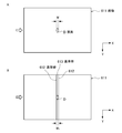
- FIG. 1 is a diagram for explaining an example of a synchronization pattern between the frequency of the driving voltage of the vibration element 31 and the voltage charging timing of the charging unit 41.
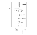
- FIG. 2 is a diagram for explaining an example of a configuration of a microchip 2 that can be mounted on a flow cytometer 1; 4 is a diagram for explaining a configuration of an orifice 21 of the microchip 2.
- FIG. 4 is a flowchart for explaining control steps for optimizing a fluid stream S in the flow cytometer 1. It is a diagram for explaining the image processing in the image acquisition and the reference line setting step S 2. It is a diagram for explaining an image acquired in the image acquisition pixel information acquisition step S 5. It is a diagram for explaining the image processing in the image acquiring pixel information acquisition step S 5. 6 is a flowchart for explaining a modification of the control step for optimizing the fluid stream S in the flow cytometer 1. It is a diagram for explaining the image processing in the image acquiring satellite information acquisition step S 5.
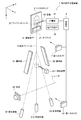
- FIGS. 1 and 2 illustrate a micro particle sorting device 1 according to the present technology configured as a microchip type flow cytometer (hereinafter also referred to as “flow cytometer 1”). It is a schematic diagram explaining the structure of a preparative system.
- the flow cytometer 1 applies a vibration to the orifice 21 formed in the microchip 2 to cause laminar flow between the sample liquid containing cells and the sheath liquid discharged from the orifice 21.
- a vibrating element 31 is provided that is ejected as droplets.
- the vibration element 31 can be a piezo element, for example.
- the discharged droplets are ejected in the positive direction of the arrow Y-axis in the figure as a fluid stream S.
- the microchip 2 is mounted so as to be replaceable.
- the flow cytometer 1 includes a voltage supply unit 32 that supplies a driving voltage to the vibration element 31.
- the vibration element 31 may be configured integrally with the microchip 2, and is disposed on the apparatus side so as to be in contact with the mounted microchip 2. Also good.
- a connector for connecting the vibration element 31 and the voltage supply unit 32 to the flow cytometer 1 is provided.
- the droplet discharged from the orifice 21 is given a positive or negative charge by the charging part 41.
- the charging of the droplet is performed by an electrode 42 that is electrically connected to the charging unit 41 and inserted into the sample inlet 23 provided in the microchip 2.
- the electrode 42 may be inserted into any part of the microchip 2 so as to be in electrical contact with the sample liquid or sheath liquid fed through the flow path.
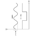
- FIG. 3 shows an example of a synchronization pattern between the frequency of the driving voltage of the vibration element 31 and the voltage charge timing of the charging unit 41.
- Reference sign V in the figure indicates a drive voltage (drive value) of the vibration element 31.
- the flow cytometer 1 includes a pair of deflection plates 51 and 52 arranged to face each other with the fluid stream S interposed therebetween (see FIGS. 1 and 2).
- the deflecting plates 51 and 52 change the traveling direction of each droplet in the fluid stream S by an electric force acting between the electric charges applied to the droplets.
- the deflection plates 51 and 52 may be commonly used electrodes.
- the opposing direction of the polarizing plates 51 and 52 is indicated by the X-axis direction.
- (1-4) Recovery Container The fluid stream that has passed between the deflecting plates 51 and 52 is received by any of the recovery container 811, the recovery container 82, and the recovery container 83.
- the droplet charged negatively by the charging unit 41 is collected in the collection container 82 and the positively charged droplet is collected in the collection container 83.
- the liquid droplets that are not charged by the charging unit 41 fly straight without receiving the electric acting force from the deflecting plates 51 and 52 and are collected in the collection container 811.
- the target cells having the desired characteristics and the other non-target cells are separately collected. Can be recovered.
- the collection container 811 is configured to be retractable from between the deflection plates 51 and 52 (see the block arrow in FIG. 2).
- the collection container 811 accepts droplets that fly straight in the positive direction of the Y axis without being charged.
- the liquid droplets flying straight without being charged are received in the recovery container 812 disposed below the recovery container 811.
- the collection containers 812 are arranged in a line along with the collection containers 82 and 83 in the opposing direction (X-axis direction) of the deflection plates 51 and 52.
- the drawing shows the case where the recovery position of the collection container 811 is set at a predetermined distance from the initial position in the positive Z-axis direction, the retract position of the recovery container 811 is not charged and is positive in the Y-axis positive direction. As long as the droplets that fly straight up to the collection vessel 812 are optional.
- the collection containers 811, 812, 82, 83 may be general-purpose plastic tubes or glass tubes for experiments. These collection containers are preferably disposed on the flow cytometer 1 in a replaceable manner. Moreover, you may connect the drainage path of the collect
- the number of collection containers arranged is not particularly limited. When more than three collection containers are arranged, each droplet is guided to one of the collection containers depending on the presence / absence of the electric acting force between the deflecting plates 51 and 52 and the size thereof. To be.
- the 1st image sensor (camera) which images from the direction (Z-axis direction) to perform is shown.
- the light source 62 illuminates a shooting area of the first camera 61.
- the first camera 61 may be an imaging means such as a CCD camera, a line sensor, or a photoelectric conversion element such as a single plate photodiode.
- a laser light source such as an LED and an LD, a xenon light, an incandescent bulb, or the like can be used.
- Reference numeral 7 in the figure denotes a second imaging element (camera) that images a droplet at a position (break-off point) where the laminar flow of the sample liquid discharged from the orifice 12 and the sheath liquid is turned into a droplet.
- the second camera 7 may be a CCD camera or the like.
- a light source (strobe) (not shown) that illuminates the imaging region may be provided in the same manner as the light source 62 for photographing the droplets by the second camera 7.
- the first camera 61 and the second camera 7 together with the control unit described below function to optimize the fluid stream S so as to be in a straight state without shaking. Control steps for optimizing the fluid stream S will be described later.
- the flow cytometer 1 includes a normal flow cytometer, a light irradiation detection unit for detecting optical characteristics of cells, a data analysis unit for characteristic determination, A tank unit for storing the sample liquid and the sheath liquid and a control unit 9 for controlling each of these components are provided.
- the control unit 9 can be configured by a general-purpose computer including a CPU, a memory, a hard disk, and the like.
- the hard disk stores an OS and a program for executing a control step described below.
- the light irradiation detection unit includes a laser light source, an irradiation system including a condensing lens, a dichroic mirror, a band pass filter, and the like for condensing and irradiating the laser to the cell, and a measurement target generated from the cell by the laser irradiation. And a detection system for detecting light.
- the detection system includes, for example, a PMT (photomultiplier tube), an area imaging device such as a CCD or a CMOS device, or the like.
- the measurement target light detected by the detection system of the light irradiation detection unit is light generated from the cell by irradiation of the measurement light, for example, scattered light such as forward scattered light, side scattered light, Rayleigh scattered light, and Mie scattered light. Or fluorescence. These measurement target lights are converted into electrical signals, output to the control unit 9, and used for determining the optical characteristics of the cells.
- the flow cytometer 1 may be one that detects the characteristics of cells magnetically or electrically.
- a microelectrode is disposed opposite to a sample flow path 22 of the microchip 2 described below, and a resistance value, a capacitance value (capacitance value), an inductance value, an impedance, and a change value of an electric field between the electrodes. Alternatively, magnetization, magnetic field change, magnetic field change, etc. are measured.
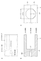
- FIGS. 4 and 5 show an example of the microchip 2 that can be mounted on the flow cytometer 1.
- 4A is a schematic top view
- FIG. 4B is a schematic cross-sectional view corresponding to a PP cross section in A.
- FIG. FIG. 5 is a diagram schematically illustrating the configuration of the orifice 21 of the microchip 2, wherein A is a top view, B is a cross-sectional view, and C is a front view.
- FIG. 5B corresponds to the PP section in FIG. 4A.
- the microchip 2 is formed by bonding the substrate layers 2a and 2b on which the sample channel 22 is formed. Formation of the sample flow path 22 to the substrate layers 2a and 2b can be performed by injection molding of a thermoplastic resin using a mold.
- a thermoplastic resin known plastics can be employed as materials for conventional microchips such as polycarbonate, polymethyl methacrylate resin (PMMA), cyclic polyolefin, polyethylene, polystyrene, polypropylene, and polydimethylsiloxane (PDMS).
- the sample liquid is introduced into the sample inlet 23, merged with the sheath liquid introduced into the sheath inlet 24, and fed through the sample flow path 22.
- the sheath liquid introduced from the sheath inlet 24 is divided and fed in two directions, the sample liquid is sandwiched from the two directions at the junction with the sample liquid introduced from the sample inlet 23. Join.
- a three-dimensional laminar flow in which the sample liquid laminar flow is located at the center of the sheath liquid laminar flow is formed at the junction.
- Reference numeral 25 denotes a suction flow path for eliminating clogging or bubbles by applying a negative pressure in the sample flow path 22 to temporarily reverse the flow when clogging or bubbles are generated in the sample flow path 22.
- a suction outlet 251 connected to a negative pressure source such as a vacuum pump is formed at one end of the suction flow path 25, and the other end is connected to the sample flow path 22 at the communication port 252.
- narrowing portions 261 (see FIG. 4) and 262 (see FIG. 5) formed so that the area of the vertical cross section with respect to the liquid feeding direction is gradually or gradually reduced from the upstream to the downstream of the liquid feeding direction.
- the laminar flow width is narrowed down. Thereafter, the three-dimensional laminar flow is discharged from an orifice 21 provided at one end of the flow path.
- a light irradiation detection unit (not shown) irradiates a laser on cells that are sent in a sample flow path 22 arranged in a line at the center of a three-dimensional laminar flow, and scattering generated from the cells. Light or fluorescence is detected by a photodetector.
- connection part of the sample flow path 22 to the orifice 21 is a straight part 27 formed in a straight line.
- the straight portion 27 functions to eject the fluid stream S straight from the orifice 21 in the positive direction of the Y axis.
- the three-dimensional laminar flow discharged from the orifice 21 is formed into droplets by the vibration applied to the orifice 21 by the vibration element 31 and ejected as a fluid stream S (see FIG. 1).
- the orifice 21 opens in the direction of the end face of the substrate layers 2a and 2b, and a notch 211 is provided between the opening position and the end face of the substrate layer.
- the notch 211 is formed by notching the substrate layers 2 a and 2 b between the opening position of the orifice 21 and the substrate end surface so that the diameter L of the notch 221 is larger than the opening diameter l of the orifice 21. (See FIG. 5C).
- the diameter L of the notch 211 is desirably formed to be twice or more larger than the opening diameter l of the orifice 21 so as not to hinder the movement of the droplets discharged from the orifice 21.
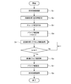
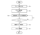
- FIG. 6 is a flowchart illustrating a first procedure of control steps for optimizing the fluid stream S in the flow cytometer 1 in the microparticle sorting apparatus according to the present technology.
- the control steps include “collection container retracting step S 1 ”, “image acquisition / reference band setting step S 2 ”, “charge voltage application step S 3 ”, “drive value adjustment step S 4 ”, “image acquisition / pixel information acquisition”.
- the procedure includes steps S 5 , “optimum drive value search step S 6 ”, “drive value setting step S 7 ”, and “collection container return step S 8 ”.
- each procedure will be described.
- (2-1) Recovery container evacuation step S 1 When the analysis start signal is input by the user, the control unit 9 drives the pump of the tank unit that stores the sample liquid and the sheath liquid, and the sample liquid to the sample inlet 23 and the sheath inlet 24 of the microchip 2 and Start feeding the sheath liquid. Further, the control unit 9 starts applying vibration to the orifice 21 by the vibration element 31. As a result, the three-dimensional laminar flow of the sample liquid and the sheath liquid ejected from the orifice 21 is discharged as droplets, and a fluid stream S is generated. Supply voltage to the vibrating element 31 by the voltage supply unit 32 at this time is assumed to be the initial value V 0.
- the initial value V 0 is a value set according to the opening diameter l (see FIG. 5) of the orifice 21 and the frequency of the vibration element 31.
- the fluid stream S is ejected straight from the orifice 21 and collected in the collection container 811 (see FIG. 1). It is preferable that the liquid droplets collected and stored in the collection container 811 are discharged out of the container from a drainage path connected to the collection container 811.
- the control step for optimizing the fluid stream S is started from step S 1 in which the collection container 811 receiving the fluid stream S ejected from the orifice 21 is retracted from between the deflecting plates 51 and 52.
- the fluid stream S reaches the recovery container 812 disposed below the recovery container 811, and passes through the imaging area by the first camera 61 and the illumination area by the light source 62. Then, it is recovered in the recovery container 812.
- FIG. 2 can be referred to for the retracted position of the collection container 811.
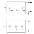
- FIG. 7A shows an example of an acquired image.
- a droplet D at a position where the laser L from the light source 62 is irradiated is detected as a high-luminance pixel (bright spot).
- the droplet D is detected by image recognition of the bright spot, two reference lines 612 and 612 corresponding to the width w of the droplet D are set, and between the reference lines 612 and 612.
- the region is set as the reference band 613 (see FIG. 7B). It is preferable that the image 611 used for image recognition is obtained by integrating images acquired for two or more (preferably a large number) droplets.
- the reference lines 612 and 612 are set in parallel with the ejection direction (Y-axis positive direction) of the fluid stream S. Further, W 1 (width of the reference band 613) the distance between the reference line 612 and 612 is slightly greater than the width w and the same or width w of the droplet D. Later again for a suitable set value of the width W 1 of the reference band 613.
- Position information of the reference line 612 and 612 and the reference zone 613 in the image 611 is stored in the control unit 9, it is used in the subsequent step S 5.
- step S 3 Charge voltage application step S 3
- the charge section 41 which receives the signal from the control unit 9 starts to charge to the droplets.
- the fluid stream S includes droplets having a positive charge, droplets having no charge, and droplets having a negative charge.
- Each droplet receives an electric force acting between the deflecting plates 51 and 52 and travels in a direction corresponding to the electric charge (see FIG. 2).
- step S 4 the control unit 9 outputs a signal to the voltage supply unit 32, by a predetermined width the driving voltage of the vibrating elements 31 from the initial value V 0 increases or decreases.
- the increase width or the decrease width can be appropriately set.
- a case where the voltage is increased by 0.01 V will be described as an example.
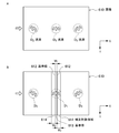
- FIG. 8 shows an example of an acquired image.
- a droplet at a position where the laser L from the light source 62 is irradiated is detected as a bright spot.
- the droplet D 1 to straight drop into the collection container 812 not have charge (see FIG.
- the image 610 is obtained by integrating images acquired for two or more (preferably many) droplets.
- the droplets D 1 , D 2 , and D 3 are not detected as one bright spot as shown in FIG. As shown in FIG. 8B, each is detected as a plurality of divided bright spots. This is because the fluid stream S is in a shaken state, and thus the positions of the droplets D 1 , D 2 , D 3 between the images constituting the integrated image vary. It is. Variation in position of the droplet D 1 is caused to a slight charge to a part of the droplets D 1 constituting the main stream will have been granted.
- variations in the positions of the droplets D 2 and D 3 also occur due to variations in charge between the droplets D 2 constituting the side stream or between the droplets D 3 .
- the traveling direction cannot be precisely controlled, and the droplets D 1 , D 2 , D 3 can be sorted into the collection containers 812, 82, 83, respectively. It may disappear or the sorting accuracy will be reduced.
- step S 5 and subsequent optimal drive value search step S 6 the search for the drive value V such that the optimal condition that does not cause Gabure fluid stream S is performed.
- the control unit 9 includes reference lines 612 and 612 in the image 610 based on the position information of the reference lines 612 and 612 and the reference band 613 set in the image 611 in step S 2 described above. And a reference band 613 is set (see FIG. 9B). Then, the number of pixels (pixel information) of bright spots detected in an area within the predetermined number of pixels from the reference band 613 (the correction target area 614 in the figure) is calculated.
- Reference zone 613 is an area where a bright spot from the droplet D before charging starts in the image 611 acquired in step S 2 described above is detected, the droplets D 1 to form a main stream in the image 610 Among these, a bright spot derived from a droplet that has no charge and falls straight to the recovery container 812 (see FIG. 2) is detected.
- the correction target region 614 in the image 610, of the droplet D 1 to form a main stream a small charge is applied, in the region where the bright spot derived from the droplets is a cause of variation is detected is there.
- the width W 1 of the reference zone 613 is preferably the same as the width of the droplet D w (see FIG. 7), the bright spot derived from the droplets is a cause of variation in the reference zone 613 is detected As long as it is not done, it may be set larger than the width w. Further, the width W 2 of the correction target region 614 may be an appropriate number of pixels from the reference line 612. However, if the width W 2 is too large, the bright spots derived from the droplets D 2 and D 3 constituting the side stream are detected in the correction target region 614, which is not preferable.
- This step S 5 is repeatedly executed a plurality of times, the acquisition of the image 610 different values drive value V of the resonator element 31, the number of pixels of the bright points are detected in the correction target region 614 in the image 610 (pixel information) Is calculated and stored.
- the drive value V of the vibration element 31 is increased by 0.01V
- the drive value is set to (V 0 +0.01) V for the first time, image acquisition and pixel count calculation are performed, and then the Nth time.
- the drive value is (V 0 + 0.01 ⁇ N) V, image acquisition and pixel count calculation are performed.
- the number of repetitions N can be set as appropriate, but can be, for example, about 10 times.
- Optimal drive value search step S 6 After an image acquisition pixel information acquisition step S 5 were repeated predetermined number of times, the control unit 9, the less the number of pixels detected as bright points in the correction target region 614, the optimal drive value V s of preferably minimized To decide. Specifically, 1-between each image 610 obtained by the image obtaining pixel information acquisition step S 5 to N-th, the number of pixels of the bright points are detected in the correction target region 614 (pixel information) Compare. Then, identify the number of iterations the number of pixels becomes minimized, obtaining a drive value V when the as the optimal drive value V s.
- Reducing the number of bright spot pixels detected in the correction target region 614 is substantially the same as increasing the number of bright spot pixels detected in the reference band 613.
- Bright spot detected in the correction target region 614 of the droplet D 1 to form a main stream a small charge is applied is derived from the droplets is a cause of fluctuation.
- the bright spot is detected in the reference zone 613, of the droplet D 1 to form a main stream, those derived from droplets straightly falls into the collection container 812 not have charge (see Fig. 2) It is. Accordingly, by minimizing the number of detected pixels of the bright spots detected in the correction target area 614, it is possible to eliminate the main stream blur.
- the side stream does not cause blurring, and enters the recovery container 82 or the recovery container 83 directly into the inner space of the recovery container 82 or 83 so that the liquid droplets are stored in the recovery containers 82 and 83 in advance. It is desirable to be able to reach the liquid directly. If the side stream is shaken, the liquid droplets that have entered the collection containers 82 and 83 collide with the inner wall surfaces of the containers, damage the cells contained in the liquid droplets, and reduce the survival rate of the collected cells. May end up. In order to prevent droplets from colliding with the inner wall surface, it is effective to set the opening diameter of the collection containers 82 and 83 to about 50% or less of the inner diameter of the container and adjust the position of the side stream so as to enter the opening straight. It is.
- the drive value V of the vibration element 31 is automatically adjusted so as to generate a straight fluid stream S without blurring. For this reason, in the flow cytometer 1, the fluid stream optimizing operation by manual operation, which has been necessary every time the microchip is replaced or measured, is unnecessary, and simple and highly accurate analysis is possible. .
- control step of the optimization control of the fluid stream in the microparticle sorting device the image acquiring pixel information acquisition step S 5, the image processing of the image acquired by the first camera 61
- the first procedure for obtaining the drive value V s of the vibration element 31 that can optimize the fluid stream S has been described.
- the microparticle sorting apparatus according to the present technology is optimized by performing processing using the image acquired by the second camera 7 in addition to processing using the image acquired by the first camera 61.
- the fluid stream S can be maintained in a stable state.
- FIG. 10 is a flowchart illustrating a second procedure of control steps for optimizing the fluid stream S in the flow cytometer 1.
- the control steps are “charge voltage application step S 13 ”, “drive value adjustment step S 14 ”, “image acquisition / satellite information acquisition step S 15 ”, “optimum drive value search step S 16 ” and “drive value setting step S”. 17 ”.
- charge voltage application step S 13 “drive value adjustment step S 14 ”
- image acquisition / satellite information acquisition step S 15 “optimum drive value search step S 16 ”
- drive value setting step S”. 17 drive value setting step S.
- the control unit 9 drives the pump of the tank unit that stores the sample liquid and the sheath liquid, and the sample liquid to the sample inlet 23 and the sheath inlet 24 of the microchip 2 and Start feeding the sheath liquid. Further, the control unit 9 starts applying vibration to the orifice 21 by the vibration element 31. As a result, the three-dimensional laminar flow of the sample liquid and the sheath liquid ejected from the orifice 21 is discharged as droplets, and a fluid stream S is generated. Supply voltage to the vibrating element 31 by the voltage supply unit 32 at this time is set to the optimum value V s, which is set in the first procedure described above. The fluid stream S is ejected straight from the orifice 21 and collected in the collection container 811 (see FIG. 1).
- the charging part 41 which receives the signal from the control unit 9 starts to charge to the droplets.
- the fluid stream S includes droplets having a positive charge, droplets having no charge, and droplets having a negative charge.
- Each droplet receives an electric force acting between the deflecting plates 51 and 52 and travels in a direction corresponding to the electric charge (see FIG. 2).
- step S 14 The drive value adjustment step S 14
- the control unit 9 outputs a signal to the voltage supply unit 32, thereby increasing or decreasing by a predetermined width the driving voltage of the vibrating elements 31 from the optimum value V s.
- Change width of the drive voltage in the step S 14 that is preferably less than (0.01 V in the above example) variation in step S 4 of the first procedure described above.
- symbol F indicates a three-dimensional laminar flow discharged from the orifice 21
- symbols D a and D b indicate droplets.
- a position (break-off point) where the three-dimensional laminar flow F is formed into droplets by vibration applied from the vibration element 31 to the orifice 21 is indicated by a block arrow in the figure.
- 3D laminar flow and the droplet (last droplet) D a containing cell immediately after being separated from the F the 3-dimensional laminar flow F the distance between the Y-axis positive direction end indicated at H.
- the droplet (satellite) d a is located between the last droplet D a and the three-dimensional laminar flow F.
- the last droplet D a and the droplet D b shown in the figure are droplets formed in synchronization with the frequency of vibration applied from the vibration element 31 to the orifice 21, and are liquids used for sorting cells. It is a drop.
- satellites d a , d b and d c shown in the figure are droplets formed asynchronously with the frequency of the vibration element 31 and are droplets that do not contribute to analysis.
- the inventors of the present invention have a length h along the traveling direction (Y-axis direction) of the satellite d a that is 30 to 70% of the distance H between the last droplet D a and the end of the three-dimensional laminar flow F. In some cases, it has been found that the fluid stream optimized in the first procedure described above can be stabilized without blurring.
- this step S 15 the calculation of the detection and the ratio of the distance H and the length h by image recognition of the image 71 (satellite information) is performed.
- This step S 15 is repeatedly executed a plurality of times, the acquisition of the image 71, the calculation of the ratio of the distance H and the length h is performed drive value V of the resonator element 31 as different values.
- the drive value V of the vibration element 31 is increased by 0.001 V
- image acquisition and ratio calculation are performed, and then the Nth time.
- the drive value is (V s + 0.001 ⁇ N) V and image acquisition and ratio calculation are performed.
- the number of repetitions N can be set as appropriate, but can be, for example, about 10 times.
- Optimal drive value search step S 16 After image acquisition, the satellite information acquisition step S 15 is repeated predetermined number of times, the control unit 9, the ratio of the length h for the distance H determines the second optimum drive value V s' to be 30-70%. Specifically, between 1 ⁇ N th until image acquisition Satellite information acquisition step S 15 the images 71 acquired in, comparing the ratio of the length h for the distance H. Then, the number of repetitions at which the ratio becomes 30 to 70% is specified, and the drive value V at that time is obtained as the second optimum drive value V s ′.
- step S 17 the control unit 9 sets the driving voltage supplied from the voltage supply unit 32 to the vibrating element 31, the second optimal drive value V s' determined at the optimal drive value search step S 16 Start cell analysis and sorting. With the second optimum drive value V s ′, it is possible to stably generate a main stream without shaking.
- the fluid stream S is optimized by the image processing of the image acquired by the second camera 7 in combination with the image processing of the image acquired by the first camera 61. be able to.
- the flow cytometer 1 can finely adjust the optimum drive value V s set in the first procedure so that the straight fluid stream S without blur is stably formed.
- the length h of the satellite d a may become very short.
- the drive value V is adjusted in the second procedure and an attempt is made to set the length h to a length in the above-described range
- the fluid stream S optimized in the first procedure will be shaken again. May end up.
- satellites d a suitable length as the image of the second camera 7 acquires the image captured To be presented to the user.
- Can increase the length h of the satellite d a by faster emission timing of the strobe can shorten the length h by slow light emission timing.
- the fine particle sorting apparatus can also have the following configuration.
- a voltage supply unit that supplies a driving voltage to a vibrating element that applies vibration to an orifice that generates a fluid stream, a charging unit that applies a charge to at least a part of droplets discharged from the orifice, and the fluid
- a deflecting plate arranged opposite to the stream and changing the traveling direction of the droplets, and a first image sensor that acquires an image of the droplets passing between the deflecting plates, and Detecting the droplet in the image, setting a reference band corresponding to the width of the droplet before applying the charge, and within the predetermined number of pixels from the reference band of the droplet after applying the charge
- a fine particle sorting device including a control unit that controls the drive voltage of the voltage supply unit so as to reduce the amount of the droplet detected in a region.
- the control unit detects the reference band in the image of the droplet before applying the charge, and sets the fine particle content in the droplet image after applying the charge. Taking device. (3) It has a light source which irradiates a laser to the droplet which passed between the deflection plates, and the control part detects the droplet by image recognition of a bright spot in the image. 2) The fine particle sorting device according to the above. (4) The control unit sets the drive voltage so that the number of pixels of the bright spot detected in an area within a predetermined number of pixels from the reference band in the image of the droplet after applying the charge is smaller. The fine particle sorting apparatus according to (3), which is controlled.
- the first image pickup device picks up an image of the liquid droplets that have passed between the deflection plates from a direction orthogonal to the opposing direction of the fluid stream and the deflection plates.
- a fine particle sorting apparatus according to claim 1.
- the deflecting plate changes the traveling direction of the droplet by an electric force acting between the charge applied to the droplet and the minute particle component according to (1) to (8).
- Taking device. (10) The microparticle sorting apparatus according to any one of (1) to (9), wherein the orifice is formed on a replaceable microchip.
- the fluid stream optimization method may be configured as follows. (11) a first image acquisition procedure for acquiring an image of a droplet in a fluid stream generated from an orifice to which vibration is applied by a vibration element after passing through a deflecting plate that changes the traveling direction of the droplet; , Detecting the droplet in the image, setting a reference band corresponding to the width of the droplet before applying the charge, and within the predetermined number of pixels from the reference band of the droplet after applying the charge And a first voltage control procedure for setting the drive voltage of the vibration element so as to reduce the amount of the droplets detected in a region.
- a fluid stream optimization method in a microparticle sorting apparatus for acquiring an image of a droplet in a fluid stream generated from an orifice to which vibration is applied by a vibration element after passing through a deflecting plate that changes the traveling direction of the droplet; , Detecting the droplet in the image, setting a reference band corresponding to the width of the droplet before applying the charge, and within the predetermined
- the first image acquisition procedure includes a procedure of acquiring an image of the droplet before applying the charge, and a procedure of acquiring an image of the droplet after applying the charge, and the first voltage
- the control procedure includes a procedure for detecting the reference band in the image of the droplet before applying the charge, and a procedure for setting the reference band in the image of the droplet after applying the charge.
- the fluid stream optimization method as described. (13) In the first image acquisition procedure, the droplets that have passed between the deflection plates are irradiated with laser, and in the first voltage control procedure, the droplets are recognized by image recognition of bright spots in the image.
- the fluid stream optimization method according to (11) or (12), wherein the fluid stream is detected.
- the number of pixels of the bright spot detected in a region within a predetermined number of pixels from the reference band in the image of the droplet after applying the charge is reduced.
- (11) including a second voltage control procedure for setting the drive voltage so that the length in the direction along the traveling direction of the droplet positioned between the droplet and the fluid becomes a predetermined length.
- the fluid stream optimizing method 17.
- the second image acquisition unit and the second voltage control procedure are performed after the first image acquisition unit and the first voltage control procedure.
- Stream optimization method (19) The fluid stream according to any one of (16) to (18), wherein the driving voltage is roughly adjusted in the first voltage control procedure, and the driving voltage is finely adjusted in the second voltage control procedure. Optimization method. (20) In the first image acquisition procedure, the droplets that have passed between the deflection plates are imaged from a direction orthogonal to the opposing direction of the fluid stream and the deflection plates.
- the fluid stream optimization method according to any one of the above.
- 1 fine particle sorting device
- 2 microchip
- 23 sample inlet
- 31 vibrating element
- 32 voltage supply unit
- 41 charging unit
- 42 electrode
- 51, 52 deflection plate
- 61 first Camera
- 610, 611, 71 Image
- 612 Reference line
- 613 Reference band
- 614 Area to be corrected
- 62 Light source
- 7 Second camera
- 811, 812, 82, 83 Collection container
- S Fluid stream
Abstract
Description
この微小粒子分取装置は、前記偏向板間を通過した前記液滴にレーザを照射する光源を有していてもよい。この場合、前記制御部は、前記画像中の輝点の画像認識によって前記液滴を検出するものとできる。そして、前記制御部は、前記電荷を付与後の前記液滴の画像において前記基準帯から所定画素数内の領域に検出される前記輝点の画素数がより少なくなるように、前記駆動電圧を制御してもよい。このとき、前記制御部は、前記画素数を最少化するように前記駆動電圧を制御してもよい。
また、この微小粒子分取装置は、前記オリフィスから排出される流体が液滴化される位置において前記液滴の画像を取得する第二の撮像素子を有していてもよい。この場合、前記制御部は、前記画像において、前記流体から分断された直後の微小粒子を含む液滴と、前記流体と、の間に位置する液滴の進行方向に沿う向きの長さが所定長となるように前記駆動電圧を制御するようにできる。
前記所定長は、前記微小粒子を含む液滴と前記流体との間の距離の30~70%であることが好適である。
この微小粒子分取装置において、前記第一の撮像素子は、前記流体ストリーム及び前記偏向板の対向方向に直交する方向から、前記偏向板間を通過した前記液滴を撮像する。また、前記偏向板は、前記液滴に付与された前記電荷との間に作用する電気的な力によって前記液滴の進行方向を変化させる。
この微小粒子分取装置は、前記オリフィスが交換可能なマイクロチップに形成されているマイクロチップ型微小粒子分取装置とできる。
この流体ストリーム最適化方法では、前記第一の画像取得手順において、前記偏向板間を通過した前記液滴にレーザを照射する場合、前記第一の電圧制御手順において、前記画像中の輝点の画像認識によって前記液滴を検出することができる。そして、前記第一の電圧制御手順において、前記電荷を付与後の前記液滴の画像において前記基準帯から所定画素数内の領域に検出される前記輝点の画素数がより少なくなるように、前記駆動電圧を制御してもよい。このとき、前記制御部は、前記画素数を最少化するように前記駆動電圧を制御してもよい。
また、この流体ストリーム最適化方法は、前記オリフィスから排出される流体が液滴化される位置において前記液滴の画像を取得する第二の画像取得手順と、前記画像において、前記流体から分断された直後の微小粒子を含む液滴と、前記流体と、の間に位置する液滴の進行方向に沿う向きの長さが所定長となるように前記駆動電圧を設定する第二の電圧制御手順と、を含んでいてもよい。
この場合、前記所定長は、前記微小粒子を含む液滴と前記流体との間の距離の30~70%であってもよい。
この流体ストリーム最適化方法は、前記第一の画像取得手段及び前記第一の電圧制御手順の後に、前記第二の画像取得手段及び前記第二の電圧制御手順を行い、前記第一の電圧制御手順において前記駆動電圧を粗調整し、前記第二の電圧制御手順において前記駆動電圧を微調整することが好ましい。
この流体ストリーム最適化方法では、前記第一の画像取得手順において、前記流体ストリーム及び前記偏向板の対向方向に直交する方向から、前記偏向板間を通過した前記液滴を撮像する。
生体関連微小粒子には、各種細胞を構成する染色体、リポソーム、ミトコンドリア、オルガネラ(細胞小器官)などが含まれる。細胞には、動物細胞(血球系細胞など)および植物細胞が含まれる。微生物には、大腸菌などの細菌類、タバコモザイクウイルスなどのウイルス類、イースト菌などの菌類などが含まれる。さらに、生体関連微小粒子には、核酸やタンパク質、これらの複合体などの生体関連高分子も包含され得るものとする。また、工業用粒子は、例えば有機もしくは無機高分子材料、金属などであってもよい。有機高分子材料には、ポリスチレン、スチレン・ジビニルベンゼン、ポリメチルメタクリレートなどが含まれる。無機高分子材料には、ガラス、シリカ、磁性体材料などが含まれる。金属には、金コロイド、アルミなどが含まれる。これら微小粒子の形状は、一般には球形であるのが普通であるが、非球形であってもよく、また大きさや質量なども特に限定されない。
1.本技術に係る微小粒子分取装置の構成
(1-1)電圧供給部
(1-2)荷電部
(1-3)偏向板
(1-4)回収容器
(1-5)第一の撮像素子及び第二の撮像素子
(1-6)制御部等
(1-7)マイクロチップ
2.本技術に係る微小粒子分取装置における流体ストリームの最適化制御の第一手順
(2-1)回収容器退避ステップS1
(2-2)画像取得・基準帯設定ステップS2
(2-3)チャージ電圧印加ステップS3
(2-4)ドライブ値調整ステップS4
(2-5)画像取得・ピクセル情報取得ステップS5
(2-6)最適ドライブ値探索ステップS6
(2-7)ドライブ値設定ステップS7
(2-8)回収容器復帰ステップS8
3.本技術に係る微小粒子分取装置における流体ストリームの最適化制御の第二手順
(3-1)チャージ電圧印加ステップS13
(3-2)ドライブ値調整ステップS14
(3-3)画像取得・サテライト情報取得ステップS15
(3-4)最適ドライブ値探索ステップS16
(3-5)ドライブ値設定ステップS17
図1及び図2は、マイクロチップ型フローサイトメータとして構成された本技術に係る微小粒子分取装置1(以下「フローサイトメータ1」とも称する)の分取系の構成を説明する模式図である。
フローサイトメータ1は、マイクロチップ2に形成されたオリフィス21に振動を印加して、オリフィス21から排出される、細胞を含むサンプル液とシース液との層流を液滴化して吐出させる振動素子31を備える。振動素子31は、例えばピエゾ素子とできる。吐出された液滴は、流体ストリームSとなって図中矢印Y軸正方向に射出される。なお、フローサイトメータ1において、マイクロチップ2は交換可能に搭載されるものである。
オリフィス21から吐出される液滴は、荷電部41によって正又は負の電荷を付与される。液滴のチャージは、荷電部41と電気的に接続され、マイクロチップ2に設けられたサンプルインレット23に挿入されている電極42によって行われる。なお、電極42は、マイクロチップ2のいずれかの箇所に、流路を送液されるサンプル液又はシース液に電気的に接触するように挿入されていればよいものとする。
さらに、フローサイトメータ1は、流体ストリームSを挟んで対向して配置された一対の偏向板51,52を備える(図1及び図2参照)。偏向板51,52は、液滴に付与された電荷との間に作用する電気的な力によって流体ストリームS中の各液滴の進行方向を変化させる。偏向板51,52は、通常使用される電極であってよい。図中、偏光板51,52の対向方向をX軸方向によって示す。
偏向板51,52の間を通過した流体ストリームは、回収容器811、回収容器82又は回収容器83のいずれかに受け入れられる。例えば、偏向板51を正、偏向板52を負に帯電させる場合、荷電部41により負にチャージされた液滴は回収容器82に、正にチャージされた液滴は回収容器83にそれぞれ回収される。また、荷電部41によりチャージされていない液滴は、偏向板51,52からの電気的な作用力を受けずに真っ直ぐ飛行し、回収容器811に回収される。フローサイトメータ1では、各液滴に含まれる細胞の特性に応じて該液滴の進行方向を制御することで、所望の特性を有する目的細胞とそれ以外の非目的細胞とを別々の回収容器に回収することができる。
図中符号61は、偏向板51,52の間を通過した液滴を、流体ストリームS及び偏向板51,52の対向方向に直交する方向(Z軸方向)から撮像する第一の撮像素子(カメラ)を示す。光源62は、第一のカメラ61による撮影領域を照明する。第一のカメラ61は、CCDカメラ、ラインセンサ、単板のフォトダイオード等の光電変換素子などの撮像手段であってよい。また、光源62には、LED及びLD等のレーザ光源、キセノンライト又は白熱電球などを用いることができる。
フローサイトメータ1は、上述の構成に加え、通常のフローサイトメータが備える、細胞の光学特性検出のための光照射検出部、特性判定のためのデータ解析部、サンプル液及びシース液を貯留するタンク部及びこれらの各構成を制御するための制御部9などを備える。
図4及び図5に、フローサイトメータ1に搭載可能なマイクロチップ2の一例を示す。図4Aは上面模式図、BはA中P-P断面に対応する断面模式図を示す。また、図5は、マイクロチップ2のオリフィス21の構成を模式的に説明する図であり、Aは上面図、Bは断面図、Cは正面図を示す。図5Bは、図4A中P-P断面に対応する。
図6は、フローサイトメータ1における流体ストリームSの最適化のための制御ステップの第一手順を説明するフローチャートである。制御ステップは、「回収容器退避ステップS1」、「画像取得・基準帯設定ステップS2」、「チャージ電圧印加ステップS3」、「ドライブ値調整ステップS4」、「画像取得・ピクセル情報取得ステップS5」、「最適ドライブ値探索ステップS6」、「ドライブ値設定ステップS7」及び「回収容器復帰ステップS8」の手順を含む。以下、各手順について説明する。
ユーザにより分析の開始信号が入力されると、制御部9は、サンプル液及びシース液を貯留するタンク部のポンプを駆動して、マイクロチップ2のサンプルインレット23及びシースインレット24へのサンプル液及びシース液の送液を開始する。さらに、制御部9は、振動素子31によるオリフィス21への振動印加を開始する。これにより、オリフィス21から射出されるサンプル液及びシース液の3次元層流が液滴化して吐出され、流体ストリームSが発生する。この際の電圧供給部32による振動素子31への供給電圧は初期値V0であるものとする。初期値V0は、オリフィス21の開口径l(図5参照)及び振動素子31の周波数に応じて設定される値である。
本ステップS2では、制御部9からの信号を受けた第一のカメラ61が流体ストリームS中の液滴の画像を取得する。図7Aに、取得される画像の一例を示す。画像611では、光源62からのレーザLが照射される位置(図中ブロック矢印参照)にある液滴Dが、高輝度の画素(輝点)として検出される。
本ステップS3では、制御部9からの信号を受けた荷電部41が、液滴へのチャージを開始する。これにより、流体ストリームS中に正電荷を有する液滴、電荷を有さない液滴、負電荷を有する液滴が含まれるようになる。各液滴は偏向板51,52との間に作用する電気的な力を受けて、その電荷に応じた方向へ進行する(図2参照)。
本ステップS4では、制御部9が電圧供給部32に信号を出力し、振動素子31の駆動電圧を初期値V0から一定幅だけ増加又は減少させる。増加幅あるいは減少幅は、適宜設定され得るものである。ここでは0.01Vずつ増加させる場合を例に説明する。
振動素子31のドライブ値が(V0+0.01)Vに設定されると、制御部9は、第一のカメラ61に信号を出力し、第一のカメラ61が流体ストリームS中の液滴の画像を取得する。図8に、取得される画像の一例を示す。画像610では、光源62からのレーザLが照射される位置(図中ブロック矢印参照)にある液滴が輝点として検出される。画像610では、電荷を有さず回収容器812(図2参照)へ真っ直ぐに落下する液滴D1と、負にチャージされ回収容器82に向かって斜めに落下する液滴D2と、正にチャージされ回収容器83に向かって斜めに落下する液滴D3とが輝点として検出される(図8A参照)。以下、真っ直ぐに落下する液滴D1が形成する流体ストリームを「メインストリーム」、斜めに落下する液滴D2又は液滴D3が形成する流体ストリームを「サイドストリーム」と称するものとする。
画像取得・ピクセル情報取得ステップS5を規定回数繰り返した後、制御部9は、補正対象領域614内に検出される輝点の画素数がより少なくなる、好ましくは最少化する最適ドライブ値Vsを決定する。具体的には、1~N回目までの画像取得・ピクセル情報取得ステップS5において取得された各画像610の間で、補正対象領域614内に検出される輝点の画素数(ピクセル情報)を比較する。そして、画素数が最少となった繰り返し回数を特定し、その際のドライブ値Vを最適ドライブ値Vsとして得る。
本ステップS7では、制御部9は、電圧供給部32から振動素子31に供給される駆動電圧を、最適ドライブ値探索ステップS6で決定された最適ドライブ値Vsに設定する。最適ドライブ値Vsでは、ぶれのないメインストリームを発生させることができる。また、同時に、サイドストリームについても、液滴D2同士又は液滴D3同士の間でのチャージのばらつきをなくして、ぶれが生じないようにできる。
以上のステップが完了し、振動素子31のドライブ値Vが安定したメインストリーム及びサイドストリームを発生する最適値Vsが設定されると、制御部9は、流体ストリームSの最適化のための制御ステップを完了して、細胞の分析・分取を開始する。この際、ステップS1において偏向板51,52との間から退避させた回収容器811は、初期位置に復帰される。回収容器811の初期位置は図1を参照できる。
上述した制御ステップでは、画像取得・ピクセル情報取得ステップS5において、第一のカメラ61により取得された画像の画像処理により流体ストリームSを最適化し得る振動素子31のドライブ値Vsを得る第一手順を説明した。本技術に係る微小粒子分取装置では、第一のカメラ61により取得された画像を用いた処理に併せて、第二のカメラ7により取得された画像を用いた処理を行うことで最適化された流体ストリームSを安定な状態に維持できる。
ユーザにより分析の開始信号が入力されると、制御部9は、サンプル液及びシース液を貯留するタンク部のポンプを駆動して、マイクロチップ2のサンプルインレット23及びシースインレット24へのサンプル液及びシース液の送液を開始する。さらに、制御部9は、振動素子31によるオリフィス21への振動印加を開始する。これにより、オリフィス21から射出されるサンプル液及びシース液の3次元層流が液滴化して吐出され、流体ストリームSが発生する。この際の電圧供給部32による振動素子31への供給電圧は上述の第一手順で設定された最適値Vsとされる。流体ストリームSは、オリフィス21から真っ直ぐ射出され、回収容器811に回収される(図1参照)。
本ステップS14では、制御部9が電圧供給部32に信号を出力し、振動素子31の駆動電圧を最適値Vsから一定幅だけ増加又は減少させる。本ステップS14における駆動電圧の変化幅は、上述した第一手順のステップS4における変化幅(上記例では0.01V)よりも小さくされることが好ましい。
振動素子31のドライブ値が例えば(Vs+0.001)Vに設定されると、制御部9は、第二のカメラ7に信号を出力し、第二のカメラ7が流体ストリームS中の液滴の画像を取得する。図11に、取得される画像の一例を示す。
画像取得・サテライト情報取得ステップS15を規定回数繰り返した後、制御部9は、距離Hに対する長さhの比率が30~70%となる第二の最適ドライブ値Vs´を決定する。具体的には、1~N回目までの画像取得・サテライト情報取得ステップS15において取得された各画像71の間で、距離Hに対する長さhの比率を比較する。そして、比率が30~70%となった繰り返し回数を特定し、その際のドライブ値Vを第二の最適ドライブ値Vs´として得る。
本ステップS17では、制御部9は、電圧供給部32から振動素子31に供給される駆動電圧を、最適ドライブ値探索ステップS16で決定された第二の最適ドライブ値Vs´に設定し、細胞の分析・分取を開始する。第二の最適ドライブ値Vs´では、ぶれのないメインストリームを安定して発生させることができる。
(1)流体ストリームを発生するオリフィスに振動を印加する振動素子に駆動電圧を供給する電圧供給部と、前記オリフィスから吐出される液滴の少なくとも一部に電荷を付与する荷電部と、前記流体ストリームを挟んで対向して配置され、前記液滴の進行方向を変化させる偏向板と、前記偏向板間を通過した前記液滴の画像を取得する第一の撮像素子と、を有し、前記画像中の前記液滴を検出し、前記電荷を付与前の前記液滴の幅に対応する基準帯を設定し、前記電荷を付与後の前記液滴のうち該基準帯から所定画素数内の領域に検出される前記液滴の量をより少なくするように前記電圧供給部の前記駆動電圧を制御する制御部を備える微小粒子分取装置。
(2)前記制御部は、前記電荷を付与前の前記液滴の画像において前記基準帯を検出し、前記電荷付与後の前記液滴の画像中に設定する上記(1)記載の微小粒子分取装置。
(3)前記偏向板間を通過した前記液滴にレーザを照射する光源を有し、前記制御部は、前記画像中の輝点の画像認識によって前記液滴を検出する上記(1)又は(2)記載の微小粒子分取装置。
(4)前記制御部は、前記電荷を付与後の前記液滴の画像において前記基準帯から所定画素数内の領域に検出される前記輝点の画素数がより少なくなるように前記駆動電圧を制御する上記(3)記載の微小粒子分取装置。
(5)前記制御部は、前記画素数を最少化するように前記駆動電圧を制御する上記(4)記載の微小粒子分取装置。
(6)前記オリフィスから排出される流体が液滴化される位置において前記液滴の画像を取得する第二の撮像素子を有し、前記制御部は、前記画像において、前記流体から分断された直後の微小粒子を含む液滴と、前記流体と、の間に位置する液滴の進行方向に沿う向きの長さが所定長となるように前記駆動電圧を制御する上記(1)~(5)のいずれかに記載の微小粒子分取装置。
(7)前記所定長が、前記微小粒子を含む液滴と前記流体との間の距離の30~70%である上記(6)記載の微小粒子分取装置。
(8)前記第一の撮像素子は、前記流体ストリーム及び前記偏向板の対向方向に直交する方向から、前記偏向板間を通過した前記液滴を撮像する上記(1)~(7)のいずれかに記載の微小粒子分取装置。
(9)前記偏向板は、前記液滴に付与された前記電荷との間に作用する電気的な力によって前記液滴の進行方向を変化させる上記(1)~(8)記載の微小粒子分取装置。
(10)前記オリフィスが交換可能なマイクロチップに形成されている上記(1)~(9)のいずれかに記載の微小粒子分取装置。
(11)振動素子により振動を印加されるオリフィスから発生した流体ストリーム中の液滴の画像を、前記液滴の進行方向を変化させる偏向板間を通過した後に取得する第一の画像取得手順と、前記画像中の前記液滴を検出し、電荷を付与前の前記液滴の幅に対応する基準帯を設定し、電荷を付与後の前記液滴のうち該基準帯から所定画素数内の領域に検出される前記液滴の量をより少なくするように前記振動素子の前記駆動電圧を設定する第一の電圧制御手順と、を含む微小粒子分取装置における流体ストリーム最適化方法。
(12)前記第一の画像取得手順は、電荷を付与前の前記液滴の画像を取得する手順と、電荷を付与後の前記液滴の画像を取得する手順を含み、前記第一の電圧制御手順は、前記電荷を付与前の前記液滴の画像において前記基準帯を検出する手順と、前記電荷付与後の前記液滴の画像中に前記基準帯を設定する手順と、を含む上記(11)記載の流体ストリーム最適化方法。
(13)前記第一の画像取得手順において、前記偏向板間を通過した前記液滴にレーザを照射し、前記第一の電圧制御手順において、前記画像中の輝点の画像認識によって前記液滴を検出する上記(11)又は(12)記載の流体ストリーム最適化方法。
(14)前記第一の電圧制御手順において、前記電荷を付与後の前記液滴の画像において前記基準帯から所定画素数内の領域に検出される前記輝点の画素数がより少なくなるように前記駆動電圧を設定する上記(13)記載の流体ストリーム最適化方法。
(15)前記第一の電圧制御手順において、前記画素数を最少化するように前記駆動電圧を制御する上記(14)記載の流体ストリーム最適化方法。
(16)前記オリフィスから排出される流体が液滴化される位置において前記液滴の画像を取得する第二の画像取得手順と、前記画像において、前記流体から分断された直後の微小粒子を含む液滴と、前記流体と、の間に位置する液滴の進行方向に沿う向きの長さが所定長となるように前記駆動電圧を設定する第二の電圧制御手順と、を含む上記(11)~(15)のいずれかに記載の流体ストリーム最適化方法。
(17)前記所定長が、前記微小粒子を含む液滴と前記流体との間の距離の30~70%である上記(16)記載の流体ストリーム最適化方法。
(18)前記第一の画像取得手段及び前記第一の電圧制御手順の後に、前記第二の画像取得手段及び前記第二の電圧制御手順を行う上記(16)又は(17)に記載の流体ストリーム最適化方法。
(19)前記第一の電圧制御手順において前記駆動電圧を粗調整し、前記第二の電圧制御手順において前記駆動電圧を微調整する上記(16)~(18)のいずれかに記載の流体ストリーム最適化方法。
(20)前記第一の画像取得手順において、前記流体ストリーム及び前記偏向板の対向方向に直交する方向から、前記偏向板間を通過した前記液滴を撮像する上記(11)~(19)のいずれかに記載の流体ストリーム最適化方法。
Claims (20)
- 流体ストリームを発生するオリフィスに振動を印加する振動素子に駆動電圧を供給する電圧供給部と、
前記オリフィスから吐出される液滴の少なくとも一部に電荷を付与する荷電部と、
前記流体ストリームを挟んで対向して配置され、前記液滴の進行方向を変化させる偏向板と、
前記偏向板間を通過した前記液滴の画像を取得する第一の撮像素子と、を有し、
前記画像中の前記液滴を検出し、前記電荷を付与前の前記液滴の幅に対応する基準帯を設定し、前記電荷を付与後の前記液滴のうち該基準帯から所定画素数内の領域に検出される前記液滴の量をより少なくするように前記電圧供給部の前記駆動電圧を制御する制御部を備える微小粒子分取装置。 - 前記制御部は、前記電荷を付与前の前記液滴の画像において前記基準帯を検出し、前記電荷付与後の前記液滴の画像中に設定する請求項1記載の微小粒子分取装置。
- 前記偏向板間を通過した前記液滴にレーザを照射する光源を有し、
前記制御部は、前記画像中の輝点の画像認識によって前記液滴を検出する請求項2記載の微小粒子分取装置。 - 前記制御部は、前記電荷を付与後の前記液滴の画像において前記基準帯から所定画素数内の領域に検出される前記輝点の画素数がより少なくなるように前記駆動電圧を制御する請求項3記載の微小粒子分取装置。
- 前記制御部は、前記画素数を最少化するように前記駆動電圧を制御する請求項4記載の微小粒子分取装置。
- 前記オリフィスから排出される流体が液滴化される位置において前記液滴の画像を取得する第二の撮像素子を有し、
前記制御部は、前記画像において、前記流体から分断された直後の微小粒子を含む液滴と、前記流体と、の間に位置する液滴の進行方向に沿う向きの長さが所定長となるように前記駆動電圧を制御する請求項5記載の微小粒子分取装置。 - 前記所定長が、前記微小粒子を含む液滴と前記流体との間の距離の30~70%である請求項6記載の微小粒子分取装置。
- 前記第一の撮像素子は、前記流体ストリーム及び前記偏向板の対向方向に直交する方向から、前記偏向板間を通過した前記液滴を撮像する請求項7記載の微小粒子分取装置。
- 前記偏向板は、前記液滴に付与された前記電荷との間に作用する電気的な力によって前記液滴の進行方向を変化させる請求項8記載の微小粒子分取装置。
- 前記オリフィスが交換可能なマイクロチップに形成されている請求項9記載の微小粒子分取装置。
- 振動素子により振動を印加されるオリフィスから発生した流体ストリーム中の液滴の画像を、前記液滴の進行方向を変化させる偏向板間を通過した後に取得する第一の画像取得手順と、
前記画像中の前記液滴を検出し、電荷を付与前の前記液滴の幅に対応する基準帯を設定し、電荷を付与後の前記液滴のうち該基準帯から所定画素数内の領域に検出される前記液滴の量をより少なくするように前記振動素子の前記駆動電圧を設定する第一の電圧制御手順と、を含む微小粒子分取装置における流体ストリーム最適化方法。 - 前記第一の画像取得手順は、電荷を付与前の前記液滴の画像を取得する手順と、電荷を付与後の前記液滴の画像を取得する手順を含み、
前記第一の電圧制御手順は、前記電荷を付与前の前記液滴の画像において前記基準帯を検出する手順と、前記電荷付与後の前記液滴の画像中に前記基準帯を設定する手順と、を含む請求項11記載の流体ストリーム最適化方法。 - 前記第一の画像取得手順において、前記偏向板間を通過した前記液滴にレーザを照射し、
前記第一の電圧制御手順において、前記画像中の輝点の画像認識によって前記液滴を検出する請求項12記載の流体ストリーム最適化方法。 - 前記第一の電圧制御手順において、前記電荷を付与後の前記液滴の画像において前記基準帯から所定画素数内の領域に検出される前記輝点の画素数がより少なくなるように前記駆動電圧を設定する請求項13記載の流体ストリーム最適化方法。
- 前記第一の電圧制御手順において、前記画素数を最少化するように前記駆動電圧を制御する請求項14記載の流体ストリーム最適化方法。
- 前記オリフィスから排出される流体が液滴化される位置において前記液滴の画像を取得する第二の画像取得手順と、
前記画像において、前記流体から分断された直後の微小粒子を含む液滴と、前記流体と、の間に位置する液滴の進行方向に沿う向きの長さが所定長となるように前記駆動電圧を設定する第二の電圧制御手順と、を含む請求項15記載の流体ストリーム最適化方法。 - 前記所定長が、前記微小粒子を含む液滴と前記流体との間の距離の30~70%である請求項16記載の流体ストリーム最適化方法。
- 前記第一の画像取得手段及び前記第一の電圧制御手順の後に、前記第二の画像取得手段及び前記第二の電圧制御手順を行う請求項17記載の流体ストリーム最適化方法。
- 前記第一の電圧制御手順において前記駆動電圧を粗調整し、前記第二の電圧制御手順において前記駆動電圧を微調整する請求項18記載の流体ストリーム最適化方法。
- 前記第一の画像取得手順において、前記流体ストリーム及び前記偏向板の対向方向に直交する方向から、前記偏向板間を通過した前記液滴を撮像する請求項19記載の流体ストリーム最適化方法。
Priority Applications (5)
| Application Number | Priority Date | Filing Date | Title |
|---|---|---|---|
| CN201380001427.7A CN103718020B (zh) | 2012-03-30 | 2013-02-13 | 微粒分类装置及在该装置中优化流体流的方法 |
| JP2013547044A JP5601424B2 (ja) | 2012-03-30 | 2013-02-13 | 微小粒子分取装置及び該装置における流体ストリーム最適化方法 |
| EP13768656.4A EP2696190B1 (en) | 2012-03-30 | 2013-02-13 | Microparticle fractionation apparatus, and method for optimizing fluid stream in said apparatus |
| US14/118,788 US9087371B2 (en) | 2012-03-30 | 2013-02-13 | Microparticle sorting device and method of optimizing fluid stream therein |
| US14/737,370 US10132735B2 (en) | 2012-03-30 | 2015-06-11 | Microparticle sorting device and method of optimizing fluid stream therein |
Applications Claiming Priority (2)
| Application Number | Priority Date | Filing Date | Title |
|---|---|---|---|
| JP2012080609 | 2012-03-30 | ||
| JP2012-080609 | 2012-03-30 |
Related Child Applications (2)
| Application Number | Title | Priority Date | Filing Date |
|---|---|---|---|
| US14/118,788 A-371-Of-International US9087371B2 (en) | 2012-03-30 | 2013-02-13 | Microparticle sorting device and method of optimizing fluid stream therein |
| US14/737,370 Continuation US10132735B2 (en) | 2012-03-30 | 2015-06-11 | Microparticle sorting device and method of optimizing fluid stream therein |
Publications (1)
| Publication Number | Publication Date |
|---|---|
| WO2013145905A1 true WO2013145905A1 (ja) | 2013-10-03 |
Family
ID=49259188
Family Applications (1)
| Application Number | Title | Priority Date | Filing Date |
|---|---|---|---|
| PCT/JP2013/053324 WO2013145905A1 (ja) | 2012-03-30 | 2013-02-13 | 微小粒子分取装置及び該装置における流体ストリーム最適化方法 |
Country Status (5)
| Country | Link |
|---|---|
| US (2) | US9087371B2 (ja) |
| EP (1) | EP2696190B1 (ja) |
| JP (1) | JP5601424B2 (ja) |
| CN (1) | CN103718020B (ja) |
| WO (1) | WO2013145905A1 (ja) |
Cited By (13)
| Publication number | Priority date | Publication date | Assignee | Title |
|---|---|---|---|---|
| WO2015122071A1 (ja) * | 2014-02-13 | 2015-08-20 | ソニー株式会社 | 粒子分取装置、粒子分取方法、プログラム及び粒子分取システム |
| JP2016057286A (ja) * | 2014-09-05 | 2016-04-21 | ソニー株式会社 | 液滴分取装置、液滴分取方法及びプログラム |
| JP2017122734A (ja) * | 2017-03-02 | 2017-07-13 | ソニー株式会社 | 粒子分取装置、粒子分取方法及びプログラム |
| US10132735B2 (en) | 2012-03-30 | 2018-11-20 | Sony Corporation | Microparticle sorting device and method of optimizing fluid stream therein |
| US10241025B2 (en) | 2013-01-28 | 2019-03-26 | Sony Corporation | Microparticle sorting device, and method and program for sorting microparticles |
| US10309891B2 (en) | 2013-10-16 | 2019-06-04 | Sony Corporation | Particle sorting apparatus, particle sorting method, and program |
| US10451534B2 (en) | 2014-02-14 | 2019-10-22 | Sony Corporation | Particle sorting apparatus and particle sorting method |
| US10605714B2 (en) | 2015-10-19 | 2020-03-31 | Sony Corporation | Image processing device, fine particle sorting device, and image processing method |
| WO2020149042A1 (ja) | 2019-01-15 | 2020-07-23 | ソニー株式会社 | 微小粒子分取装置、微小粒子分取システム、液滴分取装置、及び液滴制御装置、並びに、液滴制御用プログラム |
| CN112730408A (zh) * | 2020-12-24 | 2021-04-30 | 贝克曼库尔特生物科技(苏州)有限公司 | 液流检测系统和液流检测方法以及分选装置 |
| US11193874B2 (en) | 2012-03-30 | 2021-12-07 | Sony Corporation | Micro-particle sorting apparatus and method of determining a trajectory of an ejected stream carrying micro-particles |
| US11492586B2 (en) | 2019-08-05 | 2022-11-08 | Allied Flow Inc. | Particle sorting apparatus and particle sorting method |
| JP7380573B2 (ja) | 2018-03-29 | 2023-11-15 | ソニーグループ株式会社 | 微小粒子分析装置及び微小粒子分析方法 |
Families Citing this family (16)
| Publication number | Priority date | Publication date | Assignee | Title |
|---|---|---|---|---|
| WO2012129591A1 (en) * | 2011-03-30 | 2012-10-04 | Empire Technology Development Llc | Material sorting system and method of sorting material |
| US10723497B2 (en) * | 2014-11-03 | 2020-07-28 | Vanrx Pharmasystems Inc. | Apparatus and method for monitoring and controlling the filling of a container with a pharmaceutical fluid in an aseptic environment |
| JPWO2013145836A1 (ja) | 2012-03-30 | 2015-12-10 | ソニー株式会社 | マイクロチップ型光学測定装置及び該装置における光学位置調整方法 |
| EP2693192B1 (en) | 2012-03-30 | 2019-04-03 | Sony Corporation | Micro-particle isolation device and method for controlling position in the micro-particle isolation device |
| JP5994337B2 (ja) | 2012-03-30 | 2016-09-21 | ソニー株式会社 | 微小粒子分取装置及びディレイタイム決定方法 |
| EP2743673B1 (en) | 2012-07-25 | 2019-11-06 | Sony Corporation | Microparticle measurement device and liquid supply method for microparticle measurement device |
| JP6065527B2 (ja) * | 2012-11-08 | 2017-01-25 | ソニー株式会社 | 微小粒子分取装置及び微小粒子分取方法 |
| CN104969063B (zh) | 2013-02-08 | 2018-05-22 | 索尼公司 | 微粒分析设备和微粒分析系统 |
| JP6136843B2 (ja) | 2013-10-17 | 2017-05-31 | ソニー株式会社 | 粒子分取装置、粒子分取方法及びプログラム |
| CN107303538B (zh) * | 2017-05-23 | 2019-05-31 | 东南大学 | 一种生物分子分离装置及分离方法 |
| JP7088177B2 (ja) * | 2017-05-24 | 2022-06-21 | ソニーグループ株式会社 | 微小粒子の吸引条件の最適化方法及び微小粒子分取装置 |
| CN107297334B (zh) * | 2017-05-31 | 2020-04-17 | 清华大学 | 基于微电火花空化的细胞分选装置和方法 |
| CN108169210A (zh) * | 2018-01-30 | 2018-06-15 | 北京航空航天大学青岛研究院 | 基于表面增强拉曼检测的细胞分选方法及系统 |
| EP3543707B1 (en) | 2018-03-22 | 2023-07-05 | Tecan Trading AG | Optimizing liquid classes for a laboratory automation device |
| CN111879685B (zh) * | 2020-07-31 | 2022-03-18 | 上海微电子装备(集团)股份有限公司 | 一种颗粒分析分选装置及充电延时设置方法 |
| CN112718521A (zh) * | 2020-11-24 | 2021-04-30 | 国家粮食和物资储备局科学研究院 | 一种物料分离系统及方法 |
Citations (7)
| Publication number | Priority date | Publication date | Assignee | Title |
|---|---|---|---|---|
| JP2002505423A (ja) * | 1998-02-27 | 2002-02-19 | サイトメーション, インコーポレイテッド | フローサイトメトリーのための方法および装置 |
| JP2002521658A (ja) * | 1998-07-20 | 2002-07-16 | コールター インターナショナル コーポレイション | フローサイトメータの小滴分離点制御装置及び方法 |
| JP2009145213A (ja) * | 2007-12-14 | 2009-07-02 | Bay Bioscience Kk | 液体フローに含まれる生物学的粒子を分別する装置ならびにその方法 |
| JP2010190680A (ja) | 2009-02-17 | 2010-09-02 | Sony Corp | 微小粒子分取のための装置及びマイクロチップ |
| JP2010216992A (ja) * | 2009-03-17 | 2010-09-30 | Mitsui Eng & Shipbuild Co Ltd | セルソータおよびサンプル分別方法 |
| JP2011232033A (ja) * | 2010-04-23 | 2011-11-17 | Bay Bioscience Corp | フローサイトメータおよびセルソータ |
| JP2011237201A (ja) * | 2010-05-06 | 2011-11-24 | Sony Corp | 微小粒子分取装置、マイクロチップ及びマイクロチップモジュール |
Family Cites Families (118)
| Publication number | Priority date | Publication date | Assignee | Title |
|---|---|---|---|---|
| US3380584A (en) | 1965-06-04 | 1968-04-30 | Atomic Energy Commission Usa | Particle separator |
| BE793185A (fr) | 1971-12-23 | 1973-04-16 | Atomic Energy Commission | Appareil pour analyser et trier rapidement des particules telles que des cellules biologiques |
| US3826364A (en) | 1972-05-22 | 1974-07-30 | Univ Leland Stanford Junior | Particle sorting method and apparatus |
| US3924947A (en) | 1973-10-19 | 1975-12-09 | Coulter Electronics | Apparatus for preservation and identification of particles analyzed by flow-through apparatus |
| US4009435A (en) | 1973-10-19 | 1977-02-22 | Coulter Electronics, Inc. | Apparatus for preservation and identification of particles analyzed by flow-through apparatus |
| DE2632962C3 (de) | 1976-07-22 | 1980-08-21 | Max-Planck-Gesellschaft Zur Foerderung Der Wissenschaften E.V., 3400 Goettingen | Partikelseparator |
| US4173415A (en) | 1976-08-20 | 1979-11-06 | Science Spectrum, Inc. | Apparatus and process for rapidly characterizing and differentiating large organic cells |
| US4223318A (en) * | 1977-12-09 | 1980-09-16 | International Business Machines Corporation | Method and apparatus for compensating for instability of a stream of droplets |
| US4318480A (en) | 1979-08-20 | 1982-03-09 | Ortho Diagnostics, Inc. | Method and apparatus for positioning the point of droplet formation in the jetting fluid of an electrostatic sorting device |
| US4325483A (en) | 1979-08-20 | 1982-04-20 | Ortho Diagnostics, Inc. | Method for detecting and controlling flow rates of the droplet forming stream of an electrostatic particle sorting apparatus |
| US4318481A (en) | 1979-08-20 | 1982-03-09 | Ortho Diagnostics, Inc. | Method for automatically setting the correct phase of the charge pulses in an electrostatic flow sorter |
| JPS5630870A (en) | 1979-08-23 | 1981-03-28 | Fuji Xerox Co Ltd | Ink jet printer |
| US4284496A (en) | 1979-12-10 | 1981-08-18 | Newton William A | Particle guiding apparatus and method |
| US4538733A (en) | 1983-10-14 | 1985-09-03 | Becton, Dickinson And Company | Particle sorter with neutralized collection wells and method of using same |
| JPS6236542A (ja) | 1985-08-09 | 1987-02-17 | Canon Inc | 粒子解析装置 |
| US4616234A (en) | 1985-08-15 | 1986-10-07 | Eastman Kodak Company | Simultaneous phase detection and adjustment of multi-jet printer |
| JPS62167478A (ja) | 1985-11-29 | 1987-07-23 | Shimadzu Corp | 粒子分取装置 |
| JPS6412245A (en) | 1987-07-03 | 1989-01-17 | Canon Kk | Particle analyzing device |
| US4987539A (en) | 1987-08-05 | 1991-01-22 | Stanford University | Apparatus and method for multidimensional characterization of objects in real time |
| US5080770A (en) | 1989-09-11 | 1992-01-14 | Culkin Joseph B | Apparatus and method for separating particles |
| DE69025256T2 (de) | 1989-10-11 | 1996-06-27 | Canon Kk | Gerät und Verfahren zur Trennung von Teilchen aus flüssigkeitssuspendierten Teilchen in Zusammenhang mit deren Eigenschaften |
| JPH06288896A (ja) * | 1993-03-31 | 1994-10-18 | Jasco Corp | セルソータ |
| US5483469A (en) | 1993-08-02 | 1996-01-09 | The Regents Of The University Of California | Multiple sort flow cytometer |
| US5700692A (en) | 1994-09-27 | 1997-12-23 | Becton Dickinson And Company | Flow sorter with video-regulated droplet spacing |
| US5602039A (en) | 1994-10-14 | 1997-02-11 | The University Of Washington | Flow cytometer jet monitor system |
| US6861265B1 (en) | 1994-10-14 | 2005-03-01 | University Of Washington | Flow cytometer droplet formation system |
| US5641457A (en) | 1995-04-25 | 1997-06-24 | Systemix | Sterile flow cytometer and sorter with mechanical isolation between flow chamber and sterile enclosure |
| US5617911A (en) | 1995-09-08 | 1997-04-08 | Aeroquip Corporation | Method and apparatus for creating a free-form three-dimensional article using a layer-by-layer deposition of a support material and a deposition material |
| JP3258889B2 (ja) | 1996-01-11 | 2002-02-18 | 株式会社堀場製作所 | 散乱式粒度分布測定装置における光軸調整方法 |
| US5988480A (en) | 1997-12-12 | 1999-11-23 | Micron Technology, Inc. | Continuous mode solder jet apparatus |
| JP2985826B2 (ja) | 1997-04-09 | 1999-12-06 | 日本電気株式会社 | 位置検出装置および方法 |
| US6202734B1 (en) | 1998-08-03 | 2001-03-20 | Sandia Corporation | Apparatus for jet application of molten metal droplets for manufacture of metal parts |
| US6410872B2 (en) | 1999-03-26 | 2002-06-25 | Key Technology, Inc. | Agricultural article inspection apparatus and method employing spectral manipulation to enhance detection contrast ratio |
| US6372506B1 (en) * | 1999-07-02 | 2002-04-16 | Becton, Dickinson And Company | Apparatus and method for verifying drop delay in a flow cytometer |
| US7024316B1 (en) | 1999-10-21 | 2006-04-04 | Dakocytomation Colorado, Inc. | Transiently dynamic flow cytometer analysis system |
| AU2002211389A1 (en) | 2000-10-03 | 2002-04-15 | California Institute Of Technology | Microfluidic devices and methods of use |
| US7345758B2 (en) | 2001-05-17 | 2008-03-18 | Cytopeia | Apparatus for analyzing and sorting biological particles |
| US6949715B2 (en) | 2002-02-08 | 2005-09-27 | Kelly Arnold J | Method and apparatus for particle size separation |
| US6866370B2 (en) * | 2002-05-28 | 2005-03-15 | Eastman Kodak Company | Apparatus and method for improving gas flow uniformity in a continuous stream ink jet printer |
| US8486618B2 (en) | 2002-08-01 | 2013-07-16 | Xy, Llc | Heterogeneous inseminate system |
| US7201875B2 (en) | 2002-09-27 | 2007-04-10 | Becton Dickinson And Company | Fixed mounted sorting cuvette with user replaceable nozzle |
| US6941005B2 (en) | 2002-11-01 | 2005-09-06 | Coulter International Corp. | Monitoring and control of droplet sorting |
| JP3979304B2 (ja) | 2003-02-24 | 2007-09-19 | 日本光電工業株式会社 | フローセル位置決め方法およびフローセル位置調整可能なフローサイトメータ |
| EP2308416B1 (en) | 2003-03-28 | 2015-01-07 | Inguran, LLC | Apparatus and methods for providing sex-sorted animal sperm |
| JP4148074B2 (ja) * | 2003-09-05 | 2008-09-10 | ソニー株式会社 | 吐出制御装置、液体吐出装置、液体吐出方法、記録媒体及びプログラム |
| US7425253B2 (en) | 2004-01-29 | 2008-09-16 | Massachusetts Institute Of Technology | Microscale sorting cytometer |
| US7232687B2 (en) | 2004-04-07 | 2007-06-19 | Beckman Coulter, Inc. | Multiple sorter monitor and control subsystem for flow cytometer |
| EP1735428A4 (en) | 2004-04-12 | 2010-11-10 | Univ California | OPTOELECTRONIC TWEEZERS FOR MANIPULATING MICROPARTICLES AND CELLS |
| JP4304120B2 (ja) * | 2004-04-30 | 2009-07-29 | ベイバイオサイエンス株式会社 | 生物学的粒子をソーティングする装置及び方法 |
| US7410233B2 (en) * | 2004-12-10 | 2008-08-12 | Konica Minolta Holdings, Inc. | Liquid droplet ejecting apparatus and a method of driving a liquid droplet ejecting head |
| JP4047336B2 (ja) * | 2005-02-08 | 2008-02-13 | 独立行政法人科学技術振興機構 | ゲル電極付セルソーターチップ |
| JP4540506B2 (ja) | 2005-03-04 | 2010-09-08 | 三井造船株式会社 | 試料液流の位置制御方法および装置 |
| US7403125B2 (en) | 2005-05-06 | 2008-07-22 | Accuri Cytometers, Inc. | Flow cytometry system with bubble detection |
| US7760355B2 (en) * | 2005-07-27 | 2010-07-20 | The Curators Of The University Of Missouri | Focused droplet nebulizer for evaporative light scattering detector |
| US7518108B2 (en) | 2005-11-10 | 2009-04-14 | Wisconsin Alumni Research Foundation | Electrospray ionization ion source with tunable charge reduction |
| US7901947B2 (en) | 2006-04-18 | 2011-03-08 | Advanced Liquid Logic, Inc. | Droplet-based particle sorting |
| JP4304195B2 (ja) * | 2006-06-13 | 2009-07-29 | ベイバイオサイエンス株式会社 | 生物学的粒子をソーティングする装置及び方法 |
| JP5168837B2 (ja) | 2006-07-27 | 2013-03-27 | ソニー株式会社 | 画像処理装置、画像処理方法およびプログラム |
| WO2008022147A1 (en) | 2006-08-14 | 2008-02-21 | Mayo Foundation For Medical Education And Research | Rare earth nanoparticles |
| US20080067068A1 (en) | 2006-09-19 | 2008-03-20 | Vanderbilt University | DC-dielectrophoresis microfluidic apparatus, and applications of same |
| JP4304634B2 (ja) | 2006-10-23 | 2009-07-29 | ソニー株式会社 | 標識検出装置及び標識検出方法 |
| DE102006056694B4 (de) | 2006-11-30 | 2010-08-05 | Advalytix Ag | Verfahren zum Durchführen einer enzymatischen Reaktion |
| US8290625B2 (en) | 2007-04-04 | 2012-10-16 | Beckman Coulter, Inc. | Flow cytometer sorter |
| US7828420B2 (en) * | 2007-05-16 | 2010-11-09 | Eastman Kodak Company | Continuous ink jet printer with modified actuator activation waveform |
| US7691636B2 (en) | 2007-05-23 | 2010-04-06 | Beckman Coulter, Inc. | Method and apparatus for compensating for variations in particle trajectories in electrostatic sorter for flowcell cytometer |
| US8848199B2 (en) | 2007-07-10 | 2014-09-30 | Massachusetts Institute Of Technology | Tomographic phase microscopy |
| US7880108B2 (en) | 2007-10-26 | 2011-02-01 | Becton, Dickinson And Company | Deflection plate |
| CN101435764B (zh) * | 2007-11-12 | 2013-11-27 | 北京深迈瑞医疗电子技术研究院有限公司 | 一种粒子分析仪及粒子分析方法 |
| US9797010B2 (en) | 2007-12-21 | 2017-10-24 | President And Fellows Of Harvard College | Systems and methods for nucleic acid sequencing |
| CN101279372B (zh) * | 2007-12-28 | 2010-05-19 | 天津大学 | 一种采用电荷振荡法液滴分裂制备微颗粒的方法和装置 |
| CN101220451A (zh) * | 2008-01-22 | 2008-07-16 | 西北工业大学 | 均匀充电金属液滴偏转距离测控装置及其测控方法 |
| JP2009298012A (ja) | 2008-06-13 | 2009-12-24 | Konica Minolta Holdings Inc | 液滴吐出検査装置、液滴吐出検査方法及び画像形成装置 |
| JP4572973B2 (ja) | 2008-06-16 | 2010-11-04 | ソニー株式会社 | マイクロチップ及びマイクロチップにおける送流方法 |
| US8248609B2 (en) | 2008-11-04 | 2012-08-21 | The Johns Hopkins University | Cylindrical illumination confocal spectroscopy system |
| WO2010101926A2 (en) | 2009-03-02 | 2010-09-10 | The Johns Hopkins University | Microfluidic system for high-throughput, droplet-based single molecule analysis with low reagent consumption |
| WO2010129787A2 (en) | 2009-05-08 | 2010-11-11 | The Johns Hopkins University | Single molecule spectroscopy for analysis of cell-free nucleic acid biomarkers |
| WO2010140460A1 (ja) | 2009-06-03 | 2010-12-09 | 株式会社日立ハイテクノロジーズ | フロー式粒子画像解析方法及び装置 |
| JP5304456B2 (ja) | 2009-06-10 | 2013-10-02 | ソニー株式会社 | 微小粒子測定装置 |
| JP5321260B2 (ja) | 2009-06-11 | 2013-10-23 | ソニー株式会社 | 光学的測定装置、並びにフローサイトメーター及び光学的測定方法 |
| US8628648B2 (en) * | 2009-07-07 | 2014-01-14 | The University Of Akron | Apparatus and method for manipulating micro component |
| JP5446563B2 (ja) * | 2009-08-06 | 2014-03-19 | ソニー株式会社 | 微小粒子分取装置、および該微小粒子分取装置を用いたフローサイトメーター |
| US8570511B2 (en) | 2009-09-09 | 2013-10-29 | Brookhaven Science Associates, Llc | Wide size range fast integrated mobility spectrometer |
| US9151646B2 (en) | 2011-12-21 | 2015-10-06 | Deka Products Limited Partnership | System, method, and apparatus for monitoring, regulating, or controlling fluid flow |
| BR112012022638B1 (pt) | 2010-03-09 | 2020-01-28 | Beckman Coulter Inc | método e sistema para cálculo de retardamento de gota para citometria de fluxo |
| WO2011121750A1 (ja) | 2010-03-31 | 2011-10-06 | 古河電気工業株式会社 | 光情報解析装置及び光情報解析方法 |
| US8922636B1 (en) | 2010-08-20 | 2014-12-30 | The United States Of America As Represented By The Secretary Of The Navy | Synthetic aperture imaging for fluid flows |
| JP2012047464A (ja) | 2010-08-24 | 2012-03-08 | Sony Corp | 微小粒子測定装置及び光軸補正方法 |
| US9170138B2 (en) | 2010-10-01 | 2015-10-27 | The Board Of Trustees Of The Leland Stanford Junior University | Enhanced microfluidic electromagnetic measurements |
| US8705031B2 (en) | 2011-02-04 | 2014-04-22 | Cytonome/St, Llc | Particle sorting apparatus and method |
| WO2012129591A1 (en) | 2011-03-30 | 2012-10-04 | Empire Technology Development Llc | Material sorting system and method of sorting material |
| US20120301869A1 (en) | 2011-05-25 | 2012-11-29 | Inguran, Llc | Particle separation devices, methods and systems |
| JP5847924B2 (ja) | 2011-06-08 | 2016-01-27 | エンパイア テクノロジー ディベロップメント エルエルシー | 拡張現実表現のための二次元画像取込み |
| JP6003020B2 (ja) | 2011-08-03 | 2016-10-05 | ソニー株式会社 | マイクロチップ及び微小粒子分析装置 |
| WO2013028947A1 (en) | 2011-08-25 | 2013-02-28 | Sony Corporation | Characterization of motion-related error in a stream of moving micro-entities |
| JP5880088B2 (ja) | 2012-01-31 | 2016-03-08 | ブラザー工業株式会社 | エッジ検出装置、画像データ処理装置、該画像データ処理装置を備える液体吐出装置、エッジ検出方法及びエッジ検出プログラム |
| US9324190B2 (en) | 2012-02-24 | 2016-04-26 | Matterport, Inc. | Capturing and aligning three-dimensional scenes |
| JP5924077B2 (ja) | 2012-03-30 | 2016-05-25 | ソニー株式会社 | 微小粒子分取装置及び微小粒子分取装置における軌道方向判定方法 |
| JP5601424B2 (ja) | 2012-03-30 | 2014-10-08 | ソニー株式会社 | 微小粒子分取装置及び該装置における流体ストリーム最適化方法 |
| JP5994337B2 (ja) | 2012-03-30 | 2016-09-21 | ソニー株式会社 | 微小粒子分取装置及びディレイタイム決定方法 |
| JPWO2013145836A1 (ja) | 2012-03-30 | 2015-12-10 | ソニー株式会社 | マイクロチップ型光学測定装置及び該装置における光学位置調整方法 |
| EP2693192B1 (en) | 2012-03-30 | 2019-04-03 | Sony Corporation | Micro-particle isolation device and method for controlling position in the micro-particle isolation device |
| JP5924276B2 (ja) | 2012-04-03 | 2016-05-25 | ソニー株式会社 | 流路デバイス、粒子分取装置及び粒子分取方法 |
| US9448157B2 (en) | 2012-07-18 | 2016-09-20 | Sony Corporation | Microparticle sorting apparatus, microchip for sorting microparticles and microparticle sorting method |
| JP2014020918A (ja) | 2012-07-18 | 2014-02-03 | Sony Corp | 微小粒子測定装置及び微小粒子分析方法 |
| EP2743673B1 (en) | 2012-07-25 | 2019-11-06 | Sony Corporation | Microparticle measurement device and liquid supply method for microparticle measurement device |
| US9168568B2 (en) | 2012-08-01 | 2015-10-27 | Owl biomedical, Inc. | Particle manipulation system with cytometric confirmation |
| JP2014062822A (ja) | 2012-09-21 | 2014-04-10 | Sony Corp | 微小粒子分析装置及び微小粒子分析方法 |
| JP6065527B2 (ja) | 2012-11-08 | 2017-01-25 | ソニー株式会社 | 微小粒子分取装置及び微小粒子分取方法 |
| EP3910318A1 (en) | 2013-01-28 | 2021-11-17 | Sony Group Corporation | Microparticle sorting device, and method and program for sorting microparticles |
| CN104969063B (zh) | 2013-02-08 | 2018-05-22 | 索尼公司 | 微粒分析设备和微粒分析系统 |
| JP2014174139A (ja) | 2013-03-13 | 2014-09-22 | Sony Corp | 流路デバイス、粒子分取装置、粒子流出方法、及び粒子分取方法 |
| WO2014194042A2 (en) | 2013-05-29 | 2014-12-04 | Gnubio, Inc. | Low cost optical high speed discrete measurement system |
| WO2015056516A1 (ja) | 2013-10-16 | 2015-04-23 | ソニー株式会社 | 粒子分取装置、粒子分取方法及びプログラム |
| JP6136843B2 (ja) | 2013-10-17 | 2017-05-31 | ソニー株式会社 | 粒子分取装置、粒子分取方法及びプログラム |
| CN105980831B (zh) | 2014-02-13 | 2021-01-12 | 索尼公司 | 粒子分捡装置、粒子分捡方法、程序以及粒子分捡系统 |
| JP6102783B2 (ja) | 2014-02-14 | 2017-03-29 | ソニー株式会社 | 粒子分取装置、粒子分取方法及びプログラム |
| JP6657625B2 (ja) | 2014-09-05 | 2020-03-04 | ソニー株式会社 | 液滴分取装置、液滴分取方法及びプログラム |
| CN106663411A (zh) | 2014-11-16 | 2017-05-10 | 易欧耐特感知公司 | 用于增强现实准备、处理和应用的系统和方法 |
-
2013
- 2013-02-13 JP JP2013547044A patent/JP5601424B2/ja active Active
- 2013-02-13 CN CN201380001427.7A patent/CN103718020B/zh active Active
- 2013-02-13 US US14/118,788 patent/US9087371B2/en active Active
- 2013-02-13 WO PCT/JP2013/053324 patent/WO2013145905A1/ja active Application Filing
- 2013-02-13 EP EP13768656.4A patent/EP2696190B1/en active Active
-
2015
- 2015-06-11 US US14/737,370 patent/US10132735B2/en active Active
Patent Citations (7)
| Publication number | Priority date | Publication date | Assignee | Title |
|---|---|---|---|---|
| JP2002505423A (ja) * | 1998-02-27 | 2002-02-19 | サイトメーション, インコーポレイテッド | フローサイトメトリーのための方法および装置 |
| JP2002521658A (ja) * | 1998-07-20 | 2002-07-16 | コールター インターナショナル コーポレイション | フローサイトメータの小滴分離点制御装置及び方法 |
| JP2009145213A (ja) * | 2007-12-14 | 2009-07-02 | Bay Bioscience Kk | 液体フローに含まれる生物学的粒子を分別する装置ならびにその方法 |
| JP2010190680A (ja) | 2009-02-17 | 2010-09-02 | Sony Corp | 微小粒子分取のための装置及びマイクロチップ |
| JP2010216992A (ja) * | 2009-03-17 | 2010-09-30 | Mitsui Eng & Shipbuild Co Ltd | セルソータおよびサンプル分別方法 |
| JP2011232033A (ja) * | 2010-04-23 | 2011-11-17 | Bay Bioscience Corp | フローサイトメータおよびセルソータ |
| JP2011237201A (ja) * | 2010-05-06 | 2011-11-24 | Sony Corp | 微小粒子分取装置、マイクロチップ及びマイクロチップモジュール |
Non-Patent Citations (1)
| Title |
|---|
| See also references of EP2696190A4 |
Cited By (22)
| Publication number | Priority date | Publication date | Assignee | Title |
|---|---|---|---|---|
| US11193874B2 (en) | 2012-03-30 | 2021-12-07 | Sony Corporation | Micro-particle sorting apparatus and method of determining a trajectory of an ejected stream carrying micro-particles |
| US10132735B2 (en) | 2012-03-30 | 2018-11-20 | Sony Corporation | Microparticle sorting device and method of optimizing fluid stream therein |
| US10241025B2 (en) | 2013-01-28 | 2019-03-26 | Sony Corporation | Microparticle sorting device, and method and program for sorting microparticles |
| US11313784B2 (en) | 2013-01-28 | 2022-04-26 | Sony Corporation | Microparticle sorting device, and method and program for sorting microparticles |
| US10309891B2 (en) | 2013-10-16 | 2019-06-04 | Sony Corporation | Particle sorting apparatus, particle sorting method, and program |
| US11119030B2 (en) | 2014-02-13 | 2021-09-14 | Sony Corporation | Particle sorting device, particle sorting method, program, and particle sorting system |
| WO2015122071A1 (ja) * | 2014-02-13 | 2015-08-20 | ソニー株式会社 | 粒子分取装置、粒子分取方法、プログラム及び粒子分取システム |
| US10309892B2 (en) | 2014-02-13 | 2019-06-04 | Sony Corporation | Particle sorting device, particle sorting method, program, and particle sorting system |
| JPWO2015122071A1 (ja) * | 2014-02-13 | 2017-03-30 | ソニー株式会社 | 粒子分取装置、粒子分取方法、プログラム及び粒子分取システム |
| US10451534B2 (en) | 2014-02-14 | 2019-10-22 | Sony Corporation | Particle sorting apparatus and particle sorting method |
| US10386287B2 (en) | 2014-09-05 | 2019-08-20 | Sony Corporation | Droplet sorting device, droplet sorting method and program |
| JP2016057286A (ja) * | 2014-09-05 | 2016-04-21 | ソニー株式会社 | 液滴分取装置、液滴分取方法及びプログラム |
| JP2020076786A (ja) * | 2014-09-05 | 2020-05-21 | ソニー株式会社 | 液滴分取装置、液滴分取方法及びプログラム |
| US10876952B2 (en) | 2014-09-05 | 2020-12-29 | Sony Corporation | Droplet sorting device, droplet sorting method and program |
| US10605714B2 (en) | 2015-10-19 | 2020-03-31 | Sony Corporation | Image processing device, fine particle sorting device, and image processing method |
| US11204309B2 (en) | 2015-10-19 | 2021-12-21 | Sony Corporation | Image processing device, fine particle sorting device, and image processing method |
| JP2017122734A (ja) * | 2017-03-02 | 2017-07-13 | ソニー株式会社 | 粒子分取装置、粒子分取方法及びプログラム |
| JP7380573B2 (ja) | 2018-03-29 | 2023-11-15 | ソニーグループ株式会社 | 微小粒子分析装置及び微小粒子分析方法 |
| WO2020149042A1 (ja) | 2019-01-15 | 2020-07-23 | ソニー株式会社 | 微小粒子分取装置、微小粒子分取システム、液滴分取装置、及び液滴制御装置、並びに、液滴制御用プログラム |
| US11885730B2 (en) | 2019-01-15 | 2024-01-30 | Sony Group Corporation | Microparticle sorting device, microparticle sorting system, droplet sorting device, droplet control device, and droplet control program |
| US11492586B2 (en) | 2019-08-05 | 2022-11-08 | Allied Flow Inc. | Particle sorting apparatus and particle sorting method |
| CN112730408A (zh) * | 2020-12-24 | 2021-04-30 | 贝克曼库尔特生物科技(苏州)有限公司 | 液流检测系统和液流检测方法以及分选装置 |
Also Published As
| Publication number | Publication date |
|---|---|
| US20150285727A1 (en) | 2015-10-08 |
| EP2696190A4 (en) | 2014-09-24 |
| JP5601424B2 (ja) | 2014-10-08 |
| EP2696190A1 (en) | 2014-02-12 |
| US20140193059A1 (en) | 2014-07-10 |
| JPWO2013145905A1 (ja) | 2015-12-10 |
| CN103718020A (zh) | 2014-04-09 |
| US10132735B2 (en) | 2018-11-20 |
| EP2696190B1 (en) | 2016-04-13 |
| CN103718020B (zh) | 2016-06-29 |
| US9087371B2 (en) | 2015-07-21 |
Similar Documents
| Publication | Publication Date | Title |
|---|---|---|
| JP5601424B2 (ja) | 微小粒子分取装置及び該装置における流体ストリーム最適化方法 | |
| JP6958650B2 (ja) | 液滴分取装置、液滴分取方法及びプログラム | |
| JP6102994B2 (ja) | 微小粒子分取装置及び微小粒子分取装置における位置制御方法 | |
| JP6729597B2 (ja) | 画像処理装置、微小粒子分取装置及び画像処理方法 | |
| JP5994337B2 (ja) | 微小粒子分取装置及びディレイタイム決定方法 | |
| JP5924077B2 (ja) | 微小粒子分取装置及び微小粒子分取装置における軌道方向判定方法 | |
| JP6256537B2 (ja) | マイクロチップ型光学測定装置及び該装置における光学位置調整方法 | |
| JP2024010163A (ja) | 微小粒子分析装置及び微小粒子分析方法 | |
| JP5905317B2 (ja) | 微小粒子分取装置におけるキャリブレーション方法及び該装置 | |
| JP6237806B2 (ja) | 微小粒子分取装置 | |
| JP5978715B2 (ja) | 微小粒子分取装置及び微小粒子分取装置の制御方法 | |
| JP6135796B2 (ja) | 微小粒子分取装置及び微小粒子分取装置における軌道方向判定方法 |
Legal Events
| Date | Code | Title | Description |
|---|---|---|---|
| ENP | Entry into the national phase |
Ref document number: 2013547044 Country of ref document: JP Kind code of ref document: A |
|
| WWE | Wipo information: entry into national phase |
Ref document number: 2013768656 Country of ref document: EP |
|
| WWE | Wipo information: entry into national phase |
Ref document number: 14118788 Country of ref document: US |
|
| 121 | Ep: the epo has been informed by wipo that ep was designated in this application |
Ref document number: 13768656 Country of ref document: EP Kind code of ref document: A1 |
|
| NENP | Non-entry into the national phase |
Ref country code: DE |
|
| NENP | Non-entry into the national phase |
Ref country code: DE |