WO2013145449A1 - 媒体収納繰出装置及び媒体処理装置 - Google Patents
媒体収納繰出装置及び媒体処理装置 Download PDFInfo
- Publication number
- WO2013145449A1 WO2013145449A1 PCT/JP2012/081295 JP2012081295W WO2013145449A1 WO 2013145449 A1 WO2013145449 A1 WO 2013145449A1 JP 2012081295 W JP2012081295 W JP 2012081295W WO 2013145449 A1 WO2013145449 A1 WO 2013145449A1
- Authority
- WO
- WIPO (PCT)
- Prior art keywords
- tape
- reel
- drum
- rotation
- rotation shaft
- Prior art date
- Legal status (The legal status is an assumption and is not a legal conclusion. Google has not performed a legal analysis and makes no representation as to the accuracy of the status listed.)
- Ceased
Links
Images






Classifications
-
- B—PERFORMING OPERATIONS; TRANSPORTING
- B65—CONVEYING; PACKING; STORING; HANDLING THIN OR FILAMENTARY MATERIAL
- B65H—HANDLING THIN OR FILAMENTARY MATERIAL, e.g. SHEETS, WEBS, CABLES
- B65H5/00—Feeding articles separated from piles; Feeding articles to machines
- B65H5/28—Feeding articles stored in rolled or folded bands
-
- B—PERFORMING OPERATIONS; TRANSPORTING
- B65—CONVEYING; PACKING; STORING; HANDLING THIN OR FILAMENTARY MATERIAL
- B65H—HANDLING THIN OR FILAMENTARY MATERIAL, e.g. SHEETS, WEBS, CABLES
- B65H29/00—Delivering or advancing articles from machines; Advancing articles to or into piles
- B65H29/006—Winding articles into rolls
-
- G—PHYSICS
- G07—CHECKING-DEVICES
- G07D—HANDLING OF COINS OR VALUABLE PAPERS, e.g. TESTING, SORTING BY DENOMINATIONS, COUNTING, DISPENSING, CHANGING OR DEPOSITING
- G07D11/00—Devices accepting coins; Devices accepting, dispensing, sorting or counting valuable papers
- G07D11/10—Mechanical details
- G07D11/12—Containers for valuable papers
-
- B—PERFORMING OPERATIONS; TRANSPORTING
- B65—CONVEYING; PACKING; STORING; HANDLING THIN OR FILAMENTARY MATERIAL
- B65H—HANDLING THIN OR FILAMENTARY MATERIAL, e.g. SHEETS, WEBS, CABLES
- B65H2220/00—Function indicators
- B65H2220/09—Function indicators indicating that several of an entity are present
-
- B—PERFORMING OPERATIONS; TRANSPORTING
- B65—CONVEYING; PACKING; STORING; HANDLING THIN OR FILAMENTARY MATERIAL
- B65H—HANDLING THIN OR FILAMENTARY MATERIAL, e.g. SHEETS, WEBS, CABLES
- B65H2301/00—Handling processes for sheets or webs
- B65H2301/40—Type of handling process
- B65H2301/41—Winding, unwinding
- B65H2301/419—Winding, unwinding from or to storage, i.e. the storage integrating winding or unwinding means
- B65H2301/4191—Winding, unwinding from or to storage, i.e. the storage integrating winding or unwinding means for handling articles of limited length, e.g. AO format, arranged at intervals from each other
- B65H2301/41912—Winding, unwinding from or to storage, i.e. the storage integrating winding or unwinding means for handling articles of limited length, e.g. AO format, arranged at intervals from each other between two belt like members
-
- B—PERFORMING OPERATIONS; TRANSPORTING
- B65—CONVEYING; PACKING; STORING; HANDLING THIN OR FILAMENTARY MATERIAL
- B65H—HANDLING THIN OR FILAMENTARY MATERIAL, e.g. SHEETS, WEBS, CABLES
- B65H2403/00—Power transmission; Driving means
- B65H2403/70—Clutches; Couplings
- B65H2403/73—Couplings
- B65H2403/732—Torque limiters
-
- B—PERFORMING OPERATIONS; TRANSPORTING
- B65—CONVEYING; PACKING; STORING; HANDLING THIN OR FILAMENTARY MATERIAL
- B65H—HANDLING THIN OR FILAMENTARY MATERIAL, e.g. SHEETS, WEBS, CABLES
- B65H2701/00—Handled material; Storage means
- B65H2701/10—Handled articles or webs
- B65H2701/19—Specific article or web
- B65H2701/1912—Banknotes, bills and cheques or the like
Definitions
- the present invention relates to a medium storing and feeding apparatus and a medium processing apparatus, and is suitable for application to a temporary holding unit of an automatic teller machine installed in a financial institution, for example.
- An automatic teller machine (hereinafter referred to as an ATM) includes a deposit / withdrawal port portion serving as a bill insertion port and a receipt port, a discrimination unit that discriminates the denomination and authenticity of the bill, and a bill temporarily It is comprised by the temporary storage part to accommodate, the several banknote storage which stores a banknote for every money type, the conveyance path etc. which connect these.
- the temporary storage unit stores and feeds out banknotes by, for example, winding and rewinding the tape between the reel and the drum.
- a temporary storage unit is referred to herein as a drum winding type.
- banknotes are stored and fed out by winding and rewinding the tapes with the banknotes sandwiched between a pair of upper and lower tapes. Things are known.
- FIG. 14 is a side view in which the right side of the drawing is the front side and the left side of the drawing is the rear side.
- the temporary storage unit 200 mainly includes a drum 201, a pair of upper and lower tape reels 202 and 203, a pair of upper and lower tapes 204 and 205, and a plurality of rollers 206 to 210. Is done.
- the upper tape 204 is drawn forward from the upper tape reel 202 disposed on the upper rear side of the cylindrical drum 201, and this is hung on the upper tape roller 206 disposed on the upper front side of the drum 201. After passing, the upper tape roller 206 folds backward and advances to the upper end of the drum 201.
- the lower tape 205 is pulled forward from the lower tape reel 203 disposed on the lower rear side of the drum 201, and this is applied to the lower first tape roller 207 disposed on the lower front side of the drum 201. Hang over. Thereafter, the lower tape roller 207 is moved upward by the lower first tape roller 207, and is further passed over the lower second tape roller 208 disposed at a predetermined interval below the upper tape roller 206. The Thereafter, the lower tape roller 207 is folded back by the lower second tape roller 208 and advanced to the upper end of the drum 201.
- the upper tape 204 and the lower tape 205 are pressed against the upper end of the drum 201 by a pressing roller 209 that is arranged directly above the upper end of the drum 201 so that the upper tape 204 overlaps the lower tape 205.
- Each tip is fixed to the peripheral side surface of the drum 201.
- the temporary storage unit 200 rotates the drum 201 in the winding direction that is counterclockwise in the drawing, so that the upper tape 204 and the lower tape 205 are transferred from the upper tape reel 202 and the lower tape reel 203 to the drum 201. While winding up, the upper tape 204 and the lower tape 205 are rewound from the drum 201 to the upper tape reel 202 and the lower tape reel 203 by rotating in the rewind direction clockwise in the figure. It has become.
- the temporary storage unit 200 has such a configuration, and when the banknotes are stored, the banknotes BL conveyed through the plurality of conveyance rollers 210 arranged in the front are the upper tape roller 206 and the lower second tape roller 208. It is sent between. At this time, the drum 201 is rotated in the direction of winding the tape (referred to as the winding direction), and the upper tape reel 202 and the lower tape reel 203 are rotated in the direction of rewinding the tape (referred to as the rewind direction).
- the banknote BL is accommodated by rotating and pinching the central part of the banknote BL between the upper tape 204 and the lower tape 205 and winding it around the drum 201 together with the upper tape 204 and the lower tape 205.
- the temporary storage unit 200 rotates the drum 201 in the rewinding direction and rotates the upper tape reel 202 and the lower tape reel 203 in the winding direction so as to rotate the upper tape 204 and the lower tape reel.
- the banknote BL is fed out from between the upper tape roller 206 and the lower second tape roller 208 by rewinding the banknote BL from the drum 201 together with the side tape 205.
- the temporary storage unit 200 is configured to store and pay out the bills BL.
- a torque limiter is provided between the tape reel and the reel shaft as a temporary holding unit for winding and rewinding the tape with a bill sandwiched between a pair of upper and lower tapes. Therefore, a tape in which a certain tension is applied to a pair of upper and lower tapes has been proposed (see, for example, Japanese Patent Application Laid-Open No. 2009-107824).
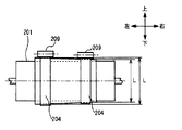
- the winding diameter L of the drum 201 is different at both ends of the drum 201.
- the amount of winding and the amount of unwinding will be different for each set. This results in a difference in tape speed between the pair of upper and lower tape pairs.
- the prior art applies a pair of upper and lower tape tensions. It is a technology that keeps it constant. For this reason, even if a pair of upper and lower tapes is used in a temporary holding section that uses a plurality of sets, the tension of any one of the plurality of sets can only be kept constant. As a result, a plurality of sets of tapes The tension cannot be kept constant.
- the present invention takes the above points into consideration and intends to propose a medium storage and feeding apparatus and a medium processing apparatus that can prevent the occurrence of a failure more reliably than in the past.
- the medium storing and feeding is performed by storing or feeding the medium by winding or rewinding the tape that sandwiches the medium in a pair between the tape reel and the drum.
- a torque control unit is provided to control the torque between each tape reel and reel shaft so that the tension of each tape is constant between the reel and drum. It was so.
- a discrimination unit for discriminating the medium a temporary holding unit for temporarily storing the medium discriminated by the discrimination unit, and a banknote storage for storing the medium fed out from the temporary holding unit
- the temporary holding unit is a drum winding type that stores or feeds the medium by winding or rewinding the tape that sandwiches the medium in a set of two pieces between the tape reel and the drum.
- a plurality of sets of tapes, a plurality of sets of tape reels around which each of the plurality of sets of tapes is wound, and a rotation axis of the tape reel are provided separately for one tape reel and the other tape reel of each set.
- Two reel rotation shafts a drum for winding a medium sandwiched between a plurality of sets of tapes together with a plurality of sets of tapes, and each tape reel are provided independently.
- As the tension of the tape is constant between the beam and to provide a torque control unit for controlling the torque between the tape reel and the reel shaft shaft.
- the tape tension between the respective tape reels and drums can be kept constant, so that it is possible to improve the clamping stability of the medium, and thus more reliably than in the past.
- a medium storage and feeding apparatus and a medium processing apparatus that can prevent the occurrence of a failure can be realized.
- FIG. 1 the outline of the whole structure of the automatic teller machine (ATM) 1 is shown.
- This ATM 1 uses cash cards, banknotes, bankbooks, etc. as a transaction medium, and performs processing such as cash deposits, payments, and transfers by user operations.
- the ATM 1 is provided with a card processor (not shown) for processing a user's cash card and a bankbook processor (not shown) for recording transaction contents in a passbook.
- a card processor (not shown) for processing a user's cash card
- a bankbook processor (not shown) for recording transaction contents in a passbook.
- the card processor processes the user's cash card taken from the card slot 2 provided on the front surface of ATM 1 (the surface facing the user), and the passbook processor is provided on the front surface of ATM 1.
- the passbook taken in from the passbook take-in port 3 is processed.
- the banknote inlet 6 exposed on the front surface of the ATM 1 is provided above the front side of the banknote depositing and dispensing machine 4, and banknotes are deposited and withdrawn through the banknote inlet 6. Further, a coin intake 7 exposed on the front surface of the ATM 1 is provided above the front of the coin depositing and dispensing machine 5, and coins are deposited and withdrawn through the coin intake 7.
- a display operation unit 8 is provided in the center of the front surface of the ATM 1.
- the display operation unit 8 includes, for example, a liquid crystal panel as a display unit and a touch panel as an operation unit, and can display various screens, input a personal identification number and transaction amount, and the like.
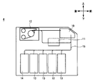
- FIG. 2 is a side view in which the right side of the drawing is the front side and the left side of the drawing is the rear side.
- the banknote depositing / dispensing machine 4 is a so-called recycling-type banknote depositing / dispensing machine that uses the deposited banknotes for withdrawal, and a customer service unit 10, a discrimination unit 11, and a temporary storage unit 12 are arranged on the top thereof. In the lower part, a plurality of banknote storages 13 and reject storages 14 are arranged.
- the customer service unit 10 is arranged above the front surface of the upper part of the banknote depositing / dispensing machine 4, and the customer service unit 10 is provided with the above-described banknote intake 6.
- a discrimination unit 11 for discriminating the authenticity, correctness, denomination, deed, etc. of the bill is arranged at a position lower rearward of the customer service unit 10.
- a temporary storage unit 12 for temporarily storing banknotes is disposed at a position on the upper rear side of the discrimination unit 11.
- the temporary storage unit 12 is a drum winding type temporary storage unit.
- a plurality of vertically long banknote storages 13 are arranged in the front-rear direction at the lower part of the banknote depositing / dispensing machine 4, and a reject box 14 is further arranged behind the last banknote storage 13.
- the banknote depositing / dispensing machine 4 is provided with a conveyance path 15 that connects the customer service section 10, the discrimination section 11, the temporary storage section 12, the plurality of banknote storage boxes 13 and the rejection box 14, and this conveyance path 15 is connected to the banknote depositing / dispensing machine 4. A bill is conveyed to each part through.
- the banknote depositing / dispensing machine 4 having such a configuration, when a user inserts a banknote from the banknote inlet 6 of the customer service unit 10 during a deposit transaction, conveys the banknote to the discrimination unit 11 and is normally performed by the discrimination unit 11.
- the banknote determined to be a banknote is transported to and stored in the temporary storage unit 12, while the banknote determined to be a deposit reject banknote that is not suitable for depositing is returned to the customer service unit 10 and returned to the user from the banknote intake 6. To do.
- the banknotes stored in the temporary storage unit 12 are conveyed to the discrimination unit 11 to discriminate denominations, and then to each banknote storage 13 according to the denominations. It is designed to be transported and stored.
- the bill deposit / withdrawal machine 4 at the time of withdrawal transaction pays out bills corresponding to the designated withdrawal amount from each bill storage 13 and conveys them to the discrimination unit 11. To do. And the banknote depositing / withdrawing machine 4 conveys the banknote discriminated as a normal banknote by the discrimination unit 11 to the customer service unit 10, while the banknote discriminated as a withdrawal reject banknote unsuitable for withdrawal is transported to the temporary storage unit 12. And store.
- the banknote depositing and dispensing machine 4 conveys and stores the withdrawal reject banknotes stored in the temporary storage unit 12 to the rejection store 14.
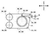
- This temporary storage part 12 is a temporary storage part of the system which clamps the both ends of a banknote with 1 set of tapes, respectively, using 2 sets of 1 set of tapes in a pair of upper and lower sides.
- FIG. 3 is a side view with the right side of the drawing as the front side and the left side of the drawing as the back side
- FIG. 4 is a perspective view with the right side of the drawing as the front side and the left side of the drawing as the back side.
- the temporary storage section 12 is provided with a drum rotation shaft 20 (FIG. 4) extending in the left-right direction at the center thereof, and a cylindrical drum 21 is fixed to the drum rotation shaft 20.
- an upper reel rotation shaft shaft 22 parallel to the drum rotation shaft shaft 20 is provided on the upper rear side of the drum rotation shaft shaft 20, and the drum is disposed on the lower rear side of the drum rotation shaft shaft 20 and below the upper reel rotation shaft shaft 22.
- a lower reel rotation shaft 23 parallel to the rotation shaft 20 is provided.
- the upper reel rotation shaft 22 has two upper tape reels 24L and 24R pivoted at predetermined locations in the axial direction (left-right direction) via upper reel torque limiters 25L and 25R, respectively. It is supported.
- the lower reel rotation shaft 23 has two lower tape reels 26L and 26R at predetermined positions at predetermined intervals in the axial direction (left and right direction), and lower reel torque limiters 27L and 27R, respectively. It is pivoted through.
- the interval in the axial direction (left-right direction) between the tape reels is set to be shorter than the length of the long side of the bill BL being conveyed.
- the upper tape reel 24L and the lower tape reel 26L are a pair of upper and lower tape reels arranged to face each other in the vertical direction, and the upper tape reel 24R and the lower tape reel 26R are also arranged to face each other in the vertical direction.
- the temporary storage unit 12 has a total of two sets of one set of tape reels, one set on the left and one set on the left and right.
- the left upper tape reel 24L and the lower tape reel 26L are referred to as the upper left tape reel 24L and the lower left tape reel 26L, respectively.
- the upper tape reel 24R and the lower tape reel 26R on the right side will be referred to as the upper right tape reel 24R and the lower right tape reel 26R, respectively.
- the left and right sets are appropriately distinguished by adding “left” or “right” to the names of the parts provided in total, that is, one set on each side.
- the temporary storage unit 12 pulls the upper left tape 28L forward from the upper left tape reel 24L, hangs it over the upper left tape roller 29L disposed on the front upper left side of the drum 21, and then the upper left tape reel 29L.
- the roller 29L is folded back and advanced to the left end of the upper end of the drum 21.
- the lower left tape 30L is pulled forward from the lower left tape reel 26L and is passed over the lower left first tape roller 31L arranged on the front lower left side of the drum 21, this lower side
- the first left tape roller 31L is used to move upward. Further, this is passed over the lower left second tape roller 32L disposed at a predetermined interval below the upper left tape roller 29L, and then folded back by the lower left second tape roller 32L to form a drum. 21 is advanced to the upper left part of the upper end.
- the upper left tape 28L and the lower left tape 30L are provided by a left pressing roller 33L disposed right above the upper left portion of the drum 21 so that the upper left tape 28L overlaps the lower left tape 30L.
- the upper end of the drum 21 is pressed to the left side, and each tip is fixed at a position on the left side of the peripheral side surface of the drum 21.
- the temporary storage unit 12 pulls the upper right tape 28R forward from the upper right tape reel 24R, hangs it on the upper right tape roller 29R disposed on the front upper right side of the drum 21, and then the upper right tape reel 29R.
- the tape roller 29 ⁇ / b> R is folded back to advance toward the right side of the upper end of the drum 21.
- the upper right tape 28R and the lower right tape 30R are drummed by a right pressing roller 33R arranged right above the upper right portion of the drum 21 so that the upper right tape 28R overlaps the lower right tape 30R. 21 is pressed to the right side of the upper end of the upper end 21, and each tip is fixed to the right side of the peripheral side surface of the drum 21.
- the temporary storage unit 12 has a total of two sets, one pair on the left and one on the right and left.
- the upper left tape 28L is placed at a predetermined position between the upper left tape reel 24L and the upper left tape roller 29L and at a predetermined position between the upper right tape reel 24R and the upper right tape roller 29R.
- an upper left tape position detection sensor 34R and an upper right tape position detection sensor 34R for detecting the position of the upper right tape 28R, respectively.
- a lower left tape position detection sensor 35L and a lower right tape position detection sensor 35R for detecting the positions of the side left tape 30L and the lower right tape 30R, respectively, are provided.
- drum rotation shaft shaft 20 of the temporary storage unit 12 has a drum rotation shaft gear 40 fixed to one end thereof, and is connected to the drum drive unit 41 via the drum rotation shaft gear 40.
- the drum 21 is rotated together with the drum rotation shaft 20 by transmitting the power from the drum drive unit 41 to the drum rotation shaft 20 through the drum rotation shaft gear 40.
- the drum drive unit 41 rotates the drum 21 in the winding direction by rotating the drum rotation shaft 20 in the winding direction that is counterclockwise in FIG.
- the drum 21 is rotated in the rewind direction by rotating the drum rotation shaft 20 in the rewind direction clockwise in the drawing.
- a drum rotation detection plate 42 is fixed at a predetermined position of the drum rotation shaft 20, and the rotation of the drum 21 is detected by detecting the rotation of the drum rotation detection plate 42 with the rotation detection sensor 43. Is supposed to be detected.
- a gear 44 is fixed to the other end of the drum rotating shaft 20, and the gear 44 is connected to the drive supply idle gear 45 by meshing with the drive supply idle gear 45. Further, the drive supply idle gear 45 is connected to the lower reel rotation shaft shaft gear 46 and is also connected to the upper reel rotation shaft shaft gear 48 via a rotation reversal gear 47.
- the lower reel rotation shaft shaft gear 46 rotates clockwise by transmitting the rotation as it is, while the upper reel rotation shaft gear.
- the rotation of the rotation 48 is reversed by the rotation reversal gear 47 and transmitted counterclockwise.
- the upper reel rotation shaft shaft gear 48 is pivotally supported on the other end of the upper reel rotation shaft shaft 22 via an upper one-way clutch 49, and the lower reel rotation shaft shaft gear 46 is supported by the lower reel rotation shaft shaft 23. Is pivotally supported by a lower one-way clutch 50.
- the upper one-way clutch 49 transmits the rotation to the upper reel rotation shaft shaft 22 only when the upper reel rotation shaft shaft gear 48 rotates in the counterclockwise direction in the drawing.
- One lower one-way clutch 50 transmits the rotation to the lower reel rotation shaft shaft 23 only when the lower reel rotation shaft shaft gear 46 rotates in the clockwise direction in the drawing. .
- the upper one-way clutch 49 and the lower one-way clutch 50 rotate only when the drum rotating shaft 20 rotates in the rewinding direction, which is clockwise in the drawing, and the upper reel rotating shaft 22 and the lower reel rotate. It is transmitted to the shaft 23.
- the upper reel torque limiters 25L and 25R are arranged along the upper reel rotation shaft shaft 22 from one side of the upper left tape reel 24L and the upper right tape reel 24R, respectively. It is provided so as to protrude to one end side of the 22.
- the upper reel torque limiters 25L and 25R have a double structure of an inner cylindrical inner ring 60 and an outer cylindrical outer ring 61.
- the inner ring 60 is fixed to the upper reel rotation shaft shaft 22 by a fixing pin 62, and a plurality of (for example, two) protrusions provided on the other end side of the outer ring 61.
- 63 is fitted in a recess 64 provided on one side surface of the upper left tape reel 24L and the upper right tape reel 24R.
- the outer ring 61 is fixed to the upper left tape reel 24L and the upper right tape reel 24R, respectively.
- the lower reel torque limiters 27L and 27R are respectively provided on one end side of the upper reel rotation shaft shaft 22 along the upper reel rotation shaft shaft 22 from one side surface of the lower left tape reel 26L and the lower right tape reel 26R. It is provided to protrude.
- the lower reel torque limiters 27L and 27R also have the same double structure, and the inner ring 60 is fixed to the lower reel rotation shaft 23 by a fixing pin 62 and provided at the other end of the outer ring 61.
- a plurality of (for example, two) protrusions 63 are fitted in recesses 64 provided on one side surface of the lower left tape reel 26L and the lower right tape reel 26R. Thereby, the outer ring 61 is fixed to the lower left tape reel 26L and the lower right tape reel 26R, respectively.
- the torque limiters 25L, 25R, 27L, and 27R absorb excessive torque between the inner ring 60 and the outer ring 61, respectively.
- the upper one-way clutch 49 is fitted between the upper reel rotation shaft shaft gear 48 and the upper reel rotation shaft shaft 22.
- the lower one-way clutch 50 is fitted between the lower reel rotation shaft shaft gear 46 and the lower reel rotation shaft shaft 23.
- the drum driving unit 41 when the drum driving unit 41 is driven to rotate the drum 21 in the rewinding direction, the power of the drum driving unit 41 is supplied to the upper reel rotating shaft shaft 22 and the lower reel. Also transmitted to the rotation shaft 23, the upper reel rotation shaft 22 and the lower reel rotation shaft 23 are rotated in the winding direction. Then, the upper left tape reel 24L and the upper right tape reel 24R, the lower left tape reel 26L and the lower right tape reel 26R are rotated in the winding direction.
- the upper left tape 28L and the upper right tape 28R are rewound from the drum 21 to the upper left tape reel 24L and the upper right tape reel 24R, and the lower left tape reel 26L and the lower right tape reel 26R from the drum 21.
- the lower left tape 30L and the lower right tape 30R are rewound.
- the temporary storage unit 12 rewinds each tape 28L, 28R, 30L, 30R from the drum 21 to each tape reel 24L, 24R, 26L, 26R.
- the gear 44 of the drum rotation shaft shaft 20 and the upper reel rotation shaft shaft gear 48 are higher than the speed at which the drum 21 rewinds the upper left tape 28L and the upper right tape 28R.
- the gear ratio is set so that 24R winds up the upper left tape 28L and the upper right tape 28R.
- the gear 44 of the drum rotation shaft shaft 20 and the lower reel rotation shaft shaft gear 46 have a lower left tape reel 26L than the speed at which the drum 21 rewinds the lower left tape 30L and the lower right tape 30R.
- the gear ratio is set so that the lower right tape reel 26R winds up the lower left tape 30L and the lower right tape 30R.
- the speed at which each tape reel 24L, 24R, 26L, 26R winds each tape 28L, 28R, 30L, 30R is higher than the speed at which the drum 21 rewinds each tape 28L, 28R, 30L, 30R.
- the speed at which the drum 21 rewinds each tape 28L, 28R, 30L, 30R make it faster.
- tension is applied to each tape 28L, 28R, 30L, 30R.
- the lower reel torque limiters 27L and 27R interposed between the lower reel rotating shaft 23, the lower left tape reel 26L and the lower right tape reel 26R are respectively connected to the lower left tape 30L and the lower tape tape L.
- the side right tape 30R operates so as not to be applied with a tension of a predetermined value or more (that is, a constant tension is always applied).
- each tape 28L, 28R is transferred from the drum 21 to each tape reel 24L, 24R, 26L, 26R with a constant tension applied to each tape 28L, 28R, 30L, 30R. , 30L, 30R can be rewound.
- the upper reel rotating shaft shaft 22 and the lower reel rotating shaft shaft 23 have a mechanism that rotates in the winding direction but does not rotate in the rewinding direction.
- the upper reel torque limiters 25L and 25R interposed between the upper reel rotation shaft shaft 22 and the upper left tape reel 24L and the upper right tape reel 24R rotate with respect to the upper reel rotation shaft shaft 22, respectively.
- lower reel torque limiters 27L and 27R interposed between the lower reel rotation shaft shaft 23, the lower left tape reel 26L and the lower right tape reel 26R respectively rotate with respect to the lower reel rotation shaft shaft 23. To do. Thereby, each tape reel 24L, 24R, 26L, 26R rotates in the rewind direction.
- the upper left tape 28L and the upper right tape 28R are wound around the drum 21 from the upper left tape reel 24L and the upper right tape reel 24R, and the drum 21 from the lower left tape reel 26L and the lower right tape reel 26R.
- the lower left tape 30L and the lower right tape 30R are wound up.
- the temporary storage unit 12 is configured to wind the tapes 28L, 28R, 30L, and 30R from the tape reels 24L, 24R, 26L, and 26R onto the drum 21.
- each tape 28L, 28R, 30L, 30R tension is applied to each tape 28L, 28R, 30L, 30R that applies a force in the rewinding direction to each tape reel 24L, 24R, 26L, 26R.
- the upper reel torque limiters 25L and 25R interposed between the upper reel rotation shaft 22 and the upper left tape reel 24L and the upper right tape reel 24R are respectively provided on the upper left tape 28L and the upper right tape 28R. It operates so that tension exceeding the value is not applied (that is, constant tension is always applied).
- the lower reel torque limiters 27L and 27R interposed between the lower reel rotating shaft 23, the lower left tape reel 26L and the lower right tape reel 26R are respectively connected to the lower left tape 30L and the lower tape tape L.
- the side right tape 30R operates so as not to be applied with a tension of a predetermined value or more (that is, a constant tension is always applied).
- the tapes 28L, 28R, 30L, 30R are always applied with a certain tension, and the tapes 28L, 28R are transferred from the tape reels 24L, 24R, 26L, 26R to the drum 21. , 30L, 30R can be wound up.
- the temporary storage unit 12 is provided with a transport roller shaft 70 parallel to the drum rotation shaft 20 in front of the lower left second tape roller 32L and the lower right second tape roller 32R.
- the transport roller shaft shaft 70 has two transport rollers 71L and 71R at a predetermined position in the axial direction (left and right direction) with a distance shorter than the length of the long side of the bill BL (length in the longitudinal direction of the bill). Is fixed.
- the conveyance roller shaft shaft 70 has a conveyance driving gear 72 fixed to one end thereof, and is connected to the conveyance driving unit 73 via the conveyance driving gear 72.
- the power by the transport driving unit 73 is transmitted to the transport rollers 71L and 71R via the transport roller shaft 70, whereby the transport rollers 71L and 71R rotate.
- the transport driving unit 73 rotates the transport rollers 71L and 71R in the storing direction by rotating the transport roller shaft shaft 70 in a counterclockwise direction in which the banknotes are stored (referred to as a storing direction). It is supposed to let you. Further, the transport driving unit 73 rotates the transport roller shafts 70 in the feeding direction by rotating the transporting roller shaft 70 in the clockwise direction in the drawing (referred to as the feeding direction). It has become.
- a conveyance rotation detection plate 74 is fixed at a predetermined position of the conveyance roller shaft shaft 70, and the rotation detection sensor 75 detects the rotation of the conveyance rotation detection plate 74 to detect the conveyance rollers 71 ⁇ / b> L and The rotation of 71R is detected.
- the temporary storage unit 12 rotates the transport rollers 71L and 71R (not shown in FIG. 7) in the storing direction, thereby allowing the bill BL to be transferred to the upper left tape roller 29L and the upper right tape roller 29R and to the lower left first. It feeds between the two tape rollers 32L and the lower right second tape roller 32R.
- the bills BL are fed in such a direction that the long side is perpendicular to the transport direction.
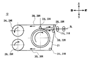
- the temporary storage unit 12 causes the drum drive unit 41 to rotate the drum 21 in the winding direction indicated by an arrow in the figure.
- the upper left tape reel 24L and the upper right tape are accompanied with the winding of the tapes 28L, 30L, 28R, 30R to the drum 21 side.
- the reel 24R rotates in the rewind direction indicated by the arrow in the drawing.
- the lower left tape reel 26L and the lower right tape reel 26R rotate in the rewind direction indicated by the arrows in the drawing.
- the left end which is one end portion in the longitudinal direction of the banknote BL to be fed, is sandwiched between the upper left tape 28L and the lower left tape 30L, and the right end of the banknote BL is sandwiched between the upper right tape 28R and the lower right tape 30R.
- the bills BL are wound around the drum 21 together with the tapes 28L, 30L, 28R, 30R.
- the temporary storage unit 12 stores the bill BL so as to be wound around the drum 21.
- the temporary storage unit 12 is configured to apply a certain tension to each tape 28L, 30L, 28R, 30R during storage. Thereby, the temporary storage part 12 can wind up and accommodate the banknote BL around the drum 21 while reliably holding the left and right ends of the banknote BL by the tapes 28L, 30L, 28R, and 30R.
- the temporary storage unit 12 causes the drum driving unit 41 to rotate the drum 21 in the rewinding direction indicated by the arrow in the drawing, and the winding direction in which the upper left tape reel 24L and the upper right tape reel 24R are indicated by the arrow in the drawing.
- the lower left tape reel 26L and the lower right tape reel 26R are rotated in the winding direction indicated by the arrows in the figure.
- the banknote BL wound around the drum 21 while being sandwiched between the tapes 28L, 30L, 28R, 30R is rewound from the drum 21 together with the tapes 28L, 30L, 28R, 30R.
- the conveyance roller in front from between the upper left tape roller 29L and upper right tape roller 29R and the lower left second tape roller 32L and lower right second tape roller 32R. It is sent out to 71L and 71R.
- the temporary storage unit 12 rotates the transport rollers 71L and 71R in the supply direction, whereby the banknote BL is supplied from the temporary storage unit 12.
- the temporary storage unit 12 pays out the bill BL.
- the temporary holding unit 12 applies a constant tension to each of the tapes 28L, 30L, 28R, and 30R even during feeding.
- the temporary storage part 12 can unwind and pay out the banknote BL from the drum 21 while reliably holding the left and right ends of the banknote BL by the tapes 28L, 30L, 28R, 30R.
- the winding diameter L when winding a banknote on the drum 21 is set to drum 21 by a banknote factor (thickness nonuniformity etc.). May become non-uniform at both axial ends.
- the amount of winding and rewinding of the tape per one rotation of the drum is different between the left and right pair of tapes 28L and 30L and the right and left pair of tapes 28R and 30R, respectively.
- the tape speed there is a difference in tape speed between a pair of upper and lower pairs of tapes.
- the torque limiters 25L, 25R, 27L, 27R that operate independently for the respective tape reels 24L, 24R, 26L, 26R. It was made to provide.
- each torque limiter 25L, 25R, 27L, 27R independently increases the tension of the tapes 28L, 28R, 30L, 30R between the tape reels 24L, 24R, 26L, 26R and the drum 21. Operates to keep constant at all times.
- the temporary storage part 12 can always keep the tension
- the temporary storage unit 12 can always keep the tension of all the tapes 28L, 28R, 30L, and 30R holding the bill BL constant, so that the holding stability of the bill is further improved as compared with the conventional case. Can be made.
- the temporary storage unit 12 always applies the tensions of all the tapes 28L, 28R, 30L, and 30R that hold the banknote BL, even in a situation where the difference in the winding diameter L is different between the both ends of the drum 21. Can be kept constant. For this reason, the temporary storage part 12 can improve the clamping stability of a banknote compared with the past, and it is more reliably that troubles, such as jam, will generate
- the second embodiment is an embodiment having a temporary holding unit having a configuration different from that of the temporary holding unit of the first embodiment. Therefore, only the configuration of the temporary holding unit will be described here.
- FIG. 11 A temporary holding unit 80 of the second embodiment is shown in FIG.
- the same parts as those of the temporary storage unit 12 of the first embodiment are denoted by the same reference numerals, and the description of the same parts will be omitted as appropriate.
- the temporary storage unit 80 is different in gear configuration from the temporary storage unit 12 of the first embodiment. That is, in the temporary storage unit 80, the winding driving gear 82 is pivotally supported on the other end of the drum rotation shaft 20 via the winding driving one-way clutch 81.
- the winding drive gear 82 is connected to the lower reel rotation shaft shaft first gear 84 via a drive connection idle gear 83. Further, the lower reel rotation shaft shaft first gear 84 is fixed to the other end of the lower reel rotation shaft shaft 23.
- a rewind drive gear 86 is pivotally supported on the drum rotation shaft 20 via a rewind drive one-way clutch 85 at a predetermined position between the rewind drive gear 82 and the drum 21.
- the rewinding drive gear 86 is connected to the drive supply idle gear 45. Further, the drive supply idle gear 45 is connected to the upper reel rotation shaft shaft gear 48 via a rotation reversal gear 47.
- the upper reel rotation shaft shaft gear 48 is fixed to the other end of the upper reel rotation shaft shaft 22.
- the drive supply idle gear 45 is fixed at a predetermined position between the lower reel rotation shaft shaft first gear 84 and the lower right tape reel 26R of the lower reel rotation shaft shaft 23.
- the shaft shaft second gear 87 is connected.
- the winding driving one-way clutch 81 transmits the rotation to the winding driving gear 82 only when the drum rotating shaft 20 rotates in the winding direction counterclockwise in the drawing.
- the rewind drive one-way clutch 85 transmits the rotation to the rewind drive gear 86 only when the drum rotation shaft 20 rotates in the rewind direction clockwise in the drawing.
- the drum driving unit 41 rotates the drum 21 in the winding direction
- the rotation is driven by the winding driving gear 82, the drive coupling idle gear 83, and the lower reel rotation shaft shaft.
- the lower reel rotation axis shaft 23 is rotated in the rewind direction.
- the lower reel rotation shaft shaft 23 is rotated by rotating the lower reel rotation shaft shaft second gear 87, the drive supply idle gear 45, the rotation reversing gear 47, and the upper reel rotation shaft shaft.
- the upper reel rotating shaft shaft 22 is also rotated in the rewinding direction.
- the upper left tape 28L and the upper right tape 28R are wound from the upper left tape reel 24L and the upper right tape reel 24R to the drum 21.
- the lower left tape 30L and the lower right tape 30R are wound around the drum 21 from the lower left tape reel 26L and the lower right tape reel 26R.
- the temporary storage unit 80 winds the tapes 28L, 28R, 30L, and 30R from the tape reels 24L, 24R, 26L, and 26R onto the drum 21.
- the winding drive gear 82 and the upper reel rotation shaft shaft gear 48 are configured so that the upper left tape reel 24L and the upper right tape reel 24R are faster than the speed at which the drum 21 winds the upper left tape 28L and the upper right tape 28R.
- the gear ratio is set so that the speed at which the upper left tape 28L and the upper right tape 28R are rewound is slower.
- the winding drive gear 82 and the lower reel rotation shaft shaft first gear 84 have a lower left tape reel 26L than the speed at which the drum 21 winds the lower left tape 30L and the lower right tape 30R.
- the gear ratio is set so that the lower right tape reel 26R rewinds the lower left tape 30L and the lower right tape 30R.
- each tape reel 24L, 24R, 26L, 26R rewinds each tape 28L, 28R, 30L, 30R is faster than the speed at which the drum 21 winds each tape 28L, 28R, 30L, 30R.
- tension is applied to each tape 28L, 28R, 30L, 30R.
- the lower reel torque limiters 27L and 27R interposed between the lower reel rotating shaft 23, the lower left tape reel 26L and the lower right tape reel 26R are respectively connected to the lower left tape 30L and the lower tape tape L.
- the side right tape 30R operates so as not to be applied with a tension of a predetermined value or more (that is, a constant tension is always applied).
- the tapes 28L, 28R, 30L, 30R are always applied with a constant tension, and the tapes 28L, 28R are transferred from the tape reels 24L, 24R, 26L, 26R to the drum 21. , 30L, 30R can be wound up.
- the temporary storage unit 80 rotates the rewind drive gear 86, the drive supply idle gear 45, and the lower reel.
- the lower reel rotation shaft shaft 23 is rotated in the winding direction.
- the rotation by the drum driving unit 41 is caused to rotate upward via the rewinding drive gear 86, the drive supply idle gear 45, the rotation reversing gear 47, and the upper reel rotation shaft shaft gear 48.
- the upper reel rotation shaft 22 is also rotated in the winding direction.
- the upper left tape 28L and the upper right tape 28R are rewound from the drum 21 to the upper left tape reel 24L and the upper right tape reel 24R.
- the lower left tape 30L and the lower right tape 30R are rewound from the drum 21 to the lower left tape reel 26L and the lower right tape reel 26R.
- the temporary storage unit 80 rewinds each tape 28L, 28R, 30L, 30R from the drum 21 to each tape reel 24L, 24R, 26L, 26R.
- the rewinding drive gear 86 and the upper reel rotation shaft shaft gear 48 allow the upper left tape reel 24L and the upper right tape reel 24R to be faster than the speed at which the drum 21 rewinds the upper left tape 28L and the upper right tape 28R.
- the gear ratio is set so that the speed at which the upper left tape 28L and the upper right tape 28R are wound is higher.
- the rewinding drive gear 82 and the lower reel rotation shaft shaft second gear 87 are lower than the speed at which the drum 21 rewinds the lower left tape 30L and the lower right tape 30R.
- the gear ratio is set so that the speed at which the 26L and the lower right tape reel 26R winds the lower left tape 30L and the lower right tape 30R is higher.
- the speed at which each tape reel 24L, 24R, 26L, 26R winds each tape 28L, 28R, 30L, 30R is higher than the speed at which the drum 21 rewinds each tape 28L, 28R, 30L, 30R.
- the speed at which the drum 21 rewinds each tape 28L, 28R, 30L, 30R make it faster.
- tension is applied to each tape 28L, 28R, 30L, 30R.
- the lower reel torque limiters 27L and 27R interposed between the lower reel rotating shaft shaft 23, the lower left tape reel 26L and the lower right tape reel 26R are respectively connected to the lower left tape 30L and the lower reel tape 30L.
- the lower right tape 30R is operated so as not to apply a tension equal to or higher than a predetermined value (that is, a constant tension is always applied).
- the tapes 28L, 28R, 30L, 30R are always applied with a certain tension, and the tapes 28L, 28R are transferred from the drum 21 to the tape reels 24L, 24R, 26L, 26R. , 30L, 30R can be rewound.
- the temporary storage unit 80 stores and feeds the bills BL by winding and rewinding the tapes 28L, 28R, 30L, and 30R.
- the torque limiters 25L, 25R, 27L, and 27R are respectively independent of the tapes 28L, 28R, and 30L between the tape reels 24L, 24R, 26L, and 26R and the drum 21.
- 30R operates so as to always keep the tension constant. For this reason, the tensions of all the tapes 28L, 28R, 30L, and 30R in each set can always be kept constant regardless of the difference in tape speed between the pair of upper and lower pairs of tapes.
- the upper reel torque limiters 25L and 25R are respectively connected from one side of the upper left tape reel 24L and the upper right tape reel 24R. It provided so that it might protrude in the one end side of the upper reel rotating shaft shaft 22.
- the lower reel torque limiters 27L and 27R were also provided so as to protrude from one side of the lower left tape reel 26L and the lower right tape reel 26R to one end of the upper reel rotation shaft 22 respectively.
- each torque limiter 25L, 25R, 27L, 27R is provided so as to protrude from one side surface of each tape reel 24L, 24R, 26L, 26R to one end side in the axial direction.
- the upper reel torque limiters 25L and 25R may be provided between the upper left tape reel 24L and the upper right tape reel 24R, respectively.
- the lower reel torque limiters 27L and 27R may be provided between the lower left tape reel 26L and the lower right tape reel 26R, respectively.
- the upper reel torque limiter 25L and the lower reel torque limiter 27L are opposite to the first embodiment, respectively, on the other inner surfaces of the upper right tape reel 24R and the lower right tape reel 26R. On the other hand, it attaches so that it may protrude to the other end side of an axial direction.
- the upper reel torque limiters 25L and 25R are arranged between the upper left tape reel 24L and the upper right tape reel 24R, and the lower reel torque limiters 27L and 27R are connected to the lower left tape reel 26L and It is arranged between the lower right tape reel 26R.
- spaces are created outside the upper left tape reel 24L and the upper right tape reel 24R and outside the lower left tape reel 26L and the lower right tape reel 26R. For this reason, by effectively utilizing this outer space, for example, the width of the housing of the temporary storage unit 12 or 80 can be reduced and the size can be reduced.
- the present invention is not limited to this, and the present invention may be applied to a so-called downward take-up type temporary holding portion in which a banknote held between two pairs of upper and lower tapes is taken up and taken in from the lower end portion of the drum.
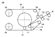
- FIG. 13 shows such a temporary holding unit 100 of the downward capturing method.
- the upper tape 103 is drawn forward from the upper tape reel 102 disposed on the upper rear side of the cylindrical drum 101, and the upper first tape roller 104 disposed on the upper front side of the drum 101. Hang over. Thereafter, the upper tape 103 is moved downward by the upper first tape roller 104 and is further folded back by the upper second tape roller 105 disposed below the upper first tape roller 104 to the lower end of the drum 101. And proceed.
- the lower tape 107 is pulled forward from the lower tape reel 106 disposed on the lower rear side of the drum 101, and this is lowered to the lower first tape roller 108 disposed on the lower front side of the drum 101. Hang over. Thereafter, the lower tape 107 is moved forward and obliquely upward by the lower first tape roller 105A, and the lower second tape roller 109 disposed at a predetermined interval below the upper second tape roller 105. Hang over. Thereafter, the lower tape 107 is folded back by the lower second tape roller 109 and advanced to the lower end of the drum 101.
- the upper tape 103 and the lower tape 107 include a first pressing roller 110 disposed on the front side of the lower end portion of the drum 101 so that the upper tape 103 overlaps the lower tape 107, and the drum 101. It is pressed against the lower end portion of the drum 101 by the second pressing roller 111 disposed immediately below the lower end portion, and the respective leading end portions are fixed to the peripheral side surface of the drum 101.
- the roller 108, the lower second tape roller 109, the first pressing roller 110, and the second pressing roller 111 are provided in two sets of left and right.
- the temporary storage unit 100 rotates the drum 101 in the winding direction that is clockwise in the drawing, so that the upper tape 103 and the lower tape 107 are transferred from the upper tape reel 102 and the lower tape reel 106 to the drum 101. It is designed to wind up.
- the upper tape 103 and the lower tape 107 are rewound from the drum 101 to the upper tape reel 102 and the lower tape reel 106 by rotating the drum 101 in the rewind direction counterclockwise in the drawing. It has become.
- the downward take-in type temporary storage unit 100 has such a configuration, and when the banknote is stored, the banknote BL transported via the plurality of transport rollers 112 arranged in front is lower than the upper second tape roller 105. It is fed to the side second tape roller 109. At this time, the temporary storage unit 100 rotates the drum 101 in the winding direction, and rotates the upper tape reel 102 and the lower tape reel 106 in the rewinding direction, so that the two sets of left and right upper tapes 103 are transferred to the banknote BL. And the banknote BL is accommodated by pinching with the lower tape 107, and winding up to the drum 101.
- the temporary storage unit 100 rotates the drum 101 in the rewinding direction and rotates the upper tape reel 102 and the lower tape reel 106 in the winding direction so that two sets of the upper and lower tapes 103 and The bill BL is rewound from the drum 101 together with the lower tape 107.
- the temporary storage part 100 pays out the bill BL from between the upper second tape roller 105 and the lower second tape roller 109.
- the temporary storage unit 100 of the downward taking-in system stores and feeds the bills BL.
- the torque limiter 25L is used as a torque control unit that controls the torque between the tape reels 24L, 24R, 26L, and 26R and the reel rotation shafts 22 and 23. 25R, 27L, and 27R.
- the present invention is not limited to this, and another mechanism that functions similarly to the torque limiters 25L, 25R, 27L, and 27R may be used instead of the torque limiters 25L, 25R, 27L, and 27R.
- the one-way clutches 49 and 50 are used as the rotation direction control unit that restricts the rotation direction of the reel rotation shafts 22 and 23.
- the one-way clutch 49 is not limited to this.
- 50 may be used in place of the one-way clutches 49, 50.
- a mechanism that functions similarly to the one-way clutches 81 and 85 may be used instead of the one-way clutches 81 and 85.
- the present invention is applied to the temporary storage units 12 and 80 as the medium storage and feeding device of the banknote depositing and dispensing machine 4 provided in the ATM 1, but the present invention is not limited thereto. As long as it is a drum winding type medium storage and feeding device, it may be applied to devices other than the temporary storage units 12 and 80, and can also be applied. Further, as a device other than the temporary storage units 12 and 80, the present invention may be applied to a medium storage and feeding device that handles media other than banknotes (for example, tickets, tickets, paper, etc.).
- the present invention is applied to the ATM 1 as the medium processing apparatus.
- the present invention is not limited to this, and any medium processing apparatus having a drum winding type temporary storage unit may be used. May apply and can also apply.
- the present invention can be widely used in an apparatus such as an ATM that handles banknotes. (Explanation of symbols)
Landscapes
- Engineering & Computer Science (AREA)
- Mechanical Engineering (AREA)
- Physics & Mathematics (AREA)
- General Physics & Mathematics (AREA)
- Discharge By Other Means (AREA)
- Winding Of Webs (AREA)
- Delivering By Means Of Belts And Rollers (AREA)
- Controlling Rewinding, Feeding, Winding, Or Abnormalities Of Webs (AREA)
- Impression-Transfer Materials And Handling Thereof (AREA)
Description
[1-1.現金自動預払機の構成]
まず第1の実施の形態から説明する。図1に、現金自動預払機(ATM)1の全体構成の概略を示す。
次に、図2を用いて、紙幣入出金機4の内部構成について説明する。尚、この図2は、図右側を前側、図左側を後側とした側面図である。
次に、図3及び図4を用いて、一時保留部12の構成について説明する。この一時保留部12は、上下1対で1組のテープを2組用いて紙幣の両端部分をそれぞれ1組のテープで挟持する方式の一時保留部である。
ここで、紙幣BLを一時保留部12に収納するときの動作、及び紙幣BLを一時保留部12から繰り出すときの動作について説明する。
る。
次に、第2の実施の形態について説明する。この第2の実施の形態は、第1の実施の形態の一時保留部とは異なる構成の一時保留部を有する実施の形態である。よって、ここでは一時保留部の構成についてのみ説明することとする。
この第2の実施の形態の一時保留部80を、図11に示す。この図11に示す一時保留部80には、第1の実施の形態の一時保留部12との同一部分に同一符号を付しており、同一部分の説明については適宜省略する。
[3-1.他の実施の形態1]
尚、上述した第1及び第2の実施の形態では、図5に示したように、上側リール用トルクリミッタ25L及び25Rを、それぞれ上側左テープリール24L及び上側右テープリール24Rの一側面から、上側リール回転軸シャフト22の一端側に突出するように設けた。
また、上述した第1及び第2の実施の形態では、図3に示したように、上下1対のテープ2組で挟持した紙幣をドラムの上端部分から巻き取って取り込んでいく所謂上方取り込み方式の一時保留部12及び80に本発明を適用するようにした。
さらに、上述した第1及び第2の実施の形態では、一時保留部12及び80に、上下1対で1組のテープを2組設けるようにしたが、これに限らず、3組以上設けるようにしてもよい。
さらに、上述した第1及び第2の実施の形態では、各テープリール24L、24R、26L、26Rと、リール回転軸シャフト22、23との間のトルクを制御するトルク制御部として、トルクリミッタ25L、25R、27L、27Rを用いるようにした。しかし、これに限らず、トルクリミッタ25L、25R、27L、27Rと同様に機能する別の機構を、トルクリミッタ25L、25R、27L、27Rの代わりに用いるようにしてもよい。
さらに、上述した第1の実施の形態では、リール回転軸シャフト22、23の回転方向を制限する回転方向制御部としてワンウェイクラッチ49、50を用いるようにしたが、これに限らず、ワンウェイクラッチ49、50と同様に機能する別の機構を、ワンウェイクラッチ49、50の代わりに用いるようにしてもよい。
さらに、上述した第1及び第2の実施の形態では、本発明を、ATM1に設けられた紙幣入出金機4の媒体収納繰出装置としての一時保留部12、80に適用したが、これに限らず、ドラム巻付型の媒体収納繰出装置であれば、一時保留部12、80以外の装置に適用してもよく、また適用することができる。また、一時保留部12、80以外の装置として、紙幣以外の媒体(例えば、チケット、切符、紙など)を扱う媒体収納繰出装置に適用してもよい。
さらに、本発明は、上述した実施の形態と、上述した他の実施の形態とに限定されるものではない。すなわち本発明は、上述した実施の形態と上述した他の実施の形態の一部または全部を任意に組み合わせた実施の形態や、一部を抽出した実施の形態にもその適用範囲が及ぶものである。
(産業上の利用可能性)
(符号の説明)
4……紙幣入出金機、
12、80、100、200……一次保留部、
20……ドラム回転軸シャフト、
21、101、201……ドラム、
22、23……リール回転軸シャフト、
24L、24R、26L、26R、102、106、202、203……テープリール、
25L、25R、27L、27R……トルクリミッタ、
28L、28R、30L、30R、103、107、204、205……テープ、
49、50、81、85……ワンウェイクラッチ。
Claims (5)
- 2本1組で媒体を挟持するテープをテープリールとドラムとの間で巻き取る又は巻き戻すことで媒体を収納又は繰り出す媒体収納繰出装置において、
複数組のテープと、
上記複数組のテープのそれぞれを巻き取る複数組のテープリールと、
上記テープリールの回転軸であり、各組の一方のテープリールと他方のテープリールとで別々に設けられる2本のリール回転軸シャフトと、
上記複数組のテープにより挟持された媒体を上記複数組のテープと共に巻き取るドラムと、
上記テープリールごとに独立して設けられ、各テープリールと上記ドラムとの間で各テープの張力が一定となるように、各テープリールと上記リール軸シャフトとの間のトルク制御を行うトルク制御部と、
を有する媒体収納繰出装置。 - 上記ドラムの回転軸であるドラム回転軸シャフトと、上記2本のリール回転軸シャフトは、それぞれ複数のギアにより連結され、
上記複数のギアは、上記ドラムから上記テープが巻き戻される速度より、上記テープリールに上記テープが巻き取られる速度の方が速くなるようにギア比が設定され、
さらに上記ドラム回転軸シャフトと、上記2本のリール回転軸シャフトのそれぞれとの間に設けられ、上記回転軸シャフトの回転方向がドラムを巻き戻す方向の回転方向である場合にのみ、その回転を上記複数のギアを介して上記2本のリール回転軸シャフトに伝達する回転方向制御部を有する
請求項1に記載の媒体収納繰出装置。 - 上記ドラムの回転軸であるドラム回転軸シャフトと、上記2本のリール回転軸シャフトは、それぞれ巻き取り時用の複数のギアと、巻き戻し時用の複数のギアとにより連結され、
上記巻き取り時用の複数のギアは、上記ドラムが上記テープを巻き取る速度より、上記テープリールから上記テープが巻き戻される速度の方が遅くなるようにギア比が設定され、
上記巻き戻し時用の複数のギアは、上記ドラムから上記テープが巻き戻される速度より、上記テープリールに上記テープが巻き取られる速度の方が速くなるようにギア比が設定され、
さらに、上記ドラム回転軸シャフトと、上記2本のリール回転軸シャフトのそれぞれとの間に設けられ、上記回転軸シャフトの回転方向がドラムを巻き取る方向の回転方向である場合にのみ、その回転を上記巻き取り時用の複数のギアを介して上記2本のリール回転軸シャフトに伝達する巻き取り駆動用の回転方向制御部と、
上記ドラム回転軸シャフトと、上記2本のリール回転軸シャフトのそれぞれとの間に設けられ、上記回転軸シャフトの回転方向がドラムを巻き戻す方向の回転方向である場合にのみ、その回転を上記巻き戻し時用の複数のギアを介して上記2本のリール回転軸シャフトに伝達する巻き戻し時駆動用の回転方向制御部と、
を有する請求項1に記載の媒体収納繰出装置。 - 上記テープは2組でなり、
上記2本のリール回転軸シャフトには、それぞれ一方の組のテープリールと、他方の組のテープリールとが所定の間隔を隔てて枢支され、
上記トルク制御部は、上記一方の組のテープリールと他方の組のテープリールの間のスペースに配置される
請求項2に記載の媒体収納繰出装置。 - 媒体を鑑別する鑑別部と、
上記鑑別部により鑑別された媒体を一時的に収納する一時保留部と、
上記一時保留部から繰り出される媒体を収納する紙幣収納庫と
を有し、
上記一時保留部は、
2本1組で媒体を挟持するテープをテープリールとドラムとの間で巻き取る又は巻き戻すことで媒体を収納又は繰り出すドラム巻付型であり、複数組のテープと、上記複数組のテープのそれぞれを巻き取る複数組のテープリールと、上記テープリールの回転軸であり、各組の一方のテープリールと他方のテープリールとで別々に設けられる2本のリール回転軸シャフトと、上記複数組のテープにより挟持された媒体を上記複数組のテープと共に巻き取るドラムと、上記テープリールごとに独立して設けられ、各テープリールと上記ドラムとの間で各テープの張力が一定となるように、各テープリールと上記リール軸シャフトとの間のトルク制御を行うトルク制御部とを有する媒体処理装置。
Priority Applications (4)
| Application Number | Priority Date | Filing Date | Title |
|---|---|---|---|
| BR112013022274-3A BR112013022274B1 (pt) | 2012-03-26 | 2012-12-03 | Dispositivo de armazenamento e alimentação de meio e dispositivo de processamento de meio |
| RU2013140183/08A RU2542899C1 (ru) | 2012-03-26 | 2012-12-03 | Устройство сохранения и выдачи носителей и устройство обработки носителей |
| CN201280010953.5A CN103429514B (zh) | 2012-03-26 | 2012-12-03 | 介质收纳送出装置和介质处理装置 |
| US14/002,360 US9016457B2 (en) | 2012-03-26 | 2012-12-03 | Medium storage and feeding device and medium processing device |
Applications Claiming Priority (2)
| Application Number | Priority Date | Filing Date | Title |
|---|---|---|---|
| JP2012-069688 | 2012-03-26 | ||
| JP2012069688A JP6083943B2 (ja) | 2012-03-26 | 2012-03-26 | 媒体収納繰出装置及び媒体処理装置 |
Publications (1)
| Publication Number | Publication Date |
|---|---|
| WO2013145449A1 true WO2013145449A1 (ja) | 2013-10-03 |
Family
ID=49258782
Family Applications (1)
| Application Number | Title | Priority Date | Filing Date |
|---|---|---|---|
| PCT/JP2012/081295 Ceased WO2013145449A1 (ja) | 2012-03-26 | 2012-12-03 | 媒体収納繰出装置及び媒体処理装置 |
Country Status (7)
| Country | Link |
|---|---|
| US (1) | US9016457B2 (ja) |
| JP (1) | JP6083943B2 (ja) |
| CN (1) | CN103429514B (ja) |
| BR (1) | BR112013022274B1 (ja) |
| MY (1) | MY163435A (ja) |
| RU (1) | RU2542899C1 (ja) |
| WO (1) | WO2013145449A1 (ja) |
Cited By (1)
| Publication number | Priority date | Publication date | Assignee | Title |
|---|---|---|---|---|
| WO2018061149A1 (ja) * | 2016-09-29 | 2018-04-05 | 富士通フロンテック株式会社 | 紙葉類収容装置及び紙葉類収容方法 |
Families Citing this family (17)
| Publication number | Priority date | Publication date | Assignee | Title |
|---|---|---|---|---|
| CN103676990B (zh) * | 2013-12-30 | 2016-12-07 | 广州广电运通金融电子股份有限公司 | 纸币暂存模块和其卷筒转速控制方法以及自动柜员机 |
| KR101628472B1 (ko) * | 2014-08-20 | 2016-06-09 | 노틸러스효성 주식회사 | 지폐 수납 방출 장치 |
| CN107108145B (zh) * | 2015-01-09 | 2019-07-23 | 富士通先端科技株式会社 | 纸张收容装置和纸张收容方法 |
| CN104637156B (zh) * | 2015-03-06 | 2017-05-24 | 广州广电运通金融电子股份有限公司 | 纸币转出控制方法、装置以及纸币存储设备 |
| KR102323433B1 (ko) * | 2015-05-28 | 2021-11-09 | 효성티앤에스 주식회사 | 매체 수납 방출 장치 및 이를 포함하는 매체 처리 장치 |
| CN104952146B (zh) * | 2015-06-05 | 2017-09-29 | 深圳怡化电脑股份有限公司 | 卡固结构、暂存机构及自动存取款机 |
| WO2017126129A1 (ja) * | 2016-01-22 | 2017-07-27 | 富士通フロンテック株式会社 | 紙葉類収納機構及びその制御方法 |
| WO2017203715A1 (ja) | 2016-05-27 | 2017-11-30 | 富士通フロンテック株式会社 | 紙葉類収容装置及び紙葉類収容装置の制御方法 |
| US10665064B2 (en) | 2016-07-13 | 2020-05-26 | Deibold Nixdorf, Incorporated | Single continuous belt in an escrow subassembly |
| CN107230278B (zh) * | 2017-07-17 | 2023-08-11 | 深圳怡化电脑股份有限公司 | 介质收纳送出装置及系统 |
| CN107195074A (zh) * | 2017-07-17 | 2017-09-22 | 深圳怡化电脑股份有限公司 | 介质输送装置及系统 |
| CN107369247B (zh) * | 2017-08-30 | 2023-05-30 | 深圳怡化电脑股份有限公司 | 介质收集装置及介质交易装置 |
| JP6450041B1 (ja) * | 2018-03-23 | 2019-01-09 | 日本金銭機械株式会社 | 駆動伝達切替え機構、紙葉収納部、及び紙葉処理装置 |
| JP2019167232A (ja) | 2018-03-26 | 2019-10-03 | グローリー株式会社 | 紙葉類収納装置および紙葉類処理機 |
| EP3809381B1 (en) | 2018-07-17 | 2024-09-04 | Glory Ltd. | Paper sheet storage device |
| JP7284013B2 (ja) * | 2018-09-13 | 2023-05-30 | グローリー株式会社 | 紙葉類収納装置、及び、紙葉類処理装置 |
| JP2020071823A (ja) | 2018-11-02 | 2020-05-07 | グローリー株式会社 | 紙葉類収納装置、及び、紙葉類処理装置 |
Citations (3)
| Publication number | Priority date | Publication date | Assignee | Title |
|---|---|---|---|---|
| JP2005505068A (ja) * | 2001-09-28 | 2005-02-17 | キャッシュコード カンパニー インコーポレーテッド | 紙幣アキュムレータ |
| JP2009107824A (ja) * | 2007-10-31 | 2009-05-21 | Oki Electric Ind Co Ltd | 媒体収納繰出装置 |
| JP2010006494A (ja) * | 2008-06-24 | 2010-01-14 | Oki Electric Ind Co Ltd | 媒体収納繰出装置 |
Family Cites Families (3)
| Publication number | Priority date | Publication date | Assignee | Title |
|---|---|---|---|---|
| CH675873A5 (ja) * | 1987-07-02 | 1990-11-15 | Ferag Ag | |
| SE463283B (sv) * | 1989-07-20 | 1990-10-29 | Inter Innovation Ab | Anordning foer inmatning av vaerdepapper, saasom sedlar, checker etc |
| CA2299827C (en) * | 2000-03-02 | 2009-12-15 | Cashcode Company Inc. | Combination banknote validator and banknote dispenser |
-
2012
- 2012-03-26 JP JP2012069688A patent/JP6083943B2/ja active Active
- 2012-12-03 MY MYPI2013701508A patent/MY163435A/en unknown
- 2012-12-03 US US14/002,360 patent/US9016457B2/en active Active
- 2012-12-03 CN CN201280010953.5A patent/CN103429514B/zh active Active
- 2012-12-03 BR BR112013022274-3A patent/BR112013022274B1/pt active IP Right Grant
- 2012-12-03 WO PCT/JP2012/081295 patent/WO2013145449A1/ja not_active Ceased
- 2012-12-03 RU RU2013140183/08A patent/RU2542899C1/ru active
Patent Citations (3)
| Publication number | Priority date | Publication date | Assignee | Title |
|---|---|---|---|---|
| JP2005505068A (ja) * | 2001-09-28 | 2005-02-17 | キャッシュコード カンパニー インコーポレーテッド | 紙幣アキュムレータ |
| JP2009107824A (ja) * | 2007-10-31 | 2009-05-21 | Oki Electric Ind Co Ltd | 媒体収納繰出装置 |
| JP2010006494A (ja) * | 2008-06-24 | 2010-01-14 | Oki Electric Ind Co Ltd | 媒体収納繰出装置 |
Cited By (2)
| Publication number | Priority date | Publication date | Assignee | Title |
|---|---|---|---|---|
| WO2018061149A1 (ja) * | 2016-09-29 | 2018-04-05 | 富士通フロンテック株式会社 | 紙葉類収容装置及び紙葉類収容方法 |
| US10662016B2 (en) | 2016-09-29 | 2020-05-26 | Fujitsu Frontech Limited | Paper sheet accommodating apparatus and paper sheet accommodating method |
Also Published As
| Publication number | Publication date |
|---|---|
| JP2013199365A (ja) | 2013-10-03 |
| RU2542899C1 (ru) | 2015-02-27 |
| RU2013140183A (ru) | 2015-03-10 |
| US9016457B2 (en) | 2015-04-28 |
| US20140090949A1 (en) | 2014-04-03 |
| MY163435A (en) | 2017-09-15 |
| BR112013022274A2 (pt) | 2016-12-06 |
| CN103429514A (zh) | 2013-12-04 |
| CN103429514B (zh) | 2016-09-28 |
| JP6083943B2 (ja) | 2017-02-22 |
| BR112013022274B1 (pt) | 2020-12-15 |
Similar Documents
| Publication | Publication Date | Title |
|---|---|---|
| JP6083943B2 (ja) | 媒体収納繰出装置及び媒体処理装置 | |
| JP5704027B2 (ja) | 媒体処理装置及び媒体取引装置 | |
| CN103548062B (zh) | 介质收纳送出装置 | |
| CN104093654B (zh) | 介质收纳送出装置以及介质交易装置 | |
| CN105873842B (zh) | 介质处理装置和介质交易装置 | |
| CN104854629B (zh) | 介质处理装置和介质交易装置 | |
| JP5935512B2 (ja) | 媒体処理装置及び媒体取引装置 | |
| JP6582544B2 (ja) | 媒体処理装置及び媒体取引装置 | |
| JP6070326B2 (ja) | 紙葉類収納繰出し装置及び紙葉類取扱装置 | |
| CN104094325B (zh) | 介质处理装置 | |
| JP2018184289A (ja) | 媒体処理装置及び自動取引装置 | |
| JP7067191B2 (ja) | 媒体収納繰出装置及び媒体取引装置 | |
| WO2016059824A1 (ja) | 媒体集積装置及び媒体取引装置 | |
| KR20150124632A (ko) | 환류식 입출금기의 환류카세트 | |
| WO2015178198A1 (ja) | 媒体収納装置及び媒体取引装置 | |
| JP5927909B2 (ja) | 紙葉類搬送装置及び紙葉類取扱装置 | |
| JP3036267B2 (ja) | 貨幣取扱装置 | |
| JP7354665B2 (ja) | 媒体処理装置及び媒体取引装置 | |
| JP4566813B2 (ja) | 紙幣結束機 | |
| JP2021047718A (ja) | 媒体処理装置及び媒体取引装置 | |
| JP2019139318A (ja) | 媒体処理装置及び媒体取引装置 |
Legal Events
| Date | Code | Title | Description |
|---|---|---|---|
| ENP | Entry into the national phase |
Ref document number: 2013140183 Country of ref document: RU Kind code of ref document: A |
|
| WWE | Wipo information: entry into national phase |
Ref document number: 14002360 Country of ref document: US |
|
| 121 | Ep: the epo has been informed by wipo that ep was designated in this application |
Ref document number: 12872438 Country of ref document: EP Kind code of ref document: A1 |
|
| REG | Reference to national code |
Ref country code: BR Ref legal event code: B01A Ref document number: 112013022274 Country of ref document: BR |
|
| NENP | Non-entry into the national phase |
Ref country code: DE |
|
| 122 | Ep: pct application non-entry in european phase |
Ref document number: 12872438 Country of ref document: EP Kind code of ref document: A1 |
|
| ENP | Entry into the national phase |
Ref document number: 112013022274 Country of ref document: BR Kind code of ref document: A2 Effective date: 20130830 |