WO2013128945A1 - Procédé d'impression à jet d'encre - Google Patents
Procédé d'impression à jet d'encre Download PDFInfo
- Publication number
- WO2013128945A1 WO2013128945A1 PCT/JP2013/001281 JP2013001281W WO2013128945A1 WO 2013128945 A1 WO2013128945 A1 WO 2013128945A1 JP 2013001281 W JP2013001281 W JP 2013001281W WO 2013128945 A1 WO2013128945 A1 WO 2013128945A1
- Authority
- WO
- WIPO (PCT)
- Prior art keywords
- ink
- inkjet
- temperature
- recording head
- tank
- Prior art date
Links
Images

Classifications
-
- B—PERFORMING OPERATIONS; TRANSPORTING
- B41—PRINTING; LINING MACHINES; TYPEWRITERS; STAMPS
- B41J—TYPEWRITERS; SELECTIVE PRINTING MECHANISMS, i.e. MECHANISMS PRINTING OTHERWISE THAN FROM A FORME; CORRECTION OF TYPOGRAPHICAL ERRORS
- B41J2/00—Typewriters or selective printing mechanisms characterised by the printing or marking process for which they are designed
- B41J2/005—Typewriters or selective printing mechanisms characterised by the printing or marking process for which they are designed characterised by bringing liquid or particles selectively into contact with a printing material
- B41J2/01—Ink jet
- B41J2/17—Ink jet characterised by ink handling
- B41J2/175—Ink supply systems ; Circuit parts therefor
-
- B—PERFORMING OPERATIONS; TRANSPORTING
- B41—PRINTING; LINING MACHINES; TYPEWRITERS; STAMPS
- B41J—TYPEWRITERS; SELECTIVE PRINTING MECHANISMS, i.e. MECHANISMS PRINTING OTHERWISE THAN FROM A FORME; CORRECTION OF TYPOGRAPHICAL ERRORS
- B41J2/00—Typewriters or selective printing mechanisms characterised by the printing or marking process for which they are designed
- B41J2/005—Typewriters or selective printing mechanisms characterised by the printing or marking process for which they are designed characterised by bringing liquid or particles selectively into contact with a printing material
- B41J2/01—Ink jet
- B41J2/135—Nozzles
- B41J2/14—Structure thereof only for on-demand ink jet heads
- B41J2/14201—Structure of print heads with piezoelectric elements
-
- B—PERFORMING OPERATIONS; TRANSPORTING
- B41—PRINTING; LINING MACHINES; TYPEWRITERS; STAMPS
- B41J—TYPEWRITERS; SELECTIVE PRINTING MECHANISMS, i.e. MECHANISMS PRINTING OTHERWISE THAN FROM A FORME; CORRECTION OF TYPOGRAPHICAL ERRORS
- B41J2202/00—Embodiments of or processes related to ink-jet or thermal heads
- B41J2202/01—Embodiments of or processes related to ink-jet heads
- B41J2202/12—Embodiments of or processes related to ink-jet heads with ink circulating through the whole print head
-
- B—PERFORMING OPERATIONS; TRANSPORTING
- B41—PRINTING; LINING MACHINES; TYPEWRITERS; STAMPS
- B41M—PRINTING, DUPLICATING, MARKING, OR COPYING PROCESSES; COLOUR PRINTING
- B41M7/00—After-treatment of prints, e.g. heating, irradiating, setting of the ink, protection of the printed stock
- B41M7/0081—After-treatment of prints, e.g. heating, irradiating, setting of the ink, protection of the printed stock using electromagnetic radiation or waves, e.g. ultraviolet radiation, electron beams
Definitions
- the present invention relates to an inkjet recording method.
- actinic ray curable compositions that are cured by active energy rays such as ultraviolet rays and electron beams include various paints such as plastic, paper, woodwork and inorganic materials, adhesives, printing inks, printed circuit boards, and electrical insulation relations. Has been put to practical use.
- an inkjet ink system using these polymerizable compositions includes an ultraviolet curable inkjet ink that is cured by ultraviolet rays.
- an ink jet method using an ultraviolet curable ink has been attracting attention in terms of being capable of recording on a recording medium having quick drying properties and no ink absorption.
- the image forming method using these ultraviolet ray curable ink jet systems is capable of high-speed recording (for example, a recording material conveyance speed of 30 m / s or more for the line recording method, and a printing speed of 50 m 2 / hr or more for the serial recording method).
- high-speed recording for example, a recording material conveyance speed of 30 m / s or more for the line recording method, and a printing speed of 50 m 2 / hr or more for the serial recording method.
- a hot melt ink system using 20% or more of a phase-changing compound such as WAX in the ink composition can record on plain paper that is not specially processed or a recording medium that does not absorb ink. It is attracting attention. However, there is a problem that the film surface after image formation is easily peeled off by a nail or the like.
- Patent Documents 1 and 2 A radiation curable ink using a gelling agent for the purpose of solving these problems is known (see Patent Documents 1 and 2).
- the ultraviolet curable ink-jet ink (especially the ink-jet ink containing a gelling agent) is printed and recorded using the conventional ink-jet recording apparatus or recording method as described above, it is possible to discharge bubbles from the ink-jet recording head or continuously. There was a problem that the injection stability could not be secured. Since the inkjet ink containing the gelling agent has a high viscosity, there is a problem that it is difficult to discharge the gas absorbed in the inkjet ink from the ink chamber.
- the object of the present invention is to record actinic ray curable inkjet ink, particularly actinic ray curable inkjet ink containing a gelling agent, gas mixed into the inkjet ink at the time of initial ink introduction, and inkjet recording head during head cleaning. Reduces the impact of gas entering the ink chamber on ejection. Furthermore, it is to provide a highly reliable ink jet recording method by preventing ejection failure and flight bending during continuous ejection.
- the present invention relates to the following inkjet recording method.
- the inkjet recording method includes a step of discharging an actinic ray curable inkjet ink having an ink viscosity of 1.0 ⁇ 10 3 to 1.0 ⁇ 10 6 mPa ⁇ s at 25 ° C. And Heating the actinic radiation curable inkjet ink in the ink tank to A ° C; Supplying the actinic radiation curable inkjet ink heated to A ° C.
- the inkjet recording method of the present invention when recording an actinic ray curable inkjet ink, particularly an actinic ray curable inkjet ink containing a gelling agent, gas mixed into the inkjet ink at the initial ink introduction or head cleaning The influence of the gas entering the ink chamber of the ink jet recording head on the ejection is reduced. Furthermore, a highly reliable ink jet recording method can be provided by preventing missing shots and flying bends during continuous ejection.
- Actinic ray curable inkjet ink usually contains a colorant, an actinic ray curable monomer, and a photopolymerization initiator, and preferably further contains a gelling agent.
- the ink-jet ink used in the present embodiment may use any polymerization method, but is preferably a cationic polymerization method or a radical polymerization method.
- actinic rays include electron beams, ultraviolet rays, ⁇ rays, ⁇ rays, and X-rays.
- An electron beam is preferred.
- ultraviolet rays are particularly preferable.
- An actinic ray curable monomer is a compound that crosslinks or polymerizes upon irradiation with actinic rays.
- the actinic ray curable monomer used in the present embodiment may be an oligomer or polymer having a monomer polymer as a main chain. Examples of the cationic polymerizable compound and radical polymerizable compound used in the cationic polymerization method and radical polymerization method are shown below.
- cationically polymerizable compound examples include JP-A-6-9714, JP-A-2001-31892, JP-A-2001-40068, JP-A-2001-55507, JP-A-2001-310938, JP-A-2001-310937. And epoxy compounds, vinyl ether compounds, oxetane compounds and the like exemplified in JP-A-2001-220526.
- At least one oxetane compound as an actinic ray curable monomer and at least one compound selected from an epoxy compound and a vinyl ether compound.
- aromatic epoxides include di- or polyglycidyl ethers produced by the reaction of polyphenols having at least one aromatic nucleus or their alkylene oxide adducts and epichlorohydrin.
- di- or polyglycidyl ether of bisphenol A or its alkylene oxide adduct di- or polyglycidyl ether of hydrogenated bisphenol A or its alkylene oxide adduct, and novolak type epoxy resin are included.
- alkylene oxide include ethylene oxide and propylene oxide.
- alicyclic epoxides examples include cyclohexene oxide obtained by epoxidizing a compound having at least one cycloalkane ring such as cyclohexene or cyclopentene ring with a suitable oxidizing agent such as hydrogen peroxide or peracid. Cyclopentene oxide-containing compounds are included.
- Examples of aliphatic epoxides include aliphatic polyhydric alcohols or di- or polyglycidyl ethers of alkylene oxide adducts thereof. Typical examples include diglycidyl ether of ethylene glycol, diglycidyl ether of propylene glycol or diglycidyl ether of 1,6-hexanediol, diglycidyl ether of alkylene glycol, glycerin or its alkylene oxide adduct di- or tri- Polyglycidyl ether of polyhydric alcohol such as glycidyl ether, diglycidyl ether of polyethylene glycol or its alkylene oxide adduct, diglycidyl ether of polyalkylene glycol such as polypropylene glycol or diglycidyl ether of its alkylene oxide adduct, etc. .
- examples of the alkylene oxide include ethylene oxide and propylene oxide.
- the ink-jet ink used in the present embodiment may contain one of the above epoxides alone, but may contain two or more kinds in appropriate combination.
- vinyl ether compounds include ethylene glycol divinyl ether, diethylene glycol divinyl ether, triethylene glycol divinyl ether, propylene glycol divinyl ether, dipropylene glycol divinyl ether, butanediol divinyl ether, hexanediol divinyl ether, cyclohexanedimethanol divinyl ether, triethylene glycol Di- or trivinyl ether compounds such as methylolpropane trivinyl ether, ethyl vinyl ether, n-butyl vinyl ether, isobutyl vinyl ether, octadecyl vinyl ether, cyclohexyl vinyl ether, hydroxybutyl vinyl ether, 2-ethylhexyl vinyl ether, cyclohexanedimethanol monovinyl ether, n-propyl Vinyl ether, isopropyl vinyl ether, isopropenyl ether -o
- vinyl ether compounds in consideration of curability, adhesion, and surface hardness, di- or trivinyl ether compounds are preferable, and divinyl ether compounds are particularly preferable.
- one of the above vinyl ether compounds may be used alone, or two or more thereof may be used in appropriate combination.
- the oxetane compound that can be used in the present embodiment is a compound having an oxetane ring. Any known oxetane compounds as described in JP-A Nos. 2001-220526 and 2001-310937 can be used.
- the compound having an oxetane ring used in this embodiment is preferably a compound having 1 to 4 oxetane rings.
- Examples of the compound having an oxetane ring that can be preferably used in this embodiment include compounds represented by general formula (1) described in paragraph No. (0089) of JP-A-2005-255521, The general formula (2), the general formula (7) of the paragraph number (0107), the general formula (8) of the paragraph number (0109), the paragraph number (0166) described in the paragraph number (0092) of the same publication The compound represented by the general formula (9) and the like is included.
- radical polymerizable compound examples include radical polymerizable compounds described in JP-A-7-159983, JP-B-7-31399, JP-A-8-224982, and JP-A-10-863. It is.
- the radical polymerizable compound is a compound having an ethylenically unsaturated bond capable of radical polymerization.
- the compound is not limited as long as it has at least one ethylenically unsaturated bond capable of radical polymerization in the molecule, and includes compounds having chemical forms such as monomers, oligomers, and polymers. Only one kind of radically polymerizable compound may be used, or two or more kinds thereof may be used in combination at an arbitrary ratio in order to improve desired properties.
- Examples of compounds having an ethylenically unsaturated bond capable of radical polymerization include unsaturated carboxylic acids such as acrylic acid, methacrylic acid, itaconic acid, crotonic acid, isocrotonic acid, maleic acid, and their salts, esters, urethanes, amides. And radically polymerizable compounds such as various unsaturated polyesters, unsaturated polyethers, unsaturated polyamides and unsaturated urethanes.
- any known (meth) acrylate monomer and / or oligomer can be used as the actinic ray curable monomer used in the present embodiment.
- the term “and / or” in the present embodiment means that it may be a monomer or an oligomer, and may further include both. The same applies to the items described below.
- monofunctional monomers examples include isoamyl acrylate, stearyl acrylate, lauryl acrylate, octyl acrylate, decyl acrylate, isomyristyl acrylate, isostearyl acrylate, 2-ethylhexyl-diglycol acrylate, 2-hydroxybutyl acrylate, 2-acryloyl acrylate Roxyethylhexahydrophthalic acid, butoxyethyl acrylate, ethoxydiethylene glycol acrylate, methoxydiethylene glycol acrylate, methoxypolyethylene glycol acrylate, methoxypropylene glycol acrylate, phenoxyethyl acrylate, tetrahydrofurfuryl acrylate, isobornyl acrylate, 2-hydroxyethyl acrylate, 2 -Hydroxypropi Acrylate, 2-hydroxy-3-phenoxypropyl acrylate, 2-acryloyloxye
- bifunctional monomers include triethylene glycol diacrylate, tetraethylene glycol diacrylate, polyethylene glycol diacrylate, tripropylene glycol diacrylate, polypropylene glycol diacrylate, 1,4-butanediol diacrylate, 1,6-hexane Diol diacrylate, 1,9-nonanediol diacrylate, neopentyl glycol diacrylate, dimethylol-tricyclodecane diacrylate, PO adduct diacrylate of bisphenol A, hydroxypivalate neopentyl glycol diacrylate, polytetramethylene glycol diacrylate Acrylate and the like are included.
- trifunctional or higher polyfunctional monomers examples include trimethylolpropane triacrylate, pentaerythritol triacrylate, EO-modified trimethylolpropane triacrylate, pentaerythritol tetraacrylate, EO-modified pentaerythritol tetraacrylate, dipentaerythritol hexaacrylate, ditritriol.
- Examples include methylolpropane tetraacrylate, glycerin propoxytriacrylate, caprolactone-modified trimethylolpropane triacrylate, pentaerythritol ethoxytetraacrylate, caprolactam-modified dipentaerythritol hexaacrylate.
- polymerizable oligomers can be blended in the same manner as the monomer.
- examples of the polymerizable oligomer include epoxy acrylate, aliphatic urethane acrylate, aromatic urethane acrylate, polyester acrylate, linear acrylic oligomer, and the like.
- polyethylene glycol diacrylate EO-modified trimethylolpropane triacrylate, EO-modified pentaerythritol tetraacrylate and the like are preferable.
- a vinyl ether monomer and / or oligomer and a (meth) acrylate monomer and / or oligomer may be used in combination.
- vinyl ether monomers include ethylene glycol divinyl ether, diethylene glycol divinyl ether, triethylene glycol divinyl ether, propylene glycol divinyl ether, dipropylene glycol divinyl ether, butanediol divinyl ether, hexanediol divinyl ether, cyclohexanedimethanol divinyl ether, triethylene glycol Di- or trivinyl ether compounds such as methylolpropane trivinyl ether, ethyl vinyl ether, n-butyl vinyl ether, isobutyl vinyl ether, octadecyl vinyl ether, cyclohexyl vinyl ether, hydroxybutyl vinyl ether, 2-ethy
- a bifunctional vinyl ether compound having a molecular weight of 300 to 1000 and having 2 to 3 ester groups in the molecule is preferable.
- compounds available as VEctomer series of ALDRICH, VEctomer 4010, VEctomer 4020, VEctomer 4040 , Vectomer 4060, Vectomer 5015, and the like are not limited thereto.
- maleimide compounds can be used in combination as the radical polymerizable compound used in the present embodiment.
- maleimide compounds include N-methylmaleimide, N-propylmaleimide, N-hexylmaleimide, N-laurylmaleimide, N-cyclohexylmaleimide, N-phenylmaleimide, N, N'-methylenebismaleimide, polypropylene glycol-bis (3-maleimidopropyl) ether, tetraethylene glycol-bis (3-maleimidopropyl) ether, bis (2-maleimidoethyl) carbonate, N, N '-(4,4'-diphenylmethane) bismaleimide, N, N' -2,4-tolylene bismaleimide or polyfunctional maleimide compounds which are ester compounds of maleimide carboxylic acid and various polyols disclosed in JP-A-11-124403 are also included. It is not limited to.
- the content of the actinic ray curable monomer contained in the inkjet ink is preferably 1 to 97% by mass, more preferably 30 to 95% by mass.
- a dye or a pigment can be used as the color material constituting the inkjet ink used in the present embodiment without limitation.
- a pigment having good dispersion stability with respect to the ink component and excellent weather resistance can be used for the example of a pigment.
- red or magenta pigments include Pigment Red 3, 5, 19, 22, 31, 38, 43, 48: 1, 48: 2, 48: 3, 48: 4, 48: 5, 49: 1, 53.
- Examples of green pigments include Pigment Green 7, 26, 36, 50, Examples of yellow pigments include Pigment Yellow 1, 3, 12, 13, 14, 17, 34, 35, 37, 55, 74, 81, 83, 93, 94, 95, 97, 108, 109, 110, 137. 138, 139, 153, 154, 155, 157, 166, 167, 168, 180, 185, 193, Examples of black pigments include Pigment Black 7, 28, 26, and the like depending on the purpose.
- product names include chromo fine yellow 2080, 5900, 5930, AF-1300, 2700L, chromo fine orange 3700L, 6730, chromo fine scarlet 6750, chromo fine magenta 6880, 6886, 6891N, 6790, 6877, Chromofine Violet RE, Chromofine Red 6820, 6830, Chromofine Blue HS-3, 5187, 5108, 5197, 5085N, SR-5020, 5026, 5050, 4920, 4927, 4937, 4824, 4933GN-EP, 4940, 4773 5205, 5208, 5214, 5221, 5000P, Chromofine Green 2GN, 2GO, 2G-550D, 5310, 5370, 6830, Chromopha Black A-1103, Seika Fast Yellow 10GH, A-3, 2035, 2054, 2200, 2270, 2300, 2400 (B), 2500, 2600, ZAY-260, 2700 (
- a ball mill, sand mill, attritor, roll mill, agitator, Henschel mixer, colloid mill, ultrasonic homogenizer, pearl mill, wet jet mill, paint shaker, or the like can be used.
- a dispersant when dispersing the pigment.
- a polymer dispersant is preferably used as an example of the dispersant, and examples of the polymer dispersant include Avecia's Solsperse series and Ajinomoto Fine-Techno's PB series. Furthermore, the following are included.
- Pigment dispersants include hydroxyl group-containing carboxylic acid esters, salts of long chain polyaminoamides and high molecular weight acid esters, salts of high molecular weight polycarboxylic acids, salts of long chain polyaminoamides and polar acid esters, high molecular weight unsaturated acid esters, high Molecular copolymer, modified polyurethane, modified polyacrylate, polyether ester type anionic activator, naphthalene sulfonic acid formalin condensate salt, aromatic sulfonic acid formalin condensate salt, polyoxyethylene alkyl phosphate ester, polyoxyethylene nonylphenyl Includes ether, stearylamine acetate, pigment derivatives and the like.
- pigment dispersant products are “Anti-Terra-U (polyaminoamide phosphate)”, “Anti-Terra-203 / 204 (high molecular weight polycarboxylate)”, “Disperbyk-101” manufactured by BYK Chemie.
- Nekkor T106 polyoxyethylene sorbitan monooleate
- M S-IEX (polyoxyethylene monostearate), including Hexagline4-0 (hexaglyceryl ruthenate Huwei rate) "and the like.
- pigment dispersants are preferably contained in the ink in the range of 0.1 to 20% by mass.
- pigment derivatives corresponding to various pigments can be used. These dispersants and dispersion aids are preferably added in an amount of 1 to 50 parts by mass with respect to 100 parts by mass of the pigment.
- the dispersion medium is a solvent or a polymerizable compound.
- the ink-jet ink to be used is solvent-free because the ink droplets that have landed on the recording medium are irradiated with actinic rays to cure the image. If the solvent remains in the cured image, the solvent resistance deteriorates and the VOC of the remaining solvent arises. Therefore, it is preferable in view of dispersibility that the dispersion medium is not a solvent but a polymerizable compound, and among them, a monomer having the lowest viscosity is selected.
- the average particle diameter of the pigment is preferably 0.08 to 0.5 ⁇ m, and the maximum particle diameter of the pigment is 0.3 to 10 ⁇ m, preferably 0.3 to 3 ⁇ m.
- the selection of the pigment, the dispersant and the dispersion medium, the dispersion conditions, and the filtration conditions are appropriately set. By controlling the particle size, clogging of the nozzles of the recording head can be suppressed, and ink storage stability, ink transparency, and curing sensitivity can be maintained.
- the ink-jet ink used in the present embodiment can use a conventionally known dye, preferably an oil-soluble dye, as necessary.
- oil-soluble dyes that can be used in this embodiment include, but are not limited to, the following.
- Magnetic dye MS Magenta VP, MS Magenta HM-1450, MS Magenta HSo-147 (manufactured by Mitsui Toatsu), AIZENSOT Red-1, AIZEN SOT Red-2, AIZEN SOTRed-3, AIZEN SOT Pink-1, EPIRON Red SPECIAL (above, manufactured by Hodogaya Chemical Co., Ltd.), RESOLIN Red FB 200%, MACROLEX Red Violet R, MACROLEX ROT5B (above, manufactured by Bayer Japan), KAYASET Red B, KAYASET Red 130, KAYASET Red Japan 802 ), PHLOXIN, ROSE BENGAL, ACID Red (above, made by Daiwa Kasei Co., Ltd.), HSR-31, DIARESIN Red K (below) , Manufactured by Mitsubishi Kasei Co., Ltd.), Oil Red (manufactured by BASF Japan Co., Ltd.).
- Blue GL-5 200 Light Blue BGL-5 200 (manufactured by Nippon Kayaku Co., Ltd.), DAIWA Blue 7000, Olesol Fast Blue GL (manufactured by Daiwa Kasei), DIARESIN Blue P (manufactured by Mitsubishi Kasei), SUDAN Blue 670, NEOPEN Blue 808, ZAPON Blue 806 (above, manufactured by BASF Japan).
- Black dye MS Black VPC (Mitsui Toatsu Co., Ltd.), AIZEN SOT Black-1, AIZEN SOT Black-5 (above, Hodogaya Chemical Co., Ltd.), RESORIN Black GSN 200%, RESOLIN Black BS (above, Bayer Japan, Inc.), KAYASET Black A-N (manufactured by Nippon Kayaku Co., Ltd.), DAIWA Black MSC (manufactured by Daiwa Kasei Co., Ltd.), HSB-202 (manufactured by Mitsubishi Kasei Co., Ltd.), NEPTUNE Black X60, NEOPEN Black X58 (manufactured by BASF Japan), etc. .
- the content of the pigment or oil-soluble dye is preferably 0.1 to 20% by mass, more preferably 0.4 to 10% by mass, based on the total mass of the ink. If it is 0.1% by mass or more, good image quality can be obtained, and if it is 20% by mass or less, an appropriate ink viscosity in ink ejection can be obtained. In addition, two or more kinds of colorants can be mixed as appropriate for color adjustment.
- the ink-jet ink used in the present embodiment preferably contains at least one photopolymerization initiator when ultraviolet rays or the like are used as actinic rays. However, in many cases where an electron beam is used as the actinic ray, no photopolymerization initiator is required.
- Photopolymerization initiators used in radical polymerization can be broadly classified into two types: intramolecular bond cleavage type and intramolecular hydrogen abstraction type.
- intramolecular bond cleavage type photopolymerization initiators include diethoxyacetophenone, 2-hydroxy-2-methyl-1-phenylpropan-1-one, benzyldimethyl ketal, 1- (4-isopropylphenyl) -2 -Hydroxy-2-methylpropan-1-one, 4- (2-hydroxyethoxy) phenyl- (2-hydroxy-2-propyl) ketone, 1-hydroxycyclohexyl-phenylketone, 2-methyl-2-morpholino (4 Acetophenones such as -thiomethylphenyl) propan-1-one, 2-benzyl-2-dimethylamino-1- (4-morpholinophenyl) -butanone; benzoins such as benzoin, benzoin methyl ether, benzoin isopropyl ether; 2 , 4,6-Trimethylbenzoindiphenylphosphine Such acylphosphine oxide of N'okishido; benzyl, include
- examples of an intramolecular hydrogen abstraction type photopolymerization initiator include benzophenone, methyl 4-phenylbenzophenone, o-benzoylbenzoate, 4,4'-dichlorobenzophenone, hydroxybenzophenone, 4-benzoyl-4'-methyl.
- Benzophenones such as diphenyl sulfide, acrylated benzophenone, 3,3 ', 4,4'-tetra (t-butylperoxycarbonyl) benzophenone, 3,3'-dimethyl-4-methoxybenzophenone; 2-isopropylthioxanthone, 2 Thioxanthone series such as 1,4-dimethylthioxanthone, 2,4-diethylthioxanthone, 2,4-dichlorothioxanthone; amino-benzophenone series such as Michler's ketone and 4,4'-diethylaminobenzophenone; Roakuridon, 2-ethyl anthraquinone, 9,10-phenanthrenequinone, include camphorquinone, and the like.
- radical polymerization initiators examples include triazine derivatives described in JP-B-59-1281, JP-B-61-9621, JP-A-60-60104, and the like, JP-A-59-1504, and Organic peroxides described in JP-A Nos. 61-243807, JP-B 43-23684, JP-B 44-6413, JP-B 44-6413, JP-B 47-1604, etc. And diazonium compounds described in US Pat. No. 3,567,453, US Pat. No. 2,848,328, US Pat. No. 2,852,379 and US Pat. No. 2,940,853.
- the content is preferably in the range of 0.01 to 10% by mass with respect to the mass of the actinic ray curable monomer.
- a photoacid generator is used.
- photoacid generator for example, a chemically amplified photoresist or a compound used for cationic polymerization is used (edited by Organic Electronics Materials Research Group, “Organic Materials for Imaging”, Bunshin Publishing (1993), 187-192. Page).
- compounds suitable for this embodiment include, but are not limited to:
- aromatic onium compounds such as diazonium, ammonium, iodonium, sulfonium, and phosphonium.
- the onium compound include compounds described in paragraph No. (0132) of JP-A No. 2005-255821.
- sulfonated compound that generates sulfonic acid include the compounds described in paragraph No. (0136) of JP-A-2005-255821.
- halides that generate hydrogen halide include compounds described in paragraph No. (0138) of JP-A No. 2005-255821.
- the ink-jet ink used in the present embodiment may further contain a photopolymerization initiator auxiliary agent, a sensitizer, a polymerization inhibitor and the like as necessary.
- the photopolymerization initiator auxiliary agent may be a tertiary amine compound, preferably an aromatic tertiary amine compound.
- aromatic tertiary amine compounds include N, N-dimethylaniline, N, N-diethylaniline, N, N-dimethyl-p-toluidine, N, N-dimethylamino-p-benzoic acid ethyl ester, N, N-dimethylamino-p-benzoic acid isoamyl ethyl ester, N, N-dihydroxyethylaniline, triethylamine, N, N-dimethylhexylamine and the like are included.
- N, N-dimethylamino-p-benzoic acid ethyl ester and N, N-dimethylamino-p-benzoic acid isoamyl ethyl ester are preferred. These compounds may be used alone or in combination of two or more.
- the sensitizer is preferably one having ultraviolet spectrum absorption at a wavelength longer than 300 nm, and a polycyclic aromatic compound having at least one hydroxyl group, optionally substituted aralkyloxy group or alkoxy group as a substituent.
- a polycyclic aromatic compound having at least one hydroxyl group, optionally substituted aralkyloxy group or alkoxy group as a substituent.
- polymerization inhibitors include (alkyl) phenol, hydroquinone, catechol, resorcin, p-methoxyphenol, t-butylcatechol, t-butylhydroquinone, pyrogallol, 1,1-picrylhydrazyl, phenothiazine, p-benzoquinone , Nitrosobenzene, 2,5-di-tert-butyl-p-benzoquinone, dithiobenzoyl disulfide, picric acid, cuperone, aluminum N-nitrosophenylhydroxylamine, tri-p-nitrophenylmethyl, N- (3-oxyanilino- 1,3-dimethylbutylidene) aniline oxide, dibutylcresol, cyclohexanone oxime cresol, guaiacol, o-isopropylphenol, butyraloxime, methyl ethyl ketoxime, cyclohexanone oxi
- the gel is a lamellar structure, a polymer network formed by non-covalent bonds or hydrogen bonds, a polymer network formed by a physical aggregation state, an agglomerated structure of fine particles, and an interaction of precipitated microcrystals. This refers to the structure in which substances have lost their independent movements and assembled.
- Gelling means solidifying, semi-solidifying, or thickening with a sudden increase in viscosity or elasticity.
- the gelation temperature refers to a temperature at which the viscosity suddenly changes from a fluid solution state to a gel state. It is synonymous with terms called gel transition temperature, gel dissolution temperature, phase transition temperature, sol-gel phase transition temperature, and gel point.
- the solification means a state in which the interaction formed by the gelation is eliminated and the liquid state is changed to a fluid state.
- the solubilization temperature is a temperature at which fluidity develops due to the sol formation when the gelled ink is heated.
- a gel becomes a fluid solution (sometimes called a sol) by heating, and a thermoreversible gel that returns to the original gel when cooled. There is a heat irreversible gel that does not return.
- the gel formed by the gelling agent is preferably a thermoreversible gel from the viewpoint of preventing clogging in the head.
- the gelation temperature is preferably 40 ° C. or higher and lower than 120 ° C., and is 45 ° C. or higher and 70 ° C. or lower. More preferably.
- the phase transition temperature of the ink is 40 ° C. or higher, stable ejection characteristics can be obtained without being affected by the printing environment temperature when ejecting ink droplets from the inkjet recording head. be able to.
- it is less than 120 degreeC, it is not necessary to heat an inkjet recording head to excessively high temperature, and the load to the member of an inkjet recording head or an ink supply system can be reduced.
- the gelation temperature of the ink is measured using, for example, various rheometers (for example, a stress control type rheometer using a cone plate, Physica MCR series, manufactured by Anton Paar).
- a temperature change curve of the viscosity is obtained while changing the temperature of the high-temperature ink in the sol state at a low shear rate.
- gelation temperature can be calculated
- a method in which a small iron piece sealed in a glass tube is placed in a dilatometer and a phase transition point is defined as a point at which the ink liquid does not naturally fall in response to a temperature change J. Polym. Sci., 21, 57). (1956)).
- the gelation temperature Journal of Japanese Society of Rheology, Vol. 17, 86 (1989)
- An example of a simple method is to place a gel-like test piece on a heat plate, heat the heat plate, measure the temperature at which the shape of the test piece collapses, and obtain this as the gelation temperature. it can.
- the gelation temperature of the ink can be appropriately adjusted by changing the type of gelling agent used, the amount of gelling agent added, and the type of actinic ray curable monomer.
- the inkjet ink used in the present embodiment includes a gelling agent, it may be a high molecular compound or a low molecular compound, but a low molecular compound is preferable from the viewpoint of inkjet ejection properties.
- gelling agents examples include gelling agents that can be used in the present embodiment.
- Examples of the polymer compound preferably used in this embodiment include fatty acid inulins such as inulin stearate, fatty acid dextrins such as dextrin palmitate and dextrin myristate (available from Chiba Flour Mills as Leopard series), Examples include glyceryl behenate, glyceryl behenate, and polyglyceryl behenate (available from Nisshin Oilio as the Nomcoat series).
- Examples of the low molecular weight compound preferably used in the present embodiment include, for example, the low molecular weight oil gelling agent described in JP-A-2005-126507, JP-A-2005-255821, and JP-A-2010-1111790, Amide compounds such as N-lauroyl-L-glutamic acid dibutylamide and N-2 ethylhexanoyl-L-glutamic acid dibutylamide (available from Ajinomoto Fine Techno), Dibenzylidene sorbitols such as 1,3: 2,4-bis-O-benzylidene-D-glucitol (available from Gelol D Shin Nippon Rika), Paraffin wax, microcrystalline wax, petrolactam, candelilla wax, carnauba wax, rice wax, wood wax, jojoba oil, jojoba solid wax, jojoba ester, beeswax, lanolin, whale wax, montan wax, hydrogenated wax, hardened castor Various waxe
- the ink-jet ink used in the present embodiment contains a gelling agent
- the ink temperature after being ejected from the ink-jet recording head and landing on a recording medium having a temperature lower than the gelation temperature, the ink temperature immediately decreases. It becomes a gel state.
- the film is cured by irradiation with actinic rays to be fixed on the recording medium to form a firm image film.
- the content of the gelling agent contained in the inkjet ink is preferably 1 to 10% by mass, more preferably 2 to 7% by mass.
- the amount is preferably 1 to 10% by mass, more preferably 2 to 7% by mass.
- gel formation is sufficient, deterioration of image quality due to dot coalescence can be suppressed, and oxygen inhibition when used in a radical curing system due to thickening of ink droplets due to gel formation.
- the content is preferably 1 to 10% by mass, more preferably 2 to 7% by mass.
- the inkjet ink used in this embodiment can contain any other additive.
- any other additive for example, surfactants, leveling additives, matting agents, polyester resins for adjusting film properties, polyurethane resins, vinyl resins, acrylic resins, rubber resins, and waxes can be added.
- any known basic compound can be used for the purpose of improving storage stability. Typical examples include basic organic compounds such as basic alkali metal compounds, basic alkaline earth metal compounds, and amines. Etc. are included.
- basic compounds include basic alkali metal compounds, basic alkaline earth metal compounds, basic organic compounds such as amines, and the like.
- Examples of basic alkali metal compounds include alkali metal hydroxides (lithium hydroxide, sodium hydroxide, potassium hydroxide, etc.), alkali metal carbonates (lithium carbonate, sodium carbonate, potassium carbonate, etc.), alkali metals Alcoholates (sodium methoxide, sodium ethoxide, potassium methoxide, potassium ethoxide, etc.).
- Examples of basic alkaline earth metal compounds include alkaline earth metal hydroxides (magnesium hydroxide, calcium hydroxide, etc.), alkali metal carbonates (magnesium carbonate, calcium carbonate, etc.), and alkali metals. Alcoholate (magnesium methoxide, etc.).
- Examples of the basic organic compound include amines and nitrogen-containing heterocyclic compounds such as quinoline and quinolidine.
- amines are preferable from the viewpoint of compatibility with the photopolymerization monomer, such as octylamine, Naphthylamine, xylenediamine, dibenzylamine, diphenylamine, dibutylamine, dioctylamine, dimethylaniline, quinuclidine, tributylamine, trioctylamine, tetramethylethylenediamine, tetramethyl-1,6-hexamethylenediamine, hexamethylenetetramine, 2- (Methylamino) ethanol and triethanolamine are included.
- the concentration of the basic compound in the presence thereof is preferably in the range of 10 to 50000 mass ppm, particularly 100 to 5000 mass ppm with respect to the total amount of the photopolymerizable monomer.
- a basic compound may be used individually or may be used in combination of multiple.
- Actinic ray curable ink-jet ink contains a gelling agent, it reversibly undergoes a sol-gel phase transition.
- Actinic ray curable inkjet ink that undergoes a sol-gel phase transition is a liquid (sol) at a high temperature (for example, about 80 ° C.), and thus can be ejected in a sol state from an inkjet recording head.
- a high temperature for example, about 80 ° C.
- ink droplets (dots) land on the recording medium and then naturally cool to gel. Thereby, coalescence of adjacent dots can be suppressed and image quality can be improved.
- the sol-gel phase transition temperature of the inkjet ink used in this embodiment is preferably 25 ° C. or higher, and more preferably 40 ° C. or higher.
- the viscosity at 25 ° C. of the inkjet ink used in the present embodiment is preferably 1.0 ⁇ 10 3 to 1.0 ⁇ 10 6 mPa ⁇ s, and 1.0 ⁇ 10 3 to 1.0 ⁇ 10 5. More preferably, it is mPa ⁇ s. With an ink having an ink viscosity at 25 ° C. of less than 1.0 ⁇ 10 3 mPa ⁇ s, the viscosity is insufficient to prevent coalescence of ink droplets, and the image quality deteriorates in the above temperature range. In addition, the ink viscosity at 25 ° C.
- the viscosity of the ink can be appropriately adjusted by changing the type of gelling agent used, the amount of gelling agent added, and the type of actinic ray curable monomer.
- the viscosity referred to in the present embodiment is measured at a shear rate of 11.7 s ⁇ 1 using a stress control type rheometer using a cone plate (Physica MCR series, manufactured by Anton Paar).
- An inkjet ink containing a gelling agent has a high viscosity, so that it is difficult to release a gas absorbed in the inkjet ink.
- the ink jet recording method of the present embodiment reduces the amount of gas contained in the ink by performing heat treatment in the ink tank. Thereby, when printing recording is performed using an inkjet ink containing a gelling agent, stable ejection can be realized even if air enters the ink chamber.
- the inkjet recording apparatus used in the present embodiment includes an inkjet recording head with a built-in heater, an ink tank with a built-in heater, and the inside of the tank communicating with the atmosphere, the inkjet recording head, and the ink tank. An ink supply path that communicates with each other. Furthermore, a light source for irradiating light to the ink that has been ejected and landed on the recording medium, and a conveyance base for adjusting the temperature by moving the recording medium relative to the ink jet recording head are provided.
- the ink jet recording apparatus used in the present embodiment will be described with reference to the drawings as appropriate.
- the recording apparatus in the drawings is merely an aspect of the recording apparatus in the present embodiment, and the present embodiment is not limited to this drawing.
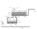
- FIG. 1 is a diagram illustrating an example of a configuration of a main part of an ink jet recording apparatus, which includes an ink tank 1, an ink supply path 2, and an ink jet recording head 4.
- the ink tank 1 includes a tank internal heater 17 that heats inkjet ink, an air communication valve 12 that communicates the inside and the outside of the ink tank 1, a back pressure adjustment mechanism 11, a stirring device 15, an ink supply port 18, And a tank internal thermistor 16.
- the inkjet ink is filled into the ink tank 1 from the ink supply port 18.
- the liquid level 14 of the ink jet ink filled in the ink tank 1 is in contact with the air 13 to form a gas-liquid interface.
- the ink tank 1 there is a tank internal heater 17 for heating the ink jet ink.
- a tank internal thermistor 16 that detects whether the heating temperature of the inkjet ink is appropriate. When the heating temperature is low, the temperature is controlled by increasing the output of the tank internal heater 17.
- the atmosphere communication valve 12 that communicates the inside of the ink tank 1 and the atmosphere can discharge the gas generated from the heated inkjet ink to the atmosphere.
- a back pressure adjusting mechanism 11 that adjusts the back pressure inside the ink tank 1 is provided.
- the back pressure is a force that draws the inkjet ink in the nozzle 44 into the inkjet recording head 4.
- the back pressure is adjusted so that the ink jet ink does not leak from the nozzle 44 and an appropriate meniscus can be formed.
- the stirring device 15 for stirring the ink jet ink inside the ink tank 1.
- the stirring device 15 may be, for example, a stirring tool.
- the ink supply path 2 has a supply valve 21 and a pump 22.
- a supply valve 21 provided between the ink tank 1 and the ink supply path 2
- the inkjet ink inside the ink tank 1 is supplied to the inkjet recording head 4 via the ink supply path 2.
- the pump 22 provided in the ink supply path 2
- the inkjet ink inside the ink tank 1 can be efficiently supplied to the inkjet recording head 4.
- the inkjet ink heated in the ink tank 1 is preferably cooled by the tube wall of the ink supply path 2 while passing through the ink supply path 2; more preferably, the temperature of the inkjet ink is decreased by 5 to 30 ° C. .
- the ink jet recording head 4 includes a common channel 41, a plurality of nozzles 44 arranged along the ink channel direction, a head internal thermistor 42, and a head internal heater 43.
- the ink jet ink passes through the ink supply path 2 and is supplied to the ink common flow path 41 of the ink jet recording head 4.
- the inkjet ink supplied to the common flow path 41 is sent to a plurality of pressure chambers (not shown).
- Each pressure chamber is separated by a partition (not shown), and a piezoelectric element, which is a piezoelectric material having electrodes, is disposed on the partition.
- a nozzle 44 is arranged in each pressure chamber. Ink jet ink droplets are ejected from the nozzles 44 of the pressure chambers by the movement of the piezoelectric elements.
- the temperature of the ink jet ink inside the ink jet recording head 4 is detected by the head internal thermistor 42. If the ink temperature is low, the temperature is controlled by increasing the output of the head internal heater 43.
- the conveyance platform 5 for moving the recording medium relative to the recording medium is mounted with the recording medium, and adjusts the temperature of the recording medium to a predetermined temperature.
- the temperature control means for the recording medium include a method for adjusting the temperature of the recording medium from the back surface by attaching a cooling device and a heating device to the transport base 5 for fixing the recording medium or a fixing drum in advance, and cooling air and temperature.
- a method of adjusting the temperature of the recording medium in advance before inkjet recording is included.
- a method of adjusting the temperature of the recording medium from the back surface is preferable in order to make the temperature of the recording medium uniform.
- the light source 6 covers the entire width of the recording medium and is arranged on the downstream side of the ink jet recording head 4 in the recording medium conveyance direction.
- the light source 6 irradiates the droplets ejected by the inkjet recording head 4 and landed on the recording medium with light to cure the droplets.
- the light source is preferably an LED.
- the LED as the light source is preferably installed with ultraviolet rays of 370 to 410 nm so that the peak illuminance on the image surface is 0.5 to 10 W / cm 2 in order to cure the ink droplets. It is more preferable to install so as to be 2 .
- the amount of light applied to the image is preferably less than 350 mJ / cm 2 . This is to prevent the radiant heat from being applied to the ink droplets.
- FIG. 2 is a diagram showing an example of a configuration of a main part of the ink jet recording apparatus, and can be configured in the same manner as the ink jet recording apparatus of FIG. 1 except that an ink supply path for communicating the ink jet recording head and the ink tank is provided.
- the ink discharge path 3 has an ink discharge valve 31. By opening the discharge valve 31 provided at the boundary between the ink tank 1 and the ink discharge path 3, the ink jet ink inside the ink jet recording head 4 is discharged to the ink tank 1 through the ink discharge path 3.
- the present embodiment is an inkjet recording method using an actinic ray curable inkjet ink having an ink viscosity at 25 ° C. of 1.0 ⁇ 10 3 to 1.0 ⁇ 10 6 mPa ⁇ s, and includes at least the following: Steps (1) to (4) are included, and steps (5) and (6) may be further included.
- Steps (1) to (4) are included, and steps (5) and (6) may be further included.
- Step of supplying heated actinic ray curable inkjet ink to inkjet recording head (3) Supplying to inkjet recording head The step of discharging the actinic radiation curable inkjet ink to a temperature of 70 ° C. to less than 120 ° C.
- Actinic rays are applied to the actinic radiation curable inkjet ink ejected onto the recording medium (5)
- the actinic ray curable inkjet ink may be any inkjet ink as described above. In other words, any actinic ray curable inkjet ink having a specific viscosity may be used.
- the ink-jet ink is filled into the ink tank from the ink supply port.
- the filled ink-jet ink is communicated with the atmosphere by opening the atmosphere communication valve, and the ink-jet ink is filled with a gas-liquid interface.
- the ink-jet ink filled in the ink tank does not need to be ink contained in a special package, and the ink-jet recording method of this embodiment can be realized with a simple apparatus.
- the ink-jet ink is heated to A ° C. by a heater in the ink tank.
- the ink temperature (A ° C.) in the ink tank is preferably 5 to 30 ° C. and more preferably 5 to 20 ° C. higher than the ink temperature (B ° C.) in the ink head described later.
- the saturated dissolved gas concentration of the ink decreases.
- the supersaturated gas becomes bubbles, and the gas dissolution concentration in the ink (the amount of dissolved gas with respect to the amount of ink) decreases.
- the temperature of the ink is too high, the ink component may be deteriorated.
- the ink can be heated at a heating rate of 0.08 to 0.12 ° C./s, for example, up to the ink temperature (A ° C.).
- the back pressure of the ink-jet ink in the ink tank is preferably adjusted. By adjusting the back pressure, a meniscus can be formed in the ink droplet at the nozzle tip, and the ejection of the ink droplet can be stabilized.
- the back pressure is preferably about ⁇ 22 to ⁇ 18 cmAq.
- the influence of the back pressure on the temperature change of the ink or the gas solubility is very small.
- the inkjet ink heated within the temperature range is supplied to an inkjet recording head via an ink supply path.
- the ink supply path is a closed system, and the inkjet ink in the ink supply path cannot come into contact with outside air. That is, the gas dissolution concentration in the ink jet ink in the ink supply path is the same as the gas dissolution concentration of the ink jet ink in the ink tank.
- Ink supply to the ink jet recording head can also be performed by operating a pump on the ink supply path.
- the inkjet ink is cooled by the tube wall of the ink supply path while passing through the ink supply path.
- the ink supply path may be covered with a coolant such as water to cool the inkjet ink.
- the inkjet ink is cooled to increase the saturated dissolved gas concentration.
- the “gas dissolved concentration / saturated dissolved concentration” of the ink jet ink in the ink jet recording head rather than the “gas dissolved concentration / saturated dissolved gas concentration” of the ink jet ink in the ink tank.
- “Gas concentration” is lower.
- the inkjet ink cooled in the ink supply path is supplied to a common channel in the inkjet recording head.
- the temperature is detected by the head internal thermistor, and the output of the head internal heater can be increased and heated to the temperature described later.
- the ink temperature (B ° C.) in the inkjet recording head is preferably in the range of 70 ° C. or higher and lower than 120 ° C., more preferably in the range of 70 to 100 ° C. If the ink temperature is too high, the ink jet recording head member may be deteriorated and the ink component may be deteriorated. If the ink temperature is too low, the ink viscosity cannot be lowered sufficiently, and the ejection properties of the ink droplets are lowered.
- the ink temperature in the ink jet recording head is preferably lower than the boiling point of each component of the ink jet ink.
- the ink temperature (A ° C.) and ink temperature (B ° C.) described above are temperatures under atmospheric pressure (101325 Pa) unless otherwise specified.
- Inkjet ink is ejected from each nozzle of the inkjet recording head. If the ejection is continuously performed at a high ejection driving frequency at this time, bubbles may be generated in the ink in the ink jet recording head due to pressure fluctuation in the ink jet recording head. When bubbles are generated in the ink jet recording head, the pressure for injection is absorbed by the bubbles, which causes problems such as the inability to eject droplets from the nozzles and bending of the injection angle. In order to prevent the occurrence of this phenomenon, measures are taken such as using deaerated ink in advance, or providing a deaeration film on the printer to perform deaeration before use. However, the ink-jet ink used in the present embodiment has a problem that it cannot be degassed by a conventional method because it has a very high viscosity around room temperature and is in a gel form.
- air may enter the pressure chamber through the nozzle, resulting in injection bending or missing injection.
- a head maintenance method for recovering ejection failure an operation of discharging a certain amount of inkjet ink from the nozzle and wiping the inkjet ink adhering to the nozzle plate with a nonwoven fabric or a rubber plate is performed. It is desirable to recover ejection failure by a single maintenance operation or by discharging a small amount of ink.
- the “gas dissolved concentration / saturated dissolved gas concentration” of the inkjet ink in the inkjet recording head is reduced. Therefore, stable ejection can be realized even when continuous ejection is performed at a high ejection frequency or when ink jet ink in the ink jet recording head absorbs air that has entered through the nozzles. Further, nozzle recovery can be reliably performed with a small ink discharge amount for the maintenance operation. This is because the ink temperature in the ink jet recording head is set 5-30 ° C. lower than the ink temperature in the ink tank.
- the amount of droplets ejected from each nozzle of the inkjet recording head is preferably 1 to 10 pl depending on the resolution of the image.
- the recording medium is not particularly limited, and is a plain paper used for copying, a paper base such as art paper, a normal uncoated paper, a coated paper in which both sides of the base paper are coated with a resin, etc.
- a paper base such as art paper
- a normal uncoated paper such as art paper
- a coated paper in which both sides of the base paper are coated with a resin, etc.
- various non-absorbable plastics and films thereof used for so-called soft packaging can be used.
- plastic films include PET film, OPS film, OPP film, ONY film, PVC film, PE film, and TAC film.
- it is applicable also to metals and glass.
- the surface temperature of the recording medium is 5-15 ° C. lower than the gelling temperature of the gelling agent, and may be 5-10 ° C. lower. More preferred.
- the ink jet recording method of the present embodiment is effective in both the so-called shuttle recording method and the single pass recording method, but in the single pass recording method which is high speed recording, the conventional image forming method using actinic ray curable ink is used. A more remarkable effect can be obtained.
- the conveyance speed of the recording medium in the single pass recording method is preferably 500 to 3000 mm / s.
- the conveyance speed is too high, the image quality is deteriorated or the ink is not sufficiently cured.
- the light applied to the ink droplets attached to the recording medium is preferably ultraviolet light from an LED light source.
- an LED light source Specifically, a 395 nm, water-cooled LED manufactured by Phoseon Technology can be used.
- An ultraviolet light source may be a metal halide lamp or the like, but by using an LED as a light source, an effect of preventing poor curing of the cured film surface of the ink droplet due to melting of the ink droplet by the radiant heat of the light source can be obtained. .
- the light irradiation to the ink droplets is performed within 10 seconds after the ink droplets adhere to the recording medium, preferably 0.001 seconds to 5 seconds, in order to prevent the adjacent ink droplets from coalescing. Within a range of 0.01 second to 2 seconds.
- the light irradiation is preferably performed after ejecting ink droplets from all the ink jet recording heads accommodated in the head carriage.
- a circulation flow path can be formed between the ink jet recording head and the ink tank.
- the saturated dissolved gas concentration can be lowered again in the ink tank and the gas dissolved concentration can be lowered, so that the injection stability can be ensured.
- the ink can be circulated at the initial introduction of the ink or the maintenance of the apparatus.
- the ink jet ink in the ink tank can be fluidized by stirring.
- the fluidizing method include a method of causing the ink jet ink to flow by rotating a stirring device. By causing the ink-jet ink in the ink tank to flow, the ink temperature becomes uniform.
- Pigment dispersion 1 was prepared by the following procedure. The following two compounds were placed in a stainless beaker and dissolved by stirring with heating for 1 hour while heating on a hot plate at 65 ° C.
- Pigment dispersant Azisper PB824 (Ajinomoto Fine Techno Co., Ltd.) 9 parts by mass
- Polymerizable compound APG-200 (Tripropylene glycol diacrylate, Shin Nakamura Chemical Co., Ltd.) 70 parts by mass
- Pigment Red 122 manufactured by Dainichi Seika, Chromofine Red 6112JC
- Pigment Red 122 manufactured by Dainichi Seika, Chromofine Red 6112JC
- it put into a glass bottle together with 200 g of zirconia beads having a diameter of 0.5 mm and sealed, and dispersed for 8 hours with a paint shaker. Thereafter, the zirconia beads were removed to prepare a pigment dispersion 1.
- NK ester A-400 polyethylene glycol diacrylate, manufactured by Shin-Nakamura Chemical Co., Ltd. 29.8 parts by mass SR494 (4EO-modified pentaerythritol tetraacrylate, manufactured by SARTOMER) 15.0 parts by mass SR499 (6EO-modified trimethylolpropane triacrylate, 20.0 parts by mass)
- TPO phosphine oxide, DAROCURE TPO, manufactured by Ciba Japan
- ITX Isopropylthioxanthone, Speedcure ITX, manufactured by Lambson
- EDB Ammonium auxiliary, Speedcure EDB, manufactured by Lambson
- Pigment dispersion 1 19.0 parts by mass
- Pigment dispersion 2 was prepared by the following procedure. The following two compounds were placed in a stainless beaker and dissolved by stirring with heating for 1 hour while heating on a hot plate at 65 ° C.
- Pigment dispersant Ajisper PB824 (Ajinomoto Fine Techno Co., Ltd.) 9 parts by weight
- Polymerizable compound OXT221 (Oxetane compound, manufactured by Toagosei Co., Ltd.) 70 parts by weight
- Pigment dispersion 2 19.0 parts by mass
- Ink prepared in a temperature-controllable stress-controlled rheometer (Physica MCR300, manufactured by Anton Paar) was set and heated to 100 ° C., cooled to 25 ° C. at a temperature decrease rate of 0.1 ° C./s, and a share rate of 11. Viscosity measurements were taken at 7 s ⁇ 1 . The measurement was performed using a cone plate (CP75-1, manufactured by Anton Paar) having a diameter of 75 mm and a cone angle of 1 °. The temperature was controlled by a Peltier element type temperature controller (TEK150P / MC1) attached to the Physica MCR300.
- TEK150P / MC1 Peltier element type temperature controller
- the temperature at which the viscosity rapidly increased was read from the viscosity curve obtained by the measurement, and the temperature at which the viscosity showed 500 mPa ⁇ s was defined as the gelation temperature.
- the temperature of the ink was adjusted to 25 ° C. Thereafter, the mixture was heated to 100 ° C. at a heating temperature of 0.1 ° C./s, and the viscosity was measured at a shear rate of 11.7 s ⁇ 1 .
- the temperature at which the viscosity sharply decreased was read from the viscosity curve obtained by the measurement, and the temperature at which the viscosity showed 500 mPa ⁇ s was defined as the solation temperature.
- Table 1 shows the gelation temperature and the solation temperature of ink 1 and ink 2.
- Example 1 With the configuration shown in FIG. 1, an ink tank and an inkjet recording head were connected, and bubble discharge evaluation and continuous ejection evaluation were performed.
- the ink temperature in the ink tank was adjusted to the temperature shown in Table 2.
- the ink temperature in the ink tank was heated by a heater provided in the ink tank.
- the ink temperature in the ink tank was detected by a thermistor and controlled by adjusting the heater output.
- the ink tank internal volume of 200 cm 3 the experiment was started in a state in which the ink-jet ink was 150 cm 3 filled.
- a stirring device was provided in the ink tank. In the case of stirring, continuous ejection evaluation was performed while weakly stirring the inkjet ink in the ink tank.
- the ink jet recording head As the ink jet recording head, a piezo head having a nozzle diameter of 24 ⁇ m and a nozzle number of 512 nozzles was used. Heating was performed so that the ink temperature in the ink jet recording head became the temperature shown in Table 2. The ink temperature in the ink jet recording head was heated by a heater provided in the ink jet recording head. The ink temperature in the ink jet recording head was detected by a thermistor and controlled by adjusting the output of the heater. The volume in the ink jet recording head is about 1 cm 3 , and the volume of the ink supply path connecting the ink jet recording head and the ink tank is about 3 cm 3 .
- the air communication valve of the ink tank was opened until the ink jet ink in the ink tank and the ink jet ink in the ink jet recording head each reached the set temperature.
- the air communication valve was closed after each ink temperature reached the set temperature.
- the back pressure was kept at ⁇ 20 cmAq for 5 minutes by the back pressure adjusting mechanism.
- Example 2 With the configuration shown in FIG. 2, the ink tank and the inkjet recording head were connected, and bubble discharge evaluation and continuous ejection evaluation were performed.
- the ink temperature in the ink tank was adjusted to the temperature shown in Table 3.
- the ink temperature in the ink tank was heated by a heater provided in the ink tank.
- the ink temperature in the ink tank was detected by a thermistor and controlled by adjusting the heater output.
- the ink tank internal volume of 200 cm 3 the experiment was started in a state in which the ink-jet ink was 150 cm 3 filled.
- a stirring device was provided in the ink tank. In the case of stirring, continuous ejection evaluation was performed while weakly stirring the ink in the ink tank.
- the ink jet recording head As the ink jet recording head, a piezo head having a nozzle diameter of 24 ⁇ m and a nozzle number of 512 nozzles was used. Heating was performed so that the ink temperature in the ink jet recording head became the temperature shown in Table 3. The ink temperature in the ink jet recording head was heated by a heater provided in the ink jet recording head. The ink temperature in the ink jet recording head was detected by a thermistor and controlled by adjusting the output of the heater. The volume in the ink jet recording head is about 1 cm 3 , and the volume of the ink supply path connecting the ink jet recording head and the ink tank is about 6 cm 3 .
- the air communication valve of the ink tank was opened until the ink in the ink tank and the ink in the ink jet recording head reached the set temperature.
- the air communication valve was closed after each ink temperature reached the set temperature.
- the back pressure was kept at ⁇ 20 cmAq for 5 minutes by the back pressure adjusting mechanism.
- Example 3 With the configuration shown in FIG. 2, the ink tank and the inkjet recording head were connected, and bubble discharge evaluation and continuous ejection evaluation were performed.
- the experiment was performed under the same conditions as in Experimental Example 2, except that the injection was performed using a piezo head having a nozzle diameter of 28 ⁇ m and a number of nozzles of 256 nozzles with an appropriate liquid amount of 12 pl, a droplet speed of 5 m / sec, and an injection frequency of 18 kHz.
- the ink temperature (T2) of the inkjet recording head is set to 70 ° C. or higher and lower than 120 ° C., and the difference (T1 ⁇ T2) from the ink temperature (T1) in the ink tank is set within a range of 5 ° C. to 30 ° C.
- the inkjet recording method of the present invention when recording an actinic ray curable inkjet ink, particularly an actinic ray curable inkjet ink containing a gelling agent, gas mixed into the inkjet ink at the initial ink introduction or head cleaning The influence of the gas entering the ink chamber of the ink jet recording head on the ejection is reduced. Furthermore, a highly reliable ink jet recording method can be provided by preventing missing shots and flying bends during continuous ejection.
Abstract
Priority Applications (4)
| Application Number | Priority Date | Filing Date | Title |
|---|---|---|---|
| US14/381,486 US9527310B2 (en) | 2012-03-01 | 2013-03-01 | Inkjet printing method |
| EP13754669.3A EP2821229B1 (fr) | 2012-03-01 | 2013-03-01 | Procédé d'impression à jet d'encre |
| CN201380011973.9A CN104144788B (zh) | 2012-03-01 | 2013-03-01 | 喷墨记录方法 |
| JP2014502055A JP5867585B2 (ja) | 2012-03-01 | 2013-03-01 | インクジェット記録方法 |
Applications Claiming Priority (2)
| Application Number | Priority Date | Filing Date | Title |
|---|---|---|---|
| JP2012-045488 | 2012-03-01 | ||
| JP2012045488 | 2012-03-01 |
Publications (1)
| Publication Number | Publication Date |
|---|---|
| WO2013128945A1 true WO2013128945A1 (fr) | 2013-09-06 |
Family
ID=49082156
Family Applications (1)
| Application Number | Title | Priority Date | Filing Date |
|---|---|---|---|
| PCT/JP2013/001281 WO2013128945A1 (fr) | 2012-03-01 | 2013-03-01 | Procédé d'impression à jet d'encre |
Country Status (5)
| Country | Link |
|---|---|
| US (1) | US9527310B2 (fr) |
| EP (1) | EP2821229B1 (fr) |
| JP (1) | JP5867585B2 (fr) |
| CN (1) | CN104144788B (fr) |
| WO (1) | WO2013128945A1 (fr) |
Cited By (8)
| Publication number | Priority date | Publication date | Assignee | Title |
|---|---|---|---|---|
| JP2015089540A (ja) * | 2013-11-06 | 2015-05-11 | 積水化学工業株式会社 | 硬化物膜の製造方法、電子部品の製造方法及び電子部品 |
| WO2015068722A1 (fr) * | 2013-11-06 | 2015-05-14 | 積水化学工業株式会社 | Procédé de fabrication d'un film durci, procédé de fabrication d'un composant électronique et composant électronique |
| WO2015137498A1 (fr) * | 2014-03-14 | 2015-09-17 | コニカミノルタ株式会社 | Méthode d'enregistrement à jet d'encre |
| WO2015152177A1 (fr) * | 2014-04-03 | 2015-10-08 | コニカミノルタ株式会社 | Procédé de formation d'image |
| CN104981299A (zh) * | 2013-11-06 | 2015-10-14 | 积水化学工业株式会社 | 固化物膜的制造方法、电子部件的制造方法及电子部件 |
| JP2016036997A (ja) * | 2014-08-08 | 2016-03-22 | コニカミノルタ株式会社 | 活性光線硬化型インクジェットインクの脱気方法、インクジェット記録方法および活性光線硬化型インクジェットインク |
| US9649849B2 (en) | 2015-06-17 | 2017-05-16 | Toshiba Tec Kabushiki Kaisha | Ink circulation device and ink jet recording apparatus |
| JP2020023126A (ja) * | 2018-08-08 | 2020-02-13 | コニカミノルタ株式会社 | インクジェット記録装置、及び、インクジェット記録装置の制御方法 |
Families Citing this family (10)
| Publication number | Priority date | Publication date | Assignee | Title |
|---|---|---|---|---|
| JP6183356B2 (ja) * | 2012-04-27 | 2017-08-23 | コニカミノルタ株式会社 | 画像形成方法 |
| US9695325B2 (en) * | 2014-09-16 | 2017-07-04 | Ricoh Company, Ltd. | Active energy ray curable composition, active energy ray curable ink, composition stored container, two dimensional or three dimensional image forming apparatus, image forming method, cured material, and processed product |
| EP3330329B1 (fr) | 2016-12-02 | 2022-06-08 | Ricoh Company, Ltd. | Appareil d'enregistrement à jet d'encre, imprimante et procédé de fabrication d'un produit durci |
| JP2019119844A (ja) * | 2018-01-10 | 2019-07-22 | 株式会社リコー | 硬化型液体組成物、組成物収容容器、液体組成物吐出装置、硬化物、及び硬化物の製造方法 |
| US11299641B2 (en) | 2018-01-10 | 2022-04-12 | Ricoh Company, Ltd. | Curable liquid composition, composition-accommodating container, liquid composition discharging device, cured material, and method of manufacturing cured material |
| JP7221113B2 (ja) * | 2019-03-29 | 2023-02-13 | 住友重機械ファインテック株式会社 | 工作機械用の液体循環装置及びタンク |
| GB2584617B (en) * | 2019-05-21 | 2021-10-27 | Xaar Technology Ltd | Piezoelectric droplet deposition apparatus optimised for high viscosity fluids, and methods and control system therefor |
| KR102290370B1 (ko) * | 2019-11-13 | 2021-08-19 | 이재율 | 실리콘잉크젯 프린터 |
| JP2022113539A (ja) * | 2021-01-25 | 2022-08-04 | 東芝テック株式会社 | 液体吐出ヘッド及び液体吐出装置 |
| CN113856964B (zh) * | 2021-08-05 | 2023-05-09 | 济南晶博电子有限公司 | 一种电子元器件制造用的注胶装置的工作方法 |
Citations (53)
| Publication number | Priority date | Publication date | Assignee | Title |
|---|---|---|---|---|
| US2848328A (en) | 1954-06-16 | 1958-08-19 | Eastman Kodak Co | Light sensitive diazo compound and binder composition |
| US2852379A (en) | 1955-05-04 | 1958-09-16 | Eastman Kodak Co | Azide resin photolithographic composition |
| US2940853A (en) | 1958-08-21 | 1960-06-14 | Eastman Kodak Co | Azide sensitized resin photographic resist |
| JPS446413B1 (fr) | 1965-06-28 | 1969-03-19 | ||
| JPS459610B1 (fr) | 1965-07-19 | 1970-04-07 | ||
| US3567453A (en) | 1967-12-26 | 1971-03-02 | Eastman Kodak Co | Light sensitive compositions for photoresists and lithography |
| JPS471604B1 (fr) | 1968-12-06 | 1972-01-17 | ||
| JPS5539162B2 (fr) | 1975-05-02 | 1980-10-08 | ||
| JPS591504A (ja) | 1982-06-26 | 1984-01-06 | Nippon Oil & Fats Co Ltd | 光重合開始剤組成物 |
| JPS591281B2 (ja) | 1971-09-03 | 1984-01-11 | ミネソタ マイニング アンド マニュファクチュアリング コンパニ− | ヒカリジユウゴウカイシザイ |
| JPS5914023B2 (ja) | 1977-12-07 | 1984-04-02 | 工業技術院長 | フルオロアルキルピリジン類の製造方法 |
| EP0109851A2 (fr) | 1982-11-22 | 1984-05-30 | Minnesota Mining And Manufacturing Company | Compositions polymérisables par apport d'énergie contenant des initiateurs organométalliques |
| JPS59107344A (ja) | 1982-12-13 | 1984-06-21 | Hitachi Chem Co Ltd | 感光性樹脂組成物 |
| JPS59142205A (ja) | 1983-02-02 | 1984-08-15 | Nippon Oil & Fats Co Ltd | 高感度光開始剤組成物 |
| EP0126712A1 (fr) | 1983-05-18 | 1984-11-28 | Ciba-Geigy Ag | Composition durcissable et son utilisation |
| JPS6060104A (ja) | 1983-09-12 | 1985-04-06 | Fuji Photo Film Co Ltd | 光重合性組成物 |
| JPS619621B2 (fr) | 1978-05-18 | 1986-03-25 | Fuji Photo Film Co Ltd | |
| JPS61151197A (ja) | 1984-12-20 | 1986-07-09 | チバ‐ガイギー アーゲー | チタノセン類およびこれらのチタノセン類を含有する照射重合開始剤 |
| JPS61243807A (ja) | 1985-04-23 | 1986-10-30 | Nippon Oil & Fats Co Ltd | 光重合開始剤 |
| JPH0154440B2 (fr) | 1982-11-01 | 1989-11-17 | Takeo Meguro | |
| JPH01297251A (ja) * | 1988-05-25 | 1989-11-30 | Canon Inc | インクジェット記録装置 |
| JPH02182701A (ja) | 1988-11-08 | 1990-07-17 | Mead Corp:The | 遷移金属配立錯体カチオンとボレートアニオンを含有した感光性組成物及びそれを使用した感光性材料 |
| JPH03209477A (ja) | 1989-10-13 | 1991-09-12 | Fuji Photo Film Co Ltd | アルミナート錯体からなる光重合開始剤及び光重合性組成物 |
| JPH069714A (ja) | 1992-06-29 | 1994-01-18 | Sumitomo Chem Co Ltd | 光重合性組成物及び光制御板の製造方法 |
| JPH0731399B2 (ja) | 1984-12-21 | 1995-04-10 | 三菱化学株式会社 | 光重合性組成物 |
| JPH07159983A (ja) | 1993-12-03 | 1995-06-23 | Fuji Photo Film Co Ltd | 感光性印刷版 |
| JPH08224982A (ja) | 1995-02-22 | 1996-09-03 | Konica Corp | 転写箔及びそれを用いたidカード |
| JPH10863A (ja) | 1996-06-12 | 1998-01-06 | Konica Corp | 熱転写シート及びそれを用いて形成した画像要素 |
| JP2711491B2 (ja) | 1992-02-07 | 1998-02-10 | 東洋インキ製造株式会社 | スルホニウム錯体またはオキソスルホニウム錯体 |
| JP2803454B2 (ja) | 1992-03-13 | 1998-09-24 | 東洋インキ製造株式会社 | スルホニウム錯体またはオキソスルホニウム錯体 |
| JPH11124403A (ja) | 1997-05-16 | 1999-05-11 | Dainippon Ink & Chem Inc | マレイミド誘導体を含有する活性エネルギー線硬化性組成物及び該活性エネルギー線硬化性組成物の硬化方法 |
| JP2001031892A (ja) | 1999-07-23 | 2001-02-06 | Toyo Ink Mfg Co Ltd | 紫外線硬化型塗料組成物及びその利用 |
| JP2001040068A (ja) | 1999-07-27 | 2001-02-13 | Asahi Denka Kogyo Kk | 光重合性組成物 |
| JP2001055507A (ja) | 1999-08-19 | 2001-02-27 | Kansai Paint Co Ltd | 活性エネルギー線硬化性組成物およびその被膜形成方法 |
| JP2001220526A (ja) | 2000-02-09 | 2001-08-14 | Brother Ind Ltd | インクジェット記録方式用エネルギー線硬化型組成物 |
| JP2001310937A (ja) | 2000-04-27 | 2001-11-06 | Hitachi Chem Co Ltd | 硬化性オキセタン組成物およびその硬化方法ならびにその方法により得られる硬化物 |
| JP2001310938A (ja) | 2000-04-28 | 2001-11-06 | Showa Denko Kk | 重合性組成物、その硬化物と製造方法 |
| JP2003105239A (ja) * | 2001-06-27 | 2003-04-09 | Konica Corp | インクジェット記録方法及びインク |
| JP3622062B2 (ja) | 1995-10-19 | 2005-02-23 | 愛知機械工業株式会社 | ギヤの製造方法 |
| JP2005053048A (ja) * | 2003-08-01 | 2005-03-03 | Canon Finetech Inc | インクジェット記録装置 |
| JP2005126507A (ja) | 2003-10-22 | 2005-05-19 | Konica Minolta Holdings Inc | インクジェット用インク及びそれを用いたインクジェット記録方法 |
| JP2005255821A (ja) | 2004-03-11 | 2005-09-22 | Konica Minolta Holdings Inc | 活性光線硬化型インクジェットインクとそれを用いたインクジェット記録方法 |
| JP3713109B2 (ja) | 1996-10-29 | 2005-11-02 | 株式会社ムラコシ精工 | ドア錠装置 |
| JP2006193745A (ja) | 2005-01-14 | 2006-07-27 | Xerox Corp | 硬化性ゲル化剤添加剤を含む放射線硬化性インク |
| JP3818015B2 (ja) | 2000-05-02 | 2006-09-06 | 富士ゼロックス株式会社 | 画像定着装置 |
| JP2007152873A (ja) | 2005-12-08 | 2007-06-21 | Konica Minolta Holdings Inc | インクジェット記録方法及びそれに用いるインクジェット記録用インク |
| JP2008044212A (ja) | 2006-08-14 | 2008-02-28 | Seiko Epson Corp | 液滴吐出ヘッド及び液滴吐出装置 |
| JP2009510184A (ja) | 2005-09-01 | 2009-03-12 | オセ−テクノロジーズ・ベー・ヴエー | 放射線硬化性インクジェットインクおよびこのインクを用いて被印刷物を印刷する方法 |
| JP4323684B2 (ja) | 1999-06-30 | 2009-09-02 | キヤノン株式会社 | 磁性体分散型樹脂キャリアの製造方法 |
| JP2010111790A (ja) | 2008-11-07 | 2010-05-20 | Konica Minolta Holdings Inc | 活性光線硬化型インクジェット用インクとそれを用いたインクジェット記録方法 |
| JP2010240948A (ja) * | 2009-04-03 | 2010-10-28 | Seiko Epson Corp | 液体噴射装置 |
| JP2011051172A (ja) * | 2009-08-31 | 2011-03-17 | Seiko Epson Corp | 液体噴射装置 |
| JP2011121297A (ja) * | 2009-12-11 | 2011-06-23 | Konica Minolta Holdings Inc | インクジェット画像形成方法 |
Family Cites Families (7)
| Publication number | Priority date | Publication date | Assignee | Title |
|---|---|---|---|---|
| US6685311B2 (en) | 2001-06-26 | 2004-02-03 | Konica Corporation | Ink-jet ink, ink-jet cartridge, ink-jet recording unit and ink-jet recording apparatus |
| JP4741761B2 (ja) * | 2001-09-14 | 2011-08-10 | キヤノン株式会社 | インクジェット記録ヘッド、該インクジェット記録ヘッドを用いたインクジェット記録装置、およびインクジェット記録ヘッドの製造方法 |
| JP5600910B2 (ja) * | 2009-08-31 | 2014-10-08 | セイコーエプソン株式会社 | 液体噴射装置及び液体噴射装置における液体噴射ヘッドのクリーニング方法 |
| JP5515523B2 (ja) * | 2009-08-31 | 2014-06-11 | セイコーエプソン株式会社 | 液体噴射装置 |
| JP5552778B2 (ja) * | 2009-09-02 | 2014-07-16 | セイコーエプソン株式会社 | 液体供給方法 |
| EP2607433B1 (fr) * | 2010-08-19 | 2020-11-11 | Konica Minolta Holdings, Inc. | Encre durcissable par rayonnement actif et procédé d'enregistrement à jet d'encre durcissable par rayonnement actif |
| US10029483B2 (en) * | 2012-04-25 | 2018-07-24 | Seiko Epson Corporation | Ink jet recording method, ultraviolet-ray curable ink, and ink jet recording apparatus |
-
2013
- 2013-03-01 WO PCT/JP2013/001281 patent/WO2013128945A1/fr active Application Filing
- 2013-03-01 JP JP2014502055A patent/JP5867585B2/ja active Active
- 2013-03-01 CN CN201380011973.9A patent/CN104144788B/zh active Active
- 2013-03-01 US US14/381,486 patent/US9527310B2/en active Active
- 2013-03-01 EP EP13754669.3A patent/EP2821229B1/fr active Active
Patent Citations (53)
| Publication number | Priority date | Publication date | Assignee | Title |
|---|---|---|---|---|
| US2848328A (en) | 1954-06-16 | 1958-08-19 | Eastman Kodak Co | Light sensitive diazo compound and binder composition |
| US2852379A (en) | 1955-05-04 | 1958-09-16 | Eastman Kodak Co | Azide resin photolithographic composition |
| US2940853A (en) | 1958-08-21 | 1960-06-14 | Eastman Kodak Co | Azide sensitized resin photographic resist |
| JPS446413B1 (fr) | 1965-06-28 | 1969-03-19 | ||
| JPS459610B1 (fr) | 1965-07-19 | 1970-04-07 | ||
| US3567453A (en) | 1967-12-26 | 1971-03-02 | Eastman Kodak Co | Light sensitive compositions for photoresists and lithography |
| JPS471604B1 (fr) | 1968-12-06 | 1972-01-17 | ||
| JPS591281B2 (ja) | 1971-09-03 | 1984-01-11 | ミネソタ マイニング アンド マニュファクチュアリング コンパニ− | ヒカリジユウゴウカイシザイ |
| JPS5539162B2 (fr) | 1975-05-02 | 1980-10-08 | ||
| JPS5914023B2 (ja) | 1977-12-07 | 1984-04-02 | 工業技術院長 | フルオロアルキルピリジン類の製造方法 |
| JPS619621B2 (fr) | 1978-05-18 | 1986-03-25 | Fuji Photo Film Co Ltd | |
| JPS591504A (ja) | 1982-06-26 | 1984-01-06 | Nippon Oil & Fats Co Ltd | 光重合開始剤組成物 |
| JPH0154440B2 (fr) | 1982-11-01 | 1989-11-17 | Takeo Meguro | |
| EP0109851A2 (fr) | 1982-11-22 | 1984-05-30 | Minnesota Mining And Manufacturing Company | Compositions polymérisables par apport d'énergie contenant des initiateurs organométalliques |
| JPS59107344A (ja) | 1982-12-13 | 1984-06-21 | Hitachi Chem Co Ltd | 感光性樹脂組成物 |
| JPS59142205A (ja) | 1983-02-02 | 1984-08-15 | Nippon Oil & Fats Co Ltd | 高感度光開始剤組成物 |
| EP0126712A1 (fr) | 1983-05-18 | 1984-11-28 | Ciba-Geigy Ag | Composition durcissable et son utilisation |
| JPS6060104A (ja) | 1983-09-12 | 1985-04-06 | Fuji Photo Film Co Ltd | 光重合性組成物 |
| JPS61151197A (ja) | 1984-12-20 | 1986-07-09 | チバ‐ガイギー アーゲー | チタノセン類およびこれらのチタノセン類を含有する照射重合開始剤 |
| JPH0731399B2 (ja) | 1984-12-21 | 1995-04-10 | 三菱化学株式会社 | 光重合性組成物 |
| JPS61243807A (ja) | 1985-04-23 | 1986-10-30 | Nippon Oil & Fats Co Ltd | 光重合開始剤 |
| JPH01297251A (ja) * | 1988-05-25 | 1989-11-30 | Canon Inc | インクジェット記録装置 |
| JPH02182701A (ja) | 1988-11-08 | 1990-07-17 | Mead Corp:The | 遷移金属配立錯体カチオンとボレートアニオンを含有した感光性組成物及びそれを使用した感光性材料 |
| JPH03209477A (ja) | 1989-10-13 | 1991-09-12 | Fuji Photo Film Co Ltd | アルミナート錯体からなる光重合開始剤及び光重合性組成物 |
| JP2711491B2 (ja) | 1992-02-07 | 1998-02-10 | 東洋インキ製造株式会社 | スルホニウム錯体またはオキソスルホニウム錯体 |
| JP2803454B2 (ja) | 1992-03-13 | 1998-09-24 | 東洋インキ製造株式会社 | スルホニウム錯体またはオキソスルホニウム錯体 |
| JPH069714A (ja) | 1992-06-29 | 1994-01-18 | Sumitomo Chem Co Ltd | 光重合性組成物及び光制御板の製造方法 |
| JPH07159983A (ja) | 1993-12-03 | 1995-06-23 | Fuji Photo Film Co Ltd | 感光性印刷版 |
| JPH08224982A (ja) | 1995-02-22 | 1996-09-03 | Konica Corp | 転写箔及びそれを用いたidカード |
| JP3622062B2 (ja) | 1995-10-19 | 2005-02-23 | 愛知機械工業株式会社 | ギヤの製造方法 |
| JPH10863A (ja) | 1996-06-12 | 1998-01-06 | Konica Corp | 熱転写シート及びそれを用いて形成した画像要素 |
| JP3713109B2 (ja) | 1996-10-29 | 2005-11-02 | 株式会社ムラコシ精工 | ドア錠装置 |
| JPH11124403A (ja) | 1997-05-16 | 1999-05-11 | Dainippon Ink & Chem Inc | マレイミド誘導体を含有する活性エネルギー線硬化性組成物及び該活性エネルギー線硬化性組成物の硬化方法 |
| JP4323684B2 (ja) | 1999-06-30 | 2009-09-02 | キヤノン株式会社 | 磁性体分散型樹脂キャリアの製造方法 |
| JP2001031892A (ja) | 1999-07-23 | 2001-02-06 | Toyo Ink Mfg Co Ltd | 紫外線硬化型塗料組成物及びその利用 |
| JP2001040068A (ja) | 1999-07-27 | 2001-02-13 | Asahi Denka Kogyo Kk | 光重合性組成物 |
| JP2001055507A (ja) | 1999-08-19 | 2001-02-27 | Kansai Paint Co Ltd | 活性エネルギー線硬化性組成物およびその被膜形成方法 |
| JP2001220526A (ja) | 2000-02-09 | 2001-08-14 | Brother Ind Ltd | インクジェット記録方式用エネルギー線硬化型組成物 |
| JP2001310937A (ja) | 2000-04-27 | 2001-11-06 | Hitachi Chem Co Ltd | 硬化性オキセタン組成物およびその硬化方法ならびにその方法により得られる硬化物 |
| JP2001310938A (ja) | 2000-04-28 | 2001-11-06 | Showa Denko Kk | 重合性組成物、その硬化物と製造方法 |
| JP3818015B2 (ja) | 2000-05-02 | 2006-09-06 | 富士ゼロックス株式会社 | 画像定着装置 |
| JP2003105239A (ja) * | 2001-06-27 | 2003-04-09 | Konica Corp | インクジェット記録方法及びインク |
| JP2005053048A (ja) * | 2003-08-01 | 2005-03-03 | Canon Finetech Inc | インクジェット記録装置 |
| JP2005126507A (ja) | 2003-10-22 | 2005-05-19 | Konica Minolta Holdings Inc | インクジェット用インク及びそれを用いたインクジェット記録方法 |
| JP2005255821A (ja) | 2004-03-11 | 2005-09-22 | Konica Minolta Holdings Inc | 活性光線硬化型インクジェットインクとそれを用いたインクジェット記録方法 |
| JP2006193745A (ja) | 2005-01-14 | 2006-07-27 | Xerox Corp | 硬化性ゲル化剤添加剤を含む放射線硬化性インク |
| JP2009510184A (ja) | 2005-09-01 | 2009-03-12 | オセ−テクノロジーズ・ベー・ヴエー | 放射線硬化性インクジェットインクおよびこのインクを用いて被印刷物を印刷する方法 |
| JP2007152873A (ja) | 2005-12-08 | 2007-06-21 | Konica Minolta Holdings Inc | インクジェット記録方法及びそれに用いるインクジェット記録用インク |
| JP2008044212A (ja) | 2006-08-14 | 2008-02-28 | Seiko Epson Corp | 液滴吐出ヘッド及び液滴吐出装置 |
| JP2010111790A (ja) | 2008-11-07 | 2010-05-20 | Konica Minolta Holdings Inc | 活性光線硬化型インクジェット用インクとそれを用いたインクジェット記録方法 |
| JP2010240948A (ja) * | 2009-04-03 | 2010-10-28 | Seiko Epson Corp | 液体噴射装置 |
| JP2011051172A (ja) * | 2009-08-31 | 2011-03-17 | Seiko Epson Corp | 液体噴射装置 |
| JP2011121297A (ja) * | 2009-12-11 | 2011-06-23 | Konica Minolta Holdings Inc | インクジェット画像形成方法 |
Non-Patent Citations (11)
| Title |
|---|
| "Imejingu-yo Yuki Zairyo (Organic Materials for Imaging", 1993, BUNSHIN PUBLISHING CO., pages: 187 - 192 |
| "Kakyozai Handobukku (Handbook of Crosslinking Agents", 1981, TAISEISHA CO., LTD |
| "UV EB Koka Gijutsu no Oyo to Shijo (Applications and Markets of UV-EB Curing Technologies", 1989, CMC PUBLISHING CO., LTD., pages: 79 |
| "UV-EB Koka Handobukku (UV EB Curing Handbook", 1985, KOBUNSHI KANKOKAI |
| COORDINATION CHEMISTRY REVIEW, vol. 84, 1988, pages 85 - 277 |
| J. POLYM. SCI., vol. 21, 1956, pages 57 |
| JOURNAL OF IMAGING SCIENCE, vol. 30, 1986, pages 174 |
| JOURNAL OF THE SOCIETY OF RHEOLOGY, JAPAN, vol. 17, 1989, pages 86 |
| MACROMOLECULES, vol. 10, 1977, pages 1307 |
| See also references of EP2821229A4 |
| TAKIYAMA; EIICHIRO: "Poliesterujyusi Handobukku (Polyester Resin Handbook", 1988, NIKKAN KOGYO SHIMBUN, LTD |
Cited By (13)
| Publication number | Priority date | Publication date | Assignee | Title |
|---|---|---|---|---|
| WO2015068722A1 (fr) * | 2013-11-06 | 2015-05-14 | 積水化学工業株式会社 | Procédé de fabrication d'un film durci, procédé de fabrication d'un composant électronique et composant électronique |
| JP2015089540A (ja) * | 2013-11-06 | 2015-05-11 | 積水化学工業株式会社 | 硬化物膜の製造方法、電子部品の製造方法及び電子部品 |
| CN104981299A (zh) * | 2013-11-06 | 2015-10-14 | 积水化学工业株式会社 | 固化物膜的制造方法、电子部件的制造方法及电子部件 |
| US11220604B2 (en) | 2013-11-06 | 2022-01-11 | Sekisui Chemical Co., Ltd. | Method for manufacturing cured film, method for manufacturing electronic component, and electronic component |
| JPWO2015137498A1 (ja) * | 2014-03-14 | 2017-04-06 | コニカミノルタ株式会社 | インクジェット記録方法 |
| WO2015137498A1 (fr) * | 2014-03-14 | 2015-09-17 | コニカミノルタ株式会社 | Méthode d'enregistrement à jet d'encre |
| WO2015152177A1 (fr) * | 2014-04-03 | 2015-10-08 | コニカミノルタ株式会社 | Procédé de formation d'image |
| JPWO2015152177A1 (ja) * | 2014-04-03 | 2017-04-13 | コニカミノルタ株式会社 | 画像形成方法 |
| JP2016036997A (ja) * | 2014-08-08 | 2016-03-22 | コニカミノルタ株式会社 | 活性光線硬化型インクジェットインクの脱気方法、インクジェット記録方法および活性光線硬化型インクジェットインク |
| US9649849B2 (en) | 2015-06-17 | 2017-05-16 | Toshiba Tec Kabushiki Kaisha | Ink circulation device and ink jet recording apparatus |
| US10022978B2 (en) | 2015-06-17 | 2018-07-17 | Toshiba Tec Kabushiki Kaisha | Ink circulation device and ink jet recording apparatus |
| JP2020023126A (ja) * | 2018-08-08 | 2020-02-13 | コニカミノルタ株式会社 | インクジェット記録装置、及び、インクジェット記録装置の制御方法 |
| JP7172268B2 (ja) | 2018-08-08 | 2022-11-16 | コニカミノルタ株式会社 | インクジェット記録装置、及び、インクジェット記録装置の制御方法 |
Also Published As
| Publication number | Publication date |
|---|---|
| CN104144788B (zh) | 2016-06-29 |
| JP5867585B2 (ja) | 2016-02-24 |
| CN104144788A (zh) | 2014-11-12 |
| JPWO2013128945A1 (ja) | 2015-07-30 |
| EP2821229B1 (fr) | 2017-09-13 |
| EP2821229A1 (fr) | 2015-01-07 |
| EP2821229A4 (fr) | 2015-10-21 |
| US20150097903A1 (en) | 2015-04-09 |
| US9527310B2 (en) | 2016-12-27 |
Similar Documents
| Publication | Publication Date | Title |
|---|---|---|
| JP5867585B2 (ja) | インクジェット記録方法 | |
| JP5573485B2 (ja) | インクジェット記録方法およびインクジェット記録装置 | |
| JP5659619B2 (ja) | インクジェット記録方法 | |
| WO2012023368A1 (fr) | Encre durcissable par rayonnement actif et procédé d'enregistrement à jet d'encre durcissable par rayonnement actif | |
| JP5880244B2 (ja) | 画像形成方法 | |
| JP5741870B2 (ja) | 活性線硬化型インクジェット用インクおよびそれを用いた画像記録方法 | |
| EP2845733B1 (fr) | Dispositif de formation d'image | |
| JP6038831B2 (ja) | インクジェット記録方法 | |
| WO2010125854A1 (fr) | Encre pour jet d'encre durcissable sous l'action d'un rayonnement actif, et procédé de formation d'image par jet d'encre | |
| EP2703173A1 (fr) | Dispositif d'impression à jet d'encre | |
| EP3269782B1 (fr) | Encre durcissable par rayonnement actinique pour jet d'encre comprenant deux cires qui forment un eutectique et procédé d'impression par jet d'encre | |
| JP5605199B2 (ja) | インクジェット記録装置及びインクジェット記録方法 | |
| JPWO2017126439A1 (ja) | 活性光線硬化型インクジェットインクおよびインクジェット記録方法 | |
| JP6569729B2 (ja) | 結晶成長阻害剤を含む活性光線硬化型インクジェットインクおよびインクジェット記録方法 | |
| JP5874518B2 (ja) | インクジェット記録装置 | |
| JP2017132861A (ja) | 活性光線硬化型インクジェットインク及びインクジェット画像形成方法 | |
| JP5900517B2 (ja) | 活性光線硬化型インクジェットインクを用いた画像形成方法 | |
| JP7056351B2 (ja) | 活性光線硬化型インクジェットインクおよび画像形成方法 | |
| JP2014148684A (ja) | 活性光線硬化型インク及びインクジェット記録方法 | |
| JP2013230630A (ja) | インクジェット記録装置 |
Legal Events
| Date | Code | Title | Description |
|---|---|---|---|
| 121 | Ep: the epo has been informed by wipo that ep was designated in this application |
Ref document number: 13754669 Country of ref document: EP Kind code of ref document: A1 |
|
| ENP | Entry into the national phase |
Ref document number: 2014502055 Country of ref document: JP Kind code of ref document: A |
|
| REEP | Request for entry into the european phase |
Ref document number: 2013754669 Country of ref document: EP |
|
| WWE | Wipo information: entry into national phase |
Ref document number: 2013754669 Country of ref document: EP |
|
| WWE | Wipo information: entry into national phase |
Ref document number: 14381486 Country of ref document: US |
|
| NENP | Non-entry into the national phase |
Ref country code: DE |