WO2013122153A1 - 加熱調理器 - Google Patents
加熱調理器 Download PDFInfo
- Publication number
- WO2013122153A1 WO2013122153A1 PCT/JP2013/053548 JP2013053548W WO2013122153A1 WO 2013122153 A1 WO2013122153 A1 WO 2013122153A1 JP 2013053548 W JP2013053548 W JP 2013053548W WO 2013122153 A1 WO2013122153 A1 WO 2013122153A1
- Authority
- WO
- WIPO (PCT)
- Prior art keywords
- stirring
- lid
- state
- heating cooker
- display unit
- Prior art date
- Legal status (The legal status is an assumption and is not a legal conclusion. Google has not performed a legal analysis and makes no representation as to the accuracy of the status listed.)
- Ceased
Links
Images







Classifications
-
- A—HUMAN NECESSITIES
- A47—FURNITURE; DOMESTIC ARTICLES OR APPLIANCES; COFFEE MILLS; SPICE MILLS; SUCTION CLEANERS IN GENERAL
- A47J—KITCHEN EQUIPMENT; COFFEE MILLS; SPICE MILLS; APPARATUS FOR MAKING BEVERAGES
- A47J27/00—Cooking-vessels
- A47J27/002—Construction of cooking-vessels; Methods or processes of manufacturing specially adapted for cooking-vessels
-
- A—HUMAN NECESSITIES
- A47—FURNITURE; DOMESTIC ARTICLES OR APPLIANCES; COFFEE MILLS; SPICE MILLS; SUCTION CLEANERS IN GENERAL
- A47J—KITCHEN EQUIPMENT; COFFEE MILLS; SPICE MILLS; APPARATUS FOR MAKING BEVERAGES
- A47J27/00—Cooking-vessels
- A47J27/004—Cooking-vessels with integral electrical heating means
Definitions
- the present invention relates to a heating cooker having a stirring function.
- a rice cooker body that houses an inner pot, a lid that can be opened and closed attached to the top of the rice cooker body, and a portion of the lid that faces the inner pot And a stirrer that stirs the rice in the inner pot (see Japanese Patent Application Laid-Open No. 7-289424 (Patent Document 1)).
- the stirring body is stored in a state of being folded in the lid body, and is opened when stirring the rice in the inner pot. When the stirring of the rice in the inner pot is completed, the stirring body is folded and stored in the lid body.
- the lid when the lid is closed, the user cannot determine whether or not the stirring body is folded into the lid. Therefore, when the agitator is not folded, the user may open the lid, which may cause the agitator to roll up the rice in the inner pot, or the opening of the lid may be hindered by the agitator. There is a problem that there is.
- an object of the present invention is to reduce the possibility that the stirrer rolls up the object to be heated in the inner pot or that the opening operation of the lid is hindered by the stirrer, and the time when the lid may be opened. It is to provide a heating cooker that can grasp.
- the heating cooker of the present invention is An inner pot for storing the object to be heated; A heating cooker body in which the inner pot is stored; A heating unit attached to the heating cooker body, for heating the object to be heated; A lid that is attached to the top of the heating cooker body so as to be openable and closable, and can be closed so as to cover the inner pot, A rotating body rotatably arranged between the heating cooker body and the lid; A stirring body attached to the rotating body and capable of switching between a stirring state in contact with a heated object in the inner pot and a non-stirring state separated from the heated object in the inner pot, In a state where the lid is closed, a notification unit is provided that notifies whether the stirring body is in the stirring state or the non-stirring state.
- the notification unit since the notification unit notifies the stirring state or the non-stirring state of the stirring body in a state where the lid is closed, the user can check the state of the stirring body without opening the lid. It can be discriminated whether the stirring state or the non-stirring state. Therefore, when the stirring body is in a stirring state, the user can be discouraged from opening the lid. As a result, it is possible to reduce the possibility that the stirring body winds up the object to be heated in the inner pot or that the opening operation of the lid is hindered by the stirring body.
- the user can determine whether the stirring body is in the stirring state or the non-stirring state without opening the lid. You can figure out the best time zone.
- the notification unit is a display unit that visually notifies the stirring body.
- the notification related to the agitator is audibly performed, the notification may not be heard due to ambient noise.
- the display unit visually notifies the stirrer, the user can reliably determine the state of the stirrer even if there is noise around.
- the said display part displays the rice cooking process linked
- the user can confirm which stage the rice cooking is in.
- the cooking device of one embodiment is A lock mechanism for locking the lid,
- the display unit displays whether the lock mechanism is locking the lid.
- the lock mechanism since whether or not the lock mechanism is locking the lid is displayed on the display unit, the lock mechanism does not lock the lid and the stirring body is in a stirring state. The user can be prevented from opening the lid while
- the display unit displays a state where the rotating body is rotating.
- the rotating body when the lid is opened while the rotating body is rotating, the rotating body may hit another object and the rotating body may be damaged. Therefore, when the state where the rotating body is rotating is displayed on the display unit, the user can be reminded to open the lid when the rotating body may be damaged.
- the rotating body that is rotatably arranged between the heating cooker body and the lid body, and the stirring that is attached to the rotating body and contacts the object to be heated in the inner pot.
- the stirring body which can be switched between the state and the non-stirring state deviated from the object to be heated in the inner pot, and whether the stirring body is in the stirring state or the non-stirring state when the lid is closed In the state where the lid is closed, the agitating state or the non-stirring state of the stirring body is notified by the notifying unit, so that the user can perform the stirring without opening the lid. It can be determined whether the body is in a stirred state or a non-stirred state.
- the stirring body when the stirring body is in a stirring state, the user can be discouraged from opening the lid. As a result, it is possible to reduce the possibility that the stirring body winds up the object to be heated in the inner pot or that the opening operation of the lid is hindered by the stirring body.
- the user can determine whether the stirring body is in the stirring state or the non-stirring state without opening the lid. You can figure out the best time zone.
- FIG. 1 is an outline perspective view at the time of lid closing of a rice cooker of one embodiment of the present invention.
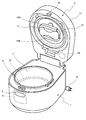
- FIG. 2 is a schematic perspective view of the rice cooker when the lid is opened.
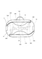
- FIG. 3 is a schematic bottom view of the rotating body of the rice cooker.
- FIG. 4 is a schematic perspective view for explaining the stirring state of the first and second stirring arms.
- FIG. 5 is a control block diagram of the rice cooker.
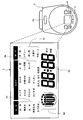
- FIG. 6 is a schematic top view of the rice cooker.
- FIG. 7 is a diagram displayed by the internal state display unit.
- FIG. 8 is another view displayed by the internal state display unit.
- FIG. 9 is another view displayed by the internal state display unit.
- FIG. 10 is another view displayed by the internal state display unit.
- FIG. 11 is another view displayed by the internal state display unit.
- FIG. 12 is another view displayed by the internal state display unit.
- FIG. 13 is another view displayed by the internal state display unit.
- FIG. 14 is another view displayed by the internal state display unit.
- FIG. 15 is another view displayed by the internal state display unit.
- FIG. 16 is a diagram displayed by a modification of the internal state display unit.
- FIG. 17 is a diagram of a modification of the liquid crystal display unit.
- FIG. 1 is a schematic perspective view of a rice cooker according to an embodiment of the present invention viewed obliquely from above.
- the rice cooker includes a rice cooker body 1 as an example of a heating cooker body, and a lid 2 attached to the rice cooker body 1 so as to be openable and closable.
- An open button 3 for opening the lid 2 is provided on the front surface of the rice cooker body 1.
- the tip of the power cord 4 protrudes from the rear surface of the rice cooker body 1. Most of the power cord 4 is wound around a cord reel (not shown) in the rice cooker body 1 so that it can be pulled out.
- the front part of the upper surface of the lid 2 is provided with a liquid crystal display unit 5 for displaying a cooking method, a cooking name, and the like, and a plurality of operation buttons 6, 6,.
- the steam in the inner pot 7 (see FIG. 2) is discharged from the steam outlet 2a at the rear of the upper surface of the lid 2.
- the liquid crystal display unit 5 is an example of a display unit.
- FIG. 2 is a schematic perspective view of the rice cooker with the lid 2 opened.
- the rice cooker body 1 contains an inner pot 7, and rice or water as an example of a heated object enters the inner pot 7. Further, a locked portion 8 is provided at the front portion of the upper surface of the rice cooker body 1. A locking portion 23 provided at the front portion of the lower surface of the lid 2 is releasably locked to the locked portion 8. In addition, a lock mechanism 9 that locks the lid 2 is provided in the rice cooker body 1. When the lock mechanism 9 is not locking the lid 2, when the open button 3 is pressed, the locked portion 8 moves rearward and the locking of the locking portion 23 with respect to the locked portion 8 is released.
- an induction heating coil 10 for induction heating the inner pot 7 is installed in the rice cooker body 1.
- the induction heating coil 10 is an example of a heating unit.
- the inner pan 7 is formed of a high heat conductive member such as aluminum, and a magnetic material such as stainless steel is attached to the outer surface of the inner pan 7 to improve heating efficiency. It is coated.
- the lid body 2 includes an outer lid 21 positioned on the side opposite to the inner pot 7 side when the lid body 2 is closed, and an inner lid 22 positioned on the inner pot 7 side when the lid body 2 is closed.
- a drive motor 24 is installed in the right corner of the rear portion of the outer lid 21.
- a connecting shaft (not shown) is rotatably installed in the central portion of the outer lid 21. The connecting shaft rotates by receiving the rotational driving force generated by the drive motor 24 via a pulley (not shown) and a belt (not shown).
- a rotating body 11 is rotatably arranged between the rice cooker body 1 and the lid body 2.
- the rotating body 11 is detachably attached to the lid body 2. More specifically, one end of the rotating shaft 15 protrudes from the portion of the rotating body 11 on the lid 2 side (see FIG. 4).
- One end of the rotating shaft 15 is detachably connected to the connecting shaft of the outer lid 21 and rotates integrally with the connecting shaft.
- the rotating shaft 15 is rotatable with respect to the rotating body 11.
- the first and second stirring arms 12A and 12B are attached to the rotating body 11.
- the first and second stirring arms 12A and 12B are adjacent to the rotating body 11 in the radial direction, and are separated from the stirring state in contact with the rice in the inner pot 7 and the rice in the inner pot 7. Switching between the non-stirring state is possible. That is, each of the first and second stirring arms 12A and 12B has one end rotatably attached to the rotating body 11, and the other end separated from the rotating body 11 or attached to the rotating body 11. It is possible to approach.
- the first and second stirring arms 12A and 12B are examples of stirring bodies.
- FIG. 3 is a schematic view of the rotating body 11 as viewed from the inner pot 7 side.
- the rotating body 11 has a lid member 13 and an inner pan member 14 detachably attached to the surface of the lid member 13 on the inner pan 7 side. Between the lid side member 13 and the inner pan side member 14, the first and second stirring arm umbrella gears 30, the first stirring arm gears 31A, 32A, 33A, and the second stirring arm gears 31B, 32B are provided. , 33B.
- the rotational drive of the rotary shaft 15 is transmitted to the first stirring arm rotation shaft 34A via the first and second stirring arm umbrella gears 30 and the first stirring arm gears 31A, 32A, 33A, and It is transmitted to the second stirring arm rotating shaft 34B via the second stirring arm umbrella gear 30 and the second stirring arm gears 31B, 32B, 33B.
- FIG. 4 illustration of the rice cooker main body 1 and the cover body 2 is abbreviate
- FIG. 5 is a control block diagram of the rice cooker. In FIG. 5, only main components are shown, and other components are not shown.
- the rice cooker includes a control unit 41 including a microcomputer and an input / output circuit.
- the control unit 41 controls the liquid crystal display unit 5, the drive motor 24, the induction heating coil inverter circuit 51, and the like based on signals from the operation buttons 6, 6,..., The lock mechanism 9, and the temperature sensor 52.
- the induction heating coil inverter circuit 51 is installed in the rice cooker body 1 and causes the induction heating coil 10 to generate an alternating magnetic field.
- the temperature sensor 52 is also installed in the rice cooker body 1 and sends a signal indicating the temperature of the inner pot 7 to the control unit 41.
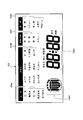
- FIG. 6 is a schematic top view of the rice cooker as viewed from above. A part of FIG. 6 is an enlarged view of the liquid crystal display unit 5. In this enlarged view, all characters and figures that can be displayed by the liquid crystal display unit 5 are shown.
- the liquid crystal display unit 5 includes a rice display unit 5a, a cooking method display unit 5b, a cooking display unit 5c, an internal state display unit 5d, and a time display unit 5e.
- the rice display unit 5a displays one of “white rice”, “unwashed rice”, “brown rice”, “germinated brown rice”, and “separated rice”.
- the cooking method display section 5b displays “normal”, “hard”, “soft”, “oisagi”, “rice porridge”, “Chinese gourd”, “cooking”, “sushi”, “small amount”, “ One of “eco-cooking rice” and “rice cake” is displayed.
- the cooking display unit 5c displays one of “boiled food”, “stew”, “steamed food”, “confectionery”, “reservation 1”, and “reservation 2”.
- the display of the rice display unit 5a, the cooking display unit 5b, and the cooking display unit 5c changes according to the operation of the operation buttons 6, 6,.
- the display of the internal state display unit 5d changes according to the state of the rotating body 11 and the first and second stirring arms 12A and 12B.
- the display of the time display part 5e changes with progress of time or a cooking process.
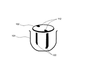
- 7 to 15 are diagrams for explaining one display example of the internal state display unit 5d.
- the internal state display unit 5d visually notifies the rotary body 11 and the first and second stirring arms 12A and 12B. Specifically, the internal state display unit 5d displays the diagram shown in FIG. 7 when the first and second stirring arms 12A and 12B are in the non-stirring state when the lid 2 is closed, If the first and second stirring arms 12A and 12B are in the stirring state when the lid 2 is closed, the diagram shown in FIG. 8 is displayed. Further, when the rotating body 11 rotates while the lid 2 is closed and the first and second stirring arms 12A and 12B are in the stirring state, the internal state display portion 5d is displayed in FIGS. 10, 11, 8, 9, 10, 11, 8,... Are sequentially displayed.
- FIGS. The diagrams shown in FIG. 13, FIG. 14, FIG. 7, FIG. 12, FIG. 13, FIG.
- 101 is an inner pot corresponding portion
- 102 is a rotating body corresponding portion
- 111 to 114 are upper stirring arm corresponding portions
- 121 to 124 are lower stirring arm corresponding portions.
- the drive unit 20 rotates the rotating shaft 15 forward (as viewed from the lid 2 side).
- the first and second stirring arms 12A and 12B can be rotated to the stirring state shown in FIG.
- the first and second stirring arms 12A and 12B in the stirring state can be rotated integrally with the rotating body 11 by continuing to rotate the rotating shaft 15 forward.
- rice and water in the inner pot 10 can be stirred by the first and second stirring arms 12A and 12B.
- the drive unit 20 rotates the rotating shaft 15 in the reverse direction (counterclockwise as viewed from the lid 2 side).
- the first and second stirring arms 12A and 12B can be rotated to the non-stirring state shown in FIGS. Thereby, it can prevent that the 1st, 2nd stirring arm 12A, 12B obstructs opening and closing of the cover body 2.
- FIG. 1st, 2nd stirring arm 12A, 12B obstructs opening and closing of the cover body 2.
- the rotation of the first and second stirring arms 12A and 12B and the rotation of the rotating body 11 can be performed by one drive motor 24.
- the first and second stirring arms 12A and 12B are in the non-stirring state of FIGS. 2 and 3 according to the display of the internal state display portion 5d, or It can be visually discriminated whether the stirring state shown in FIG. Therefore, when the first and second stirring arms 12A and 12B are in the stirring state, the user can be discouraged from opening the lid 2. As a result, the possibility that the first and second stirring arms 12A and 12B wind up the rice in the inner pan 7 and the opening operation of the lid 2 is hindered by the first and second stirring arms 12A and 12B is reduced. it can.
- the state of the first and second stirring arms 12A and 12B is visually notified by the internal state display unit 5d, even if the surroundings are noisy, the user can check the state of the first and second stirring arms 12A and 12B. Can be reliably determined.
- FIGS. 8, 9, 10, 11, 8, 8, 9, 10, 11, 8, When the rotating body 11 is rotating, the internal state display 5d is shown in FIGS. 8, 9, 10, 11, 8, 8, 9, 10, 11, 8,.
- the figures are sequentially displayed, and the figures shown in FIGS. 7, 12, 13, 14, 7, 12, 12, 13, 14, 7,... Are sequentially displayed. Therefore, when there is a possibility that the rotating body 11 or the like may be damaged by opening the lid 2, the user can be reminded of opening the lid 2.
- the induction heating coil 10 is used as an example of a heating unit.
- a resistance heater may be used as an example of a heating unit.
- one end of the first and second stirring arms 12A and 12B is rotatably attached to the rotating body 11, but the rotating body 11 includes the first and second stirring arms 12A and 12B. Only one of the ends may be pivotably attached. That is, in the present invention, the number of stirring bodies is not limited to two, but may be one, for example.
- the liquid crystal display unit 5 visually notifies the rotary body 11 and the first and second stirring arms 12A and 12B.
- the notification related to the stirring arms 12A and 12B may be made audibly. For example, when the first and second stirring arms 12A and 12B are in the stirring state, music may flow from a speaker.
- the liquid crystal display unit 5 has the internal state display unit 5d.
- the lock mechanism 9 does not lock the lid 2
- an internal state display unit for displaying the diagrams shown in FIGS. 15 and 16 may be provided. Since it is possible to determine whether or not the lock mechanism 9 has locked the lid body 2 by this internal state display section, the lock mechanism 9 does not lock the lid body 2 and the first and second stirring arms 12A , 12B can be opened and the user can be discouraged from opening the lid 2 when it is in a stirring state.
- 101 is an inner pan corresponding part
- 102 is a rotating body corresponding part
- 103 is a locked state cover corresponding part
- 111 is an upper stirring arm corresponding part
- 121 is a lower stirring arm corresponding part. is there.
- liquid crystal display unit 5 that displays the rice cooking process associated with the stirring state and the non-stirring state may be used.
- the liquid crystal display unit 105 shown in FIG. 17 may be provided on the upper surface of the lid 2.
- the liquid crystal display unit 105 includes a rice cooking process display unit 105f in addition to the rice display unit 105a, the cooking method display unit 105b, the cooking display unit 105c, the internal state display unit 105d, and the time display unit 105e.
- This rice cooking process display unit 105f displays one of “washed rice”, “preheating”, “boiling”, and “purple” during rice cooking.
- the internal state display unit 105d displays the stirring state and the non-stirring state associated with the process related to the display of the rice cooking process display unit 105f.
- FIG. 17 shows all characters and figures that can be displayed by the liquid crystal display unit 105, as in FIG. Moreover, the rice display part 105a, the cooking display part 105b, the cooking display part 105c, the internal state display part 105d, and the time display part 105e in FIG. 17 are the rice display part 5a, the cooking display part 5b, and the cooking display part in FIG. Since it is the same part as 5c, the internal state display part 5d, and the time display part 5e, description is abbreviate
- liquid crystal display unit 5 of the above embodiment a liquid crystal display unit having only the rice display unit 105a, the cooking method display unit 105b, the internal state display unit 105d, the time display unit 105e, and the rice cooking process display unit 105f may be used. .
- a rotary encoder that detects the rotation speed of the connecting shaft may be provided in the lid 2 and the state of the rotary body 11 may be detected based on the output of the rotary encoder.
- a limit switch that is turned on by the first and second stirring arms 12A and 12B in the non-stirring state is provided in the rotating body 11, and the first and second stirring are performed based on the output of the limit switch.
- the state of the arms 12A and 12B may be detected.
Landscapes
- Engineering & Computer Science (AREA)
- Food Science & Technology (AREA)
- Manufacturing & Machinery (AREA)
- Cookers (AREA)
Abstract
Description
被加熱物を収容する内鍋と、
上記内鍋が収納される加熱調理器本体と、
上記加熱調理器本体に取り付けられ、上記被加熱物を加熱するための加熱部と、
上記加熱調理器本体の上部に開閉可能に取り付けられ、上記内鍋を覆うように閉じることが可能な蓋体と、
上記加熱調理器本体と上記蓋体との間に回転可能に配置された回転体と、
上記回転体に取り付けられて、上記内鍋内の被加熱物に接触した攪拌状態と、上記内鍋内の被加熱物から乖離した非攪拌状態とを切替可能な攪拌体と、
上記蓋体が閉じられた状態において、上記攪拌体が上記攪拌状態と上記非攪拌状態とのどちらになっているかを報知する報知部と
を備えることを特徴としている。
上記報知部は、上記攪拌体に係る報知を視覚的に行う表示部である。
上記表示部は、上記攪拌状態および上記非攪拌状態に関連付けされた炊飯工程を表示する。
上記蓋体をロックするロック機構を備え、
上記表示部は、上記ロック機構が上記蓋体をロックしているか否かを表示する。
上記表示部は、上記回転体が回転している状態を表示する。
2…蓋体
5…液晶表示部
9…ロック機構
10…誘導加熱コイル
11…回転体
12A…第1攪拌アーム
12B…第2攪拌アーム
Claims (5)
- 被加熱物を収容する内鍋(7)と、
上記内鍋(7)が収納される加熱調理器本体(1)と、
上記加熱調理器本体(1)に取り付けられ、上記被加熱物を加熱するための加熱部(10)と、
上記加熱調理器本体(1)の上部に開閉可能に取り付けられ、上記内鍋(7)を覆うように閉じることが可能な蓋体(2)と、
上記加熱調理器本体(1)と上記蓋体(2)との間に回転可能に配置された回転体(11)と、
上記回転体(11)に取り付けられて、上記内鍋(7)内の被加熱物に接触した攪拌状態と、上記内鍋(7)内の被加熱物から乖離した非攪拌状態とを切替可能な攪拌体(12A,12B)と、
上記蓋体(2)が閉じられた状態において、上記攪拌体(12A,12B)が上記攪拌状態と上記非攪拌状態とのどちらになっているかを報知する報知部(5)と
を備えることを特徴とする加熱調理器。 - 請求項1に記載の加熱調理器において、
上記報知部(5)は、上記攪拌体(12A,12B)に係る報知を視覚的に行う表示部(5)であることを特徴とする加熱調理器。 - 請求項2に記載の加熱調理器において、
上記表示部(5)は、上記攪拌状態および上記非攪拌状態に関連付けされた炊飯工程を表示することを特徴とする加熱調理器。 - 請求項2または3に記載の加熱調理器において、
上記蓋体(2)をロックするロック機構(9)を備え、
上記表示部(5)は、上記ロック機構(9)が上記蓋体(2)をロックしているか否かを表示することを特徴とする加熱調理器。 - 請求項2から4までのいずれか一項に記載の加熱調理器において、
上記表示部(5)は、上記回転体(11)が回転している状態を表示することを特徴とする加熱調理器。
Priority Applications (3)
| Application Number | Priority Date | Filing Date | Title |
|---|---|---|---|
| CN201380007343.4A CN104080376B (zh) | 2012-02-15 | 2013-02-14 | 加热烹调器 |
| US14/378,815 US10694881B2 (en) | 2012-02-15 | 2013-02-14 | Consumer heating cooker with pictures notifying pivotable stirring blades stirring and non-stirring state |
| JP2013558731A JP5771706B2 (ja) | 2012-02-15 | 2013-02-14 | 加熱調理器 |
Applications Claiming Priority (2)
| Application Number | Priority Date | Filing Date | Title |
|---|---|---|---|
| JP2012-030691 | 2012-02-15 | ||
| JP2012030691 | 2012-02-15 |
Publications (1)
| Publication Number | Publication Date |
|---|---|
| WO2013122153A1 true WO2013122153A1 (ja) | 2013-08-22 |
Family
ID=48984262
Family Applications (1)
| Application Number | Title | Priority Date | Filing Date |
|---|---|---|---|
| PCT/JP2013/053548 Ceased WO2013122153A1 (ja) | 2012-02-15 | 2013-02-14 | 加熱調理器 |
Country Status (4)
| Country | Link |
|---|---|
| US (1) | US10694881B2 (ja) |
| JP (1) | JP5771706B2 (ja) |
| CN (1) | CN104080376B (ja) |
| WO (1) | WO2013122153A1 (ja) |
Families Citing this family (9)
| Publication number | Priority date | Publication date | Assignee | Title |
|---|---|---|---|---|
| CN205458000U (zh) * | 2015-12-25 | 2016-08-17 | 佛山市顺德区爱德实业有限公司 | 一种多功能烹调锅 |
| CN105942869B (zh) * | 2015-12-31 | 2018-02-09 | 九阳股份有限公司 | 一种炒菜机 |
| CN208447213U (zh) * | 2018-01-17 | 2019-02-01 | 宁波锦宇电器有限公司 | 一种多功能慢炖锅 |
| CN108354439A (zh) * | 2018-02-05 | 2018-08-03 | 岭南师范学院 | 一种全自动电饭煲及其控制方法 |
| CN108577498B (zh) * | 2018-05-15 | 2022-01-07 | 上海景博厨房用具有限公司 | 一种具有恒温储米功能的智能电饭煲 |
| USD1059936S1 (en) | 2019-03-14 | 2025-02-04 | StoreBound LLC | Cup |
| USD965376S1 (en) | 2019-08-08 | 2022-10-04 | StoreBound LLC | Cooking appliance |
| CN111179616A (zh) * | 2020-01-06 | 2020-05-19 | 中徽建技术有限公司 | 一种用于智能交通的信号指挥设备 |
| US20210244228A1 (en) * | 2020-02-10 | 2021-08-12 | StoreBound LLC | Cooking apparatus |
Citations (5)
| Publication number | Priority date | Publication date | Assignee | Title |
|---|---|---|---|---|
| JPH07289424A (ja) * | 1994-04-21 | 1995-11-07 | Tsutomu Nojo | 全自動炊飯器 |
| JPH10108786A (ja) * | 1996-10-07 | 1998-04-28 | Fuji Seiki Kk | 自動炊きむら防止装置 |
| JP2004188030A (ja) * | 2002-12-12 | 2004-07-08 | Kubota Corp | 無洗米用炊飯装置 |
| JP2004321307A (ja) * | 2003-04-22 | 2004-11-18 | Toshiba Home Technology Corp | 調理器 |
| JP2008278924A (ja) * | 2007-05-08 | 2008-11-20 | Matsushita Electric Ind Co Ltd | 炊飯器 |
Family Cites Families (8)
| Publication number | Priority date | Publication date | Assignee | Title |
|---|---|---|---|---|
| AU600181B2 (en) * | 1987-12-23 | 1990-08-02 | Food Automation-Service Techniques, Inc. | Stir prompt apparatus |
| JP3961109B2 (ja) * | 1998-04-13 | 2007-08-22 | エムケー精工株式会社 | 製パン機 |
| US6784404B2 (en) * | 2000-07-12 | 2004-08-31 | Whirlpool Corporation | System for controlling the duration of a self-clean cycle in an oven |
| HK1045056A2 (en) * | 2001-09-03 | 2002-11-01 | 陈永坚 | Domestic appliances |
| US8555206B2 (en) * | 2007-12-21 | 2013-10-08 | Fisher-Rosemount Systems, Inc. | Methods and apparatus to present recipe progress status information |
| CN101461655A (zh) * | 2009-01-09 | 2009-06-24 | 聂怀军 | 一种全自动烹饪系统 |
| AU2011240145B2 (en) * | 2010-04-12 | 2016-03-17 | Aktiebolaget Electrolux | A control interface for household appliances |
| CN201948782U (zh) * | 2011-01-11 | 2011-08-31 | 徐国仪 | 锅盖带搅拌装置的煮汤且保温锅 |
-
2013
- 2013-02-14 CN CN201380007343.4A patent/CN104080376B/zh not_active Expired - Fee Related
- 2013-02-14 US US14/378,815 patent/US10694881B2/en not_active Expired - Fee Related
- 2013-02-14 JP JP2013558731A patent/JP5771706B2/ja not_active Expired - Fee Related
- 2013-02-14 WO PCT/JP2013/053548 patent/WO2013122153A1/ja not_active Ceased
Patent Citations (5)
| Publication number | Priority date | Publication date | Assignee | Title |
|---|---|---|---|---|
| JPH07289424A (ja) * | 1994-04-21 | 1995-11-07 | Tsutomu Nojo | 全自動炊飯器 |
| JPH10108786A (ja) * | 1996-10-07 | 1998-04-28 | Fuji Seiki Kk | 自動炊きむら防止装置 |
| JP2004188030A (ja) * | 2002-12-12 | 2004-07-08 | Kubota Corp | 無洗米用炊飯装置 |
| JP2004321307A (ja) * | 2003-04-22 | 2004-11-18 | Toshiba Home Technology Corp | 調理器 |
| JP2008278924A (ja) * | 2007-05-08 | 2008-11-20 | Matsushita Electric Ind Co Ltd | 炊飯器 |
Also Published As
| Publication number | Publication date |
|---|---|
| US20150020694A1 (en) | 2015-01-22 |
| CN104080376A (zh) | 2014-10-01 |
| CN104080376B (zh) | 2016-03-23 |
| US10694881B2 (en) | 2020-06-30 |
| JP5771706B2 (ja) | 2015-09-02 |
| JPWO2013122153A1 (ja) | 2015-05-18 |
Similar Documents
| Publication | Publication Date | Title |
|---|---|---|
| JP5771706B2 (ja) | 加熱調理器 | |
| JP6641157B2 (ja) | 加熱調理器 | |
| JP5269227B1 (ja) | 加熱調理器 | |
| JP2018192207A (ja) | 加熱調理器 | |
| JP2013165822A (ja) | 炊飯器 | |
| CN105517465B (zh) | 加热烹调器 | |
| JP5781963B2 (ja) | 炊飯器 | |
| JP6054082B2 (ja) | 加熱調理器 | |
| JP6007038B2 (ja) | 加熱調理器 | |
| JP2013223597A (ja) | 加熱調理器 | |
| JP5894034B2 (ja) | 加熱調理機 | |
| TWI634863B (zh) | 攪拌單元、加熱調理器 | |
| JP6016493B2 (ja) | 電子調理機器 | |
| JP7646510B2 (ja) | 調理器、調理方法 | |
| JP2014018551A (ja) | 電子機器 | |
| JP7646511B2 (ja) | 調理器、調理方法 | |
| JP2013226203A (ja) | 加熱調理器 | |
| JP5947150B2 (ja) | 加熱調理器 | |
| JP2013244052A (ja) | 炊飯器 | |
| JP2023082485A (ja) | 加熱調理器 | |
| JP2022176720A (ja) | 調理器、調理器が備える回転体の回転制御方法 | |
| JP2016101534A (ja) | 加熱調理機 | |
| JP5826080B2 (ja) | 加熱調理器 | |
| JP2014030591A (ja) | 加熱調理器 |
Legal Events
| Date | Code | Title | Description |
|---|---|---|---|
| WWE | Wipo information: entry into national phase |
Ref document number: 201380007343.4 Country of ref document: CN |
|
| 121 | Ep: the epo has been informed by wipo that ep was designated in this application |
Ref document number: 13749144 Country of ref document: EP Kind code of ref document: A1 |
|
| ENP | Entry into the national phase |
Ref document number: 2013558731 Country of ref document: JP Kind code of ref document: A |
|
| WWE | Wipo information: entry into national phase |
Ref document number: 14378815 Country of ref document: US |
|
| NENP | Non-entry into the national phase |
Ref country code: DE |
|
| 122 | Ep: pct application non-entry in european phase |
Ref document number: 13749144 Country of ref document: EP Kind code of ref document: A1 |