WO2013118253A1 - センサ状態判断システム - Google Patents
センサ状態判断システム Download PDFInfo
- Publication number
- WO2013118253A1 WO2013118253A1 PCT/JP2012/052725 JP2012052725W WO2013118253A1 WO 2013118253 A1 WO2013118253 A1 WO 2013118253A1 JP 2012052725 W JP2012052725 W JP 2012052725W WO 2013118253 A1 WO2013118253 A1 WO 2013118253A1
- Authority
- WO
- WIPO (PCT)
- Prior art keywords
- sensor
- detection sensor
- value
- signal
- state
- Prior art date
Links
Images


Classifications
-
- G—PHYSICS
- G01—MEASURING; TESTING
- G01P—MEASURING LINEAR OR ANGULAR SPEED, ACCELERATION, DECELERATION, OR SHOCK; INDICATING PRESENCE, ABSENCE, OR DIRECTION, OF MOVEMENT
- G01P21/00—Testing or calibrating of apparatus or devices covered by the preceding groups
-
- B—PERFORMING OPERATIONS; TRANSPORTING
- B61—RAILWAYS
- B61F—RAIL VEHICLE SUSPENSIONS, e.g. UNDERFRAMES, BOGIES OR ARRANGEMENTS OF WHEEL AXLES; RAIL VEHICLES FOR USE ON TRACKS OF DIFFERENT WIDTH; PREVENTING DERAILING OF RAIL VEHICLES; WHEEL GUARDS, OBSTRUCTION REMOVERS OR THE LIKE FOR RAIL VEHICLES
- B61F5/00—Constructional details of bogies; Connections between bogies and vehicle underframes; Arrangements or devices for adjusting or allowing self-adjustment of wheel axles or bogies when rounding curves
- B61F5/02—Arrangements permitting limited transverse relative movements between vehicle underframe or bolster and bogie; Connections between underframes and bogies
- B61F5/22—Guiding of the vehicle underframes with respect to the bogies
- B61F5/24—Means for damping or minimising the canting, skewing, pitching, or plunging movements of the underframes
-
- G—PHYSICS
- G01—MEASURING; TESTING
- G01D—MEASURING NOT SPECIALLY ADAPTED FOR A SPECIFIC VARIABLE; ARRANGEMENTS FOR MEASURING TWO OR MORE VARIABLES NOT COVERED IN A SINGLE OTHER SUBCLASS; TARIFF METERING APPARATUS; MEASURING OR TESTING NOT OTHERWISE PROVIDED FOR
- G01D3/00—Indicating or recording apparatus with provision for the special purposes referred to in the subgroups
- G01D3/08—Indicating or recording apparatus with provision for the special purposes referred to in the subgroups with provision for safeguarding the apparatus, e.g. against abnormal operation, against breakdown
Definitions
- the present invention relates to a sensor state determination system that determines whether or not an acceleration sensor or the like used in a railway vehicle is in an abnormal state while the railway vehicle is running.
- an acceleration sensor or the like is used in a vibration suppression control system that actively controls a damper device, a state monitoring system that monitors a state of a component or a ride comfort, and the like.
- the acceleration sensor detects vibration acceleration acting on the vehicle body, and the control means appropriately determines the damping force generated by the damper device based on the detected vibration acceleration, so that the active damper control is performed. Executed.
- active damper control is executed based on the detected vibration acceleration under the assumption that the acceleration sensor is in a normal state, and the acceleration sensor itself.
- the case where is broken is not considered. That is, when the acceleration sensor itself is out of order, the active damper control is executed based on the signal of the acceleration sensor in an abnormal state, so that the vibration suppression control is not properly executed. Accordingly, it is desired to first accurately determine whether or not the acceleration sensor is in an abnormal state.
- the present invention can accurately determine whether a detection sensor such as an acceleration sensor used in a railway vehicle is in an abnormal state while the railway vehicle is running.
- An object is to provide a sensor state determination system.
- a sensor state determination system determines whether or not a detection sensor capable of detecting a physical value acting on a railway vehicle is in an abnormal state while the railway vehicle is running.
- a monitoring sensor equivalent to the detection sensor is attached to a part equivalent to the part where the detection sensor is attached, and the first signal detected by the detection sensor and the first signal detected by the monitoring sensor are detected.
- the determination unit of the sensor state determination system determines that the detection sensor is in an abnormal state when the case where the coherence value is smaller than the abnormality determination value is continuously established a plurality of times.
- the determination means of the sensor state determination system is configured such that the detection sensor is in an abnormal state when the coherence value is always smaller than a preset normal determination value in a short time after the railcar starts traveling. It is preferable to judge that.
- a monitoring sensor equivalent to the detection sensor is attached to a part equivalent to the part where the detection sensor is attached, and the coherence indicating the correlation between the first signal and the second signal.
- the value is smaller than the abnormality determination value, it is determined that the detection sensor is in an abnormal state. That is, the shapes of the first signal and the second signal are compared based on the coherence value, and it is determined whether or not the detection sensor is in an abnormal state. For this reason, a strict comparison between the first signal and the second signal can be performed, and it can be accurately determined whether or not the detection sensor is in an abnormal state.
- FIG. 1 is a front view conceptually showing a railway vehicle 1 to which a sensor state determination system 50 is applied.
- a vehicle body 30 is mounted on two carriages 10 provided in the front-rear direction via an air spring 20, and a damper device 40 that attenuates left and right vibrations acting on the vehicle body 30 is provided.
- the damper device 40 is configured so that the damping force generated can be adjusted by adjusting the opening amount of a solenoid valve (not shown) by a damper control command value F input from the electronic control device 60.
- the sensor state determination system 50 determines the state of the acceleration sensor. As shown in FIG. 1, the sensor state determination system 50 can output a detection sensor 51 that is an acceleration sensor that can detect vibration acceleration acting on the vehicle body 30, and can output the same value as the detection sensor 51.
- a monitoring sensor 52 which is an equivalent acceleration sensor, and the electronic control unit 60 described above are included.
- the detection sensor 51 is provided for executing active damper control, and outputs the vibration acceleration acting on the vehicle body 30 to the electronic control unit 60 as the first signal X.
- the monitoring sensor 52 is provided to monitor the detection sensor 51 and outputs the vibration acceleration acting on the vehicle body 30 to the electronic control unit 60 as the second signal Y.
- the electronic control device 60 is provided with a control command value calculation unit 61 for calculating a damper control command value F.
- the control command value calculation unit 61 calculates an optimum damper control command value F based on the first signal X input from the detection sensor 51 when left-right vibration is generated in the vehicle body 30, and this damper control command value F Is output to the damper device 40. As a result, the damper device 40 positively generates a damping force and the active damper control is executed.
- the active damper control is executed based on the normal first signal X. Therefore, the vibration suppression control is appropriately executed and the ride comfort is improved.
- the detection sensor 51 is abnormal (failed)
- the active damper control is executed based on the abnormal first signal X, so that the vibration suppression control is not properly executed and the ride comfort is reduced.
- the case where the detection sensor 51 is in an abnormal state includes, for example, a case where the connector of the detection sensor 51 is loose, a case where the wiring of the detection sensor 51 is disconnected, and the like.
- the monitoring sensor 52 in order to determine whether or not the detection sensor 51 is in an abnormal state, is attached to the same part as the detection sensor 51 as described above, and the electronic control device 60 is provided with a coherence calculation unit 62 and a state determination unit 63 as determination means.
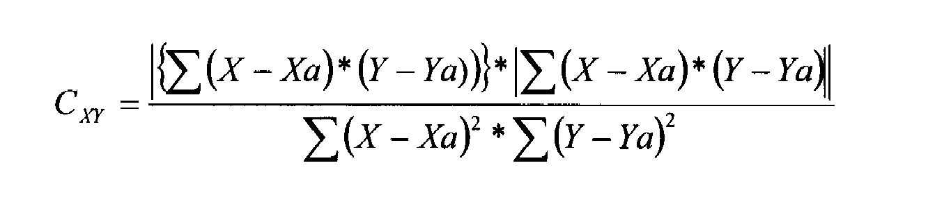
- the coherence calculation unit 62 calculates a coherence value CXY indicating the correlation between both signals based on the first signal X and the second signal Y.
- the coherence value C (f) is a value indicating how much correlation there is between two signals x (t) and y (t), and is defined by Equation (1).
- Sxy (f) is a cross spectrum between x (t) and y (t), and is a result of Fourier transform of the cross-correlation function between x (t) and y (t).
- Sx (f) is the power spectrum of x (t), and is the result of Fourier transform of the autocorrelation function of x (t).
- Sy (f) is a power spectrum of y (t), which is a Fourier transform of the autocorrelation function of y (t).
- t is time and f is frequency.
- the coherence computing unit 62 computes a coherence value CXY between the first signal X and the second signal Y using the formula (2) obtained by expanding the formula (1).
- a first signal X detected every 4 milliseconds detected by the detection sensor 51 is input to X represented by the equation (2), and a monitoring sensor is represented to Y represented by the equation (2).
- the second signal Y detected every 4 milliseconds detected by 52 is input.
- Xa represented by the equation (2) is an average value of the first signal X every 0.1 seconds
- Ya represented by the equation (2) is a second value every 0.1 seconds. The average value of the signal Y.
- the time during which the first signal X and the second signal Y are input is not limited to every 4 milliseconds, and can be changed as appropriate. Further, the time interval for calculating the average values Xa and Ya is not limited to every 0.1 second, but is appropriately changed depending on the size of the frequency.
- the coherence value CXY calculated by the equation (2) is a value from 0 to 1, and is 1 when the first signal X and the second signal Y completely coincide with each other. 0 when there is no correlation in signal Y.
- the coherence value CXY is a value indicating how similar the shape of the first signal X and the second signal Y is every 0.1 second.
- the state determination unit 63 monitors the coherence value CXY calculated every 0.1 second, and determines whether or not the coherence value CXY is smaller than the abnormality determination value 0.6. If the coherence value CXY is 0.6 or more, the state determination unit 63 determines that the shape of the first signal X is similar to the shape of the second signal Y, and the detection sensor 51 is in a normal state. Judge. On the other hand, if the coherence value CXY is smaller than 0.6, the state determination unit 63 determines that the shape of the first signal X is not similar to the shape of the second signal, and the detection sensor 51 is in an abnormal state. Judge that
- the state determination unit 63 determines that the detection sensor 51 is in an abnormal state when the case where the coherence value CXY is smaller than 0.6 is continuously established N (for example, 10 times). It is comprised so that it may be judged. This is because the coherence value CXY is smaller than 0.6 only once due to the influence of noise input to the detection sensor 51 and the monitoring sensor 52, and it is determined that the detection sensor 51 is in an abnormal state. This is to prevent this.
- the state determination unit 63 determines whether or not the coherence value CXY is always smaller than a predetermined normal determination value of 0.8 in a short time (for example, 10 seconds) when the railcar 1 starts traveling. It is configured as such. This is to determine whether or not the detection sensor 51 is in a normal state immediately after the railcar 1 starts traveling. Further, the state determination unit 63 is configured to determine whether or not the detection sensor 51 is in an abnormal state based on the coherence value CXY only when the railway vehicle 1 is traveling. This is because when the railway vehicle 1 is stopped, the values of the first signal X and the second signal Y are originally “0”, and the coherence value CXY is not calculated.
- the state determination unit 63 is configured to output a normal signal ⁇ to the notification means 70 when it is determined that the detection sensor 51 is in a normal state. Based on the normal signal ⁇ , the notification means 70 notifies the driver or the like that the detection sensor 51 is in a normal state, for example, by turning on a blue lamp. On the other hand, the state determination unit 63 is configured to output an abnormal signal ⁇ to the notification unit 70 when it is determined that the detection sensor 51 is in an abnormal state. Based on this abnormal signal ⁇ , the notification means 70 notifies the driver or the like that the detection sensor 51 is in an abnormal state, for example, by turning on a red lamp.
- the state determination unit 63 is configured to output the OFF signal ⁇ to the control command value calculation unit 61 only when it is determined that the detection sensor 51 is in an abnormal state. Based on the OFF signal ⁇ , the control command value calculation unit 61 sets the damper control command value F to “0” so as to prohibit the active damper control, and the damper device 40 enters the passive state.
- FIG. 3 shows the relationship between the elapsed time t from when the railway vehicle 1 starts traveling and the X signal detected by the detection sensor 51.
- FIG. 4 shows the relationship between the elapsed time t and the Y signal detected by the monitoring sensor 52.
- FIG. 5 shows the relationship between the elapsed time t and the coherence value CXY.
- FIG. 6 shows the relationship between the elapsed time t and the traveling speed V of the railway vehicle 1.
- FIG. 7 shows the relationship between the elapsed time t and the normal signal ⁇ or the abnormal signal ⁇ output from the state determination unit 63.
- the state determination unit 63 determines that the detection sensor 51 is in a normal state and outputs a normal signal ⁇ to the notification means 70 as shown in FIG. Therefore, immediately after the railway vehicle 1 starts traveling, it is possible to notify the driver or the like that the detection sensor 51 is not initially defective.
- the state determination unit 63 determines whether or not the detection sensor 51 is in an abnormal state based on the coherence value CXY. Do not judge. Therefore, at time D, the result of determining that the detection sensor 51 is in a normal state is maintained. Note that the coherence value CXY greatly fluctuates at time D due to the influence of noise input to the detection sensor 51 and the monitoring sensor 52.
- the state determination unit 63 determines that the detection sensor 51 is in an abnormal state, and outputs an abnormal signal ⁇ to the notification unit 70. As a result, an abnormal state of the detection sensor 51 can be notified to the driver or the like. At this time, the state determination unit 63 outputs an OFF signal ⁇ to the control command value calculation unit 61, and the damper device 40 enters a passive state. As a result, when the detection sensor 51 is in an abnormal state, it is possible to prevent the active damper control from being executed and the ride comfort from being deteriorated.
- the detection sensor 51 when the difference in amplitude or power between the first signal X and the second signal Y is not less than the predetermined value without using the coherence value CXY, the detection sensor 51 is A configuration for determining that the state is abnormal is also conceivable. However, in the case of this configuration, since the amplitude or power of the first signal X and the second signal Y at each moment is compared, random noise is input to the detection sensor 51 and the monitoring sensor 52. Sometimes, it is difficult to accurately determine whether or not the detection sensor 51 is in an abnormal state.
- the detection sensor 51 is in an abnormal state when the coherence value CXY indicating the degree of correlation between the first signal X and the second signal Y is smaller than the abnormality determination value.
- the shapes of the first signal X and the second signal Y at a predetermined time are compared. For this reason, it is a case where random noise is input to the detection sensor 51 and the monitoring sensor 52, compared to the case where the amplitude or power of the first signal X and the second signal Y is compared at every moment.
- a strict comparison between the first signal X and the second signal Y can be performed, and it can be accurately determined whether or not the detection sensor 51 is in an abnormal state.
- the coherence value CXY is calculated using the above equation (2).
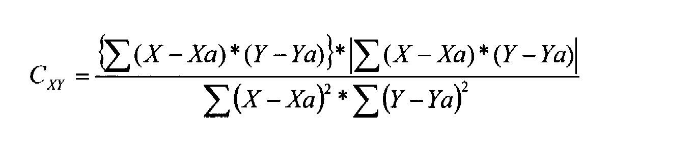
- the equation for calculating the coherence value CXY is not limited to the equation (2). . Therefore, for example, the coherence value CXY may be calculated using the following (Equation 3).
- the above equation (Equation 3) is an equation obtained by removing the absolute value from the molecular equation of the above equation (Equation 2).
- the coherence value CXY is a value from ⁇ 1 to 1, and when the phase is shifted by 180 degrees, the coherence value CXY is a positive predetermined value and a negative predetermined value ( For example, 1 and -1).
- the equation (2) having an absolute value in the molecular formula is used, the coherence value CXY is a value from 0 to 1, and even when the phase is shifted by 180 degrees, the coherence value CXY. Both become positive predetermined values (for example, 1). Therefore, when the equation (3) is used, a negative value of the coherence value CXY based on the phase shift can be taken into consideration, and a strict comparison between the first signal X and the second signal Y is performed. be able to.
- the equation for calculating the coherence value CXY may be the following equation (4) which is simpler than the equation (3).
- the short time A (10 seconds) when the railway vehicle 1 starts traveling the abnormality judgment value (0.6), the normal judgment value (0.8), and the above-described multiple times N (10 times). Is determined in advance by experiments and can be changed as appropriate. Further, the abnormality judgment value and the normal judgment value may coincide with each other.
- the sensor state determination system 50 detects the case where the coherence value CXY is smaller than the abnormality determination value (0.6) once, that is, at time B shown in FIG. It may be determined that the sensor 51 is in an abnormal state.
- the sensor state determination system 50 determines that the detection sensor 51 is in an abnormal state when the case where the coherence value CXY is smaller than the abnormality determination value is continuously established 10 times. For example, if the coherence value CXY is smaller than the abnormality determination value, the sensor state determination system 50 determines that the coherence value CXY is an abnormal state due to a minor failure when it is continuously established 10 times or more and less than 20 times. May be determined to be in an abnormal state due to a serious failure when the value of is less than the abnormality determination value is continuously established 20 times or more.
- the sensor state determination system 50 is configured to determine whether or not the acceleration sensor (detection sensor 51) used in the vibration suppression control system is in an abnormal state.
- the system is used to control whether or not an acceleration sensor used in a state monitoring system that monitors the state or riding comfort of parts of a railway vehicle is in an abnormal state or the control of the vehicle. It may be configured to determine whether or not various sensors are in an abnormal state.
- the detection sensor 51 and the monitoring sensor 52 are acceleration sensors that detect vibration acceleration in the left-right direction, but are acceleration sensors that detect the vertical direction or the front-back direction, or biaxial or triaxial acceleration. It may be a sensor. Further, the detection sensor 51 and the monitoring sensor 52 may be a speed sensor, an angle sensor, an angular speed sensor, a displacement sensor, a pressure sensor, or the like. Further, the detection sensor 51 and the monitoring sensor 52 are attached to the vehicle body 30, but may be attached to any part of the railway vehicle 1.
Abstract
Description

Sxy(f)は、x(t)とy(t)とのクロススペクトルであり、x(t)とy(t)との相互相関関数をフーリエ変換したものである。Sx(f)は、x(t)のパワースペクトルであり、x(t)の自己相関関数をフーリエ変換したものである。Sy(f)は、y(t)のパワースペクトルであり、y(t)の自己相関関数をフーリエ変換したものである。tは時間であり、fは周波数である。
(数2)式で示されたXには、検出用センサ51により検出される4ミリ秒毎の第1信号Xが入力され、(数2)式で示されたYには、監視用センサ52により検出される4ミリ秒毎の第2信号Yが入力される。また、(数2)式で示されたXaは、0.1秒毎の第1信号Xの平均値であり、(数2)式で示されたYaは、0.1秒毎の第2信号Yの平均値である。なお、第1信号X、第2信号Yが入力される時間は、4ミリ秒毎に限定されるものではなく、適宜変更可能である。また、平均値Xa,Yaを演算するための時間間隔は、0.1秒毎に限定されるものではなく、周波数の大きさによって適宜変更するものである。
例えば、上記した実施形態においては、上記した(数2)式を用いてコヒーレンス値CXYを演算したが、コヒーレンス値CXYを演算するための式は、(数2)式に限定されるものではない。従って、例えば、以下に示す(数3)式を用いてコヒーレンス値CXYを演算しても良い。

10 台車
20 空気バネ
30 車体
40 ダンパ装置
50 センサ状態判断システム
51 検出用センサ
52 監視用センサ
60 電子制御装置
61 制御指令値演算部
62 コヒーレンス演算部
63 状態判断部
70 報知手段
Claims (3)
- 鉄道車両に作用する物理値を検出可能な検出用センサが前記鉄道車両の走行中に異常状態になっているか否かを判断するセンサ状態判断システムにおいて、
前記検出用センサが取付けられている部位と同等の部位に前記検出用センサと同等の監視用センサが取付けられ、
前記検出用センサにより検出された第1信号と前記監視用センサにより検出された第2信号とに基づいて両信号の相関関係を示すコヒーレンス値を演算し、このコヒーレンス値が予め設定された異常判断値より小さい場合に前記検出用センサが異常状態になっていると判断する判断手段が設けられていることを特徴とするセンサ状態判断システム。 - 請求項1に記載するセンサ状態判断システムにおいて、
前記判断手段は、前記コヒーレンス値が前記異常判断値より小さい場合が連続して複数回成立したとき、前記検出用センサが異常状態になっていると判断することを特徴とするセンサ状態判断システム。 - 請求項1又は請求項2に記載するセンサ状態判断システムにおいて、
前記判断手段は、前記鉄道車両が走行を開始した短時間において、前記コヒーレンス値が予め設定された正常判断値より常に小さい場合に前記検出用センサが異常状態になっていると判断することを特徴とするセンサ状態判断システム。
Priority Applications (10)
| Application Number | Priority Date | Filing Date | Title |
|---|---|---|---|
| CA2850711A CA2850711A1 (en) | 2012-02-07 | 2012-02-07 | Sensor state determination system |
| IN6113DEN2014 IN2014DN06113A (ja) | 2012-02-07 | 2012-02-07 | |
| BR112014011957A BR112014011957A2 (pt) | 2012-02-07 | 2012-02-07 | sistema de determinação de estado de sensor |
| EP12868259.8A EP2813822A4 (en) | 2012-02-07 | 2012-02-07 | SYSTEM FOR DETERMINING A SENSOR STATUS |
| KR20147012975A KR20140132704A (ko) | 2012-02-07 | 2012-02-07 | 센서 상태 판단 시스템 |
| AU2012368917A AU2012368917A1 (en) | 2012-02-07 | 2012-02-07 | Sensor state determination system |
| PCT/JP2012/052725 WO2013118253A1 (ja) | 2012-02-07 | 2012-02-07 | センサ状態判断システム |
| CN201280066299.XA CN104040298B (zh) | 2012-02-07 | 2012-02-07 | 传感器状态判断系统 |
| US14/356,081 US9423415B2 (en) | 2012-02-07 | 2012-02-07 | Sensor state determination system |
| HK15101261.3A HK1200905A1 (en) | 2012-02-07 | 2015-02-05 | Sensor state determination system |
Applications Claiming Priority (1)
| Application Number | Priority Date | Filing Date | Title |
|---|---|---|---|
| PCT/JP2012/052725 WO2013118253A1 (ja) | 2012-02-07 | 2012-02-07 | センサ状態判断システム |
Publications (1)
| Publication Number | Publication Date |
|---|---|
| WO2013118253A1 true WO2013118253A1 (ja) | 2013-08-15 |
Family
ID=48947058
Family Applications (1)
| Application Number | Title | Priority Date | Filing Date |
|---|---|---|---|
| PCT/JP2012/052725 WO2013118253A1 (ja) | 2012-02-07 | 2012-02-07 | センサ状態判断システム |
Country Status (10)
| Country | Link |
|---|---|
| US (1) | US9423415B2 (ja) |
| EP (1) | EP2813822A4 (ja) |
| KR (1) | KR20140132704A (ja) |
| CN (1) | CN104040298B (ja) |
| AU (1) | AU2012368917A1 (ja) |
| BR (1) | BR112014011957A2 (ja) |
| CA (1) | CA2850711A1 (ja) |
| HK (1) | HK1200905A1 (ja) |
| IN (1) | IN2014DN06113A (ja) |
| WO (1) | WO2013118253A1 (ja) |
Cited By (1)
| Publication number | Priority date | Publication date | Assignee | Title |
|---|---|---|---|---|
| WO2019054433A1 (ja) * | 2017-09-14 | 2019-03-21 | 日本電気株式会社 | 診断装置、診断方法及びプログラム記憶媒体 |
Families Citing this family (16)
| Publication number | Priority date | Publication date | Assignee | Title |
|---|---|---|---|---|
| US9849895B2 (en) | 2015-01-19 | 2017-12-26 | Tetra Tech, Inc. | Sensor synchronization apparatus and method |
| US9618335B2 (en) | 2015-01-19 | 2017-04-11 | Tetra Tech, Inc. | Light emission power control apparatus and method |
| US10349491B2 (en) | 2015-01-19 | 2019-07-09 | Tetra Tech, Inc. | Light emission power control apparatus and method |
| CA2892952C (en) | 2015-01-19 | 2019-10-15 | Tetra Tech, Inc. | Protective shroud |
| US10362293B2 (en) | 2015-02-20 | 2019-07-23 | Tetra Tech, Inc. | 3D track assessment system and method |
| JP6412837B2 (ja) * | 2015-07-31 | 2018-10-24 | 近畿車輌株式会社 | 鉄道車両の減衰装置 |
| DE102015218941A1 (de) | 2015-09-30 | 2017-03-30 | Siemens Aktiengesellschaft | Verfahren zur Erkennung eines Defekts eines Beschleunigungssensors und Messsystem |
| US10690511B2 (en) | 2015-12-26 | 2020-06-23 | Intel Corporation | Technologies for managing sensor anomalies |
| JP6879695B2 (ja) * | 2016-08-30 | 2021-06-02 | Kyb株式会社 | セミアクティブダンパ |
| US10730538B2 (en) | 2018-06-01 | 2020-08-04 | Tetra Tech, Inc. | Apparatus and method for calculating plate cut and rail seat abrasion based on measurements only of rail head elevation and crosstie surface elevation |
| US11377130B2 (en) | 2018-06-01 | 2022-07-05 | Tetra Tech, Inc. | Autonomous track assessment system |
| US10807623B2 (en) | 2018-06-01 | 2020-10-20 | Tetra Tech, Inc. | Apparatus and method for gathering data from sensors oriented at an oblique angle relative to a railway track |
| US10625760B2 (en) | 2018-06-01 | 2020-04-21 | Tetra Tech, Inc. | Apparatus and method for calculating wooden crosstie plate cut measurements and rail seat abrasion measurements based on rail head height |
| CN111746578A (zh) * | 2019-03-29 | 2020-10-09 | 比亚迪股份有限公司 | 转向架、单轨车辆和单轨交通系统 |
| CN110133624B (zh) * | 2019-05-14 | 2021-11-23 | 阿波罗智能技术(北京)有限公司 | 无人驾驶异常检测方法、装置、设备和介质 |
| WO2020232443A1 (en) | 2019-05-16 | 2020-11-19 | Tetra Tech, Inc. | Autonomous track assessment system |
Citations (7)
| Publication number | Priority date | Publication date | Assignee | Title |
|---|---|---|---|---|
| JP2000272498A (ja) * | 1999-03-25 | 2000-10-03 | Mazda Motor Corp | 車両用走行状態検出センサの異常検出装置及び車両の挙動制御装置 |
| JP2001271872A (ja) | 2000-03-27 | 2001-10-05 | Kayaba Ind Co Ltd | 鉄道車両の横振れ制振システム |
| JP2004251189A (ja) * | 2003-02-20 | 2004-09-09 | Honda Motor Co Ltd | 内燃機関の冷却水の温度センサの故障を診断する装置 |
| JP2007245819A (ja) * | 2006-03-14 | 2007-09-27 | Nsk Ltd | ステアバイワイヤシステムの入力装置 |
| JP2011058979A (ja) * | 2009-09-10 | 2011-03-24 | Showa Corp | 電動パワーステアリング装置、電動パワーステアリング装置の制御方法およびプログラム |
| WO2011111174A1 (ja) * | 2010-03-09 | 2011-09-15 | トヨタ自動車株式会社 | センサ異常検出装置及びブロックヒータ装着判定装置 |
| JP2012026897A (ja) * | 2010-07-26 | 2012-02-09 | Nippon Sharyo Seizo Kaisha Ltd | センサ状態判断システム |
Family Cites Families (11)
| Publication number | Priority date | Publication date | Assignee | Title |
|---|---|---|---|---|
| US6317674B1 (en) * | 1996-06-20 | 2001-11-13 | Itt Manufacturing Enterprises, Inc. | Acquisition and evaluation of measured variables which are critical for safety |
| JP3453507B2 (ja) * | 1998-02-17 | 2003-10-06 | トヨタ自動車株式会社 | ブレーキ装置および操作力関連信号出力装置 |
| JP2000108860A (ja) * | 1998-10-06 | 2000-04-18 | Toyota Motor Corp | ブレーキ制御装置 |
| JP2003270193A (ja) | 2002-03-18 | 2003-09-25 | Toyota Motor Corp | センサの異常診断装置 |
| US7228249B2 (en) * | 2002-11-19 | 2007-06-05 | General Motors Corporation | Methods and apparatus for determining the condition of a sensor and identifying the failure thereof |
| JP4596771B2 (ja) * | 2003-12-16 | 2010-12-15 | 株式会社アドヴィックス | 車両の制御装置の故障点検装置 |
| US7374254B2 (en) * | 2005-12-05 | 2008-05-20 | Delphi Technologies, Inc. | Electric caliper position control with adaptive estimation |
| JP4253337B2 (ja) | 2006-08-28 | 2009-04-08 | 株式会社日立製作所 | スロットル弁制御装置 |
| JP2008209229A (ja) * | 2007-02-26 | 2008-09-11 | Nsk Ltd | 物理量測定装置、異常診断装置および異常診断方法 |
| JP5301310B2 (ja) * | 2009-02-17 | 2013-09-25 | 株式会社日立製作所 | 異常検知方法及び異常検知システム |
| US8112252B2 (en) | 2010-10-29 | 2012-02-07 | General Electric Company | Control system and methods of verifying operation of at least one wind turbine sensor |
-
2012
- 2012-02-07 EP EP12868259.8A patent/EP2813822A4/en not_active Withdrawn
- 2012-02-07 IN IN6113DEN2014 patent/IN2014DN06113A/en unknown
- 2012-02-07 US US14/356,081 patent/US9423415B2/en active Active
- 2012-02-07 KR KR20147012975A patent/KR20140132704A/ko not_active Application Discontinuation
- 2012-02-07 WO PCT/JP2012/052725 patent/WO2013118253A1/ja active Application Filing
- 2012-02-07 CA CA2850711A patent/CA2850711A1/en not_active Abandoned
- 2012-02-07 CN CN201280066299.XA patent/CN104040298B/zh not_active Expired - Fee Related
- 2012-02-07 AU AU2012368917A patent/AU2012368917A1/en not_active Abandoned
- 2012-02-07 BR BR112014011957A patent/BR112014011957A2/pt not_active IP Right Cessation
-
2015
- 2015-02-05 HK HK15101261.3A patent/HK1200905A1/xx unknown
Patent Citations (7)
| Publication number | Priority date | Publication date | Assignee | Title |
|---|---|---|---|---|
| JP2000272498A (ja) * | 1999-03-25 | 2000-10-03 | Mazda Motor Corp | 車両用走行状態検出センサの異常検出装置及び車両の挙動制御装置 |
| JP2001271872A (ja) | 2000-03-27 | 2001-10-05 | Kayaba Ind Co Ltd | 鉄道車両の横振れ制振システム |
| JP2004251189A (ja) * | 2003-02-20 | 2004-09-09 | Honda Motor Co Ltd | 内燃機関の冷却水の温度センサの故障を診断する装置 |
| JP2007245819A (ja) * | 2006-03-14 | 2007-09-27 | Nsk Ltd | ステアバイワイヤシステムの入力装置 |
| JP2011058979A (ja) * | 2009-09-10 | 2011-03-24 | Showa Corp | 電動パワーステアリング装置、電動パワーステアリング装置の制御方法およびプログラム |
| WO2011111174A1 (ja) * | 2010-03-09 | 2011-09-15 | トヨタ自動車株式会社 | センサ異常検出装置及びブロックヒータ装着判定装置 |
| JP2012026897A (ja) * | 2010-07-26 | 2012-02-09 | Nippon Sharyo Seizo Kaisha Ltd | センサ状態判断システム |
Non-Patent Citations (1)
| Title |
|---|
| See also references of EP2813822A4 |
Cited By (1)
| Publication number | Priority date | Publication date | Assignee | Title |
|---|---|---|---|---|
| WO2019054433A1 (ja) * | 2017-09-14 | 2019-03-21 | 日本電気株式会社 | 診断装置、診断方法及びプログラム記憶媒体 |
Also Published As
| Publication number | Publication date |
|---|---|
| BR112014011957A2 (pt) | 2017-05-30 |
| KR20140132704A (ko) | 2014-11-18 |
| US20140297096A1 (en) | 2014-10-02 |
| US9423415B2 (en) | 2016-08-23 |
| CN104040298A (zh) | 2014-09-10 |
| HK1200905A1 (en) | 2015-08-14 |
| IN2014DN06113A (ja) | 2015-08-14 |
| CA2850711A1 (en) | 2013-08-15 |
| CN104040298B (zh) | 2016-11-23 |
| AU2012368917A1 (en) | 2014-05-29 |
| EP2813822A4 (en) | 2015-08-12 |
| EP2813822A1 (en) | 2014-12-17 |
Similar Documents
| Publication | Publication Date | Title |
|---|---|---|
| WO2013118253A1 (ja) | センサ状態判断システム | |
| CN108140375B (zh) | 噪声和振动感测 | |
| JP5704306B2 (ja) | 鉄道車両用振動制御装置 | |
| JP2010527844A (ja) | 衝突の場合における車両内ブレーキ装置の調節方法 | |
| JP5616154B2 (ja) | センサ状態判断システム | |
| JP5650483B2 (ja) | センサ誤取付判断システム | |
| JP6444215B2 (ja) | 空気ばね異常検知システム、鉄道車両、および空気ばね異常検知方法 | |
| JP6438709B2 (ja) | センサ状態判断装置およびセンサ状態判断プログラム | |
| JP2009196464A (ja) | 歩行者衝突検知装置及び歩行者保護システム | |
| KR101427930B1 (ko) | 차량의 안전 운전시스템 및 그 제어방법 | |
| WO2011042966A1 (ja) | 連結車両のスウェイ状態検出装置及び挙動制御装置 | |
| KR102053183B1 (ko) | 브레이크 제어장치 및 브레이크 제어방법 | |
| WO2017204060A1 (ja) | シートベルト装着判定装置 | |
| JP5476226B2 (ja) | 鉄道車両制振装置 | |
| JP2006300783A (ja) | 車速検出装置、車速検出方法及び車速センサの故障判定方法 | |
| US20140257663A1 (en) | Regenerative braking setpoint matching | |
| JP4204738B2 (ja) | 鉄道車両の横振れ制振システム | |
| JP5892023B2 (ja) | 制動力制御装置 | |
| KR100851384B1 (ko) | 이에스씨 신호를 이용한 씨디씨 센서의 고장 진단방법 | |
| US9132814B2 (en) | Systems and methods for vibration mitigation in a vehicle | |
| KR101221797B1 (ko) | 차량 제어 장치 및 방법 | |
| JP2013103629A (ja) | 乗員保護装置制御システム | |
| JP5012838B2 (ja) | 後突検出システム | |
| JP6166704B2 (ja) | 車両制動制御装置 | |
| KR101241763B1 (ko) | 차량의 휠 속도 연산방법 및 그 장치 |
Legal Events
| Date | Code | Title | Description |
|---|---|---|---|
| 121 | Ep: the epo has been informed by wipo that ep was designated in this application |
Ref document number: 12868259 Country of ref document: EP Kind code of ref document: A1 |
|
| ENP | Entry into the national phase |
Ref document number: 2850711 Country of ref document: CA |
|
| WWE | Wipo information: entry into national phase |
Ref document number: 2012868259 Country of ref document: EP |
|
| WWE | Wipo information: entry into national phase |
Ref document number: 14356081 Country of ref document: US |
|
| ENP | Entry into the national phase |
Ref document number: 20147012975 Country of ref document: KR Kind code of ref document: A |
|
| ENP | Entry into the national phase |
Ref document number: 2012368917 Country of ref document: AU Date of ref document: 20120207 Kind code of ref document: A |
|
| NENP | Non-entry into the national phase |
Ref country code: DE |
|
| REG | Reference to national code |
Ref country code: BR Ref legal event code: B01A Ref document number: 112014011957 Country of ref document: BR |
|
| NENP | Non-entry into the national phase |
Ref country code: JP |
|
| ENP | Entry into the national phase |
Ref document number: 112014011957 Country of ref document: BR Kind code of ref document: A2 Effective date: 20140519 |