WO2013108490A1 - タイヤ用モールド - Google Patents
タイヤ用モールド Download PDFInfo
- Publication number
- WO2013108490A1 WO2013108490A1 PCT/JP2012/080685 JP2012080685W WO2013108490A1 WO 2013108490 A1 WO2013108490 A1 WO 2013108490A1 JP 2012080685 W JP2012080685 W JP 2012080685W WO 2013108490 A1 WO2013108490 A1 WO 2013108490A1
- Authority
- WO
- WIPO (PCT)
- Prior art keywords
- sector
- mold
- tire
- shoe
- side plates
- Prior art date
Links
Images


Classifications
-
- B—PERFORMING OPERATIONS; TRANSPORTING
- B29—WORKING OF PLASTICS; WORKING OF SUBSTANCES IN A PLASTIC STATE IN GENERAL
- B29D—PRODUCING PARTICULAR ARTICLES FROM PLASTICS OR FROM SUBSTANCES IN A PLASTIC STATE
- B29D30/00—Producing pneumatic or solid tyres or parts thereof
- B29D30/06—Pneumatic tyres or parts thereof (e.g. produced by casting, moulding, compression moulding, injection moulding, centrifugal casting)
- B29D30/0601—Vulcanising tyres; Vulcanising presses for tyres
- B29D30/0606—Vulcanising moulds not integral with vulcanising presses
- B29D30/0629—Vulcanising moulds not integral with vulcanising presses with radially movable sectors
- B29D2030/0631—Means for forcing adjacent mould sectors away one from another, e.g. using springs or the like, to create repulsive forces
-
- B—PERFORMING OPERATIONS; TRANSPORTING
- B29—WORKING OF PLASTICS; WORKING OF SUBSTANCES IN A PLASTIC STATE IN GENERAL
- B29K—INDEXING SCHEME ASSOCIATED WITH SUBCLASSES B29B, B29C OR B29D, RELATING TO MOULDING MATERIALS OR TO MATERIALS FOR MOULDS, REINFORCEMENTS, FILLERS OR PREFORMED PARTS, e.g. INSERTS
- B29K2905/00—Use of metals, their alloys or their compounds, as mould material
- B29K2905/02—Aluminium
-
- B—PERFORMING OPERATIONS; TRANSPORTING
- B29—WORKING OF PLASTICS; WORKING OF SUBSTANCES IN A PLASTIC STATE IN GENERAL
- B29K—INDEXING SCHEME ASSOCIATED WITH SUBCLASSES B29B, B29C OR B29D, RELATING TO MOULDING MATERIALS OR TO MATERIALS FOR MOULDS, REINFORCEMENTS, FILLERS OR PREFORMED PARTS, e.g. INSERTS
- B29K2905/00—Use of metals, their alloys or their compounds, as mould material
- B29K2905/08—Transition metals
- B29K2905/12—Iron
Definitions
- the present invention relates to a tire mold composed of a split mold.
- a tire mold composed of a split mold is generally used, and after being assembled at room temperature, it is attached to a vulcanizer (press).
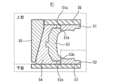
- FIG. 5 is a cross-sectional view showing a conventional tire mold
- FIG. 6 is a plan view showing a fully closed state of the tire mold, both showing a state after assembly.
- the tire mold 41 includes a pair of upper and lower side plates 51 and 52, a sector 53, a sector shoe 54 that holds the sector 53, and an actuator 55. Are arranged sequentially toward the direction.
- Reference numeral 57 denotes a lower mold plate that supports the lower side plate 52
- reference numeral 56 denotes an upper mold plate that supports the upper side plate 51.
- the sector 53, the sector shoe 54, the actuator 55, the upper side plate 51 and the upper mold plate 56 constitute an upper mold
- the lower side plate 52 and the lower mold plate 57 constitute a lower mold
- the position of the sector 53 with respect to the pair of upper and lower side plates 51 and 52 is such that the protruding portions 53a and 53b formed on the upper and lower sides of the sector 53 are the respective side plates 51 and 52. It is regulated by contacting the outer diameter portions 51a and 52a. As the actuator 55 moves up and down, the sector 53 attached to the sector shoe 54 slides inward and outward in the tire radial direction.
- the movement range of the sector shoe 54 is restricted with respect to the actuator 55.
- the sector shoe 54 is provided with a certain play (backlash) in the tire circumferential direction and the tire radial direction.
- the sector 53 is restricted from entering in the radial direction by contacting the side plates 51 and 52, but when assembled at room temperature, the inner diameter of the sector 53 is larger than the outer diameter of the side plates 51 and 52. Therefore, the accuracy of regulating the position of the sector 53 with respect to the side plates 51 and 52 is lowered in combination with the play in the circumferential direction.
- the assembly step of the conventional tire mold 41 even if the upper die core is slightly displaced from the lower die, the clearance S between the sectors 53 is unevenly distributed and the upper die is inclined with respect to the lower die. Thus, the tire mold 41 can be assembled.
- pressurization at the time of pressing is received by contacting the sector made of aluminum and the side plate in the tire radial direction and the side surfaces of the sector in the tire circumferential direction. With the use, the inner peripheral surface and sides of the sector were worn out, and it was necessary to cope with this.
- Patent Document 1 discloses a technique for preventing the wear of the sector by bringing the side surfaces of the sector shoe into contact with each other. By eliminating the clearance in the tire radial direction of the sector shoe, it is expected that the effect of suppressing the displacement of the upper and lower molds will be expected. However, since the allowance of the sector shoe in the tire radial direction is constant, a phenomenon occurs in which the sector cannot be closed depending on the mold.
- Patent Document 2 discloses a technique for suppressing the displacement of the upper and lower molds by devising the shape of the bottom surface of the sector shoe and the upper surface of the lower mold container in contact therewith, but it cannot prevent the sector from being worn out.
- an object of the present invention is to provide a tire mold that does not cause misalignment of the upper and lower molds and can prevent the sector from being worn.
- a tire mold in which a pair of upper and lower side plates, a sector, a sector shoe that holds the sector, and an actuator are sequentially arranged from the inner side to the outer side in the tire radial direction,
- a hook-shaped ring is provided on each outer diameter portion of the pair of upper and lower side plates, The shape of the bowl-shaped ring is When the mold is in a fully closed state at room temperature, the protrusions formed above and below the sector shoe come into contact with the outer diameter portion of the bowl-shaped ring, and the sector shoe and the sector are positioned with respect to the pair of upper and lower side plates.
- the inner diameter portion of the sector comes into contact with the outer diameter portion of the side plate, and the protrusions formed on the upper and lower sides of the sector shoe are outside the saddle-shaped ring.
- the tire mold is formed so as to be in contact with a diameter portion.
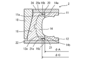
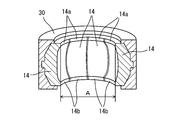
- FIGS. 2 and 3 are a cross-sectional view and a plan view showing a fully closed state of the tire mold of the present embodiment.
- the tire mold 2 is a split mold type mold installed in a press device, and is provided with saddle-shaped rings 20 and 21 to be described later on outer diameter portions 11a and 12a of a pair of upper and lower side plates 11 and 12, respectively. Except for this, it has the same configuration as a conventional tire mold.
- the tire mold 2 includes a pair of upper and lower side plates 11, 12, a plurality of sectors 14, a plurality of sector shoes 16 to which each sector 14 is attached, and an actuator 18 attached to each sector shoe 16;
- An upper mold plate 24 and a lower mold plate 22 that support the side plates 11 and 12 are provided.
- Each sector 14 is incorporated in the inner peripheral surface 16 a of the plurality of sector shoes 16.
- the plurality of sector shoes 16 are equally divided in the circumferential direction of the tire T in the same number as the sectors 14 and are annularly arranged.
- One sector 14 is held by one sector shoe 16.
- Reference numerals 14 c and 14 d denote side surfaces of the sector 14.
- the ring is fixed to the outer diameter portions 11a and 12a of the pair of upper and lower side plates 11 and 12 by welding or the like, and the upper portion and the outer diameter portion of the outer diameter portion 11a.
- An upper hook-shaped ring 20 and a lower hook-shaped ring 21 are formed at the lower part of 12a.
- the tire mold 2 is roughly divided into an upper mold and a lower mold, and the upper mold includes a sector 14, a sector shoe 16, an actuator 18, an upper side plate 11, an upper collar ring 20, and an upper mold plate 24.
- the lower mold includes a lower side plate 12, a lower collar ring 21, and a lower mold plate 22 (see FIG. 1).
- an aluminum alloy or aluminum that is lightweight and easy to cast and construct is selected for the sector 14, and the side plates 11 and 12 and the bowl-shaped rings 20 and 21 have a vulcanization temperature higher than that of aluminum.
- the iron having a small thermal expansion is selected, and the sector shoe 16 is selected to be iron.
- bowl-shaped rings 20 and 21 are formed as follows.
- the protrusions 16 b and 16 c formed on the upper and lower sides of the sector shoe 16 are the outer diameters of the bowl-shaped rings 20 and 21.
- the sector shoe 16 with respect to the side plates 11 and 12 and the sector 14 attached to the sector shoe 16 are positioned in contact with the portions 20a and 21a.
- the inner diameter portions (projections 14a and 14b) of the sector 14 come into contact with the outer diameter portions 11a and 11b of the side plates 11 and 12, and the sector Protrusions 16a and 16b formed on the upper and lower sides of the shoe 16 are formed so as to be in contact with outer diameter portions 20a and 21a of the bowl-shaped ring.
- the inner diameter of the projecting portions 14a and 14b) of the sector 14 in a state where the tire mold 2 is fully closed is A
- the outer diameter of the pair of upper and lower side plates 11 and 12 is B
- the sector shoe 16 projects when fully closed.
- the outer diameter D of the upper hook-shaped ring 20 or the lower hook-shaped ring 21 is formed so as to satisfy the following expression, where C is the inner diameter of the portion 16b and the protruding portion 16c. -0.5 ⁇ (CD)-(AB) ⁇ 0
- the iron ring having a smaller thermal expansion at the vulcanization temperature than aluminum is selected as the bowl-shaped ring, It is possible to design the dimensions of the ring relative to the dimensions of the sector shoe that are positioned in contact.
- the tire mold of the present embodiment is provided with the hook-shaped ring formed as described above, the conventional tire mold does not have such a hook-shaped ring. Compared to the above, it is possible to regulate the occurrence of concentric misalignment of the upper and lower molds with higher accuracy.
- the above-described tire mold including a sector having an inner diameter of A (mm), a side plate having an outer diameter of B (mm), and a sector shoe having an inner diameter of C (mm) is used.
- Various evaluations were performed by changing the outer diameter D (mm) of the bowl-shaped ring made of SS material (rolled steel for general structure).
- the inner diameter A of the inner peripheral surface of the sector described above is an inner diameter measured after the sector is assembled to the reference jig 30 as shown in FIG.
Landscapes
- Engineering & Computer Science (AREA)
- Mechanical Engineering (AREA)
- Moulds For Moulding Plastics Or The Like (AREA)
- Heating, Cooling, Or Curing Plastics Or The Like In General (AREA)
Priority Applications (3)
| Application Number | Priority Date | Filing Date | Title |
|---|---|---|---|
| US14/369,051 US9056436B2 (en) | 2012-01-16 | 2012-11-28 | Tire mold |
| CN201280065614.7A CN104023930B (zh) | 2012-01-16 | 2012-11-28 | 轮胎用模具 |
| EP12866128.7A EP2796264B1 (en) | 2012-01-16 | 2012-11-28 | Tire mold |
Applications Claiming Priority (2)
| Application Number | Priority Date | Filing Date | Title |
|---|---|---|---|
| JP2012-006373 | 2012-01-16 | ||
| JP2012006373A JP5631904B2 (ja) | 2012-01-16 | 2012-01-16 | タイヤ用モールド |
Publications (1)
| Publication Number | Publication Date |
|---|---|
| WO2013108490A1 true WO2013108490A1 (ja) | 2013-07-25 |
Family
ID=48798927
Family Applications (1)
| Application Number | Title | Priority Date | Filing Date |
|---|---|---|---|
| PCT/JP2012/080685 WO2013108490A1 (ja) | 2012-01-16 | 2012-11-28 | タイヤ用モールド |
Country Status (5)
| Country | Link |
|---|---|
| US (1) | US9056436B2 (zh) |
| EP (1) | EP2796264B1 (zh) |
| JP (1) | JP5631904B2 (zh) |
| CN (1) | CN104023930B (zh) |
| WO (1) | WO2013108490A1 (zh) |
Cited By (1)
| Publication number | Priority date | Publication date | Assignee | Title |
|---|---|---|---|---|
| CN107199658A (zh) * | 2017-06-29 | 2017-09-26 | 湖州宏侨橡胶机械有限公司 | 硫化机的模板座 |
Families Citing this family (15)
| Publication number | Priority date | Publication date | Assignee | Title |
|---|---|---|---|---|
| EP3013569B1 (en) * | 2013-06-28 | 2018-04-11 | Compagnie Générale des Etablissements Michelin | Tire mold with improved durability |
| JP6174994B2 (ja) * | 2013-12-27 | 2017-08-02 | 東洋ゴム工業株式会社 | タイヤ成型金型用測定治具及びその使用方法 |
| JP6235915B2 (ja) * | 2014-01-21 | 2017-11-22 | 住友ゴム工業株式会社 | タイヤ加硫用金型 |
| JP6434801B2 (ja) * | 2014-12-18 | 2018-12-05 | 住友ゴム工業株式会社 | タイヤ加硫用金型 |
| JP6498519B2 (ja) * | 2015-05-14 | 2019-04-10 | 住友ゴム工業株式会社 | コンテナモールド |
| ITUA20161676A1 (it) * | 2016-03-15 | 2017-09-15 | Sacmi | Metodo ed attrezzo per assemblare uno stampo femmina, e disposizione di stampo femmina. |
| WO2018029726A1 (ja) * | 2016-08-12 | 2018-02-15 | 東洋ゴム工業株式会社 | タイヤ加硫装置 |
| CN109689323B (zh) * | 2016-08-12 | 2021-07-13 | 通伊欧轮胎株式会社 | 轮胎硫化模具、轮胎硫化装置以及轮胎的制造方法 |
| JP6605737B2 (ja) * | 2016-08-12 | 2019-11-13 | Toyo Tire株式会社 | タイヤ加硫装置及びタイヤの製造方法 |
| WO2018029731A1 (ja) * | 2016-08-12 | 2018-02-15 | 東洋ゴム工業株式会社 | タイヤ加硫金型、タイヤ加硫装置及びタイヤの製造方法 |
| JP7094696B2 (ja) * | 2017-12-15 | 2022-07-04 | Toyo Tire株式会社 | トレッドモールド |
| JP7009985B2 (ja) | 2017-12-27 | 2022-02-10 | 住友ゴム工業株式会社 | タイヤ用モールド |
| CN108099236B (zh) * | 2018-01-10 | 2020-07-17 | 山东豪迈机械科技股份有限公司 | 一种轮胎模具侧板及轮胎模具 |
| IT201900005944A1 (it) * | 2019-04-17 | 2020-10-17 | Bridgestone Europe Nv Sa | Pneumatico reversibile provvisto di un doppio battistrada e corrispondenti impianto e metodo di produzione |
| CN110103495B (zh) * | 2019-05-06 | 2021-10-19 | 中车青岛四方车辆研究所有限公司 | 实心车轮硫化模具 |
Citations (8)
| Publication number | Priority date | Publication date | Assignee | Title |
|---|---|---|---|---|
| JPS4847970A (zh) * | 1971-10-15 | 1973-07-07 | ||
| JP2001009837A (ja) * | 1999-07-01 | 2001-01-16 | Mitsubishi Heavy Ind Ltd | タイヤ加硫用の割金型装置 |
| JP2003039435A (ja) * | 2001-07-31 | 2003-02-13 | Bridgestone Corp | タイヤ加硫金型 |
| JP2005059510A (ja) * | 2003-08-19 | 2005-03-10 | Sumitomo Rubber Ind Ltd | タイヤの成形型 |
| JP2008114603A (ja) * | 2006-11-02 | 2008-05-22 | Soc De Technol Michelin | タイヤを加硫する金型、生のタイヤブランクを加硫する方法及びこの方法により得られたタイヤ |
| JP2008194946A (ja) * | 2007-02-13 | 2008-08-28 | Toyo Tire & Rubber Co Ltd | タイヤ加硫成形金型及びタイヤ製造方法 |
| JP2010076344A (ja) | 2008-09-29 | 2010-04-08 | Sumitomo Rubber Ind Ltd | タイヤ用モールド |
| JP2011046069A (ja) | 2009-08-26 | 2011-03-10 | Sumitomo Rubber Ind Ltd | タイヤ加硫装置 |
Family Cites Families (6)
| Publication number | Priority date | Publication date | Assignee | Title |
|---|---|---|---|---|
| US3910735A (en) | 1971-10-15 | 1975-10-07 | Pirelli | Apparatus for molding and curing a pneumatic tire in a perfectly centered position with respect to the equatorial plane of the curing mold |
| FR2781411A1 (fr) * | 1998-07-23 | 2000-01-28 | Michelin Soc Tech | Moule pour pneumatique de vehicule, et presse de vulcanisation adaptee pour recevoir un tel moule |
| US6955782B1 (en) * | 1999-11-24 | 2005-10-18 | The Goodyear Tire & Rubber Company | Method of molding a tire and mold therefor |
| JP4236413B2 (ja) * | 2002-02-15 | 2009-03-11 | 株式会社ブリヂストン | タイヤ加硫装置 |
| JP4702130B2 (ja) * | 2006-03-22 | 2011-06-15 | 横浜ゴム株式会社 | タイヤ成形用二分割金型 |
| JP4971887B2 (ja) * | 2007-06-28 | 2012-07-11 | 東洋ゴム工業株式会社 | タイヤ加硫用コンテナ |
-
2012
- 2012-01-16 JP JP2012006373A patent/JP5631904B2/ja not_active Expired - Fee Related
- 2012-11-28 CN CN201280065614.7A patent/CN104023930B/zh not_active Expired - Fee Related
- 2012-11-28 WO PCT/JP2012/080685 patent/WO2013108490A1/ja active Application Filing
- 2012-11-28 US US14/369,051 patent/US9056436B2/en not_active Expired - Fee Related
- 2012-11-28 EP EP12866128.7A patent/EP2796264B1/en not_active Not-in-force
Patent Citations (8)
| Publication number | Priority date | Publication date | Assignee | Title |
|---|---|---|---|---|
| JPS4847970A (zh) * | 1971-10-15 | 1973-07-07 | ||
| JP2001009837A (ja) * | 1999-07-01 | 2001-01-16 | Mitsubishi Heavy Ind Ltd | タイヤ加硫用の割金型装置 |
| JP2003039435A (ja) * | 2001-07-31 | 2003-02-13 | Bridgestone Corp | タイヤ加硫金型 |
| JP2005059510A (ja) * | 2003-08-19 | 2005-03-10 | Sumitomo Rubber Ind Ltd | タイヤの成形型 |
| JP2008114603A (ja) * | 2006-11-02 | 2008-05-22 | Soc De Technol Michelin | タイヤを加硫する金型、生のタイヤブランクを加硫する方法及びこの方法により得られたタイヤ |
| JP2008194946A (ja) * | 2007-02-13 | 2008-08-28 | Toyo Tire & Rubber Co Ltd | タイヤ加硫成形金型及びタイヤ製造方法 |
| JP2010076344A (ja) | 2008-09-29 | 2010-04-08 | Sumitomo Rubber Ind Ltd | タイヤ用モールド |
| JP2011046069A (ja) | 2009-08-26 | 2011-03-10 | Sumitomo Rubber Ind Ltd | タイヤ加硫装置 |
Cited By (1)
| Publication number | Priority date | Publication date | Assignee | Title |
|---|---|---|---|---|
| CN107199658A (zh) * | 2017-06-29 | 2017-09-26 | 湖州宏侨橡胶机械有限公司 | 硫化机的模板座 |
Also Published As
| Publication number | Publication date |
|---|---|
| CN104023930B (zh) | 2016-04-13 |
| JP5631904B2 (ja) | 2014-11-26 |
| US9056436B2 (en) | 2015-06-16 |
| US20140377392A1 (en) | 2014-12-25 |
| EP2796264A1 (en) | 2014-10-29 |
| CN104023930A (zh) | 2014-09-03 |
| JP2013144414A (ja) | 2013-07-25 |
| EP2796264A4 (en) | 2016-05-11 |
| EP2796264B1 (en) | 2018-10-10 |
Similar Documents
| Publication | Publication Date | Title |
|---|---|---|
| WO2013108490A1 (ja) | タイヤ用モールド | |
| JP4972425B2 (ja) | タイヤ加硫成形金型及びタイヤ製造方法 | |
| JP2015227062A (ja) | タイヤ加硫モールドのためのスキンを含む内張り組立体 | |
| JP5008708B2 (ja) | タイヤ用モールド | |
| JP2014008745A (ja) | タイヤ成形ドラム | |
| JP4709883B2 (ja) | タイヤ用モールド | |
| JP2008023722A (ja) | タイヤ用モールド | |
| JP5254198B2 (ja) | タイヤ用モールド | |
| US9731462B2 (en) | Mold and method for vulcanizing tires | |
| JP5175772B2 (ja) | タイヤ成形金型 | |
| JP2016047556A (ja) | 車輪支持用転がり軸受ユニット | |
| WO2017168886A1 (ja) | タイヤ加硫金型装置 | |
| JP2014065151A (ja) | ビードリング | |
| WO2018061054A1 (ja) | タイヤ加硫金型 | |
| JP3718492B2 (ja) | ホイールの製造方法及び製造装置 | |
| JPWO2018029729A1 (ja) | タイヤ加硫金型、タイヤ加硫装置及びタイヤの製造方法 | |
| JP2020082511A (ja) | タイヤ加硫用金型 | |
| JP7468222B2 (ja) | モールド | |
| JP2016043490A (ja) | タイヤ用コンテナモールド | |
| JP6641799B2 (ja) | タイヤ金型 | |
| JP6130762B2 (ja) | タイヤ成型用金型及びタイヤ成型方法 | |
| JP2013132666A (ja) | 段付円柱状部材の製造方法及び車輪支持用転がり軸受ユニット | |
| JP3237977U (ja) | タイヤ加硫金型装置 | |
| JP2008179046A (ja) | タイヤ加硫用金型 | |
| WO2019224969A1 (ja) | タイヤ加硫金型装置 |
Legal Events
| Date | Code | Title | Description |
|---|---|---|---|
| 121 | Ep: the epo has been informed by wipo that ep was designated in this application |
Ref document number: 12866128 Country of ref document: EP Kind code of ref document: A1 |
|
| WWE | Wipo information: entry into national phase |
Ref document number: 14369051 Country of ref document: US |
|
| WWE | Wipo information: entry into national phase |
Ref document number: IDP00201404408 Country of ref document: ID |
|
| WWE | Wipo information: entry into national phase |
Ref document number: 2012866128 Country of ref document: EP |
|
| NENP | Non-entry into the national phase |
Ref country code: DE |