WO2013108490A1 - タイヤ用モールド - Google Patents
タイヤ用モールド Download PDFInfo
- Publication number
- WO2013108490A1 WO2013108490A1 PCT/JP2012/080685 JP2012080685W WO2013108490A1 WO 2013108490 A1 WO2013108490 A1 WO 2013108490A1 JP 2012080685 W JP2012080685 W JP 2012080685W WO 2013108490 A1 WO2013108490 A1 WO 2013108490A1
- Authority
- WO
- WIPO (PCT)
- Prior art keywords
- sector
- mold
- tire
- shoe
- side plates
- Prior art date
Links
Images


Classifications
-
- B—PERFORMING OPERATIONS; TRANSPORTING
- B29—WORKING OF PLASTICS; WORKING OF SUBSTANCES IN A PLASTIC STATE IN GENERAL
- B29D—PRODUCING PARTICULAR ARTICLES FROM PLASTICS OR FROM SUBSTANCES IN A PLASTIC STATE
- B29D30/00—Producing pneumatic or solid tyres or parts thereof
- B29D30/06—Pneumatic tyres or parts thereof (e.g. produced by casting, moulding, compression moulding, injection moulding, centrifugal casting)
- B29D30/0601—Vulcanising tyres; Vulcanising presses for tyres
- B29D30/0606—Vulcanising moulds not integral with vulcanising presses
- B29D30/0629—Vulcanising moulds not integral with vulcanising presses with radially movable sectors
- B29D2030/0631—Means for forcing adjacent mould sectors away one from another, e.g. using springs or the like, to create repulsive forces
-
- B—PERFORMING OPERATIONS; TRANSPORTING
- B29—WORKING OF PLASTICS; WORKING OF SUBSTANCES IN A PLASTIC STATE IN GENERAL
- B29K—INDEXING SCHEME ASSOCIATED WITH SUBCLASSES B29B, B29C OR B29D, RELATING TO MOULDING MATERIALS OR TO MATERIALS FOR MOULDS, REINFORCEMENTS, FILLERS OR PREFORMED PARTS, e.g. INSERTS
- B29K2905/00—Use of metals, their alloys or their compounds, as mould material
- B29K2905/02—Aluminium
-
- B—PERFORMING OPERATIONS; TRANSPORTING
- B29—WORKING OF PLASTICS; WORKING OF SUBSTANCES IN A PLASTIC STATE IN GENERAL
- B29K—INDEXING SCHEME ASSOCIATED WITH SUBCLASSES B29B, B29C OR B29D, RELATING TO MOULDING MATERIALS OR TO MATERIALS FOR MOULDS, REINFORCEMENTS, FILLERS OR PREFORMED PARTS, e.g. INSERTS
- B29K2905/00—Use of metals, their alloys or their compounds, as mould material
- B29K2905/08—Transition metals
- B29K2905/12—Iron
Definitions
- the present invention relates to a tire mold composed of a split mold.
- a tire mold composed of a split mold is generally used, and after being assembled at room temperature, it is attached to a vulcanizer (press).
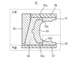
- FIG. 5 is a cross-sectional view showing a conventional tire mold
- FIG. 6 is a plan view showing a fully closed state of the tire mold, both showing a state after assembly.
- the tire mold 41 includes a pair of upper and lower side plates 51 and 52, a sector 53, a sector shoe 54 that holds the sector 53, and an actuator 55. Are arranged sequentially toward the direction.
- Reference numeral 57 denotes a lower mold plate that supports the lower side plate 52
- reference numeral 56 denotes an upper mold plate that supports the upper side plate 51.
- the sector 53, the sector shoe 54, the actuator 55, the upper side plate 51 and the upper mold plate 56 constitute an upper mold
- the lower side plate 52 and the lower mold plate 57 constitute a lower mold
- the position of the sector 53 with respect to the pair of upper and lower side plates 51 and 52 is such that the protruding portions 53a and 53b formed on the upper and lower sides of the sector 53 are the respective side plates 51 and 52. It is regulated by contacting the outer diameter portions 51a and 52a. As the actuator 55 moves up and down, the sector 53 attached to the sector shoe 54 slides inward and outward in the tire radial direction.
- the movement range of the sector shoe 54 is restricted with respect to the actuator 55.
- the sector shoe 54 is provided with a certain play (backlash) in the tire circumferential direction and the tire radial direction.
- the sector 53 is restricted from entering in the radial direction by contacting the side plates 51 and 52, but when assembled at room temperature, the inner diameter of the sector 53 is larger than the outer diameter of the side plates 51 and 52. Therefore, the accuracy of regulating the position of the sector 53 with respect to the side plates 51 and 52 is lowered in combination with the play in the circumferential direction.
- the assembly step of the conventional tire mold 41 even if the upper die core is slightly displaced from the lower die, the clearance S between the sectors 53 is unevenly distributed and the upper die is inclined with respect to the lower die. Thus, the tire mold 41 can be assembled.
- pressurization at the time of pressing is received by contacting the sector made of aluminum and the side plate in the tire radial direction and the side surfaces of the sector in the tire circumferential direction. With the use, the inner peripheral surface and sides of the sector were worn out, and it was necessary to cope with this.
- Patent Document 1 discloses a technique for preventing the wear of the sector by bringing the side surfaces of the sector shoe into contact with each other. By eliminating the clearance in the tire radial direction of the sector shoe, it is expected that the effect of suppressing the displacement of the upper and lower molds will be expected. However, since the allowance of the sector shoe in the tire radial direction is constant, a phenomenon occurs in which the sector cannot be closed depending on the mold.
- Patent Document 2 discloses a technique for suppressing the displacement of the upper and lower molds by devising the shape of the bottom surface of the sector shoe and the upper surface of the lower mold container in contact therewith, but it cannot prevent the sector from being worn out.
- an object of the present invention is to provide a tire mold that does not cause misalignment of the upper and lower molds and can prevent the sector from being worn.
- a tire mold in which a pair of upper and lower side plates, a sector, a sector shoe that holds the sector, and an actuator are sequentially arranged from the inner side to the outer side in the tire radial direction,
- a hook-shaped ring is provided on each outer diameter portion of the pair of upper and lower side plates, The shape of the bowl-shaped ring is When the mold is in a fully closed state at room temperature, the protrusions formed above and below the sector shoe come into contact with the outer diameter portion of the bowl-shaped ring, and the sector shoe and the sector are positioned with respect to the pair of upper and lower side plates.
- the inner diameter portion of the sector comes into contact with the outer diameter portion of the side plate, and the protrusions formed on the upper and lower sides of the sector shoe are outside the saddle-shaped ring.
- the tire mold is formed so as to be in contact with a diameter portion.
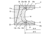
- FIGS. 2 and 3 are a cross-sectional view and a plan view showing a fully closed state of the tire mold of the present embodiment.
- the tire mold 2 is a split mold type mold installed in a press device, and is provided with saddle-shaped rings 20 and 21 to be described later on outer diameter portions 11a and 12a of a pair of upper and lower side plates 11 and 12, respectively. Except for this, it has the same configuration as a conventional tire mold.
- the tire mold 2 includes a pair of upper and lower side plates 11, 12, a plurality of sectors 14, a plurality of sector shoes 16 to which each sector 14 is attached, and an actuator 18 attached to each sector shoe 16;
- An upper mold plate 24 and a lower mold plate 22 that support the side plates 11 and 12 are provided.
- Each sector 14 is incorporated in the inner peripheral surface 16 a of the plurality of sector shoes 16.
- the plurality of sector shoes 16 are equally divided in the circumferential direction of the tire T in the same number as the sectors 14 and are annularly arranged.
- One sector 14 is held by one sector shoe 16.
- Reference numerals 14 c and 14 d denote side surfaces of the sector 14.
- the ring is fixed to the outer diameter portions 11a and 12a of the pair of upper and lower side plates 11 and 12 by welding or the like, and the upper portion and the outer diameter portion of the outer diameter portion 11a.
- An upper hook-shaped ring 20 and a lower hook-shaped ring 21 are formed at the lower part of 12a.
- the tire mold 2 is roughly divided into an upper mold and a lower mold, and the upper mold includes a sector 14, a sector shoe 16, an actuator 18, an upper side plate 11, an upper collar ring 20, and an upper mold plate 24.
- the lower mold includes a lower side plate 12, a lower collar ring 21, and a lower mold plate 22 (see FIG. 1).
- an aluminum alloy or aluminum that is lightweight and easy to cast and construct is selected for the sector 14, and the side plates 11 and 12 and the bowl-shaped rings 20 and 21 have a vulcanization temperature higher than that of aluminum.
- the iron having a small thermal expansion is selected, and the sector shoe 16 is selected to be iron.
- bowl-shaped rings 20 and 21 are formed as follows.
- the protrusions 16 b and 16 c formed on the upper and lower sides of the sector shoe 16 are the outer diameters of the bowl-shaped rings 20 and 21.
- the sector shoe 16 with respect to the side plates 11 and 12 and the sector 14 attached to the sector shoe 16 are positioned in contact with the portions 20a and 21a.
- the inner diameter portions (projections 14a and 14b) of the sector 14 come into contact with the outer diameter portions 11a and 11b of the side plates 11 and 12, and the sector Protrusions 16a and 16b formed on the upper and lower sides of the shoe 16 are formed so as to be in contact with outer diameter portions 20a and 21a of the bowl-shaped ring.
- the inner diameter of the projecting portions 14a and 14b) of the sector 14 in a state where the tire mold 2 is fully closed is A
- the outer diameter of the pair of upper and lower side plates 11 and 12 is B
- the sector shoe 16 projects when fully closed.
- the outer diameter D of the upper hook-shaped ring 20 or the lower hook-shaped ring 21 is formed so as to satisfy the following expression, where C is the inner diameter of the portion 16b and the protruding portion 16c. -0.5 ⁇ (CD)-(AB) ⁇ 0
- the iron ring having a smaller thermal expansion at the vulcanization temperature than aluminum is selected as the bowl-shaped ring, It is possible to design the dimensions of the ring relative to the dimensions of the sector shoe that are positioned in contact.
- the tire mold of the present embodiment is provided with the hook-shaped ring formed as described above, the conventional tire mold does not have such a hook-shaped ring. Compared to the above, it is possible to regulate the occurrence of concentric misalignment of the upper and lower molds with higher accuracy.
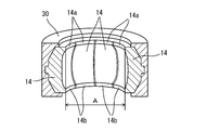
- the above-described tire mold including a sector having an inner diameter of A (mm), a side plate having an outer diameter of B (mm), and a sector shoe having an inner diameter of C (mm) is used.
- Various evaluations were performed by changing the outer diameter D (mm) of the bowl-shaped ring made of SS material (rolled steel for general structure).
- the inner diameter A of the inner peripheral surface of the sector described above is an inner diameter measured after the sector is assembled to the reference jig 30 as shown in FIG.
Landscapes
- Engineering & Computer Science (AREA)
- Mechanical Engineering (AREA)
- Moulds For Moulding Plastics Or The Like (AREA)
- Heating, Cooling, Or Curing Plastics Or The Like In General (AREA)
Abstract
上下一対のサイドプレートと、セクターと、セクターを保持するセクターシューと、アクチュエーターとが、タイヤ半径方向の内方から外方に向けて順次配置されたタイヤ用モールドであって、上下一対のサイドプレートのそれぞれの外径部に鍔状リングが設けられており、鍔状リングが、モールドが全閉状態で常温のときには、セクターシューの上下に形成された突出部が鍔状リングの外径部に接触して、上下一対のサイドプレートに対するセクターシューおよびセクターの位置決めを行うと共に、モールドが全閉状態で加硫温度に達したときには、セクターの内径部がサイドプレートの外径部に接触すると共に、セクターシューの上下に形成された突出部が鍔状リングの外径部に接触するように形成されていることを特徴とし、上下型の芯ずれを発生させることがなく、またセクターの摩滅を防止することができるタイヤ用モールドを提供する。
Description
本発明は、割りモールドから構成されるタイヤ用モールドに関するものである。
空気入りタイヤの製造に際しては、一般に、割りモールドから構成されるタイヤ用モールドが使用され、常温で組付けられた後、加硫機(プレス)に取付けられる。
図5は、従来のタイヤ用モールドを示す断面図、図6は、タイヤ用モールドの全閉状態を示す平面図であり、いずれも組付け後の状態を示している。
図5に示すように、タイヤ用モールド41は、上下一対のサイドプレート51、52と、セクター53と、セクター53を保持するセクターシュー54と、アクチュエーター55とを、タイヤ半径方向の内方から外方に向けて順次配置して構成されている。そして、57は下サイドプレート52を支持する下型プレートであり、56は上サイドプレート51を支持する上型プレートである。
また、図5において、セクター53、セクターシュー54、アクチュエーター55、上サイドプレート51および上型プレート56により上型が構成され、下サイドプレート52および下型プレート57により下型が構成される。
組付けられたタイヤ用モールド41の全閉時、上下一対のサイドプレート51、52に対するセクター53の位置は、セクター53の上下に形成された突出部53a、53bがサイドプレート51、52のそれぞれの外径部51a、52aに接触することにより規制される。そして、アクチュエーター55が昇降することにより、セクターシュー54に取付けられたセクター53がタイヤ半径方向の内方および外方に摺動する。
このように、セクターシュー54は、アクチュエーター55に対して移動範囲が規制されているが、セクターシュー54のタイヤ径方向への摺動を円滑にするために、図6に示すように、各々のセクターシュー54には、タイヤ周方向およびタイヤ半径方向に一定の遊び(ガタ)が設けられている。
また、前記したように、タイヤ用モールド41の組付けは常温で行われるため、アルミニウム製のセクター53の各々には、加硫温度による熱膨張を考慮して、タイヤ周方向にクリアランスSが形成されている。
このため、タイヤ用モールド41の組付け段階においては、セクターシュー54およびセクターシュー54に取付けられたセクター53の周方向の位置は規制されない。
そして、セクター53はサイドプレート51、52に接触することにより、径方向への入り込み代が規制されるが、常温での組付け時には、セクター53の内径はサイドプレート51、52の外径よりも大きいため、上記した周方向の遊びとも相俟って、サイドプレート51、52に対してセクター53の位置を規制する精度が低くなる。この結果、従来のタイヤ用モールド41の組付け段階においては、下型に対する上型の芯が少しずれていても、セクター53間のクリアランスSが偏在し、下型に対して上型が傾くことにより、タイヤ用モールド41を組付けることができる。
そこで、従来は、タイヤ用モールド41の組付けに際して、セクターシュー54およびセクター53の遊びやセクター53同士のクリアランスSに治具(図示省略)を挿入して組付けを行っていた。
しかし、このような挿入治具を用いた場合、作業負荷が大きくなる。
また、従来のモールドにおいては、プレス時の加圧を、アルミニウム製のセクターとサイドプレートがタイヤ径方向で接触すると共に、セクターの側面同士がタイヤ周方向で接触することで受けていたため、モールドの使用に伴いセクターの内周面や側面が摩滅し、これに対応する必要があった。
このような問題に対して、特許文献1には、セクターシューの側面同士を接触させることにより、セクターの摩滅を防ぐ技術が開示されている。セクターシューのタイヤ半径方向のクリアランスをなくすことにより、上下型のずれを抑制する効果が見込まれる。しかし、セクターシューのタイヤ半径方向への入り込み代が一定になるため、モールドによってはセクターが閉まりきらない現象が発生する。
また、特許文献2は、セクターシューの底面およびこれと接する下型コンテナ上面の形状を工夫して上下型のずれを抑制する技術が開示されているが、セクターの摩滅を防ぐことはできない。
そこで、本発明は、上記に鑑み、上下型の芯ずれを発生させることがなく、またセクターの摩滅を防止することができるタイヤ用モールドを提供することを課題とする。
請求項1に記載の発明は、
上下一対のサイドプレートと、セクターと、セクターを保持するセクターシューと、アクチュエーターとが、タイヤ半径方向の内方から外方に向けて順次配置されたタイヤ用モールドであって、
上下一対の前記サイドプレートのそれぞれの外径部に鍔状リングが設けられており、
前記鍔状リングの形状が、
モールドが全閉状態で常温のときには、前記セクターシューの上下に形成された突出部が前記鍔状リングの外径部に接触して、上下一対の前記サイドプレートに対する前記セクターシューおよび前記セクターの位置決めを行うと共に、
モールドが全閉状態で加硫温度に達したときには、前記セクターの内径部が前記サイドプレートの外径部に接触すると共に、前記セクターシューの上下に形成された突出部が前記鍔状リングの外径部に接触する
ように形成されている
ことを特徴とするタイヤ用モールドである。
本発明によれば、上下型の芯ずれを発生させることがなく、またセクターの摩滅を防止することができるタイヤ用モールドを提供することができる。
以下、実施の形態に基づき、図面を参照しつつ本発明を説明する。
1.タイヤ用モールドの全体構成
図1は本実施の形態のタイヤ用モールドを示す断面図、図2および図3は本実施の形態のタイヤ用モールドの全閉状態を示す断面図および平面図である。
図1は本実施の形態のタイヤ用モールドを示す断面図、図2および図3は本実施の形態のタイヤ用モールドの全閉状態を示す断面図および平面図である。
タイヤ用モールド2は、プレス装置に設置される割りモールド形式のモールドであって、上下一対のサイドプレート11、12のそれぞれの外径部11a、12aに後記する鍔状リング20、21が設けられている以外は、従来のタイヤ用モールドと同様の構成となっている。
即ち、タイヤ用モールド2は、上下一対のサイドプレート11、12と、複数のセクター14と、各セクター14が取り付けられた複数のセクターシュー16と、各セクターシュー16に取り付けられたアクチュエーター18と、各サイドプレート11、12を支持する上型プレート24および下型プレート22とを備えている。
複数のセクターシュー16の内周面16aには、各セクター14が組込まれている。複数のセクターシュー16は、セクター14と同数に、タイヤTの周方向に均等に分割され、かつ、環状に配置されている。1つのセクター14は、1つのセクターシュー16によって保持されている。なお、14c、14dはセクター14の側面である。
そして、本実施の形態におけるタイヤ用モールド2は、上下一対のサイドプレート11、12のそれぞれの外径部11a、12aにリングが溶接などで固定されて、外径部11aの上部および外径部12aの下部にそれぞれ上鍔状リング20および下鍔状リング21が形成されている。
なお、タイヤ用モールド2は、上型と下型に大きく分けられ、上型はセクター14、セクターシュー16、アクチュエーター18、上サイドプレート11、上鍔状リング20および上型プレート24を備えており、下型は下サイドプレート12、下鍔状リング21および下型プレート22を備えている(図1参照)。
タイヤ用モールドの材料としては、セクター14は、軽量で、鋳造および施工が容易であるアルミニウム合金またはアルミニウムが選択され、サイドプレート11、12および鍔状リング20、21は、アルミニウムよりも加硫温度での熱膨張が小さい鉄が選択され、セクターシュー16は、鉄が選択される。
2.鍔状リングの説明
鍔状リング20、21は、以下のように形成されている。
鍔状リング20、21は、以下のように形成されている。
即ち、タイヤ用モールド2を常温(約25℃)下で組付けて全閉した場合には、セクターシュー16の上下に形成された突出部16b、16cが、鍔状リング20、21の外径部20a、21aに接触して、サイドプレート11、12に対するセクターシュー16、およびセクターシュー16に取付けられたセクター14の位置決めを行うように形成されている。
また、タイヤ用モールド2が全閉状態で加硫温度に達したときには、セクター14の内径部(突出部14a、14b)がサイドプレート11、12の外径部11a、11bに接触すると共に、セクターシュー16の上下に形成された突出部16a、16bが鍔状リングの外径部20a,21aに接触するように形成されている。
そして、タイヤ用モールド2が全閉された状態におけるセクター14の突出部14a、14b)の内径をA、上下一対のサイドプレート11、12の外径をB、全閉時のセクターシュー16の突出部16b、突出部16cの内径をCとしたとき、上鍔状リング20もしくは下鍔状リング21の外径Dが以下の式を満足するように形成されていることが好ましい。
-0.5<(C-D)-(A-B)<0
-0.5<(C-D)-(A-B)<0
また、前記したように、本実施の形態のタイヤ用モールドにおいては、鍔状リングとして、アルミニウムよりも加硫温度での熱膨張が小さい鉄製のリングを選択しているため、常温組付け時から、接触して位置決めが行われるセクターシューの寸法に対して、リングの寸法を設計することが可能となる。
3.本実施の形態の効果
(1)本実施の形態のタイヤ用モールドは、上記のように形成された鍔状リングが設けられているため、このような鍔状リングを有しない従来のタイヤ用モールドに比べて、より高い精度で上下型の同芯ずれの発生を規制することができる。
(1)本実施の形態のタイヤ用モールドは、上記のように形成された鍔状リングが設けられているため、このような鍔状リングを有しない従来のタイヤ用モールドに比べて、より高い精度で上下型の同芯ずれの発生を規制することができる。
そして、このように上下型の同芯ずれの発生が高い精度で規制されて組付けられたタイヤ用モールドは、その精度を保ったままでプレスに取付けられるため、上下型の同芯ずれにより生じるタイヤ外観不良の発生を充分に抑制することができる。
(2)また、上下型の同芯ずれの状態でモールドへの加圧を続けることによりセクターの内周面および側面の偏摩滅を発生する従来のタイヤ用モールドと異なり、セクターの内周面および側面の偏摩滅を抑制することができるため、タイヤ外観不良の発生をさらに抑制することができると共に、モールド耐用寿命の延長を図ることができる。
(3)さらに、上下型の同芯ずれやそれによるクリアランス、セクターのタイヤ周方向での偏在がなくなるため、タイヤユニフォミティの向上を図ることができる。
(4)さらに、プレスの加圧力を、鉄製の鍔状リングとサイドプレートとが接触して受けることができるため、使用に伴い発生するセクターの摩滅および真円精度低下を抑制することができる。
以下においては、内周面の内径がA(mm)のセクター、外径がB(mm)サイドプレート、内周面の内径がC(mm)のセクターシューを備えた上記のタイヤ用モールドを用いて、SS材(一般構造用圧延鋼材)製の鍔状リングの外径D(mm)を変化させて、種々の評価を行った。
なお、上記したセクターの内周面の内径Aは、図4に示すように、基準治具30にセクターを組付けた後に測定した内径である。
1.実験
表1の各々に示す「(C-D)-(A-B)」となるように、鍔状リングの外径Dが設定された各タイヤ用モールドを製作し、200日間使用した。
表1の各々に示す「(C-D)-(A-B)」となるように、鍔状リングの外径Dが設定された各タイヤ用モールドを製作し、200日間使用した。
2.評価方法
200日間使用後、セクター内径の摩滅量(mm)、およびセクターの真円度変化(mm)を測定すると共に、製品タイヤにおける外観不良の発生の有無を確認し、「OK」、「NG」で総合判定を行った。結果を表1に示す。
200日間使用後、セクター内径の摩滅量(mm)、およびセクターの真円度変化(mm)を測定すると共に、製品タイヤにおける外観不良の発生の有無を確認し、「OK」、「NG」で総合判定を行った。結果を表1に示す。

3.評価
表1に示す通り、比較例1、2の場合、外観不良が発生し、セクター内径摩滅量およびセクター真円度変化が許容範囲を超えて大きいため、「NG」と判定された。また、比較例3の場合、外観不良は発生しなかったものの、セクター内径摩滅量およびセクター真円度変化が許容範囲を超えて大きいため、「NG」と判定された。これは、リングの外径が小さすぎたために、プレスの加圧力によりセクターが摩滅し、セクター真円度を変化させたものと考えられる。
表1に示す通り、比較例1、2の場合、外観不良が発生し、セクター内径摩滅量およびセクター真円度変化が許容範囲を超えて大きいため、「NG」と判定された。また、比較例3の場合、外観不良は発生しなかったものの、セクター内径摩滅量およびセクター真円度変化が許容範囲を超えて大きいため、「NG」と判定された。これは、リングの外径が小さすぎたために、プレスの加圧力によりセクターが摩滅し、セクター真円度を変化させたものと考えられる。
そして、比較例4~6の場合、セクター内径摩滅量およびセクター真円度変化はないものの、外観不良が発生したため、「NG」と判定された。これは、リングの外径が大きすぎるため、プレス時、サイドプレートとセクターとの間に隙間が生じたものと考えられる。
これに対して、実施例1~3の場合、外観不良が発生せず、セクター内径摩滅量およびセクター真円度変化が許容範囲であったため、「OK」と判定された。これは、リングの外径が適切に設定されたことによる。特に、実施例3の場合には、外観不良が発生せず、セクター内径摩滅量およびセクター真円度変化も認められず、特に好ましい結果が得られた。
以上のことから、適切な形状に形成された鍔状リングが設けられたタイヤ用モールドの場合、外観不良、セクター内径摩滅、セクター真円度変化が発生しないことが分かる。
以上、本発明を実施の形態に基づいて説明したが、本発明は上記の実施の形態に限定されるものではない。本発明と同一および均等の範囲内において、上記の実施の形態に対して種々の変更を加えることができる。
2、41 タイヤ用モールド
11、51 上サイドプレート
11a、51a 上サイドプレートの外径部
12、52 下サイドプレート
12a、52a 下サイドプレートの外径部
14、53 セクター
14a、14b、53a、53b セクターの突出部
14c セクターの側面
14d セクターの側面
16、54 セクターシュー
16a セクターシューの内周面
16b、16c セクターシューの突出部
18、55 アクチュエーター
20 上鍔状リング
20a 上鍔状リングの外径部
21 下鍔状リング
21a 下鍔状リングの外径部
22、57 下型プレート
24、56 上型プレート
A セクターの突出部の全閉時の内径
B サイドプレートの外径
C セクターシューの突出部の全閉時の内径
D 鍔状リングの外径
S クリアランス
Claims (1)
- 上下一対のサイドプレートと、セクターと、セクターを保持するセクターシューと、アクチュエーターとが、タイヤ半径方向の内方から外方に向けて順次配置されたタイヤ用モールドであって、
上下一対の前記サイドプレートのそれぞれの外径部に鍔状リングが設けられており、
前記鍔状リングが、
モールドが全閉状態で常温のときには、前記セクターシューの上下に形成された突出部が前記鍔状リングの外径部に接触して、上下一対の前記サイドプレートに対する前記セクターシューおよび前記セクターの位置決めを行うと共に、
モールドが全閉状態で加硫温度に達したときには、前記セクターの内径部が前記サイドプレートの外径部に接触すると共に、前記セクターシューの上下に形成された突出部が前記鍔状リングの外径部に接触する
ように形成されていることを特徴とするタイヤ用モールド。
Priority Applications (3)
| Application Number | Priority Date | Filing Date | Title |
|---|---|---|---|
| US14/369,051 US9056436B2 (en) | 2012-01-16 | 2012-11-28 | Tire mold |
| CN201280065614.7A CN104023930B (zh) | 2012-01-16 | 2012-11-28 | 轮胎用模具 |
| EP12866128.7A EP2796264B1 (en) | 2012-01-16 | 2012-11-28 | Tire mold |
Applications Claiming Priority (2)
| Application Number | Priority Date | Filing Date | Title |
|---|---|---|---|
| JP2012-006373 | 2012-01-16 | ||
| JP2012006373A JP5631904B2 (ja) | 2012-01-16 | 2012-01-16 | タイヤ用モールド |
Publications (1)
| Publication Number | Publication Date |
|---|---|
| WO2013108490A1 true WO2013108490A1 (ja) | 2013-07-25 |
Family
ID=48798927
Family Applications (1)
| Application Number | Title | Priority Date | Filing Date |
|---|---|---|---|
| PCT/JP2012/080685 WO2013108490A1 (ja) | 2012-01-16 | 2012-11-28 | タイヤ用モールド |
Country Status (5)
| Country | Link |
|---|---|
| US (1) | US9056436B2 (ja) |
| EP (1) | EP2796264B1 (ja) |
| JP (1) | JP5631904B2 (ja) |
| CN (1) | CN104023930B (ja) |
| WO (1) | WO2013108490A1 (ja) |
Cited By (1)
| Publication number | Priority date | Publication date | Assignee | Title |
|---|---|---|---|---|
| CN107199658A (zh) * | 2017-06-29 | 2017-09-26 | 湖州宏侨橡胶机械有限公司 | 硫化机的模板座 |
Families Citing this family (15)
| Publication number | Priority date | Publication date | Assignee | Title |
|---|---|---|---|---|
| EP3013569B1 (en) * | 2013-06-28 | 2018-04-11 | Compagnie Générale des Etablissements Michelin | Tire mold with improved durability |
| JP6174994B2 (ja) * | 2013-12-27 | 2017-08-02 | 東洋ゴム工業株式会社 | タイヤ成型金型用測定治具及びその使用方法 |
| JP6235915B2 (ja) * | 2014-01-21 | 2017-11-22 | 住友ゴム工業株式会社 | タイヤ加硫用金型 |
| JP6434801B2 (ja) * | 2014-12-18 | 2018-12-05 | 住友ゴム工業株式会社 | タイヤ加硫用金型 |
| JP6498519B2 (ja) * | 2015-05-14 | 2019-04-10 | 住友ゴム工業株式会社 | コンテナモールド |
| ITUA20161676A1 (it) * | 2016-03-15 | 2017-09-15 | Sacmi | Metodo ed attrezzo per assemblare uno stampo femmina, e disposizione di stampo femmina. |
| WO2018029726A1 (ja) * | 2016-08-12 | 2018-02-15 | 東洋ゴム工業株式会社 | タイヤ加硫装置 |
| CN109689323B (zh) * | 2016-08-12 | 2021-07-13 | 通伊欧轮胎株式会社 | 轮胎硫化模具、轮胎硫化装置以及轮胎的制造方法 |
| JP6605737B2 (ja) * | 2016-08-12 | 2019-11-13 | Toyo Tire株式会社 | タイヤ加硫装置及びタイヤの製造方法 |
| WO2018029731A1 (ja) * | 2016-08-12 | 2018-02-15 | 東洋ゴム工業株式会社 | タイヤ加硫金型、タイヤ加硫装置及びタイヤの製造方法 |
| JP7094696B2 (ja) * | 2017-12-15 | 2022-07-04 | Toyo Tire株式会社 | トレッドモールド |
| JP7009985B2 (ja) | 2017-12-27 | 2022-02-10 | 住友ゴム工業株式会社 | タイヤ用モールド |
| CN108099236B (zh) * | 2018-01-10 | 2020-07-17 | 山东豪迈机械科技股份有限公司 | 一种轮胎模具侧板及轮胎模具 |
| IT201900005944A1 (it) * | 2019-04-17 | 2020-10-17 | Bridgestone Europe Nv Sa | Pneumatico reversibile provvisto di un doppio battistrada e corrispondenti impianto e metodo di produzione |
| CN110103495B (zh) * | 2019-05-06 | 2021-10-19 | 中车青岛四方车辆研究所有限公司 | 实心车轮硫化模具 |
Citations (8)
| Publication number | Priority date | Publication date | Assignee | Title |
|---|---|---|---|---|
| JPS4847970A (ja) * | 1971-10-15 | 1973-07-07 | ||
| JP2001009837A (ja) * | 1999-07-01 | 2001-01-16 | Mitsubishi Heavy Ind Ltd | タイヤ加硫用の割金型装置 |
| JP2003039435A (ja) * | 2001-07-31 | 2003-02-13 | Bridgestone Corp | タイヤ加硫金型 |
| JP2005059510A (ja) * | 2003-08-19 | 2005-03-10 | Sumitomo Rubber Ind Ltd | タイヤの成形型 |
| JP2008114603A (ja) * | 2006-11-02 | 2008-05-22 | Soc De Technol Michelin | タイヤを加硫する金型、生のタイヤブランクを加硫する方法及びこの方法により得られたタイヤ |
| JP2008194946A (ja) * | 2007-02-13 | 2008-08-28 | Toyo Tire & Rubber Co Ltd | タイヤ加硫成形金型及びタイヤ製造方法 |
| JP2010076344A (ja) | 2008-09-29 | 2010-04-08 | Sumitomo Rubber Ind Ltd | タイヤ用モールド |
| JP2011046069A (ja) | 2009-08-26 | 2011-03-10 | Sumitomo Rubber Ind Ltd | タイヤ加硫装置 |
Family Cites Families (6)
| Publication number | Priority date | Publication date | Assignee | Title |
|---|---|---|---|---|
| US3910735A (en) | 1971-10-15 | 1975-10-07 | Pirelli | Apparatus for molding and curing a pneumatic tire in a perfectly centered position with respect to the equatorial plane of the curing mold |
| FR2781411A1 (fr) * | 1998-07-23 | 2000-01-28 | Michelin Soc Tech | Moule pour pneumatique de vehicule, et presse de vulcanisation adaptee pour recevoir un tel moule |
| US6955782B1 (en) * | 1999-11-24 | 2005-10-18 | The Goodyear Tire & Rubber Company | Method of molding a tire and mold therefor |
| JP4236413B2 (ja) * | 2002-02-15 | 2009-03-11 | 株式会社ブリヂストン | タイヤ加硫装置 |
| JP4702130B2 (ja) * | 2006-03-22 | 2011-06-15 | 横浜ゴム株式会社 | タイヤ成形用二分割金型 |
| JP4971887B2 (ja) * | 2007-06-28 | 2012-07-11 | 東洋ゴム工業株式会社 | タイヤ加硫用コンテナ |
-
2012
- 2012-01-16 JP JP2012006373A patent/JP5631904B2/ja not_active Expired - Fee Related
- 2012-11-28 CN CN201280065614.7A patent/CN104023930B/zh not_active Expired - Fee Related
- 2012-11-28 WO PCT/JP2012/080685 patent/WO2013108490A1/ja active Application Filing
- 2012-11-28 US US14/369,051 patent/US9056436B2/en not_active Expired - Fee Related
- 2012-11-28 EP EP12866128.7A patent/EP2796264B1/en not_active Not-in-force
Patent Citations (8)
| Publication number | Priority date | Publication date | Assignee | Title |
|---|---|---|---|---|
| JPS4847970A (ja) * | 1971-10-15 | 1973-07-07 | ||
| JP2001009837A (ja) * | 1999-07-01 | 2001-01-16 | Mitsubishi Heavy Ind Ltd | タイヤ加硫用の割金型装置 |
| JP2003039435A (ja) * | 2001-07-31 | 2003-02-13 | Bridgestone Corp | タイヤ加硫金型 |
| JP2005059510A (ja) * | 2003-08-19 | 2005-03-10 | Sumitomo Rubber Ind Ltd | タイヤの成形型 |
| JP2008114603A (ja) * | 2006-11-02 | 2008-05-22 | Soc De Technol Michelin | タイヤを加硫する金型、生のタイヤブランクを加硫する方法及びこの方法により得られたタイヤ |
| JP2008194946A (ja) * | 2007-02-13 | 2008-08-28 | Toyo Tire & Rubber Co Ltd | タイヤ加硫成形金型及びタイヤ製造方法 |
| JP2010076344A (ja) | 2008-09-29 | 2010-04-08 | Sumitomo Rubber Ind Ltd | タイヤ用モールド |
| JP2011046069A (ja) | 2009-08-26 | 2011-03-10 | Sumitomo Rubber Ind Ltd | タイヤ加硫装置 |
Cited By (1)
| Publication number | Priority date | Publication date | Assignee | Title |
|---|---|---|---|---|
| CN107199658A (zh) * | 2017-06-29 | 2017-09-26 | 湖州宏侨橡胶机械有限公司 | 硫化机的模板座 |
Also Published As
| Publication number | Publication date |
|---|---|
| CN104023930B (zh) | 2016-04-13 |
| JP5631904B2 (ja) | 2014-11-26 |
| US9056436B2 (en) | 2015-06-16 |
| US20140377392A1 (en) | 2014-12-25 |
| EP2796264A1 (en) | 2014-10-29 |
| CN104023930A (zh) | 2014-09-03 |
| JP2013144414A (ja) | 2013-07-25 |
| EP2796264A4 (en) | 2016-05-11 |
| EP2796264B1 (en) | 2018-10-10 |
Similar Documents
| Publication | Publication Date | Title |
|---|---|---|
| WO2013108490A1 (ja) | タイヤ用モールド | |
| JP4972425B2 (ja) | タイヤ加硫成形金型及びタイヤ製造方法 | |
| JP2015227062A (ja) | タイヤ加硫モールドのためのスキンを含む内張り組立体 | |
| JP5008708B2 (ja) | タイヤ用モールド | |
| JP2014008745A (ja) | タイヤ成形ドラム | |
| JP4709883B2 (ja) | タイヤ用モールド | |
| JP2008023722A (ja) | タイヤ用モールド | |
| JP5254198B2 (ja) | タイヤ用モールド | |
| US9731462B2 (en) | Mold and method for vulcanizing tires | |
| JP5175772B2 (ja) | タイヤ成形金型 | |
| JP2016047556A (ja) | 車輪支持用転がり軸受ユニット | |
| WO2017168886A1 (ja) | タイヤ加硫金型装置 | |
| JP2014065151A (ja) | ビードリング | |
| WO2018061054A1 (ja) | タイヤ加硫金型 | |
| JP3718492B2 (ja) | ホイールの製造方法及び製造装置 | |
| JPWO2018029729A1 (ja) | タイヤ加硫金型、タイヤ加硫装置及びタイヤの製造方法 | |
| JP2020082511A (ja) | タイヤ加硫用金型 | |
| JP7468222B2 (ja) | モールド | |
| JP2016043490A (ja) | タイヤ用コンテナモールド | |
| JP6641799B2 (ja) | タイヤ金型 | |
| JP6130762B2 (ja) | タイヤ成型用金型及びタイヤ成型方法 | |
| JP2013132666A (ja) | 段付円柱状部材の製造方法及び車輪支持用転がり軸受ユニット | |
| JP3237977U (ja) | タイヤ加硫金型装置 | |
| JP2008179046A (ja) | タイヤ加硫用金型 | |
| WO2019224969A1 (ja) | タイヤ加硫金型装置 |
Legal Events
| Date | Code | Title | Description |
|---|---|---|---|
| 121 | Ep: the epo has been informed by wipo that ep was designated in this application |
Ref document number: 12866128 Country of ref document: EP Kind code of ref document: A1 |
|
| WWE | Wipo information: entry into national phase |
Ref document number: 14369051 Country of ref document: US |
|
| WWE | Wipo information: entry into national phase |
Ref document number: IDP00201404408 Country of ref document: ID |
|
| WWE | Wipo information: entry into national phase |
Ref document number: 2012866128 Country of ref document: EP |
|
| NENP | Non-entry into the national phase |
Ref country code: DE |