WO2013084796A1 - Dispositif d'épissurage - Google Patents
Dispositif d'épissurage Download PDFInfo
- Publication number
- WO2013084796A1 WO2013084796A1 PCT/JP2012/080974 JP2012080974W WO2013084796A1 WO 2013084796 A1 WO2013084796 A1 WO 2013084796A1 JP 2012080974 W JP2012080974 W JP 2012080974W WO 2013084796 A1 WO2013084796 A1 WO 2013084796A1
- Authority
- WO
- WIPO (PCT)
- Prior art keywords
- tape
- pressing member
- movable
- open position
- fixed
- Prior art date
Links
Images


Classifications
-
- B—PERFORMING OPERATIONS; TRANSPORTING
- B65—CONVEYING; PACKING; STORING; HANDLING THIN OR FILAMENTARY MATERIAL
- B65H—HANDLING THIN OR FILAMENTARY MATERIAL, e.g. SHEETS, WEBS, CABLES
- B65H21/00—Apparatus for splicing webs
-
- H—ELECTRICITY
- H05—ELECTRIC TECHNIQUES NOT OTHERWISE PROVIDED FOR
- H05K—PRINTED CIRCUITS; CASINGS OR CONSTRUCTIONAL DETAILS OF ELECTRIC APPARATUS; MANUFACTURE OF ASSEMBLAGES OF ELECTRICAL COMPONENTS
- H05K13/00—Apparatus or processes specially adapted for manufacturing or adjusting assemblages of electric components
- H05K13/02—Feeding of components
- H05K13/0215—Interconnecting of containers, e.g. splicing of tapes
-
- B—PERFORMING OPERATIONS; TRANSPORTING
- B65—CONVEYING; PACKING; STORING; HANDLING THIN OR FILAMENTARY MATERIAL
- B65H—HANDLING THIN OR FILAMENTARY MATERIAL, e.g. SHEETS, WEBS, CABLES
- B65H2301/00—Handling processes for sheets or webs
- B65H2301/40—Type of handling process
- B65H2301/46—Splicing
- B65H2301/462—Form of splice
- B65H2301/4622—Abutting article or web portions, i.e. edge to edge
- B65H2301/46222—Abutting article or web portions, i.e. edge to edge involving double butt splice, i.e. adhesive tape applied on both sides of the article or web portions
-
- B—PERFORMING OPERATIONS; TRANSPORTING
- B65—CONVEYING; PACKING; STORING; HANDLING THIN OR FILAMENTARY MATERIAL
- B65H—HANDLING THIN OR FILAMENTARY MATERIAL, e.g. SHEETS, WEBS, CABLES
- B65H2301/00—Handling processes for sheets or webs
- B65H2301/40—Type of handling process
- B65H2301/46—Splicing
- B65H2301/463—Splicing splicing means, i.e. means by which a web end is bound to another web end
- B65H2301/4631—Adhesive tape
-
- B—PERFORMING OPERATIONS; TRANSPORTING
- B65—CONVEYING; PACKING; STORING; HANDLING THIN OR FILAMENTARY MATERIAL
- B65H—HANDLING THIN OR FILAMENTARY MATERIAL, e.g. SHEETS, WEBS, CABLES
- B65H2301/00—Handling processes for sheets or webs
- B65H2301/40—Type of handling process
- B65H2301/46—Splicing
- B65H2301/464—Splicing effecting splice
- B65H2301/4641—Splicing effecting splice by pivoting element
-
- B—PERFORMING OPERATIONS; TRANSPORTING
- B65—CONVEYING; PACKING; STORING; HANDLING THIN OR FILAMENTARY MATERIAL
- B65H—HANDLING THIN OR FILAMENTARY MATERIAL, e.g. SHEETS, WEBS, CABLES
- B65H2404/00—Parts for transporting or guiding the handled material
- B65H2404/70—Other elements in edge contact with handled material, e.g. registering, orientating, guiding devices
- B65H2404/72—Stops, gauge pins, e.g. stationary
-
- B—PERFORMING OPERATIONS; TRANSPORTING
- B65—CONVEYING; PACKING; STORING; HANDLING THIN OR FILAMENTARY MATERIAL
- B65H—HANDLING THIN OR FILAMENTARY MATERIAL, e.g. SHEETS, WEBS, CABLES
- B65H2701/00—Handled material; Storage means
- B65H2701/10—Handled articles or webs
- B65H2701/19—Specific article or web
- B65H2701/1942—Web supporting regularly spaced non-adhesive articles
Definitions
- the present invention relates to a splicing device used when, for example, a new tape is added to an old tape in a tape feeder that supplies electronic components to an electronic component mounting machine.
- the tape feeder is mounted on the electronic component mounting machine. Tape is wound around the tape feeder. A large number of electronic components are accommodated in the tape at predetermined intervals in the longitudinal direction. As electronic components are mounted on the substrate from the tape, the number of electronic components on the tape gradually decreases. A new tape having an electronic component of the same component type is connected to an old tape in which the remaining amount of the electronic component is equal to or less than a predetermined amount. This connection work is called splicing work.
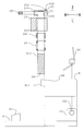
- FIG. 11 (a) shows a schematic diagram of the first stage of the splicing work of the tape.
- FIG. 11B shows a schematic diagram of the second stage of the tape splicing operation.
- FIG. 11C shows a schematic diagram of the third stage of the tape splicing operation.
- the operator cuts the vicinity of the front end 105c of the new tape 105 with a scissors 106 at a predetermined cutting position 105d. Similarly, the operator cuts the vicinity of the rear end 102c of the tape 102 in use with the scissors 106 at a predetermined cutting position 102d.
- the operator aligns the cutting position 105d of the new tape 105 with the cutting position 102d of the tape 102 in use.
- the operator connects the new tape 105 and the tape 102 in use by the splice tape 107. In this way, the splicing operation is executed.
- the splicing work is performed manually by the operator, it is complicated. Also, the operator may touch the adhesive surface of the splice tape 107 during work. For this reason, sweat, dirt, etc. may adhere and the adhesive force of the splice tape 107 may be weakened. In addition, the splicing accuracy depends on the skill level of the operator's skill.
- Patent Document 1 discloses a splicing device that performs splicing work without depending on the manual work of the operator.
- a pair of old and new tapes are set on a pair of tape holding bases.
- the pair of tape holding bases are reversed.
- the splice tape is attached to the upward surface (front surface) of the pair of old and new tapes.
- the pair of tape holding bases are reversed again.
- a splice tape is affixed on the upward surface (back surface) of a pair of new and old tapes. In this way, the splicing operation is performed.
- the splicing work can be easily executed.
- the operator is less likely to touch the adhesive surface of the splice tape 107 during work.
- the splicing accuracy is unlikely to depend on the skill level of the operator's skill.
- the splicing device described in the same document it is necessary to rotate a pair of tape holding bases, that is, a pair of old and new tapes, a plurality of times with respect to the stationary splicing tape during the splicing operation. For this reason, there is a possibility that the pair of old and new tapes may be displaced from each other. That is, the splicing accuracy may be reduced. In this case, the new tape may be bent and connected to the old tape like a broken line. In addition, at the joint between the old and new tapes, the pitch of the tape feed holes may be out of order.
- the splicing device of the present invention has been completed in view of the above problems.
- An object of the present invention is to provide a splicing device in which splicing accuracy is unlikely to decrease.
- the splicing device of the present invention can be switched between a fixed pressing member, an open position opened with respect to the fixed pressing member, and a closed position closed with respect to the fixed pressing member.
- a splicing tape disposed between the movable pressing member and the fixed pressing member at the open position.
- the first connecting end portion of the first tape and the second connecting end portion of the second tape are arranged, and the movable pressing member is switched from the open position to the closed position. Is closed with respect to the fixed pressing member, the movable pressing member overlaps the fixed pressing member in the front and back direction, and the splice stay is between the movable pressing member and the fixed pressing member. Is folded, the first connecting end and the second connecting end are sandwiched by the splice tape from the front and back directions, and the first connecting end and the second connecting end are connected.
- a splice tape is arranged so as to straddle the movable pressing member and the fixed pressing member. And the 1st connection end part of a 1st tape and the 2nd connection end part of a 2nd tape are arrange
- the surface of the splice tape is an adhesive surface. However, at this time, the back surface of the first connection end portion and the back surface of the second connection end portion may or may not be bonded to the bonding surface.
- the movable pressing member When moving from the open position to the closed position, the movable pressing member is closed with respect to the fixed pressing member. For this reason, the movable pressing member overlaps with the fixed pressing member in the front and back direction. At this time, the splice tape is folded between the movable pressing member and the fixed pressing member. Moreover, a 1st connection end part and a 2nd connection end part are clamped with the splice tape from the front and back direction. By being sandwiched, the surface of the first connecting end and the surface of the second connecting end are bonded to the back surface of the splice tape. In addition, the back surface of the first connection end and the back surface of the second connection end are bonded to the surface of the splice tape.
- the first connection end, and the second connection end, the first connection end and the second connection end are formed by the splice tape. Adheres firmly from the front and back. In this way, the first connecting end of the first tape and the second connecting end of the second tape are connected via the splice tape.
- the originally complicated splicing work can be easily executed. Further, the operator may touch the adhesive surface of the splice tape only when the splice tape, the first tape, and the second tape are set in the open position. For this reason, there is little possibility that an operator touches the adhesive surface of the splice tape. Therefore, there is little possibility that the adhesive force of the splice tape becomes weak. Also, the splicing accuracy is unlikely to depend on the skill level of the operator's skill.
- the splicing device of the present invention it is the splice tape that moves when the first tape, the second tape, and the splice tape are switched from the open position to the closed position. That is, the first connecting end of the first tape and the second connecting end of the second tape are both immobile. For this reason, in the splicing operation, the first connecting end and the second connecting end are unlikely to be displaced from each other. That is, the splicing accuracy is unlikely to decrease.
- the angle between the fixed pressing member and the movable pressing member at the open position is approximately 180 °. According to this configuration, the splice tape can be set without being bent in the open position.
- an operation unit that is operated by human power and supplies the movable pressing member with a driving force when switching from the open position to the closed position is provided.
- the splicing operation can be executed by the operator manually moving the operation unit. For this reason, even when there is no supply of electricity, the splicing operation can be executed with high accuracy.
- the movable pressing member when the actual moving amount of the movable pressing member has not reached the predetermined moving amount that can connect the first connecting end and the second connecting end, the movable pressing member does not return. In other words, the movable pressing member does not return unless the connection between the first connection end and the second connection end is completed. For this reason, splicing work can be executed reliably.
- the first connecting end and the second connecting end are connected by the splice tape in the closed position of the tape connecting portion.
- the first connecting end portion and the second connecting end portion are positioned with respect to the splice tape.
- the positioning portion can accurately and easily position the splice tape, the first connection end, and the second connection end.
- the splice tape includes a first hole row including a plurality of first positioning holes arranged in a longitudinal direction of the splice tape, and a short direction of the first hole row.
- a plurality of second hole rows arranged in parallel with each other in the longitudinal direction of the splice tape, and the first tape has a plurality of first feed holes arranged in the longitudinal direction of the first tape.
- the second tape has a plurality of second feed holes arranged in the longitudinal direction of the second tape, and the positioning portion is disposed in the fixed pressing member, and in the open position, from the back side A first positioning hole, a fixed positioning pin to be inserted into the first feeding hole and the second feeding hole, and the movable pressing member; and at the open position, the first positioning hole is inserted into the second positioning hole from the back side; Switch from the open position to the closed position When, better to adopt a configuration having a movable positioning pin inserted from the front side to the said first feed holes and said second feeding hole.
- the fixed positioning pin of the positioning part is inserted into the first positioning hole, the first feeding hole, and the second feeding hole from the back side, so that the splice tape and the first connecting end are located with respect to the positioning part.
- the part and the second connecting end are fixed.
- the splicing tape is fixed to the positioning portion by inserting the movable positioning pin of the positioning portion into the second positioning hole from the back side.
- the movable positioning pin When switching from the open position to the closed position, the movable positioning pin is inserted into the first feed hole and the second feed hole from the front side in addition to the already inserted second positioning hole. For this reason, a splice tape, a 1st connection end part, and a 2nd connection end part are positioned with respect to a positioning part from the front and back direction. In this state, the first connecting end and the second connecting end are connected by the splice tape. According to this configuration, the splicing tape, the first connecting end, and the second connecting end can be accurately and easily positioned by the positioning portion.
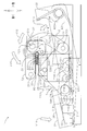
- FIG. 1 is a perspective view of a splicing device as an embodiment of the splicing device of the present invention.
- FIG. 2 is an exploded perspective view of the splicing device.
- FIG. 3 is a transparent right side view of the splicing device.
- FIG. 4 is an exploded transparent right side view of the splicing device.
- FIG. 5 is an exploded view of the lower part of FIG. 6 is an exploded view of the middle part of FIG.
- FIG. 7 is an exploded view of the upper part of FIG.
- FIG. 8 is a perspective view of the splicing device at the open position of the fixed pressing member and the movable pressing member.
- FIG. 9 is a transparent side view in the middle of switching from the open position to the closed position of the splicing device.
- FIG. 10 is a transparent right side view of the splicing device in a closed position.
- FIG. 11A is a schematic diagram of the first stage of the splicing work of the tape.
- FIG. 11B is a schematic diagram of the second stage of the tape splicing operation.
- FIG. 11C is a schematic diagram of a third stage of the tape splicing operation.
- FIG. 1 shows a perspective view of the splicing device of the present embodiment.
- FIG. 2 shows an exploded perspective view of the splicing device.
- FIG. 3 shows a transparent right side view of the splicing device.
- FIG. 4 shows an exploded transparent right side view of the splicing device.
- FIG. 5 shows an exploded view of the lower part of FIG.
- FIG. 6 shows an exploded view of the middle part of FIG.
- FIG. 7 shows an exploded view of the upper part of FIG.
- the splicing device 1 includes a tape connecting portion 2, an operation portion 3, a backward movement portion 32, a restriction portion 5, a base 6, and a link portion 7. .
- the base 6 includes a stopper 61 and a pair of brackets 62.
- the base 6 has a flat plate shape.
- the stopper 61 has a rectangular parallelepiped block shape.
- the stopper 61 is disposed on the upper surface of the front portion of the base 6.
- the stopper 61 sets a bottom dead center of the operation unit 3 described later.
- the pair of brackets 62 are disposed on the upper surface of the rear end portion of the base 6. From the left surface (outer surface) of the left bracket 62 and the right surface (outer surface) of the right bracket 62, swinging shafts 620 are projected.
- the operation unit 3 includes a pressing unit 30 and a pair of arms 31.
- Each of the pair of arms 31 has a thin plate shape extending in the front-rear direction.
- the pair of arms 31 are spaced apart in the left-right direction.
- the pressing part 30 has a flat plate shape.
- the pressing part 30 is constructed between the front ends of the pair of arms 31.
- a pressing force is input to the pressing unit 30 from the operator.
- a pair of swing shafts 620 are inserted into the rear ends of the pair of arms 31. Therefore, the operation unit 3 can swing around the swing shaft 620.
- Each of the pair of arms 31 includes a guide hole 310.
- Each of the pair of guide holes 310 has a long hole shape that is long in the front-rear direction.
- a rocking shaft 311 protrudes from the left surface of the right arm 31.
- the return movement part 32 is a so-called return spring.
- the return movement portion 32 is mounted on the swing shaft 620. One end of the return movement portion 32 is in elastic contact with the upper surface of the base 6. The other end of the return portion 32 is in elastic contact with the rear end of the arm 31.
- the backward movement portion 32 urges the operation portion 3 in a direction away from the base 6.
- the restriction unit 5 includes a restriction member 50, a pawl member 51, a bracket 52, and a spring 53.
- the regulating member 50 has a standing wall shape.
- the regulating member 50 is fixed to the right surface of the base 6 (shown by hatching in FIG. 2).
- the restricting member 50 is disposed between the base 6 and the right arm 31.
- a plurality of regulating teeth 500 are formed on the front edge of the regulating member 50.
- the bracket 52 is disposed on the left surface of the right arm 31.
- the pawl member 51 is inserted into the swing shaft 311.
- the pawl member 51 can swing around the swing shaft 311.
- an obtuse angle non-engaging portion 511 is disposed in the upper rear corner of the pawl member 51.
- a right-angle engaging portion 510 is disposed in the lower rear corner of the pawl member 51.
- the spring 53 is interposed between the bracket 52 and the front end of the pawl member 51. The spring 53 urges the pawl member 51 forward.
- the pawl member 51 can move only from above to below with respect to the restriction tooth 500.
- the pawl member 51 is movable from below to above with respect to the restriction tooth 500.
- the tape connecting portion 2 includes a fixed pressing member 20, a movable pressing member 21, a positioning portion 22, a fixing block 23, a pair of guide shafts 24, a pair of springs 25, a pair of retaining pins 26, and a pair.
- the support part 27 is provided.
- Each of the pair of guide shafts 24 has a round bar shape extending in the vertical direction.
- the guide shaft 24 protrudes from the upper surface of the base 6.
- the pair of guide shafts 24 are arranged in the left-right direction.
- a planar pressure contact surface 240 is disposed on each of the upper end front surfaces of the pair of guide shafts 24.
- the fixed block 23 has a rectangular parallelepiped shape.
- the fixed block 23 includes a pair of shaft insertion holes 230 and a pair of bushes 231.
- the pair of shaft insertion holes 230 penetrates the fixed block 23 in the vertical direction.
- the pair of shaft insertion holes 230 are arranged in the left-right direction.
- the guide shafts 24 are inserted through the pair of shaft insertion holes 230, respectively.
- Each of the pair of bushes 231 is fitted into an upper portion of the shaft insertion hole 230.
- Each of the pair of springs 25 is inserted into the shaft insertion hole 230.
- the lower ends of the pair of springs 25 are in elastic contact with the upper surface of the base 6.
- the upper ends of the pair of springs 25 are in elastic contact with the lower ends of the bushes 231, respectively.
- the pair of springs 25 urges the entire tape connecting portion 2 (excluding the pair of guide shafts 24) upward.
- the fixed pressing member 20 has a rectangular parallelepiped plate shape.
- the fixed pressing member 20 is disposed above the fixed block 23.
- the fixed pressing member 20 includes a pair of shaft housing recesses 200 and a pair of shaft retaining holes 201.
- the pair of shaft housing recesses 200 are recessed in the lower surface of the fixed pressing member 20.
- a pair of shaft accommodation recessed parts 200 are located in a line with the left-right direction.
- the upper ends of the pair of guide shafts 24 are housed in the pair of shaft housing recesses 200.
- the pair of shaft retaining holes 201 are formed in the front surface of the fixed pressing member 20.
- the rear ends of the pair of shaft retaining holes 201 communicate with the shaft accommodating recess 200, respectively.
- the pair of retaining pins 26 are screwed into the pair of shaft retaining holes 201.
- the rear ends of the pair of retaining pins 26 are in pressure contact with the pressure contact surfaces 240 of the guide shaft 24, respectively.
- the retaining pin 26 prevents the fixed pressing member 20 from coming out of the guide shaft 24 by the urging force of the spring 25.
- the fixed block 23 is movable in the vertical direction between the upper surface of the base 6 and the lower surface of the fixed pressing member 20. That is, the fixed block 23, a pair of support portions 27 to be described later, and a movable pressing member 21 to be described later are movable in the vertical direction while being urged by the spring 25. For this reason, when the movable pressing member 21 is switched from the open position to the closed position, the movable pressing member 21 can be pushed downward while resisting the biasing force of the spring 25.
- the movable pressing member 21 has a rectangular parallelepiped plate shape. As shown in FIG. 2, the movable pressing member 21 is juxtaposed behind the fixed pressing member 20 in the open position. The movable pressing member 21 is movable from the open position to a closed position that is inverted above the fixed pressing member 20 and juxtaposed in the vertical direction.
- the movable pressing member 21 includes a pair of drive connecting portions 210, a pair of guided portions 211, and a pair of tape support portions 212.
- the pair of drive connecting portions 210 are provided so as to protrude from both the left and right sides of the rear end of the movable pressing member 21.
- the pair of guided portions 211 are provided so as to protrude from both the left and right sides of the front end of the movable pressing member 21.
- the pair of tape support portions 212 protrude from the upper surface of the front end of the movable pressing member 21.
- each of the first tape and the second tape to be connected has a C-shaped winding hook that opens downward. In the open position, the first tape and the second tape get over the pair of tape support portions 212 by using this curl, and are set on the fixed pressing member 20.
- the members constituting the positioning portion 22 are divided into a fixed pressing member 20 and a movable pressing member 21.
- the positioning unit 22 includes a plurality of fixed positioning pins 220, a plurality of movable positioning pins 221, a plurality of fixed positioning holes 222, and a plurality of movable positioning holes 223.
- the plurality of fixed positioning pins 220 and the plurality of fixed positioning holes 222 are disposed in the rear portion of the fixed pressing member 20.
- the plurality of fixed positioning pins 220 and the plurality of fixed positioning holes 222 are arranged in a line in the left-right direction.
- the plurality of fixed positioning pins 220 and the plurality of fixed positioning holes 222 are alternately arranged.
- the plurality of movable positioning pins 221 and the plurality of movable positioning holes 223 are arranged in the front portion of the movable pressing member 21.
- the plurality of movable positioning pins 221 and the plurality of movable positioning holes 223 are arranged in a line in the left-right direction.
- the plurality of movable positioning pins 221 and the plurality of movable positioning holes 223 are alternately arranged.
- the movable positioning pin 221 and the fixed positioning hole 222 are opposed to each other in the front-rear direction.
- the fixed positioning pin 220 and the movable positioning hole 223 are opposed to each other in the front-rear direction.
- the movable positioning pin 221 can enter the fixed positioning hole 222 when switching from the open position to the closed position. Further, the fixed positioning pin 220 can enter the movable positioning hole 223.
- Each of the pair of support portions 27 has a standing wall shape.
- the pair of support portions 27 are fixed to the left and right walls of the fixed block 23 as shown by hatching in FIG.
- Each of the pair of support portions 27 includes a guide portion 270 and swing shafts 271 and 272.
- the pair of guide portions 270 are disposed on the right surface (inner surface) of the left support portion 27 and on the left surface (inner surface) of the right support portion 27.
- the guide part 270 has a C-shaped groove shape when viewed from the left or right side.
- a pair of guided portions 211 are accommodated in the pair of guide portions 270.
- the guided portion 211 is movable in the guide portion 270 along the shape of the guide portion 270.
- the pair of swing shafts 271 are disposed on the left surface (outer surface) of the left support portion 27 and the right surface (outer surface) of the right support portion 27.
- the pair of swing shafts 271 are respectively disposed in the upper front portion of the support portion 27.
- the pair of swing shafts 272 are disposed on the left surface (outer surface) of the left support portion 27 and the right surface (outer surface) of the right support portion 27.
- the pair of swing shafts 272 are respectively disposed in the upper center portion of the support portion 27.
- the link unit 7 includes a pair of first link members 70, a pair of second link members 71, and a pair of third link members 72.
- the pair of first link members 70, the pair of second link members 71, and the pair of third link members 72 are separately arranged on the outer sides in the left-right direction of the pair of support portions 27.
- the configuration and movement of the first link member 70, the second link member 71 and the third link member 72 on the left side are the configuration and movement of the first link member 70, the second link member 71 and the third link member 72 on the right side, It is the same.
- the arrangement of the first link member 70, the second link member 71, and the third link member 72 on the left side is symmetrical to the arrangement of the first link member 70, the second link member 71, and the third link member 72 on the right side. .
- the structure and movement of the right first link member 70, the second link member 71, and the third link member 72 will be described below as representative of these link members.
- the first link member 70 has a triangular plate shape when viewed from the left or right side.
- a swing shaft 271 is inserted from the left at the rear end of the first link member 70. Therefore, the first link member 70 can swing around the swing shaft 271.
- a guided projection 700 is fixed to the front end of the first link member 70 from the right side through a guide hole 310 of the arm 31.
- a connecting shaft 701 projects from the right surface of the lower end of the first link member 70.
- the second link member 71 has a C-shaped plate shape when viewed from the left or right side.
- a connecting shaft 701 is inserted into the C-shaped one end (front end) of the second link member 71 from the left. Therefore, the second link member 71 can swing with respect to the first link member 70.
- the third link member 72 is L-shaped when viewed from the left or right side.
- a swing shaft 272 is inserted into the L-shaped end (front end) of the third link member 72 from the left. For this reason, the third link member 72 can swing around the swing shaft 272.
- a connecting shaft 720 protrudes from the right surface of the L-shaped bent portion of the third link member 72.
- the connecting shaft 720 is inserted into the C-shaped other end (rear end) of the second link member 71.
- the third link member 72 can swing relative to the second link member 71.
- the drive connecting portion 210 is inserted into the L-shaped other end (rear end) of the third link member 72 from the left side. For this reason, the third link member 72 can swing with respect to the movable pressing member 21.
- FIG. 8 shows a perspective view of the splicing device of the present embodiment at the open position of the fixed pressing member and the movable pressing member.
- the splice tape 9 includes a protective film 90, a front surface adhesive tape 91, a back surface adhesive tape 92, a first hole array 93, and a second hole array 94.
- the protective film 90 has a rectangular thin film shape.
- the upper surface of the protective film 90 is an adhesive surface.
- the surface adhesive tape 91 has a strip shape extending in the left-right direction (longitudinal direction).
- the front surface adhesive tape 91 is disposed on the rear portion of the upper surface of the protective film 90 (upper surface portion of the movable pressing member 21).
- the upper surface of the front surface adhesive tape 91 is an adhesive surface.
- the back surface adhesive tape 92 has a strip shape extending in the left-right direction.
- the back surface adhesive tape 92 is disposed on the front portion of the upper surface of the protective film 90 (upper surface portion of the fixed pressing member 20).
- the upper surface of the back surface adhesive tape 92 is an adhesive surface.
- the first hole row 93 includes a total of eight first positioning holes 930.
- the first hole row 93 extends in the left-right direction.
- the first hole row 93 is disposed in the front portion of the upper surface of the protective film 90.
- the first positioning hole 930 passes through the vicinity of the rear edge of the back surface adhesive tape 92 and the protective film 90 in the vertical direction (front and back direction). Fixed positioning pins 220 are inserted into the eight first positioning holes 930 from every other side.
- the second hole row 94 includes a total of eight second positioning holes 940.
- the second hole row 94 extends in the left-right direction.
- the second hole row 94 is disposed in the rear portion of the upper surface of the protective film 90.
- the second positioning hole 940 penetrates the protective film 90 in the vertical direction. In the eight second positioning holes 940, movable positioning pins 221 are inserted from every other side.
- the first tape 80 includes a carrier tape 800, a pair of upper and lower cover tapes 801 (shown transparent in FIG. 8 for convenience of explanation), a large number of first feed holes 802, and a large number of component accommodating portions 803. It is equipped with.
- a number of first feed holes 802 are formed in the carrier tape 800.
- the multiple first feed holes 802 are arranged at a predetermined pitch along the left-right direction of the carrier tape 800.
- a large number of component housing portions 803 are formed in the carrier tape 800.
- a large number of component housing portions 803 are arranged at a predetermined pitch along the left-right direction of the carrier tape 800.
- a pair of front and back cover tapes 801 seals the upper and lower openings of the component housing portion 803.
- the component storage unit 803 can store electronic components (not shown).
- a first connection end 804 is disposed at the right end of the first tape 80.
- the configuration of the second tape 81 is the same as the configuration of the first tape 80. That is, the second tape 81 includes a carrier tape 810, a pair of upper and lower cover tapes 811, a large number of second feed holes 812, and a large number of component accommodating portions 813.
- a second connection end 814 is disposed at the left end of the second tape 81. The second connection end 814 and the first connection end 804 are in contact with each other in the left-right direction.
- FIG. 9 shows a transparent right side view of the splicing device in the closed position. 9 and 10 correspond to FIG.
- the operator sets the splice tape 9, the first tape 80, and the second tape 81 in the open position as shown in FIG. Specifically, first, the operator places the splice tape 9 on the upper surface of the fixed pressing member 20 and the upper surface of the movable pressing member 21. At this time, the fixed positioning pin 220 is inserted into the first positioning hole 930. Further, the movable positioning pin 221 is inserted into the second positioning hole 940. In this way, the splice tape 9 is positioned with respect to the fixed pressing member 20 and the movable pressing member 21.
- the operator places the first tape 80 on the left side portion of the splice tape 9.
- the first tape 80 has a C-shaped curl that opens downward.
- the first tape 80 is set on the fixed pressing member 20 through the tape support 212 on the left side.
- the fixed positioning pin 220 is inserted into the first feed hole 802.
- the operator places the second tape 81 on the right side portion of the splice tape 9.
- the second tape 81 has a C-shaped curl that opens downward.
- the second tape 81 is set on the fixed pressing member 20 over the right tape support portion 212.
- the fixed positioning pin 220 is inserted into the second feed hole 812. In this way, the first tape 80 and the second tape 81 are positioned with respect to the splice tape 9.
- the operator switches the movable pressing member 21 from the open position to the closed position as shown in FIGS. Specifically, the operator depresses the pressing unit 30 of the operation unit 3. As indicated by an arrow Y1 in FIG. 9, the operation unit 3 swings downward about the swing shaft 620. At this time, the urging force is accumulated in the backward movement portion 32. As indicated by an arrow Y2 in FIG. 9, when the operation portion 3 swings, the guided projection 700 moves backward in the guide hole 310. As indicated by an arrow Y3 in FIG. 9, when the guided projection 700 moves rearward, the first link member 70 swings counterclockwise about the swing shaft 271. As indicated by an arrow Y4 in FIG.
- the pawl member 51 gets over the restriction tooth 500 from the upper side to the lower side.
- the pawl member 51 is pulled from the front by a spring 53. Therefore, as shown by an arrow Y8 in FIG. 9, the pawl member 51 is biased in the clockwise direction. Therefore, even if the operator releases his / her hand from the pressing portion 30 while switching from the open position to the closed position, the engaging portion 510 is engaged with the restricting tooth 500, so that the pawl member 51 is restricted from below to above.
- the tooth 500 is not climbed over. That is, the operation unit 3 does not return to the state shown in FIG.
- the operating portion 3 swings downward about the swing shaft 620 until the pressing portion 30 contacts the stopper 61. . At this time, the urging force is further accumulated in the backward movement portion 32. Further, as shown by an arrow Y12 in FIG. 10, the guided projection 700 reaches the rear end of the guide hole 310. Further, as indicated by an arrow Y13 in FIG. 10, the first link member 70 swings further counterclockwise about the swing shaft 271. Further, as indicated by an arrow Y14 in FIG. 10, the second link member 71 swings counterclockwise. Further, as indicated by an arrow Y15 in FIG. 10, the third link member 72 swings counterclockwise.
- the guided portion 211 reaches the upper end of the guide portion 270.
- the movable pressing member 21 is reversed and the splice tape 9 is folded. Then, the first tape 80 and the second tape 81 are sandwiched by the folded splice tape 9 from the front and back directions.
- the fixed block 23, the pair of support portions 27, and the movable pressing member 21 are movable in the vertical direction while being urged by the spring 25. Therefore, as shown in FIG. 10, when the movable pressing member 21 is switched from the open position to the closed position, the movable pressing member 21 can be pushed downward while resisting the biasing force of the spring 25.
- the fixed pressing member 20 is fixed to the guide shaft 24 by a retaining pin 26. For this reason, the fixed pressing member 20 does not move. Therefore, the first tape 80 and the second tape 81 can be firmly sandwiched between the movable pressing member 21 and the fixed pressing member 20 by the splice tape 9 from the front and back directions.
- the adhesive tape 91 for the surface of the splice tape 9 is bonded to the upper surface of the first tape 80 and the upper surface of the second tape 81.
- the adhesive tape 92 for the back surface of the splice tape 9 is bonded to the lower surface of the first tape 80 and the lower surface of the second tape 81.
- the movable positioning pin 221 is inserted into the first feed hole 802 of the first tape 80 and the second feed hole 812 of the second tape 81 from the front side. For this reason, the 1st tape 80 and the 2nd tape 81 can be connected in the state positioned and pinched from the front and back directions.
- the pawl member 51 is pulled from the front by a spring 53. For this reason, when the pressing portion 30 comes into contact with the stopper 61, the pawl member 51 moves to below the regulating tooth 500 as indicated by an arrow Y19 in FIG.
- the operating unit 3 swings upward by the biasing force accumulated in the backward moving unit 32. That is, the movable pressing member 21 is switched from the closed position shown in FIG. 10 to the open position shown in FIG.
- the splice tape 9 remains on the fixed pressing member 20 side due to the adhesive force.
- the engaging portion 510 of the pawl member 51 does not engage with the restriction tooth 500.
- the non-engaging portion 511 of the pawl member 51 only traces the restriction tooth 500. In this way, even when the operator releases his / her hand from the operation unit 3 during the switching from the open position to the closed position, the movable pressing member 21 does not return to the open position. On the other hand, after the operator completely switches from the open position to the closed position, when the operator releases his hand from the operation unit 3, the movable pressing member 21 returns to the open position.
- the protective film 90 of the splice tape 9 is peeled off from the connected first tape 80 and second tape 81. In this way, the splicing operation is executed.
- the splicing device 1 of the present embodiment the originally complicated splicing work can be easily executed.
- the operator may touch the adhesive surface of the splice tape 9 only when the splice tape 9, the first tape 80, and the second tape 81 are set in the open position. For this reason, there is little possibility that an operator touches the adhesive surface of the splice tape 9. Therefore, there is little possibility that the adhesive force of the splice tape 9 becomes weak. Also, the splicing accuracy is unlikely to depend on the skill level of the operator's skill.
- the splicing device 1 of this embodiment only the splice tape 9 moves when the first tape 80, the second tape 81, and the splice tape 9 are switched from the open position to the closed position. That is, both the first connecting end 804 of the first tape 80 and the second connecting end 814 of the second tape 81 are immobile. For this reason, during the splicing operation, the first connecting end 804 and the second connecting end 814 are unlikely to be displaced from each other. That is, the splicing accuracy is unlikely to decrease.
- the operator can execute the splicing work by manually moving the operation unit 3. For this reason, even when there is no supply of electricity, the splicing operation can be executed with high accuracy.
- the operation unit 3 even if the operator releases his / her hand from the pressing unit 30 while switching from the open position to the closed position, the operation unit 3 will return to the state of FIG. Absent.
- the operating portion 3 swings upward by the biasing force accumulated in the backward moving portion 32. That is, the operation unit 3 returns to the state shown in FIG.
- the movable pressing member 21 is not switched from the closed position to the open position unless the connection between the first connection end 804 and the second connection end 814 is completed. For this reason, splicing work can be executed reliably.
- the splicing device 1 of the present embodiment when the operator releases his hand from the operation unit 3, the splicing operation is completed if the operation unit 3 automatically moves back. On the other hand, when the operator releases his / her hand from the operation unit 3, the splicing work is not completed unless the operation unit 3 automatically moves back. In this way, the operator can easily recognize whether or not the splicing work has been completed. In addition, it is possible to suppress a decrease in splicing accuracy due to insufficient adhesive force (when the moving amount of the movable pressing member 21 is insufficient).
- the fixed positioning pin 220 of the positioning portion 22 in the open position, is inserted into the first positioning hole 930, the first feed hole 802, and the second feed hole 812 from below.
- the splice tape 9, the first connection end 804, and the second connection end 814 are fixed to the positioning portion 22.
- the splicing tape 9 is fixed to the positioning portion 22 by inserting the movable positioning pin 221 of the positioning portion 22 into the second positioning hole 940 from below.
- the movable positioning pin 221 is inserted into the first feed hole 802 and the second feed hole 812 from above in addition to the already inserted second positioning hole 940.
- the splice tape 9, the first connecting end 804, and the second connecting end 814 are positioned with respect to the positioning portion 22 from the front and back directions. In this state, the first connecting end 804 and the second connecting end 814 are connected by the splice tape 9.
- the positioning portion 22 can accurately and easily position the splice tape 9, the first connection end 804, and the second connection end 814. Can do.
- the trajectory of the drive connecting portion 210 (rear end) of the movable pressing member 21 is determined by the link portion 7.
- the track of the guided portion 211 (front end) of the movable pressing member 21 is determined by the guide portion 270.
- the splicing device 1 of the present embodiment almost all the parts of the splicing device 1 are accommodated between the pressing portion 30 and the swing shaft 620 when viewed from the left or right.
- the tape connecting portion 2, the backward moving portion 32, the restricting portion 5, and the link portion 7 are contained within the swing radius of the operation portion 3. For this reason, the splicing apparatus 1 can be reduced in size.
- the upper surface of the fixed pressing member 20 and the upper surface of the movable pressing member 21 do not overlap the pressing portion 30 in the vertical direction at the open position. For this reason, it is easy to set the splice tape 9, the first tape 80, and the second tape 81.
- the movable pressing member 21 can be pushed downward while resisting the urging force of the spring 25 as shown in FIGS. For this reason, the first tape 80 and the second tape 81 can be firmly sandwiched from the front and back sides by the splice tape 9.
- the included angle between the fixed pressing member 20 and the movable pressing member 21 (the opening degree of the movable pressing member 21) in the open position is approximately. It is set to 180 °. For this reason, the splice tape 9 can be set without being bent.
- the first tape 80 and the second tape 81 are wound around the pair of tape support portions 212 using the winding tape.
- the one tape 80 and the second tape 81 can be set on the fixed pressing member 20.
- the 1st tape 80 and the 2nd tape 81 can be set easily.
- the pair of tape support portions 212 are integrally disposed on the movable pressing member 21. For this reason, when switching from the open position to the closed position, the pair of tape support portions 212 are reversed by approximately 180 ° together with the movable pressing member 21. Therefore, there is no possibility that the pair of tape support portions 212 interferes with the splicing work.
- the first link member 70, the second link member 71, and the third link member 72 are arranged on both sides in the left-right direction of the tape connecting portion 2. For this reason, compared with the case where each link member is arrange
- the fixed positioning pin 220 can enter the movable positioning hole 223 in the closed position. Further, the movable positioning pin 221 can enter the fixed positioning hole 222. For this reason, the space
- the first hole row 93 and the second hole row 94 are arranged near the center in the front-rear direction of the splice tape 9.
- the first hole row 93 and the second hole row 94 may be arranged near both front and rear edges of the splice tape 9. That is, the first hole row 93 and the second hole row 94 may be arranged so as to correspond to the arrangement of the first feed holes 802 and the second feed holes 812.
- the splice tape 9 may be replaced according to the type of the first tape 80 and the second tape 81.
- the movable pressing member 21, the fixed pressing member 20, the fixed positioning pin 220, and the movable positioning pin 221 may be replaced according to the types of the first tape 80, the second tape 81, and the splice tape 9.
- the movable pressing member 21 is driven by human power, but the movable pressing member 21 may be driven by a motor, a solenoid, a ball screw, a fluid (oil, air, etc.) cylinder, or the like. That is, electric power may be used.
- the driving force is transmitted from the operation unit 3 to the movable pressing member 21 by the link unit 7, but the driving force is transmitted from the operating unit 3 to the movable pressing member by another power transmission mechanism (for example, a cam mechanism). 21 may be transmitted.
- another power transmission mechanism for example, a cam mechanism
- the opening degree of the movable pressing member 21 relative to the fixed pressing member 20 in the open position is set to approximately 180 °.
- the opening is not particularly limited. For example, it may be 90 °, 180 °, 270 °, or the like.
Abstract
L'invention vise à réaliser un dispositif d'épissurage moins susceptible aux pertes de précision de l'épissurage. Le dispositif d'épissurage (1) de la présente invention comprend une jonction de bande (2) munie d'un organe de retenue fixe (20) et d'un organe de retenue mobile (21) qui peut basculer entre une position ouverte par rapport à l'organe de retenue fixe (20) et une position fermée par rapport à l'organe de retenue fixe (20). La présente invention se caractérise en ce que le basculement de la position ouverte à la position fermée ferme l'organe de retenue mobile (21) par rapport à l'organe de retenue fixe (20), et que l'organe de retenue mobile (21) chevauche l'organe de retenue fixe (20) dans la direction avant/arrière, qu'une bande d'épissure (9) est pliée entre l'organe de retenue mobile (21) et l'organe de retenue fixe (20), qu'une première extrémité de jointure (804) et une deuxième extrémité de jointure (814) sont tenues en sandwich par la bande d'épissure (9) à partir de la direction avant/arrière, et que la première extrémité de jointure (804) et la deuxième extrémité de jointure (814) sont jointes ensemble.
Priority Applications (2)
| Application Number | Priority Date | Filing Date | Title |
|---|---|---|---|
| EP12855408.6A EP2790482B1 (fr) | 2011-12-08 | 2012-11-29 | Dispositif d'épissurage |
| CN201280059090.0A CN103959931B (zh) | 2011-12-08 | 2012-11-29 | 拼接装置 |
Applications Claiming Priority (2)
| Application Number | Priority Date | Filing Date | Title |
|---|---|---|---|
| JP2011-268867 | 2011-12-08 | ||
| JP2011268867A JP5823275B2 (ja) | 2011-12-08 | 2011-12-08 | スプライシング装置 |
Publications (1)
| Publication Number | Publication Date |
|---|---|
| WO2013084796A1 true WO2013084796A1 (fr) | 2013-06-13 |
Family
ID=48574166
Family Applications (1)
| Application Number | Title | Priority Date | Filing Date |
|---|---|---|---|
| PCT/JP2012/080974 WO2013084796A1 (fr) | 2011-12-08 | 2012-11-29 | Dispositif d'épissurage |
Country Status (3)
| Country | Link |
|---|---|
| EP (1) | EP2790482B1 (fr) |
| JP (1) | JP5823275B2 (fr) |
| WO (1) | WO2013084796A1 (fr) |
Cited By (5)
| Publication number | Priority date | Publication date | Assignee | Title |
|---|---|---|---|---|
| WO2017015018A1 (fr) * | 2015-07-17 | 2017-01-26 | Illumina, Inc. | Feuilles polymères pour applications de séquençage |
| WO2017098630A1 (fr) * | 2015-12-10 | 2017-06-15 | 富士機械製造株式会社 | Dispositif d'encollage |
| WO2018042509A1 (fr) * | 2016-08-30 | 2018-03-08 | 富士機械製造株式会社 | Dispositif d'épissage |
| WO2019146033A1 (fr) * | 2018-01-25 | 2019-08-01 | 株式会社Fuji | Dispositif d'épissage |
| US20220063947A1 (en) * | 2020-08-26 | 2022-03-03 | Dongsuk Kim | Connection jig tape |
Citations (5)
| Publication number | Priority date | Publication date | Assignee | Title |
|---|---|---|---|---|
| JPS62153246U (fr) * | 1986-03-18 | 1987-09-29 | ||
| JPH01309399A (ja) | 1988-06-08 | 1989-12-13 | Sony Corp | 部品供給テープのスプライシング装置 |
| JPH06100217A (ja) * | 1992-09-18 | 1994-04-12 | Matsushita Electric Ind Co Ltd | テーピング電子部品の接続装置 |
| EP0613339A1 (fr) * | 1993-02-25 | 1994-08-31 | Willi, A., Dipl.-Ing., Patentanwalt | Méthode, appareil et bande de connexion pour épisser des bandes de stockage recouvertes |
| JP2002207286A (ja) * | 2001-01-09 | 2002-07-26 | Mitsui Mining & Smelting Co Ltd | フィルム接合装置の位置合わせ方法およびそのための位置合わせ用ゲージ部材ならびにフィルム接合装置 |
Family Cites Families (5)
| Publication number | Priority date | Publication date | Assignee | Title |
|---|---|---|---|---|
| US3136678A (en) * | 1960-09-27 | 1964-06-09 | Prestoseal Mfg Corp | Film splicer |
| US3428511A (en) * | 1965-05-28 | 1969-02-18 | Leo Catozzo | Film splicing device |
| GB1463338A (en) * | 1974-09-10 | 1977-02-02 | Rigby Ltd R | Tape film joiner |
| JPH07102618B2 (ja) * | 1992-12-11 | 1995-11-08 | ソマール株式会社 | フィルム用接合機 |
| DE29905736U1 (de) * | 1999-03-29 | 1999-06-17 | Holzheimer Kurt | Klebeband zum Zusammenfügen von Gurtungsträgerbändern |
-
2011
- 2011-12-08 JP JP2011268867A patent/JP5823275B2/ja active Active
-
2012
- 2012-11-29 WO PCT/JP2012/080974 patent/WO2013084796A1/fr unknown
- 2012-11-29 EP EP12855408.6A patent/EP2790482B1/fr active Active
Patent Citations (5)
| Publication number | Priority date | Publication date | Assignee | Title |
|---|---|---|---|---|
| JPS62153246U (fr) * | 1986-03-18 | 1987-09-29 | ||
| JPH01309399A (ja) | 1988-06-08 | 1989-12-13 | Sony Corp | 部品供給テープのスプライシング装置 |
| JPH06100217A (ja) * | 1992-09-18 | 1994-04-12 | Matsushita Electric Ind Co Ltd | テーピング電子部品の接続装置 |
| EP0613339A1 (fr) * | 1993-02-25 | 1994-08-31 | Willi, A., Dipl.-Ing., Patentanwalt | Méthode, appareil et bande de connexion pour épisser des bandes de stockage recouvertes |
| JP2002207286A (ja) * | 2001-01-09 | 2002-07-26 | Mitsui Mining & Smelting Co Ltd | フィルム接合装置の位置合わせ方法およびそのための位置合わせ用ゲージ部材ならびにフィルム接合装置 |
Cited By (8)
| Publication number | Priority date | Publication date | Assignee | Title |
|---|---|---|---|---|
| WO2017015018A1 (fr) * | 2015-07-17 | 2017-01-26 | Illumina, Inc. | Feuilles polymères pour applications de séquençage |
| WO2017098630A1 (fr) * | 2015-12-10 | 2017-06-15 | 富士機械製造株式会社 | Dispositif d'encollage |
| CN108370659A (zh) * | 2015-12-10 | 2018-08-03 | 株式会社富士 | 拼接装置 |
| JPWO2017098630A1 (ja) * | 2015-12-10 | 2018-09-27 | 株式会社Fuji | スプライシング装置 |
| CN108370659B (zh) * | 2015-12-10 | 2019-08-30 | 株式会社富士 | 拼接装置 |
| WO2018042509A1 (fr) * | 2016-08-30 | 2018-03-08 | 富士機械製造株式会社 | Dispositif d'épissage |
| WO2019146033A1 (fr) * | 2018-01-25 | 2019-08-01 | 株式会社Fuji | Dispositif d'épissage |
| US20220063947A1 (en) * | 2020-08-26 | 2022-03-03 | Dongsuk Kim | Connection jig tape |
Also Published As
| Publication number | Publication date |
|---|---|
| EP2790482A4 (fr) | 2017-08-16 |
| JP2013120884A (ja) | 2013-06-17 |
| EP2790482A1 (fr) | 2014-10-15 |
| CN103959931A (zh) | 2014-07-30 |
| EP2790482B1 (fr) | 2019-04-17 |
| JP5823275B2 (ja) | 2015-11-25 |
Similar Documents
| Publication | Publication Date | Title |
|---|---|---|
| WO2013084796A1 (fr) | Dispositif d'épissurage | |
| JP5862386B2 (ja) | コネクタ | |
| EP2166625A3 (fr) | Pince à sertir pour connecteur | |
| JP2016117145A (ja) | バックライトユニット組立装置 | |
| JP5862387B2 (ja) | コネクタ | |
| KR100902668B1 (ko) | Ssd 테스트용 탑재장치 | |
| JP2014212280A (ja) | テープ接続用治具 | |
| JP4558644B2 (ja) | 部品供給テープ用鋏 | |
| JP2008286257A (ja) | ケーブルチェーン用角度規制体 | |
| JP2015000650A (ja) | スライドシート用のワイヤハーネス配索装置 | |
| JP2017190802A (ja) | ナットホルダ、ナット部材、締結具、取付工具及び製造方法 | |
| JPWO2005047153A1 (ja) | 部品保持テープ接続装置 | |
| JP3131658U (ja) | El発光装置 | |
| JP5916538B2 (ja) | 端子ボックス | |
| JP2008265041A (ja) | 転写具 | |
| JP2005144604A (ja) | 部品テープの接続工具および接続部品 | |
| JP5485105B2 (ja) | 指針組付構造 | |
| JP6717420B1 (ja) | プログラマブルコントローラ用のベースボード及びプログラマブルコントローラシステム | |
| JP2023177802A (ja) | 結束機 | |
| JP2023178163A (ja) | 結束機 | |
| JP2004261912A (ja) | クランプ装置 | |
| JP2806628B2 (ja) | 大束結束機における捺印装置 | |
| KR20230168151A (ko) | 결속기 | |
| JP5150304B2 (ja) | 標示具 | |
| JP2012176763A (ja) | 品物用梱包物及び品物用梱包物の組立方法 |
Legal Events
| Date | Code | Title | Description |
|---|---|---|---|
| 121 | Ep: the epo has been informed by wipo that ep was designated in this application |
Ref document number: 12855408 Country of ref document: EP Kind code of ref document: A1 |
|
| NENP | Non-entry into the national phase |
Ref country code: DE |