WO2013084796A1 - Splicing device - Google Patents
Splicing device Download PDFInfo
- Publication number
- WO2013084796A1 WO2013084796A1 PCT/JP2012/080974 JP2012080974W WO2013084796A1 WO 2013084796 A1 WO2013084796 A1 WO 2013084796A1 JP 2012080974 W JP2012080974 W JP 2012080974W WO 2013084796 A1 WO2013084796 A1 WO 2013084796A1
- Authority
- WO
- WIPO (PCT)
- Prior art keywords
- tape
- pressing member
- movable
- open position
- fixed
- Prior art date
Links
Images


Classifications
-
- B—PERFORMING OPERATIONS; TRANSPORTING
- B65—CONVEYING; PACKING; STORING; HANDLING THIN OR FILAMENTARY MATERIAL
- B65H—HANDLING THIN OR FILAMENTARY MATERIAL, e.g. SHEETS, WEBS, CABLES
- B65H21/00—Apparatus for splicing webs
-
- H—ELECTRICITY
- H05—ELECTRIC TECHNIQUES NOT OTHERWISE PROVIDED FOR
- H05K—PRINTED CIRCUITS; CASINGS OR CONSTRUCTIONAL DETAILS OF ELECTRIC APPARATUS; MANUFACTURE OF ASSEMBLAGES OF ELECTRICAL COMPONENTS
- H05K13/00—Apparatus or processes specially adapted for manufacturing or adjusting assemblages of electric components
- H05K13/02—Feeding of components
- H05K13/0215—Interconnecting of containers, e.g. splicing of tapes
-
- B—PERFORMING OPERATIONS; TRANSPORTING
- B65—CONVEYING; PACKING; STORING; HANDLING THIN OR FILAMENTARY MATERIAL
- B65H—HANDLING THIN OR FILAMENTARY MATERIAL, e.g. SHEETS, WEBS, CABLES
- B65H2301/00—Handling processes for sheets or webs
- B65H2301/40—Type of handling process
- B65H2301/46—Splicing
- B65H2301/462—Form of splice
- B65H2301/4622—Abutting article or web portions, i.e. edge to edge
- B65H2301/46222—Abutting article or web portions, i.e. edge to edge involving double butt splice, i.e. adhesive tape applied on both sides of the article or web portions
-
- B—PERFORMING OPERATIONS; TRANSPORTING
- B65—CONVEYING; PACKING; STORING; HANDLING THIN OR FILAMENTARY MATERIAL
- B65H—HANDLING THIN OR FILAMENTARY MATERIAL, e.g. SHEETS, WEBS, CABLES
- B65H2301/00—Handling processes for sheets or webs
- B65H2301/40—Type of handling process
- B65H2301/46—Splicing
- B65H2301/463—Splicing splicing means, i.e. means by which a web end is bound to another web end
- B65H2301/4631—Adhesive tape
-
- B—PERFORMING OPERATIONS; TRANSPORTING
- B65—CONVEYING; PACKING; STORING; HANDLING THIN OR FILAMENTARY MATERIAL
- B65H—HANDLING THIN OR FILAMENTARY MATERIAL, e.g. SHEETS, WEBS, CABLES
- B65H2301/00—Handling processes for sheets or webs
- B65H2301/40—Type of handling process
- B65H2301/46—Splicing
- B65H2301/464—Splicing effecting splice
- B65H2301/4641—Splicing effecting splice by pivoting element
-
- B—PERFORMING OPERATIONS; TRANSPORTING
- B65—CONVEYING; PACKING; STORING; HANDLING THIN OR FILAMENTARY MATERIAL
- B65H—HANDLING THIN OR FILAMENTARY MATERIAL, e.g. SHEETS, WEBS, CABLES
- B65H2404/00—Parts for transporting or guiding the handled material
- B65H2404/70—Other elements in edge contact with handled material, e.g. registering, orientating, guiding devices
- B65H2404/72—Stops, gauge pins, e.g. stationary
-
- B—PERFORMING OPERATIONS; TRANSPORTING
- B65—CONVEYING; PACKING; STORING; HANDLING THIN OR FILAMENTARY MATERIAL
- B65H—HANDLING THIN OR FILAMENTARY MATERIAL, e.g. SHEETS, WEBS, CABLES
- B65H2701/00—Handled material; Storage means
- B65H2701/10—Handled articles or webs
- B65H2701/19—Specific article or web
- B65H2701/1942—Web supporting regularly spaced non-adhesive articles
Definitions
- the present invention relates to a splicing device used when, for example, a new tape is added to an old tape in a tape feeder that supplies electronic components to an electronic component mounting machine.
- the tape feeder is mounted on the electronic component mounting machine. Tape is wound around the tape feeder. A large number of electronic components are accommodated in the tape at predetermined intervals in the longitudinal direction. As electronic components are mounted on the substrate from the tape, the number of electronic components on the tape gradually decreases. A new tape having an electronic component of the same component type is connected to an old tape in which the remaining amount of the electronic component is equal to or less than a predetermined amount. This connection work is called splicing work.
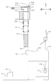
- FIG. 11 (a) shows a schematic diagram of the first stage of the splicing work of the tape.
- FIG. 11B shows a schematic diagram of the second stage of the tape splicing operation.
- FIG. 11C shows a schematic diagram of the third stage of the tape splicing operation.
- the operator cuts the vicinity of the front end 105c of the new tape 105 with a scissors 106 at a predetermined cutting position 105d. Similarly, the operator cuts the vicinity of the rear end 102c of the tape 102 in use with the scissors 106 at a predetermined cutting position 102d.
- the operator aligns the cutting position 105d of the new tape 105 with the cutting position 102d of the tape 102 in use.
- the operator connects the new tape 105 and the tape 102 in use by the splice tape 107. In this way, the splicing operation is executed.
- the splicing work is performed manually by the operator, it is complicated. Also, the operator may touch the adhesive surface of the splice tape 107 during work. For this reason, sweat, dirt, etc. may adhere and the adhesive force of the splice tape 107 may be weakened. In addition, the splicing accuracy depends on the skill level of the operator's skill.
- Patent Document 1 discloses a splicing device that performs splicing work without depending on the manual work of the operator.
- a pair of old and new tapes are set on a pair of tape holding bases.
- the pair of tape holding bases are reversed.
- the splice tape is attached to the upward surface (front surface) of the pair of old and new tapes.
- the pair of tape holding bases are reversed again.
- a splice tape is affixed on the upward surface (back surface) of a pair of new and old tapes. In this way, the splicing operation is performed.
- the splicing work can be easily executed.
- the operator is less likely to touch the adhesive surface of the splice tape 107 during work.
- the splicing accuracy is unlikely to depend on the skill level of the operator's skill.
- the splicing device described in the same document it is necessary to rotate a pair of tape holding bases, that is, a pair of old and new tapes, a plurality of times with respect to the stationary splicing tape during the splicing operation. For this reason, there is a possibility that the pair of old and new tapes may be displaced from each other. That is, the splicing accuracy may be reduced. In this case, the new tape may be bent and connected to the old tape like a broken line. In addition, at the joint between the old and new tapes, the pitch of the tape feed holes may be out of order.
- the splicing device of the present invention has been completed in view of the above problems.
- An object of the present invention is to provide a splicing device in which splicing accuracy is unlikely to decrease.
- the splicing device of the present invention can be switched between a fixed pressing member, an open position opened with respect to the fixed pressing member, and a closed position closed with respect to the fixed pressing member.
- a splicing tape disposed between the movable pressing member and the fixed pressing member at the open position.
- the first connecting end portion of the first tape and the second connecting end portion of the second tape are arranged, and the movable pressing member is switched from the open position to the closed position. Is closed with respect to the fixed pressing member, the movable pressing member overlaps the fixed pressing member in the front and back direction, and the splice stay is between the movable pressing member and the fixed pressing member. Is folded, the first connecting end and the second connecting end are sandwiched by the splice tape from the front and back directions, and the first connecting end and the second connecting end are connected.
- a splice tape is arranged so as to straddle the movable pressing member and the fixed pressing member. And the 1st connection end part of a 1st tape and the 2nd connection end part of a 2nd tape are arrange
- the surface of the splice tape is an adhesive surface. However, at this time, the back surface of the first connection end portion and the back surface of the second connection end portion may or may not be bonded to the bonding surface.
- the movable pressing member When moving from the open position to the closed position, the movable pressing member is closed with respect to the fixed pressing member. For this reason, the movable pressing member overlaps with the fixed pressing member in the front and back direction. At this time, the splice tape is folded between the movable pressing member and the fixed pressing member. Moreover, a 1st connection end part and a 2nd connection end part are clamped with the splice tape from the front and back direction. By being sandwiched, the surface of the first connecting end and the surface of the second connecting end are bonded to the back surface of the splice tape. In addition, the back surface of the first connection end and the back surface of the second connection end are bonded to the surface of the splice tape.
- the first connection end, and the second connection end, the first connection end and the second connection end are formed by the splice tape. Adheres firmly from the front and back. In this way, the first connecting end of the first tape and the second connecting end of the second tape are connected via the splice tape.
- the originally complicated splicing work can be easily executed. Further, the operator may touch the adhesive surface of the splice tape only when the splice tape, the first tape, and the second tape are set in the open position. For this reason, there is little possibility that an operator touches the adhesive surface of the splice tape. Therefore, there is little possibility that the adhesive force of the splice tape becomes weak. Also, the splicing accuracy is unlikely to depend on the skill level of the operator's skill.
- the splicing device of the present invention it is the splice tape that moves when the first tape, the second tape, and the splice tape are switched from the open position to the closed position. That is, the first connecting end of the first tape and the second connecting end of the second tape are both immobile. For this reason, in the splicing operation, the first connecting end and the second connecting end are unlikely to be displaced from each other. That is, the splicing accuracy is unlikely to decrease.
- the angle between the fixed pressing member and the movable pressing member at the open position is approximately 180 °. According to this configuration, the splice tape can be set without being bent in the open position.
- an operation unit that is operated by human power and supplies the movable pressing member with a driving force when switching from the open position to the closed position is provided.
- the splicing operation can be executed by the operator manually moving the operation unit. For this reason, even when there is no supply of electricity, the splicing operation can be executed with high accuracy.
- the movable pressing member when the actual moving amount of the movable pressing member has not reached the predetermined moving amount that can connect the first connecting end and the second connecting end, the movable pressing member does not return. In other words, the movable pressing member does not return unless the connection between the first connection end and the second connection end is completed. For this reason, splicing work can be executed reliably.
- the first connecting end and the second connecting end are connected by the splice tape in the closed position of the tape connecting portion.
- the first connecting end portion and the second connecting end portion are positioned with respect to the splice tape.
- the positioning portion can accurately and easily position the splice tape, the first connection end, and the second connection end.
- the splice tape includes a first hole row including a plurality of first positioning holes arranged in a longitudinal direction of the splice tape, and a short direction of the first hole row.
- a plurality of second hole rows arranged in parallel with each other in the longitudinal direction of the splice tape, and the first tape has a plurality of first feed holes arranged in the longitudinal direction of the first tape.
- the second tape has a plurality of second feed holes arranged in the longitudinal direction of the second tape, and the positioning portion is disposed in the fixed pressing member, and in the open position, from the back side A first positioning hole, a fixed positioning pin to be inserted into the first feeding hole and the second feeding hole, and the movable pressing member; and at the open position, the first positioning hole is inserted into the second positioning hole from the back side; Switch from the open position to the closed position When, better to adopt a configuration having a movable positioning pin inserted from the front side to the said first feed holes and said second feeding hole.
- the fixed positioning pin of the positioning part is inserted into the first positioning hole, the first feeding hole, and the second feeding hole from the back side, so that the splice tape and the first connecting end are located with respect to the positioning part.
- the part and the second connecting end are fixed.
- the splicing tape is fixed to the positioning portion by inserting the movable positioning pin of the positioning portion into the second positioning hole from the back side.
- the movable positioning pin When switching from the open position to the closed position, the movable positioning pin is inserted into the first feed hole and the second feed hole from the front side in addition to the already inserted second positioning hole. For this reason, a splice tape, a 1st connection end part, and a 2nd connection end part are positioned with respect to a positioning part from the front and back direction. In this state, the first connecting end and the second connecting end are connected by the splice tape. According to this configuration, the splicing tape, the first connecting end, and the second connecting end can be accurately and easily positioned by the positioning portion.
- FIG. 1 is a perspective view of a splicing device as an embodiment of the splicing device of the present invention.
- FIG. 2 is an exploded perspective view of the splicing device.
- FIG. 3 is a transparent right side view of the splicing device.
- FIG. 4 is an exploded transparent right side view of the splicing device.
- FIG. 5 is an exploded view of the lower part of FIG. 6 is an exploded view of the middle part of FIG.
- FIG. 7 is an exploded view of the upper part of FIG.
- FIG. 8 is a perspective view of the splicing device at the open position of the fixed pressing member and the movable pressing member.
- FIG. 9 is a transparent side view in the middle of switching from the open position to the closed position of the splicing device.
- FIG. 10 is a transparent right side view of the splicing device in a closed position.
- FIG. 11A is a schematic diagram of the first stage of the splicing work of the tape.
- FIG. 11B is a schematic diagram of the second stage of the tape splicing operation.
- FIG. 11C is a schematic diagram of a third stage of the tape splicing operation.
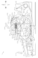
- FIG. 1 shows a perspective view of the splicing device of the present embodiment.
- FIG. 2 shows an exploded perspective view of the splicing device.
- FIG. 3 shows a transparent right side view of the splicing device.
- FIG. 4 shows an exploded transparent right side view of the splicing device.
- FIG. 5 shows an exploded view of the lower part of FIG.
- FIG. 6 shows an exploded view of the middle part of FIG.
- FIG. 7 shows an exploded view of the upper part of FIG.
- the splicing device 1 includes a tape connecting portion 2, an operation portion 3, a backward movement portion 32, a restriction portion 5, a base 6, and a link portion 7. .
- the base 6 includes a stopper 61 and a pair of brackets 62.
- the base 6 has a flat plate shape.
- the stopper 61 has a rectangular parallelepiped block shape.
- the stopper 61 is disposed on the upper surface of the front portion of the base 6.
- the stopper 61 sets a bottom dead center of the operation unit 3 described later.
- the pair of brackets 62 are disposed on the upper surface of the rear end portion of the base 6. From the left surface (outer surface) of the left bracket 62 and the right surface (outer surface) of the right bracket 62, swinging shafts 620 are projected.
- the operation unit 3 includes a pressing unit 30 and a pair of arms 31.
- Each of the pair of arms 31 has a thin plate shape extending in the front-rear direction.
- the pair of arms 31 are spaced apart in the left-right direction.
- the pressing part 30 has a flat plate shape.
- the pressing part 30 is constructed between the front ends of the pair of arms 31.
- a pressing force is input to the pressing unit 30 from the operator.
- a pair of swing shafts 620 are inserted into the rear ends of the pair of arms 31. Therefore, the operation unit 3 can swing around the swing shaft 620.
- Each of the pair of arms 31 includes a guide hole 310.
- Each of the pair of guide holes 310 has a long hole shape that is long in the front-rear direction.
- a rocking shaft 311 protrudes from the left surface of the right arm 31.
- the return movement part 32 is a so-called return spring.
- the return movement portion 32 is mounted on the swing shaft 620. One end of the return movement portion 32 is in elastic contact with the upper surface of the base 6. The other end of the return portion 32 is in elastic contact with the rear end of the arm 31.
- the backward movement portion 32 urges the operation portion 3 in a direction away from the base 6.
- the restriction unit 5 includes a restriction member 50, a pawl member 51, a bracket 52, and a spring 53.
- the regulating member 50 has a standing wall shape.
- the regulating member 50 is fixed to the right surface of the base 6 (shown by hatching in FIG. 2).
- the restricting member 50 is disposed between the base 6 and the right arm 31.
- a plurality of regulating teeth 500 are formed on the front edge of the regulating member 50.
- the bracket 52 is disposed on the left surface of the right arm 31.
- the pawl member 51 is inserted into the swing shaft 311.
- the pawl member 51 can swing around the swing shaft 311.
- an obtuse angle non-engaging portion 511 is disposed in the upper rear corner of the pawl member 51.
- a right-angle engaging portion 510 is disposed in the lower rear corner of the pawl member 51.
- the spring 53 is interposed between the bracket 52 and the front end of the pawl member 51. The spring 53 urges the pawl member 51 forward.
- the pawl member 51 can move only from above to below with respect to the restriction tooth 500.
- the pawl member 51 is movable from below to above with respect to the restriction tooth 500.
- the tape connecting portion 2 includes a fixed pressing member 20, a movable pressing member 21, a positioning portion 22, a fixing block 23, a pair of guide shafts 24, a pair of springs 25, a pair of retaining pins 26, and a pair.
- the support part 27 is provided.
- Each of the pair of guide shafts 24 has a round bar shape extending in the vertical direction.
- the guide shaft 24 protrudes from the upper surface of the base 6.
- the pair of guide shafts 24 are arranged in the left-right direction.
- a planar pressure contact surface 240 is disposed on each of the upper end front surfaces of the pair of guide shafts 24.
- the fixed block 23 has a rectangular parallelepiped shape.
- the fixed block 23 includes a pair of shaft insertion holes 230 and a pair of bushes 231.
- the pair of shaft insertion holes 230 penetrates the fixed block 23 in the vertical direction.
- the pair of shaft insertion holes 230 are arranged in the left-right direction.
- the guide shafts 24 are inserted through the pair of shaft insertion holes 230, respectively.
- Each of the pair of bushes 231 is fitted into an upper portion of the shaft insertion hole 230.
- Each of the pair of springs 25 is inserted into the shaft insertion hole 230.
- the lower ends of the pair of springs 25 are in elastic contact with the upper surface of the base 6.
- the upper ends of the pair of springs 25 are in elastic contact with the lower ends of the bushes 231, respectively.
- the pair of springs 25 urges the entire tape connecting portion 2 (excluding the pair of guide shafts 24) upward.
- the fixed pressing member 20 has a rectangular parallelepiped plate shape.
- the fixed pressing member 20 is disposed above the fixed block 23.
- the fixed pressing member 20 includes a pair of shaft housing recesses 200 and a pair of shaft retaining holes 201.
- the pair of shaft housing recesses 200 are recessed in the lower surface of the fixed pressing member 20.
- a pair of shaft accommodation recessed parts 200 are located in a line with the left-right direction.
- the upper ends of the pair of guide shafts 24 are housed in the pair of shaft housing recesses 200.
- the pair of shaft retaining holes 201 are formed in the front surface of the fixed pressing member 20.
- the rear ends of the pair of shaft retaining holes 201 communicate with the shaft accommodating recess 200, respectively.
- the pair of retaining pins 26 are screwed into the pair of shaft retaining holes 201.
- the rear ends of the pair of retaining pins 26 are in pressure contact with the pressure contact surfaces 240 of the guide shaft 24, respectively.
- the retaining pin 26 prevents the fixed pressing member 20 from coming out of the guide shaft 24 by the urging force of the spring 25.
- the fixed block 23 is movable in the vertical direction between the upper surface of the base 6 and the lower surface of the fixed pressing member 20. That is, the fixed block 23, a pair of support portions 27 to be described later, and a movable pressing member 21 to be described later are movable in the vertical direction while being urged by the spring 25. For this reason, when the movable pressing member 21 is switched from the open position to the closed position, the movable pressing member 21 can be pushed downward while resisting the biasing force of the spring 25.
- the movable pressing member 21 has a rectangular parallelepiped plate shape. As shown in FIG. 2, the movable pressing member 21 is juxtaposed behind the fixed pressing member 20 in the open position. The movable pressing member 21 is movable from the open position to a closed position that is inverted above the fixed pressing member 20 and juxtaposed in the vertical direction.
- the movable pressing member 21 includes a pair of drive connecting portions 210, a pair of guided portions 211, and a pair of tape support portions 212.
- the pair of drive connecting portions 210 are provided so as to protrude from both the left and right sides of the rear end of the movable pressing member 21.
- the pair of guided portions 211 are provided so as to protrude from both the left and right sides of the front end of the movable pressing member 21.
- the pair of tape support portions 212 protrude from the upper surface of the front end of the movable pressing member 21.
- each of the first tape and the second tape to be connected has a C-shaped winding hook that opens downward. In the open position, the first tape and the second tape get over the pair of tape support portions 212 by using this curl, and are set on the fixed pressing member 20.
- the members constituting the positioning portion 22 are divided into a fixed pressing member 20 and a movable pressing member 21.
- the positioning unit 22 includes a plurality of fixed positioning pins 220, a plurality of movable positioning pins 221, a plurality of fixed positioning holes 222, and a plurality of movable positioning holes 223.
- the plurality of fixed positioning pins 220 and the plurality of fixed positioning holes 222 are disposed in the rear portion of the fixed pressing member 20.
- the plurality of fixed positioning pins 220 and the plurality of fixed positioning holes 222 are arranged in a line in the left-right direction.
- the plurality of fixed positioning pins 220 and the plurality of fixed positioning holes 222 are alternately arranged.
- the plurality of movable positioning pins 221 and the plurality of movable positioning holes 223 are arranged in the front portion of the movable pressing member 21.
- the plurality of movable positioning pins 221 and the plurality of movable positioning holes 223 are arranged in a line in the left-right direction.
- the plurality of movable positioning pins 221 and the plurality of movable positioning holes 223 are alternately arranged.
- the movable positioning pin 221 and the fixed positioning hole 222 are opposed to each other in the front-rear direction.
- the fixed positioning pin 220 and the movable positioning hole 223 are opposed to each other in the front-rear direction.
- the movable positioning pin 221 can enter the fixed positioning hole 222 when switching from the open position to the closed position. Further, the fixed positioning pin 220 can enter the movable positioning hole 223.
- Each of the pair of support portions 27 has a standing wall shape.
- the pair of support portions 27 are fixed to the left and right walls of the fixed block 23 as shown by hatching in FIG.
- Each of the pair of support portions 27 includes a guide portion 270 and swing shafts 271 and 272.
- the pair of guide portions 270 are disposed on the right surface (inner surface) of the left support portion 27 and on the left surface (inner surface) of the right support portion 27.
- the guide part 270 has a C-shaped groove shape when viewed from the left or right side.
- a pair of guided portions 211 are accommodated in the pair of guide portions 270.
- the guided portion 211 is movable in the guide portion 270 along the shape of the guide portion 270.
- the pair of swing shafts 271 are disposed on the left surface (outer surface) of the left support portion 27 and the right surface (outer surface) of the right support portion 27.
- the pair of swing shafts 271 are respectively disposed in the upper front portion of the support portion 27.
- the pair of swing shafts 272 are disposed on the left surface (outer surface) of the left support portion 27 and the right surface (outer surface) of the right support portion 27.
- the pair of swing shafts 272 are respectively disposed in the upper center portion of the support portion 27.
- the link unit 7 includes a pair of first link members 70, a pair of second link members 71, and a pair of third link members 72.
- the pair of first link members 70, the pair of second link members 71, and the pair of third link members 72 are separately arranged on the outer sides in the left-right direction of the pair of support portions 27.
- the configuration and movement of the first link member 70, the second link member 71 and the third link member 72 on the left side are the configuration and movement of the first link member 70, the second link member 71 and the third link member 72 on the right side, It is the same.
- the arrangement of the first link member 70, the second link member 71, and the third link member 72 on the left side is symmetrical to the arrangement of the first link member 70, the second link member 71, and the third link member 72 on the right side. .
- the structure and movement of the right first link member 70, the second link member 71, and the third link member 72 will be described below as representative of these link members.
- the first link member 70 has a triangular plate shape when viewed from the left or right side.
- a swing shaft 271 is inserted from the left at the rear end of the first link member 70. Therefore, the first link member 70 can swing around the swing shaft 271.
- a guided projection 700 is fixed to the front end of the first link member 70 from the right side through a guide hole 310 of the arm 31.
- a connecting shaft 701 projects from the right surface of the lower end of the first link member 70.
- the second link member 71 has a C-shaped plate shape when viewed from the left or right side.
- a connecting shaft 701 is inserted into the C-shaped one end (front end) of the second link member 71 from the left. Therefore, the second link member 71 can swing with respect to the first link member 70.
- the third link member 72 is L-shaped when viewed from the left or right side.
- a swing shaft 272 is inserted into the L-shaped end (front end) of the third link member 72 from the left. For this reason, the third link member 72 can swing around the swing shaft 272.
- a connecting shaft 720 protrudes from the right surface of the L-shaped bent portion of the third link member 72.
- the connecting shaft 720 is inserted into the C-shaped other end (rear end) of the second link member 71.
- the third link member 72 can swing relative to the second link member 71.
- the drive connecting portion 210 is inserted into the L-shaped other end (rear end) of the third link member 72 from the left side. For this reason, the third link member 72 can swing with respect to the movable pressing member 21.
- FIG. 8 shows a perspective view of the splicing device of the present embodiment at the open position of the fixed pressing member and the movable pressing member.
- the splice tape 9 includes a protective film 90, a front surface adhesive tape 91, a back surface adhesive tape 92, a first hole array 93, and a second hole array 94.
- the protective film 90 has a rectangular thin film shape.
- the upper surface of the protective film 90 is an adhesive surface.
- the surface adhesive tape 91 has a strip shape extending in the left-right direction (longitudinal direction).
- the front surface adhesive tape 91 is disposed on the rear portion of the upper surface of the protective film 90 (upper surface portion of the movable pressing member 21).
- the upper surface of the front surface adhesive tape 91 is an adhesive surface.
- the back surface adhesive tape 92 has a strip shape extending in the left-right direction.
- the back surface adhesive tape 92 is disposed on the front portion of the upper surface of the protective film 90 (upper surface portion of the fixed pressing member 20).
- the upper surface of the back surface adhesive tape 92 is an adhesive surface.
- the first hole row 93 includes a total of eight first positioning holes 930.
- the first hole row 93 extends in the left-right direction.
- the first hole row 93 is disposed in the front portion of the upper surface of the protective film 90.
- the first positioning hole 930 passes through the vicinity of the rear edge of the back surface adhesive tape 92 and the protective film 90 in the vertical direction (front and back direction). Fixed positioning pins 220 are inserted into the eight first positioning holes 930 from every other side.
- the second hole row 94 includes a total of eight second positioning holes 940.
- the second hole row 94 extends in the left-right direction.
- the second hole row 94 is disposed in the rear portion of the upper surface of the protective film 90.
- the second positioning hole 940 penetrates the protective film 90 in the vertical direction. In the eight second positioning holes 940, movable positioning pins 221 are inserted from every other side.
- the first tape 80 includes a carrier tape 800, a pair of upper and lower cover tapes 801 (shown transparent in FIG. 8 for convenience of explanation), a large number of first feed holes 802, and a large number of component accommodating portions 803. It is equipped with.
- a number of first feed holes 802 are formed in the carrier tape 800.
- the multiple first feed holes 802 are arranged at a predetermined pitch along the left-right direction of the carrier tape 800.
- a large number of component housing portions 803 are formed in the carrier tape 800.
- a large number of component housing portions 803 are arranged at a predetermined pitch along the left-right direction of the carrier tape 800.
- a pair of front and back cover tapes 801 seals the upper and lower openings of the component housing portion 803.
- the component storage unit 803 can store electronic components (not shown).
- a first connection end 804 is disposed at the right end of the first tape 80.
- the configuration of the second tape 81 is the same as the configuration of the first tape 80. That is, the second tape 81 includes a carrier tape 810, a pair of upper and lower cover tapes 811, a large number of second feed holes 812, and a large number of component accommodating portions 813.
- a second connection end 814 is disposed at the left end of the second tape 81. The second connection end 814 and the first connection end 804 are in contact with each other in the left-right direction.
- FIG. 9 shows a transparent right side view of the splicing device in the closed position. 9 and 10 correspond to FIG.
- the operator sets the splice tape 9, the first tape 80, and the second tape 81 in the open position as shown in FIG. Specifically, first, the operator places the splice tape 9 on the upper surface of the fixed pressing member 20 and the upper surface of the movable pressing member 21. At this time, the fixed positioning pin 220 is inserted into the first positioning hole 930. Further, the movable positioning pin 221 is inserted into the second positioning hole 940. In this way, the splice tape 9 is positioned with respect to the fixed pressing member 20 and the movable pressing member 21.
- the operator places the first tape 80 on the left side portion of the splice tape 9.
- the first tape 80 has a C-shaped curl that opens downward.
- the first tape 80 is set on the fixed pressing member 20 through the tape support 212 on the left side.
- the fixed positioning pin 220 is inserted into the first feed hole 802.
- the operator places the second tape 81 on the right side portion of the splice tape 9.
- the second tape 81 has a C-shaped curl that opens downward.
- the second tape 81 is set on the fixed pressing member 20 over the right tape support portion 212.
- the fixed positioning pin 220 is inserted into the second feed hole 812. In this way, the first tape 80 and the second tape 81 are positioned with respect to the splice tape 9.
- the operator switches the movable pressing member 21 from the open position to the closed position as shown in FIGS. Specifically, the operator depresses the pressing unit 30 of the operation unit 3. As indicated by an arrow Y1 in FIG. 9, the operation unit 3 swings downward about the swing shaft 620. At this time, the urging force is accumulated in the backward movement portion 32. As indicated by an arrow Y2 in FIG. 9, when the operation portion 3 swings, the guided projection 700 moves backward in the guide hole 310. As indicated by an arrow Y3 in FIG. 9, when the guided projection 700 moves rearward, the first link member 70 swings counterclockwise about the swing shaft 271. As indicated by an arrow Y4 in FIG.
- the pawl member 51 gets over the restriction tooth 500 from the upper side to the lower side.
- the pawl member 51 is pulled from the front by a spring 53. Therefore, as shown by an arrow Y8 in FIG. 9, the pawl member 51 is biased in the clockwise direction. Therefore, even if the operator releases his / her hand from the pressing portion 30 while switching from the open position to the closed position, the engaging portion 510 is engaged with the restricting tooth 500, so that the pawl member 51 is restricted from below to above.
- the tooth 500 is not climbed over. That is, the operation unit 3 does not return to the state shown in FIG.
- the operating portion 3 swings downward about the swing shaft 620 until the pressing portion 30 contacts the stopper 61. . At this time, the urging force is further accumulated in the backward movement portion 32. Further, as shown by an arrow Y12 in FIG. 10, the guided projection 700 reaches the rear end of the guide hole 310. Further, as indicated by an arrow Y13 in FIG. 10, the first link member 70 swings further counterclockwise about the swing shaft 271. Further, as indicated by an arrow Y14 in FIG. 10, the second link member 71 swings counterclockwise. Further, as indicated by an arrow Y15 in FIG. 10, the third link member 72 swings counterclockwise.
- the guided portion 211 reaches the upper end of the guide portion 270.
- the movable pressing member 21 is reversed and the splice tape 9 is folded. Then, the first tape 80 and the second tape 81 are sandwiched by the folded splice tape 9 from the front and back directions.
- the fixed block 23, the pair of support portions 27, and the movable pressing member 21 are movable in the vertical direction while being urged by the spring 25. Therefore, as shown in FIG. 10, when the movable pressing member 21 is switched from the open position to the closed position, the movable pressing member 21 can be pushed downward while resisting the biasing force of the spring 25.
- the fixed pressing member 20 is fixed to the guide shaft 24 by a retaining pin 26. For this reason, the fixed pressing member 20 does not move. Therefore, the first tape 80 and the second tape 81 can be firmly sandwiched between the movable pressing member 21 and the fixed pressing member 20 by the splice tape 9 from the front and back directions.
- the adhesive tape 91 for the surface of the splice tape 9 is bonded to the upper surface of the first tape 80 and the upper surface of the second tape 81.
- the adhesive tape 92 for the back surface of the splice tape 9 is bonded to the lower surface of the first tape 80 and the lower surface of the second tape 81.
- the movable positioning pin 221 is inserted into the first feed hole 802 of the first tape 80 and the second feed hole 812 of the second tape 81 from the front side. For this reason, the 1st tape 80 and the 2nd tape 81 can be connected in the state positioned and pinched from the front and back directions.
- the pawl member 51 is pulled from the front by a spring 53. For this reason, when the pressing portion 30 comes into contact with the stopper 61, the pawl member 51 moves to below the regulating tooth 500 as indicated by an arrow Y19 in FIG.
- the operating unit 3 swings upward by the biasing force accumulated in the backward moving unit 32. That is, the movable pressing member 21 is switched from the closed position shown in FIG. 10 to the open position shown in FIG.
- the splice tape 9 remains on the fixed pressing member 20 side due to the adhesive force.
- the engaging portion 510 of the pawl member 51 does not engage with the restriction tooth 500.
- the non-engaging portion 511 of the pawl member 51 only traces the restriction tooth 500. In this way, even when the operator releases his / her hand from the operation unit 3 during the switching from the open position to the closed position, the movable pressing member 21 does not return to the open position. On the other hand, after the operator completely switches from the open position to the closed position, when the operator releases his hand from the operation unit 3, the movable pressing member 21 returns to the open position.
- the protective film 90 of the splice tape 9 is peeled off from the connected first tape 80 and second tape 81. In this way, the splicing operation is executed.
- the splicing device 1 of the present embodiment the originally complicated splicing work can be easily executed.
- the operator may touch the adhesive surface of the splice tape 9 only when the splice tape 9, the first tape 80, and the second tape 81 are set in the open position. For this reason, there is little possibility that an operator touches the adhesive surface of the splice tape 9. Therefore, there is little possibility that the adhesive force of the splice tape 9 becomes weak. Also, the splicing accuracy is unlikely to depend on the skill level of the operator's skill.
- the splicing device 1 of this embodiment only the splice tape 9 moves when the first tape 80, the second tape 81, and the splice tape 9 are switched from the open position to the closed position. That is, both the first connecting end 804 of the first tape 80 and the second connecting end 814 of the second tape 81 are immobile. For this reason, during the splicing operation, the first connecting end 804 and the second connecting end 814 are unlikely to be displaced from each other. That is, the splicing accuracy is unlikely to decrease.
- the operator can execute the splicing work by manually moving the operation unit 3. For this reason, even when there is no supply of electricity, the splicing operation can be executed with high accuracy.
- the operation unit 3 even if the operator releases his / her hand from the pressing unit 30 while switching from the open position to the closed position, the operation unit 3 will return to the state of FIG. Absent.
- the operating portion 3 swings upward by the biasing force accumulated in the backward moving portion 32. That is, the operation unit 3 returns to the state shown in FIG.
- the movable pressing member 21 is not switched from the closed position to the open position unless the connection between the first connection end 804 and the second connection end 814 is completed. For this reason, splicing work can be executed reliably.
- the splicing device 1 of the present embodiment when the operator releases his hand from the operation unit 3, the splicing operation is completed if the operation unit 3 automatically moves back. On the other hand, when the operator releases his / her hand from the operation unit 3, the splicing work is not completed unless the operation unit 3 automatically moves back. In this way, the operator can easily recognize whether or not the splicing work has been completed. In addition, it is possible to suppress a decrease in splicing accuracy due to insufficient adhesive force (when the moving amount of the movable pressing member 21 is insufficient).
- the fixed positioning pin 220 of the positioning portion 22 in the open position, is inserted into the first positioning hole 930, the first feed hole 802, and the second feed hole 812 from below.
- the splice tape 9, the first connection end 804, and the second connection end 814 are fixed to the positioning portion 22.
- the splicing tape 9 is fixed to the positioning portion 22 by inserting the movable positioning pin 221 of the positioning portion 22 into the second positioning hole 940 from below.
- the movable positioning pin 221 is inserted into the first feed hole 802 and the second feed hole 812 from above in addition to the already inserted second positioning hole 940.
- the splice tape 9, the first connecting end 804, and the second connecting end 814 are positioned with respect to the positioning portion 22 from the front and back directions. In this state, the first connecting end 804 and the second connecting end 814 are connected by the splice tape 9.
- the positioning portion 22 can accurately and easily position the splice tape 9, the first connection end 804, and the second connection end 814. Can do.
- the trajectory of the drive connecting portion 210 (rear end) of the movable pressing member 21 is determined by the link portion 7.
- the track of the guided portion 211 (front end) of the movable pressing member 21 is determined by the guide portion 270.
- the splicing device 1 of the present embodiment almost all the parts of the splicing device 1 are accommodated between the pressing portion 30 and the swing shaft 620 when viewed from the left or right.
- the tape connecting portion 2, the backward moving portion 32, the restricting portion 5, and the link portion 7 are contained within the swing radius of the operation portion 3. For this reason, the splicing apparatus 1 can be reduced in size.
- the upper surface of the fixed pressing member 20 and the upper surface of the movable pressing member 21 do not overlap the pressing portion 30 in the vertical direction at the open position. For this reason, it is easy to set the splice tape 9, the first tape 80, and the second tape 81.
- the movable pressing member 21 can be pushed downward while resisting the urging force of the spring 25 as shown in FIGS. For this reason, the first tape 80 and the second tape 81 can be firmly sandwiched from the front and back sides by the splice tape 9.
- the included angle between the fixed pressing member 20 and the movable pressing member 21 (the opening degree of the movable pressing member 21) in the open position is approximately. It is set to 180 °. For this reason, the splice tape 9 can be set without being bent.
- the first tape 80 and the second tape 81 are wound around the pair of tape support portions 212 using the winding tape.
- the one tape 80 and the second tape 81 can be set on the fixed pressing member 20.
- the 1st tape 80 and the 2nd tape 81 can be set easily.
- the pair of tape support portions 212 are integrally disposed on the movable pressing member 21. For this reason, when switching from the open position to the closed position, the pair of tape support portions 212 are reversed by approximately 180 ° together with the movable pressing member 21. Therefore, there is no possibility that the pair of tape support portions 212 interferes with the splicing work.
- the first link member 70, the second link member 71, and the third link member 72 are arranged on both sides in the left-right direction of the tape connecting portion 2. For this reason, compared with the case where each link member is arrange
- the fixed positioning pin 220 can enter the movable positioning hole 223 in the closed position. Further, the movable positioning pin 221 can enter the fixed positioning hole 222. For this reason, the space
- the first hole row 93 and the second hole row 94 are arranged near the center in the front-rear direction of the splice tape 9.
- the first hole row 93 and the second hole row 94 may be arranged near both front and rear edges of the splice tape 9. That is, the first hole row 93 and the second hole row 94 may be arranged so as to correspond to the arrangement of the first feed holes 802 and the second feed holes 812.
- the splice tape 9 may be replaced according to the type of the first tape 80 and the second tape 81.
- the movable pressing member 21, the fixed pressing member 20, the fixed positioning pin 220, and the movable positioning pin 221 may be replaced according to the types of the first tape 80, the second tape 81, and the splice tape 9.
- the movable pressing member 21 is driven by human power, but the movable pressing member 21 may be driven by a motor, a solenoid, a ball screw, a fluid (oil, air, etc.) cylinder, or the like. That is, electric power may be used.
- the driving force is transmitted from the operation unit 3 to the movable pressing member 21 by the link unit 7, but the driving force is transmitted from the operating unit 3 to the movable pressing member by another power transmission mechanism (for example, a cam mechanism). 21 may be transmitted.
- another power transmission mechanism for example, a cam mechanism
- the opening degree of the movable pressing member 21 relative to the fixed pressing member 20 in the open position is set to approximately 180 °.
- the opening is not particularly limited. For example, it may be 90 °, 180 °, 270 °, or the like.
Abstract
The present invention addresses the problem of providing a splicing device less susceptible to a decline in splicing accuracy. A splicing device (1) is provided with a tape junction (2) having a fixed retaining member (20) and a movable retaining member (21) that is able to switch between an open position open with respect to the fixed retaining member (20) and a closed position closed with respect to the fixed retaining member (20). The present invention is characterized in that switching from the open position to the closed position closes the movable retaining member (21) with respect to the fixed retaining member (20), and the movable retaining member (21) overlaps onto the fixed retaining member (20) in the front/back direction, a splice tape (9) is folded in between the movable retaining member (21) and the fixed retaining member (20), a first joining end (804) and a second joining end (814) are held sandwiched by the splice tape (9) from the front/rear direction, and the first joining end (804) and the second joining end (814) are joined together.
Description
本発明は、例えば電子部品実装機に電子部品を供給するテープフィーダーにおいて、旧テープに新テープを継ぎ足す際に用いられる、スプライシング装置に関する。
The present invention relates to a splicing device used when, for example, a new tape is added to an old tape in a tape feeder that supplies electronic components to an electronic component mounting machine.
電子部品実装機には、テープフィーダーが装着されている。テープフィーダーには、テープが巻装されている。テープには、多数の電子部品が、長手方向に所定間隔ずつ離間して、収容されている。テープから基板に電子部品が装着されるのに従って、テープの電子部品は徐々に少なくなっていく。電子部品の残量が所定量以下になった古いテープには、同じ部品種の電子部品を有する新しいテープが、連結される。当該連結作業をスプライシング作業という。
The tape feeder is mounted on the electronic component mounting machine. Tape is wound around the tape feeder. A large number of electronic components are accommodated in the tape at predetermined intervals in the longitudinal direction. As electronic components are mounted on the substrate from the tape, the number of electronic components on the tape gradually decreases. A new tape having an electronic component of the same component type is connected to an old tape in which the remaining amount of the electronic component is equal to or less than a predetermined amount. This connection work is called splicing work.
図11(a)に、テープのスプライシング作業の第一段階の模式図を示す。図11(b)に、テープのスプライシング作業の第二段階の模式図を示す。図11(c)に、テープのスプライシング作業の第三段階の模式図を示す。
FIG. 11 (a) shows a schematic diagram of the first stage of the splicing work of the tape. FIG. 11B shows a schematic diagram of the second stage of the tape splicing operation. FIG. 11C shows a schematic diagram of the third stage of the tape splicing operation.
スプライシング作業においては、まず、図11(a)に示すように、作業者が、新しいテープ105の先端105c付近を、ハサミ106により、所定の切断位置105dで、切断する。同様に、作業者が、使用中のテープ102の後端102c付近を、ハサミ106により、所定の切断位置102dで、切断する。
In the splicing work, first, as shown in FIG. 11A, the operator cuts the vicinity of the front end 105c of the new tape 105 with a scissors 106 at a predetermined cutting position 105d. Similarly, the operator cuts the vicinity of the rear end 102c of the tape 102 in use with the scissors 106 at a predetermined cutting position 102d.
次に、図11(b)に示すように、作業者が、新しいテープ105の切断位置105dと、使用中のテープ102の切断位置102dと、を位置合わせする。それから、図11(c)に示すように、作業者が、スプライステープ107により、新しいテープ105と、使用中のテープ102と、を連結する。このようにして、スプライシング作業は実行される。
Next, as shown in FIG. 11B, the operator aligns the cutting position 105d of the new tape 105 with the cutting position 102d of the tape 102 in use. Then, as shown in FIG. 11C, the operator connects the new tape 105 and the tape 102 in use by the splice tape 107. In this way, the splicing operation is executed.
しかしながら、スプライシング作業は、作業者の手作業により行われるため、煩雑である。また、作業時に、スプライステープ107の接着面を、作業者が触ってしまうおそれがある。このため、汗や汚れなどが付着して、スプライステープ107の接着力が弱くなるおそれがある。また、スプライシング精度が、作業者のスキルの熟練度に依存してしまう。
However, since the splicing work is performed manually by the operator, it is complicated. Also, the operator may touch the adhesive surface of the splice tape 107 during work. For this reason, sweat, dirt, etc. may adhere and the adhesive force of the splice tape 107 may be weakened. In addition, the splicing accuracy depends on the skill level of the operator's skill.
この点、特許文献1には、作業者の手作業によらずに、スプライシング作業を行うスプライシング装置が開示されている。同文献記載のスプライシング装置によりスプライシング作業を行う場合は、まず、一対のテープ保持ベースに、新旧一対のテープをセットする。次に、一対のテープ保持ベースを反転させる。続いて、スプライステープを、新旧一対のテープの上向きの面(表面)に貼り付ける。それから、再び、一対のテープ保持ベースを反転させる。そして、スプライステープを、新旧一対のテープの上向きの面(裏面)に貼り付ける。このようにして、スプライシング作業を行う。同文献記載のスプライシング装置によると、簡単にスプライシング作業を実行することができる。また、作業時に、スプライステープ107の接着面を、作業者が触ってしまうおそれが小さい。また、スプライシング精度が、作業者のスキルの熟練度に依存しにくい。
In this regard, Patent Document 1 discloses a splicing device that performs splicing work without depending on the manual work of the operator. When performing the splicing operation with the splicing device described in the document, first, a pair of old and new tapes are set on a pair of tape holding bases. Next, the pair of tape holding bases are reversed. Subsequently, the splice tape is attached to the upward surface (front surface) of the pair of old and new tapes. Then, the pair of tape holding bases are reversed again. And a splice tape is affixed on the upward surface (back surface) of a pair of new and old tapes. In this way, the splicing operation is performed. According to the splicing device described in the document, the splicing work can be easily executed. In addition, the operator is less likely to touch the adhesive surface of the splice tape 107 during work. Also, the splicing accuracy is unlikely to depend on the skill level of the operator's skill.
ところが、同文献記載のスプライシング装置によると、スプライシング作業の際、不動のスプライステープに対して、一対のテープ保持ベースつまり新旧一対のテープを、複数回、回転させる必要がある。このため、新旧一対のテープが、互いに位置ずれを起こすおそれがある。すなわち、スプライシング精度が低下するおそれがある。この場合、旧テープに対して、新テープが、折れ線のように、屈曲して連結されるおそれがある。また、新旧一対のテープの継ぎ目において、テープの送り孔のピッチが狂ってしまうおそれがある。
However, according to the splicing device described in the same document, it is necessary to rotate a pair of tape holding bases, that is, a pair of old and new tapes, a plurality of times with respect to the stationary splicing tape during the splicing operation. For this reason, there is a possibility that the pair of old and new tapes may be displaced from each other. That is, the splicing accuracy may be reduced. In this case, the new tape may be bent and connected to the old tape like a broken line. In addition, at the joint between the old and new tapes, the pitch of the tape feed holes may be out of order.
本発明のスプライシング装置は、上記課題に鑑みて完成されたものである。本発明は、スプライシング精度が低下しにくいスプライシング装置を提供することを目的とする。
The splicing device of the present invention has been completed in view of the above problems. An object of the present invention is to provide a splicing device in which splicing accuracy is unlikely to decrease.
(1)上記課題を解決するため、本発明のスプライシング装置は、固定押さえ部材と、該固定押さえ部材に対して開く開位置と、該固定押さえ部材に対して閉じる閉位置と、に切替可能な可動押さえ部材と、を有するテープ連結部を備え、該開位置において、該可動押さえ部材と該固定押さえ部材とに跨るように、スプライステープが配置され、該開位置において、該スプライステープのうち該固定押さえ部材側の部分の表面に、第一テープの第一連結端部と第二テープの第二連結端部とが配置され、該開位置から該閉位置に切り替わることにより、該可動押さえ部材が該固定押さえ部材に対して閉じられ、該可動押さえ部材が該固定押さえ部材に対して表裏方向に重なり、該可動押さえ部材と該固定押さえ部材との間に該スプライステープが折り込まれ、該第一連結端部と該第二連結端部とが表裏方向から該スプライステープにより挟持され、該第一連結端部と該第二連結端部とが連結されることを特徴とする。
(1) In order to solve the above-described problem, the splicing device of the present invention can be switched between a fixed pressing member, an open position opened with respect to the fixed pressing member, and a closed position closed with respect to the fixed pressing member. A splicing tape disposed between the movable pressing member and the fixed pressing member at the open position. On the surface of the fixed pressing member side portion, the first connecting end portion of the first tape and the second connecting end portion of the second tape are arranged, and the movable pressing member is switched from the open position to the closed position. Is closed with respect to the fixed pressing member, the movable pressing member overlaps the fixed pressing member in the front and back direction, and the splice stay is between the movable pressing member and the fixed pressing member. Is folded, the first connecting end and the second connecting end are sandwiched by the splice tape from the front and back directions, and the first connecting end and the second connecting end are connected. And
開位置においては、可動押さえ部材と固定押さえ部材とに跨るように、スプライステープが配置される。並びに、スプライステープのうち固定押さえ部材側の部分の表面に、第一テープの第一連結端部と、第二テープの第二連結端部と、が配置される。なお、スプライステープの表面は、接着面である。ただし、この時点においては、第一連結端部の裏面および第二連結端部の裏面は、当該接着面に接着されていても、接着されていなくてもよい。
In the open position, a splice tape is arranged so as to straddle the movable pressing member and the fixed pressing member. And the 1st connection end part of a 1st tape and the 2nd connection end part of a 2nd tape are arrange | positioned at the surface of the part at the side of the fixed pressing member among splice tapes. The surface of the splice tape is an adhesive surface. However, at this time, the back surface of the first connection end portion and the back surface of the second connection end portion may or may not be bonded to the bonding surface.
開位置から閉位置に切り替わる際、可動押さえ部材は、固定押さえ部材に対して、閉じられる。このため、可動押さえ部材は、固定押さえ部材に対して、表裏方向に重なる。この際、可動押さえ部材と固定押さえ部材との間に、スプライステープが折り込まれる。また、第一連結端部と第二連結端部とが、表裏方向からスプライステープにより挟持される。挟持されることにより、第一連結端部の表面、第二連結端部の表面は、スプライステープの裏面に接着される。並びに、第一連結端部の裏面、第二連結端部の裏面は、スプライステープの表面に接着される。また、スプライステープと第一連結端部と第二連結端部との積層体に対して、表裏方向から挟持力が加わるため、第一連結端部、第二連結端部は、スプライステープにより、表裏方向からしっかりと接着される。このようにして、第一テープの第一連結端部と第二テープの第二連結端部とが、スプライステープを介して、連結される。
When moving from the open position to the closed position, the movable pressing member is closed with respect to the fixed pressing member. For this reason, the movable pressing member overlaps with the fixed pressing member in the front and back direction. At this time, the splice tape is folded between the movable pressing member and the fixed pressing member. Moreover, a 1st connection end part and a 2nd connection end part are clamped with the splice tape from the front and back direction. By being sandwiched, the surface of the first connecting end and the surface of the second connecting end are bonded to the back surface of the splice tape. In addition, the back surface of the first connection end and the back surface of the second connection end are bonded to the surface of the splice tape. In addition, since a clamping force is applied from the front and back direction to the laminate of the splice tape, the first connection end, and the second connection end, the first connection end and the second connection end are formed by the splice tape. Adheres firmly from the front and back. In this way, the first connecting end of the first tape and the second connecting end of the second tape are connected via the splice tape.
本発明のスプライシング装置によると、本来煩雑なスプライシング作業を、簡単に実行することができる。また、スプライステープの接着面を作業者が触るおそれがあるのは、開位置において、スプライステープと第一テープと第二テープとをセットする際のみである。このため、スプライステープの接着面を作業者が触るおそれが小さい。したがって、スプライステープの接着力が弱くなるおそれが小さい。また、スプライシング精度が、作業者のスキルの熟練度に依存しにくい。
According to the splicing device of the present invention, the originally complicated splicing work can be easily executed. Further, the operator may touch the adhesive surface of the splice tape only when the splice tape, the first tape, and the second tape are set in the open position. For this reason, there is little possibility that an operator touches the adhesive surface of the splice tape. Therefore, there is little possibility that the adhesive force of the splice tape becomes weak. Also, the splicing accuracy is unlikely to depend on the skill level of the operator's skill.
また、本発明のスプライシング装置によると、第一テープ、第二テープ、スプライステープのうち、開位置から閉位置に切り替わる際に移動するのは、スプライステープである。すなわち、第一テープの第一連結端部、第二テープの第二連結端部は、共に不動である。このため、スプライシング作業の際、第一連結端部と第二連結端部とが、互いに位置ずれを起こしにくい。すなわち、スプライシング精度が低下しにくい。
Further, according to the splicing device of the present invention, it is the splice tape that moves when the first tape, the second tape, and the splice tape are switched from the open position to the closed position. That is, the first connecting end of the first tape and the second connecting end of the second tape are both immobile. For this reason, in the splicing operation, the first connecting end and the second connecting end are unlikely to be displaced from each other. That is, the splicing accuracy is unlikely to decrease.
(1-1)好ましくは、上記(1)の構成において、前記開位置における、前記固定押さえ部材と前記可動押さえ部材との間の挟角は、略180°である構成とする方がよい。本構成によると、開位置において、スプライステープを折り曲げずにセットすることができる。
(1-1) Preferably, in the configuration of (1) above, it is preferable that the angle between the fixed pressing member and the movable pressing member at the open position is approximately 180 °. According to this configuration, the splice tape can be set without being bent in the open position.
(1-2)好ましくは、上記(1)の構成において、人力により操作され、前記可動押さえ部材に、前記開位置から前記閉位置に切り替わる際の駆動力を供給する操作部を備える構成とする方がよい。
(1-2) Preferably, in the configuration of (1), an operation unit that is operated by human power and supplies the movable pressing member with a driving force when switching from the open position to the closed position is provided. Better.
本構成によると、操作者が操作部を手動で動かすことにより、スプライシング作業を実行することができる。このため、電気の供給がない場合であっても、精度よくスプライシング作業を実行することができる。
本 According to this configuration, the splicing operation can be executed by the operator manually moving the operation unit. For this reason, even when there is no supply of electricity, the splicing operation can be executed with high accuracy.
(2)好ましくは、上記(1)の構成において、前記可動押さえ部材を自動的に前記閉位置から前記開位置に復動させる復動部と、該開位置から該閉位置に切り替わる際に、前記第一連結端部と前記第二連結端部とを連結可能な所定移動量に対して、該可動押さえ部材の実際の移動量が達していない場合に、該復動部による該可動押さえ部材の復動を規制する規制部と、を備える構成とする方がよい。
(2) Preferably, in the configuration of (1) above, when the movable pressing member is automatically moved from the closed position back to the open position, and when switching from the open position to the closed position, When the actual moving amount of the movable pressing member has not reached the predetermined moving amount that can connect the first connecting end portion and the second connecting end portion, the movable pressing member by the return portion It is better to have a configuration including a regulating unit that regulates the backward movement of the motor.
本構成によると、第一連結端部と第二連結端部とを連結可能な所定移動量に対して、可動押さえ部材の実際の移動量が達していない場合、可動押さえ部材が復動しない。言い換えると、第一連結端部と第二連結端部との連結が完了しなければ、可動押さえ部材が復動しない。このため、確実にスプライシング作業を実行することができる。
According to this configuration, when the actual moving amount of the movable pressing member has not reached the predetermined moving amount that can connect the first connecting end and the second connecting end, the movable pressing member does not return. In other words, the movable pressing member does not return unless the connection between the first connection end and the second connection end is completed. For this reason, splicing work can be executed reliably.
特に、本構成と上記(1-2)の構成とを組み合わせる場合、人力による可動押さえ部材の移動量が充分か不充分かを、操作者が簡単に認識することができる。また、接着力不足(可動押さえ部材の移動量が不充分な場合)によるスプライシング精度の低下を、抑制することができる。
In particular, when this configuration is combined with the above configuration (1-2), the operator can easily recognize whether the amount of movement of the movable pressing member by human power is sufficient or insufficient. Further, it is possible to suppress a decrease in splicing accuracy due to insufficient adhesive force (when the amount of movement of the movable pressing member is insufficient).
(3)好ましくは、上記(1)または(2)の構成において、前記テープ連結部は、前記閉位置において、前記スプライステープにより該第一連結端部と該第二連結端部とが連結される際に、該スプライステープに対して前記第一連結端部と前記第二連結端部とを位置決めする、位置決め部を備える構成とする方がよい。
(3) Preferably, in the configuration of the above (1) or (2), the first connecting end and the second connecting end are connected by the splice tape in the closed position of the tape connecting portion. In this case, it is preferable that the first connecting end portion and the second connecting end portion are positioned with respect to the splice tape.
スプライシング作業においては、スプライステープに対して、第一連結端部と第二連結端部とを正確に位置決めする必要がある。しかしながら、三つの部材(スプライステープ、第一テープ、第二テープ)の位置決め作業は煩雑である。この点、本構成によると、位置決め部により、スプライステープと、第一連結端部と、第二連結端部と、を正確に、また簡単に位置決めすることができる。
In splicing work, it is necessary to accurately position the first connecting end and the second connecting end with respect to the splice tape. However, the positioning operation of the three members (splice tape, first tape, and second tape) is complicated. In this regard, according to the present configuration, the positioning portion can accurately and easily position the splice tape, the first connection end, and the second connection end.
(4)好ましくは、上記(3)の構成において、前記スプライステープは、該スプライステープの長手方向に並ぶ複数の第一位置決め孔からなる第一孔列と、該第一孔列の短手方向に並置され該スプライステープの長手方向に並ぶ複数の第二位置決め孔からなる第二孔列と、を有し、前記第一テープは、該第一テープの長手方向に並ぶ複数の第一送り孔を有し、前記第二テープは、該第二テープの長手方向に並ぶ複数の第二送り孔を有し、前記位置決め部は、前記固定押さえ部材に配置され、前記開位置において、裏側から該第一位置決め孔と該第一送り孔と該第二送り孔とに挿入される固定位置決めピンと、前記可動押さえ部材に配置され、該開位置において、裏側から該第二位置決め孔に挿入され、該開位置から前記閉位置に切り替わる際に、表側から該第一送り孔と該第二送り孔とに挿入される可動位置決めピンと、を有する構成とする方がよい。
(4) Preferably, in the configuration of (3), the splice tape includes a first hole row including a plurality of first positioning holes arranged in a longitudinal direction of the splice tape, and a short direction of the first hole row. A plurality of second hole rows arranged in parallel with each other in the longitudinal direction of the splice tape, and the first tape has a plurality of first feed holes arranged in the longitudinal direction of the first tape. And the second tape has a plurality of second feed holes arranged in the longitudinal direction of the second tape, and the positioning portion is disposed in the fixed pressing member, and in the open position, from the back side A first positioning hole, a fixed positioning pin to be inserted into the first feeding hole and the second feeding hole, and the movable pressing member; and at the open position, the first positioning hole is inserted into the second positioning hole from the back side; Switch from the open position to the closed position When, better to adopt a configuration having a movable positioning pin inserted from the front side to the said first feed holes and said second feeding hole.
開位置においては、位置決め部の固定位置決めピンが、裏側から、第一位置決め孔、第一送り孔、第二送り孔に挿入されることにより、位置決め部に対して、スプライステープと第一連結端部と第二連結端部とが固定される。また、位置決め部の可動位置決めピンが、裏側から、第二位置決め孔に挿入されることにより、位置決め部に対して、スプライステープが固定される。
In the open position, the fixed positioning pin of the positioning part is inserted into the first positioning hole, the first feeding hole, and the second feeding hole from the back side, so that the splice tape and the first connecting end are located with respect to the positioning part. The part and the second connecting end are fixed. Moreover, the splicing tape is fixed to the positioning portion by inserting the movable positioning pin of the positioning portion into the second positioning hole from the back side.
開位置から閉位置に切り替わる際、可動位置決めピンは、既に挿入済みの第二位置決め孔に加えて、表側から、第一送り孔、第二送り孔に挿入される。このため、位置決め部に対して、スプライステープと第一連結端部と第二連結端部とが、表裏方向から位置決めされる。この状態において、スプライステープにより、第一連結端部と第二連結端部とが連結される。本構成によると、位置決め部により、スプライステープと、第一連結端部と、第二連結端部と、を正確に、また簡単に位置決めすることができる。
When switching from the open position to the closed position, the movable positioning pin is inserted into the first feed hole and the second feed hole from the front side in addition to the already inserted second positioning hole. For this reason, a splice tape, a 1st connection end part, and a 2nd connection end part are positioned with respect to a positioning part from the front and back direction. In this state, the first connecting end and the second connecting end are connected by the splice tape. According to this configuration, the splicing tape, the first connecting end, and the second connecting end can be accurately and easily positioned by the positioning portion.
本発明によると、スプライシング精度が低下しにくいスプライシング装置を提供することができる。
According to the present invention, it is possible to provide a splicing device in which splicing accuracy is unlikely to decrease.
1:スプライシング装置、2:テープ連結部、3:操作部、5:規制部、6:ベース、7:リンク部、9:スプライステープ。
20:固定押さえ部材、21:可動押さえ部材、22:位置決め部、23:固定ブロック、24:ガイドシャフト、25:スプリング、26:抜け止めピン、27:支持部、30:押圧部、31:アーム、32:復動部、50:規制部材、51:歯止め部材、52:ブラケット、53:スプリング、61:ストッパ、62:ブラケット、70:第一リンク部材、71:第二リンク部材、72:第三リンク部材、80:第一テープ、81:第二テープ、90:保護フィルム、91:表面用粘着テープ、92:裏面用粘着テープ、93:第一孔列、94:第二孔列。
200:シャフト収容凹部、201:シャフト抜け止め孔、210:駆動連結部、211:被ガイド部、212:テープ支持部、220:固定位置決めピン、221:可動位置決めピン、222:固定位置決め孔、223:可動位置決め孔、230:シャフト挿通孔、231:ブッシュ、240:被圧接面、270:ガイド部、271:揺動軸、272:揺動軸、310:ガイド孔、311:揺動軸、500:規制歯、510:係合部、511:非係合部、620:揺動軸、700:被ガイド突起、701:連結軸、720:連結軸、800:キャリアテープ、801:カバーテープ、802:第一送り孔、803:部品収容部、804:第一連結端部、810:キャリアテープ、811:カバーテープ、812:第二送り孔、813:部品収容部、814:第二連結端部、930:第一位置決め孔、940:第二位置決め孔。 1: splicing device, 2: tape connecting part, 3: operating part, 5: regulating part, 6: base, 7: link part, 9: splicing tape.
20: fixed pressing member, 21: movable pressing member, 22: positioning portion, 23: fixed block, 24: guide shaft, 25: spring, 26: retaining pin, 27: support portion, 30: pressing portion, 31: arm , 32: backward movement part, 50: restriction member, 51: pawl member, 52: bracket, 53: spring, 61: stopper, 62: bracket, 70: first link member, 71: second link member, 72: first Three link members, 80: first tape, 81: second tape, 90: protective film, 91: front surface adhesive tape, 92: back surface adhesive tape, 93: first hole row, 94: second hole row.
200: Shaft receiving recess, 201: Shaft retaining hole, 210: Drive connecting part, 211: Guided part, 212: Tape support part, 220: Fixed positioning pin, 221: Movable positioning pin, 222: Fixed positioning hole, 223 : Movable positioning hole, 230: shaft insertion hole, 231: bush, 240: pressure contact surface, 270: guide portion, 271: swing shaft, 272: swing shaft, 310: guide hole, 311: swing shaft, 500 : Restriction tooth, 510: engagement portion, 511: non-engagement portion, 620: swing shaft, 700: guided projection, 701: connection shaft, 720: connection shaft, 800: carrier tape, 801: cover tape, 802 : First feed hole, 803: component accommodating portion, 804: first connecting end, 810: carrier tape, 811: cover tape, 812: second feed hole, 813: component Description section, 814: second connecting end portion, 930: first positioning hole, 940: second positioning hole.
以下、本発明のスプライシング装置の実施の形態について説明する。
Hereinafter, embodiments of the splicing device of the present invention will be described.
<スプライシング装置の構成>
まず、本実施形態のスプライシング装置の構成について説明する。図1に、本実施形態のスプライシング装置の斜視図を示す。図2に、同スプライシング装置の分解斜視図を示す。図3に、同スプライシング装置の透過右面図を示す。図4に、同スプライシング装置の分解透過右面図を示す。図5に、図4の下段部分の分解図を示す。図6に、図4の中段部分の分解図を示す。図7に、図4の上段部分の分解図を示す。図1~図7に示すように、スプライシング装置1は、テープ連結部2と、操作部3と、復動部32と、規制部5と、ベース6と、リンク部7と、を備えている。 <Configuration of splicing device>
First, the configuration of the splicing device of this embodiment will be described. FIG. 1 shows a perspective view of the splicing device of the present embodiment. FIG. 2 shows an exploded perspective view of the splicing device. FIG. 3 shows a transparent right side view of the splicing device. FIG. 4 shows an exploded transparent right side view of the splicing device. FIG. 5 shows an exploded view of the lower part of FIG. FIG. 6 shows an exploded view of the middle part of FIG. FIG. 7 shows an exploded view of the upper part of FIG. As shown in FIGS. 1 to 7, thesplicing device 1 includes a tape connecting portion 2, an operation portion 3, a backward movement portion 32, a restriction portion 5, a base 6, and a link portion 7. .
まず、本実施形態のスプライシング装置の構成について説明する。図1に、本実施形態のスプライシング装置の斜視図を示す。図2に、同スプライシング装置の分解斜視図を示す。図3に、同スプライシング装置の透過右面図を示す。図4に、同スプライシング装置の分解透過右面図を示す。図5に、図4の下段部分の分解図を示す。図6に、図4の中段部分の分解図を示す。図7に、図4の上段部分の分解図を示す。図1~図7に示すように、スプライシング装置1は、テープ連結部2と、操作部3と、復動部32と、規制部5と、ベース6と、リンク部7と、を備えている。 <Configuration of splicing device>
First, the configuration of the splicing device of this embodiment will be described. FIG. 1 shows a perspective view of the splicing device of the present embodiment. FIG. 2 shows an exploded perspective view of the splicing device. FIG. 3 shows a transparent right side view of the splicing device. FIG. 4 shows an exploded transparent right side view of the splicing device. FIG. 5 shows an exploded view of the lower part of FIG. FIG. 6 shows an exploded view of the middle part of FIG. FIG. 7 shows an exploded view of the upper part of FIG. As shown in FIGS. 1 to 7, the
[ベース6]
ベース6は、ストッパ61と、一対のブラケット62と、を備えている。ベース6は、平板状を呈している。ストッパ61は、直方体ブロック状を呈している。ストッパ61は、ベース6の前側部分の上面に配置されている。ストッパ61は、後述する操作部3の下死点を設定している。一対のブラケット62は、ベース6の後端部の上面に配置されている。左側のブラケット62の左面(外面)および右側のブラケット62の右面(外面)からは、各々、揺動軸620が突設されている。 [Base 6]
Thebase 6 includes a stopper 61 and a pair of brackets 62. The base 6 has a flat plate shape. The stopper 61 has a rectangular parallelepiped block shape. The stopper 61 is disposed on the upper surface of the front portion of the base 6. The stopper 61 sets a bottom dead center of the operation unit 3 described later. The pair of brackets 62 are disposed on the upper surface of the rear end portion of the base 6. From the left surface (outer surface) of the left bracket 62 and the right surface (outer surface) of the right bracket 62, swinging shafts 620 are projected.
ベース6は、ストッパ61と、一対のブラケット62と、を備えている。ベース6は、平板状を呈している。ストッパ61は、直方体ブロック状を呈している。ストッパ61は、ベース6の前側部分の上面に配置されている。ストッパ61は、後述する操作部3の下死点を設定している。一対のブラケット62は、ベース6の後端部の上面に配置されている。左側のブラケット62の左面(外面)および右側のブラケット62の右面(外面)からは、各々、揺動軸620が突設されている。 [Base 6]
The
[操作部3、復動部32]
操作部3は、押圧部30と、一対のアーム31と、を備えている。一対のアーム31は、各々、前後方向に延在する細板状を呈している。一対のアーム31は、左右方向に離間して配置されている。押圧部30は、平板状を呈している。押圧部30は、一対のアーム31の前端間に架設されている。押圧部30には、操作者から押圧力が入力される。一対のアーム31の後端には、一対の揺動軸620が挿入されている。このため、操作部3は、揺動軸620を中心に、揺動可能である。一対のアーム31は、各々、ガイド孔310を備えている。一対のガイド孔310は、各々、前後方向に長い長孔状を呈している。右側のアーム31の左面からは、揺動軸311が突設されている。 [Operation unit 3, reverse movement unit 32]
Theoperation unit 3 includes a pressing unit 30 and a pair of arms 31. Each of the pair of arms 31 has a thin plate shape extending in the front-rear direction. The pair of arms 31 are spaced apart in the left-right direction. The pressing part 30 has a flat plate shape. The pressing part 30 is constructed between the front ends of the pair of arms 31. A pressing force is input to the pressing unit 30 from the operator. A pair of swing shafts 620 are inserted into the rear ends of the pair of arms 31. Therefore, the operation unit 3 can swing around the swing shaft 620. Each of the pair of arms 31 includes a guide hole 310. Each of the pair of guide holes 310 has a long hole shape that is long in the front-rear direction. A rocking shaft 311 protrudes from the left surface of the right arm 31.
操作部3は、押圧部30と、一対のアーム31と、を備えている。一対のアーム31は、各々、前後方向に延在する細板状を呈している。一対のアーム31は、左右方向に離間して配置されている。押圧部30は、平板状を呈している。押圧部30は、一対のアーム31の前端間に架設されている。押圧部30には、操作者から押圧力が入力される。一対のアーム31の後端には、一対の揺動軸620が挿入されている。このため、操作部3は、揺動軸620を中心に、揺動可能である。一対のアーム31は、各々、ガイド孔310を備えている。一対のガイド孔310は、各々、前後方向に長い長孔状を呈している。右側のアーム31の左面からは、揺動軸311が突設されている。 [
The
復動部32は、いわゆるリターンスプリングである。復動部32は、揺動軸620に環装されている。復動部32の一端は、ベース6の上面に弾接している。復動部32の他端は、アーム31の後端に弾接している。復動部32は、操作部3を、ベース6から離間する方向に付勢している。
The return movement part 32 is a so-called return spring. The return movement portion 32 is mounted on the swing shaft 620. One end of the return movement portion 32 is in elastic contact with the upper surface of the base 6. The other end of the return portion 32 is in elastic contact with the rear end of the arm 31. The backward movement portion 32 urges the operation portion 3 in a direction away from the base 6.
[規制部5]
規制部5は、規制部材50と、歯止め部材51と、ブラケット52と、スプリング53と、を備えている。規制部材50は立壁状を呈している。規制部材50は、ベース6の右面(図2にハッチングで示す。)に固定されている。規制部材50は、ベース6と右側のアーム31との間に配置されている。規制部材50の前縁には、複数の規制歯500が形成されている。 [Regulatory Section 5]
Therestriction unit 5 includes a restriction member 50, a pawl member 51, a bracket 52, and a spring 53. The regulating member 50 has a standing wall shape. The regulating member 50 is fixed to the right surface of the base 6 (shown by hatching in FIG. 2). The restricting member 50 is disposed between the base 6 and the right arm 31. A plurality of regulating teeth 500 are formed on the front edge of the regulating member 50.
規制部5は、規制部材50と、歯止め部材51と、ブラケット52と、スプリング53と、を備えている。規制部材50は立壁状を呈している。規制部材50は、ベース6の右面(図2にハッチングで示す。)に固定されている。規制部材50は、ベース6と右側のアーム31との間に配置されている。規制部材50の前縁には、複数の規制歯500が形成されている。 [Regulatory Section 5]
The
ブラケット52は、右側のアーム31の左面に配置されている。歯止め部材51は、揺動軸311に挿入されている。歯止め部材51は、揺動軸311を中心に、揺動可能である。歯止め部材51の後上隅には、鈍角の非係合部511が配置されている。歯止め部材51の後下隅には、直角の係合部510が配置されている。スプリング53は、ブラケット52と歯止め部材51の前端との間に介装されている。スプリング53は、歯止め部材51を前方に付勢している。
The bracket 52 is disposed on the left surface of the right arm 31. The pawl member 51 is inserted into the swing shaft 311. The pawl member 51 can swing around the swing shaft 311. In the upper rear corner of the pawl member 51, an obtuse angle non-engaging portion 511 is disposed. In the lower rear corner of the pawl member 51, a right-angle engaging portion 510 is disposed. The spring 53 is interposed between the bracket 52 and the front end of the pawl member 51. The spring 53 urges the pawl member 51 forward.
後述するように、可動押さえ部材21を開位置から閉位置に切り替える際、規制歯500に対して、歯止め部材51は、上方から下方に向かってのみ、移動可能である。一方、閉位置に完全に到達した後、可動押さえ部材21を閉位置から開位置に切り替える際、規制歯500に対して、歯止め部材51は、下方から上方に向かって移動可能である。
As will be described later, when the movable pressing member 21 is switched from the open position to the closed position, the pawl member 51 can move only from above to below with respect to the restriction tooth 500. On the other hand, when the movable pressing member 21 is switched from the closed position to the open position after completely reaching the closed position, the pawl member 51 is movable from below to above with respect to the restriction tooth 500.
[テープ連結部2]
テープ連結部2は、固定押さえ部材20と、可動押さえ部材21と、位置決め部22と、固定ブロック23と、一対のガイドシャフト24と、一対のスプリング25と、一対の抜け止めピン26と、一対の支持部27と、を備えている。 [Tape connecting part 2]
Thetape connecting portion 2 includes a fixed pressing member 20, a movable pressing member 21, a positioning portion 22, a fixing block 23, a pair of guide shafts 24, a pair of springs 25, a pair of retaining pins 26, and a pair. The support part 27 is provided.
テープ連結部2は、固定押さえ部材20と、可動押さえ部材21と、位置決め部22と、固定ブロック23と、一対のガイドシャフト24と、一対のスプリング25と、一対の抜け止めピン26と、一対の支持部27と、を備えている。 [Tape connecting part 2]
The
一対のガイドシャフト24は、各々、上下方向に延在する丸棒状を呈している。ガイドシャフト24は、ベース6の上面から突設されている。一対のガイドシャフト24は、左右方向に並んでいる。一対のガイドシャフト24の上端前面には、各々、平面状の被圧接面240が配置されている。
Each of the pair of guide shafts 24 has a round bar shape extending in the vertical direction. The guide shaft 24 protrudes from the upper surface of the base 6. The pair of guide shafts 24 are arranged in the left-right direction. A planar pressure contact surface 240 is disposed on each of the upper end front surfaces of the pair of guide shafts 24.
固定ブロック23は、直方体状を呈している。固定ブロック23は、一対のシャフト挿通孔230と、一対のブッシュ231と、を備えている。一対のシャフト挿通孔230は、固定ブロック23を、上下方向に貫通している。一対のシャフト挿通孔230は、左右方向に並んでいる。一対のシャフト挿通孔230には、各々、ガイドシャフト24が挿通されている。一対のブッシュ231は、各々、シャフト挿通孔230の上方部分に嵌合されている。
The fixed block 23 has a rectangular parallelepiped shape. The fixed block 23 includes a pair of shaft insertion holes 230 and a pair of bushes 231. The pair of shaft insertion holes 230 penetrates the fixed block 23 in the vertical direction. The pair of shaft insertion holes 230 are arranged in the left-right direction. The guide shafts 24 are inserted through the pair of shaft insertion holes 230, respectively. Each of the pair of bushes 231 is fitted into an upper portion of the shaft insertion hole 230.
一対のスプリング25は、各々、シャフト挿通孔230に挿入されている。一対のスプリング25の下端は、各々、ベース6の上面に弾接している。一対のスプリング25の上端は、各々、ブッシュ231の下端に弾接している。一対のスプリング25は、テープ連結部2全体(一対のガイドシャフト24を除く)を、上方に付勢している。
Each of the pair of springs 25 is inserted into the shaft insertion hole 230. The lower ends of the pair of springs 25 are in elastic contact with the upper surface of the base 6. The upper ends of the pair of springs 25 are in elastic contact with the lower ends of the bushes 231, respectively. The pair of springs 25 urges the entire tape connecting portion 2 (excluding the pair of guide shafts 24) upward.
固定押さえ部材20は、直方体板状を呈している。固定押さえ部材20は、固定ブロック23の上方に配置されている。固定押さえ部材20は、一対のシャフト収容凹部200と、一対のシャフト抜け止め孔201と、を備えている。一対のシャフト収容凹部200は、固定押さえ部材20の下面に凹設されている。一対のシャフト収容凹部200は、左右方向に並んでいる。一対のシャフト収容凹部200には、一対のガイドシャフト24の上端が収容されている。一対のシャフト抜け止め孔201は、固定押さえ部材20の前面に穿設されている。一対のシャフト抜け止め孔201の後端は、各々、シャフト収容凹部200に連通している。
The fixed pressing member 20 has a rectangular parallelepiped plate shape. The fixed pressing member 20 is disposed above the fixed block 23. The fixed pressing member 20 includes a pair of shaft housing recesses 200 and a pair of shaft retaining holes 201. The pair of shaft housing recesses 200 are recessed in the lower surface of the fixed pressing member 20. A pair of shaft accommodation recessed parts 200 are located in a line with the left-right direction. The upper ends of the pair of guide shafts 24 are housed in the pair of shaft housing recesses 200. The pair of shaft retaining holes 201 are formed in the front surface of the fixed pressing member 20. The rear ends of the pair of shaft retaining holes 201 communicate with the shaft accommodating recess 200, respectively.
一対の抜け止めピン26は、一対のシャフト抜け止め孔201に螺合されている。一対の抜け止めピン26の後端は、各々、ガイドシャフト24の被圧接面240に圧接している。抜け止めピン26は、スプリング25の付勢力により、固定押さえ部材20がガイドシャフト24から抜け出すのを防止している。
The pair of retaining pins 26 are screwed into the pair of shaft retaining holes 201. The rear ends of the pair of retaining pins 26 are in pressure contact with the pressure contact surfaces 240 of the guide shaft 24, respectively. The retaining pin 26 prevents the fixed pressing member 20 from coming out of the guide shaft 24 by the urging force of the spring 25.
図4に示すように、固定ブロック23は、ベース6の上面と、固定押さえ部材20の下面と、の間で上下方向に移動可能である。すなわち、固定ブロック23、後述する一対の支持部27、後述する可動押さえ部材21は、スプリング25に付勢された状態で、上下方向に移動可能である。このため、可動押さえ部材21を開位置から閉位置に切り替える際に、スプリング25の付勢力に抗しながら、可動押さえ部材21を下方に押し込むことができる。
As shown in FIG. 4, the fixed block 23 is movable in the vertical direction between the upper surface of the base 6 and the lower surface of the fixed pressing member 20. That is, the fixed block 23, a pair of support portions 27 to be described later, and a movable pressing member 21 to be described later are movable in the vertical direction while being urged by the spring 25. For this reason, when the movable pressing member 21 is switched from the open position to the closed position, the movable pressing member 21 can be pushed downward while resisting the biasing force of the spring 25.
可動押さえ部材21は、直方体板状を呈している。図2に示すように、開位置においては、可動押さえ部材21は、固定押さえ部材20の後方に並置されている。可動押さえ部材21は、当該開位置から、固定押さえ部材20の上方に反転して上下方向に並置される閉位置まで、移動可能である。可動押さえ部材21は、一対の駆動連結部210と、一対の被ガイド部211と、一対のテープ支持部212と、を備えている。一対の駆動連結部210は、可動押さえ部材21の後端の左右両面から、突設されている。一対の被ガイド部211は、可動押さえ部材21の前端の左右両面から、突設されている。一対のテープ支持部212は、可動押さえ部材21の前端の上面から、突設されている。
The movable pressing member 21 has a rectangular parallelepiped plate shape. As shown in FIG. 2, the movable pressing member 21 is juxtaposed behind the fixed pressing member 20 in the open position. The movable pressing member 21 is movable from the open position to a closed position that is inverted above the fixed pressing member 20 and juxtaposed in the vertical direction. The movable pressing member 21 includes a pair of drive connecting portions 210, a pair of guided portions 211, and a pair of tape support portions 212. The pair of drive connecting portions 210 are provided so as to protrude from both the left and right sides of the rear end of the movable pressing member 21. The pair of guided portions 211 are provided so as to protrude from both the left and right sides of the front end of the movable pressing member 21. The pair of tape support portions 212 protrude from the upper surface of the front end of the movable pressing member 21.
後述するように、連結対象である第一テープ、第二テープは、各々、下方に開口するC字状の巻き癖を有している。開位置においては、この巻き癖を利用して、第一テープ、第二テープが、一対のテープ支持部212を乗り越えて、固定押さえ部材20にセットされる。
As will be described later, each of the first tape and the second tape to be connected has a C-shaped winding hook that opens downward. In the open position, the first tape and the second tape get over the pair of tape support portions 212 by using this curl, and are set on the fixed pressing member 20.
位置決め部22を構成する部材は、固定押さえ部材20と可動押さえ部材21とに分かれて配置されている。位置決め部22は、複数の固定位置決めピン220と、複数の可動位置決めピン221と、複数の固定位置決め孔222と、複数の可動位置決め孔223と、を備えている。
The members constituting the positioning portion 22 are divided into a fixed pressing member 20 and a movable pressing member 21. The positioning unit 22 includes a plurality of fixed positioning pins 220, a plurality of movable positioning pins 221, a plurality of fixed positioning holes 222, and a plurality of movable positioning holes 223.
複数の固定位置決めピン220、複数の固定位置決め孔222は、固定押さえ部材20の後側部分に配置されている。複数の固定位置決めピン220、複数の固定位置決め孔222は、左右方向に一列に並んでいる。複数の固定位置決めピン220、複数の固定位置決め孔222は、交互に配置されている。
The plurality of fixed positioning pins 220 and the plurality of fixed positioning holes 222 are disposed in the rear portion of the fixed pressing member 20. The plurality of fixed positioning pins 220 and the plurality of fixed positioning holes 222 are arranged in a line in the left-right direction. The plurality of fixed positioning pins 220 and the plurality of fixed positioning holes 222 are alternately arranged.
複数の可動位置決めピン221、複数の可動位置決め孔223は、可動押さえ部材21の前側部分に配置されている。複数の可動位置決めピン221、複数の可動位置決め孔223は、左右方向に一列に並んでいる。複数の可動位置決めピン221、複数の可動位置決め孔223は、交互に配置されている。
The plurality of movable positioning pins 221 and the plurality of movable positioning holes 223 are arranged in the front portion of the movable pressing member 21. The plurality of movable positioning pins 221 and the plurality of movable positioning holes 223 are arranged in a line in the left-right direction. The plurality of movable positioning pins 221 and the plurality of movable positioning holes 223 are alternately arranged.
可動位置決めピン221と固定位置決め孔222とは前後方向に対向している。固定位置決めピン220と可動位置決め孔223とは前後方向に対向している。開位置から閉位置に切り替わる際、可動位置決めピン221は固定位置決め孔222に進入可能である。また、固定位置決めピン220は可動位置決め孔223に進入可能である。
The movable positioning pin 221 and the fixed positioning hole 222 are opposed to each other in the front-rear direction. The fixed positioning pin 220 and the movable positioning hole 223 are opposed to each other in the front-rear direction. The movable positioning pin 221 can enter the fixed positioning hole 222 when switching from the open position to the closed position. Further, the fixed positioning pin 220 can enter the movable positioning hole 223.
一対の支持部27は、各々、立壁状を呈している。一対の支持部27は、図2にハッチングで示すように、固定ブロック23の左右両壁に固定されている。一対の支持部27は、各々、ガイド部270と、揺動軸271、272とを備えている。一対のガイド部270は、左側の支持部27の右面(内面)および右側の支持部27の左面(内面)に、配置されている。ガイド部270は、左側または右側から見てC字溝状を呈している。一対のガイド部270には、一対の被ガイド部211が収容されている。被ガイド部211は、ガイド部270内を、ガイド部270の形状に沿って、移動可能である。
Each of the pair of support portions 27 has a standing wall shape. The pair of support portions 27 are fixed to the left and right walls of the fixed block 23 as shown by hatching in FIG. Each of the pair of support portions 27 includes a guide portion 270 and swing shafts 271 and 272. The pair of guide portions 270 are disposed on the right surface (inner surface) of the left support portion 27 and on the left surface (inner surface) of the right support portion 27. The guide part 270 has a C-shaped groove shape when viewed from the left or right side. A pair of guided portions 211 are accommodated in the pair of guide portions 270. The guided portion 211 is movable in the guide portion 270 along the shape of the guide portion 270.
一対の揺動軸271は、左側の支持部27の左面(外面)および右側の支持部27の右面(外面)に、配置されている。一対の揺動軸271は、各々、支持部27の前上部分に配置されている。一対の揺動軸272は、左側の支持部27の左面(外面)および右側の支持部27の右面(外面)に、配置されている。一対の揺動軸272は、各々、支持部27の中央上部分に配置されている。
The pair of swing shafts 271 are disposed on the left surface (outer surface) of the left support portion 27 and the right surface (outer surface) of the right support portion 27. The pair of swing shafts 271 are respectively disposed in the upper front portion of the support portion 27. The pair of swing shafts 272 are disposed on the left surface (outer surface) of the left support portion 27 and the right surface (outer surface) of the right support portion 27. The pair of swing shafts 272 are respectively disposed in the upper center portion of the support portion 27.
[リンク部7]
リンク部7は、一対の第一リンク部材70と、一対の第二リンク部材71と、一対の第三リンク部材72と、を備えている。一対の第一リンク部材70、一対の第二リンク部材71、一対の第三リンク部材72は、一対の支持部27の左右方向外側に、分かれて配置されている。 [Link 7]
Thelink unit 7 includes a pair of first link members 70, a pair of second link members 71, and a pair of third link members 72. The pair of first link members 70, the pair of second link members 71, and the pair of third link members 72 are separately arranged on the outer sides in the left-right direction of the pair of support portions 27.
リンク部7は、一対の第一リンク部材70と、一対の第二リンク部材71と、一対の第三リンク部材72と、を備えている。一対の第一リンク部材70、一対の第二リンク部材71、一対の第三リンク部材72は、一対の支持部27の左右方向外側に、分かれて配置されている。 [Link 7]
The
左側の第一リンク部材70、第二リンク部材71、第三リンク部材72の構成、動きは、右側の第一リンク部材70、第二リンク部材71、第三リンク部材72の構成、動きと、同様である。左側の第一リンク部材70、第二リンク部材71、第三リンク部材72の配置は、右側の第一リンク部材70、第二リンク部材71、第三リンク部材72の配置と、左右対称である。このため、以下、これらのリンク部材を代表して、右側の第一リンク部材70、第二リンク部材71、第三リンク部材72の構成、動きについて説明する。
The configuration and movement of the first link member 70, the second link member 71 and the third link member 72 on the left side are the configuration and movement of the first link member 70, the second link member 71 and the third link member 72 on the right side, It is the same. The arrangement of the first link member 70, the second link member 71, and the third link member 72 on the left side is symmetrical to the arrangement of the first link member 70, the second link member 71, and the third link member 72 on the right side. . For this reason, the structure and movement of the right first link member 70, the second link member 71, and the third link member 72 will be described below as representative of these link members.
第一リンク部材70は、左側または右側から見て三角形板状を呈している。第一リンク部材70の後端には、左方から揺動軸271が挿入されている。このため、第一リンク部材70は、揺動軸271を中心に、揺動可能である。第一リンク部材70の前端には、アーム31のガイド孔310を介して、右方から被ガイド突起700が固定されている。第一リンク部材70の下端の右面からは、連結軸701が突設されている。
The first link member 70 has a triangular plate shape when viewed from the left or right side. A swing shaft 271 is inserted from the left at the rear end of the first link member 70. Therefore, the first link member 70 can swing around the swing shaft 271. A guided projection 700 is fixed to the front end of the first link member 70 from the right side through a guide hole 310 of the arm 31. A connecting shaft 701 projects from the right surface of the lower end of the first link member 70.
第二リンク部材71は、左側または右側から見てC字板状を呈している。第二リンク部材71のC字一端(前端)には、左方から連結軸701が挿入されている。このため、第二リンク部材71は、第一リンク部材70に対して、揺動可能である。
The second link member 71 has a C-shaped plate shape when viewed from the left or right side. A connecting shaft 701 is inserted into the C-shaped one end (front end) of the second link member 71 from the left. Therefore, the second link member 71 can swing with respect to the first link member 70.
第三リンク部材72は、左側または右側から見てL字板状を呈している。第三リンク部材72のL字一端(前端)には、左方から揺動軸272が挿入されている。このため、第三リンク部材72は、揺動軸272を中心に、揺動可能である。第三リンク部材72のL字屈曲部の右面からは、連結軸720が突設されている。連結軸720は、第二リンク部材71のC字他端(後端)に挿入されている。このため、第三リンク部材72は、第二リンク部材71に対して、揺動可能である。第三リンク部材72のL字他端(後端)には、左方から駆動連結部210が挿入されている。このため、第三リンク部材72は、可動押さえ部材21に対して、揺動可能である。
The third link member 72 is L-shaped when viewed from the left or right side. A swing shaft 272 is inserted into the L-shaped end (front end) of the third link member 72 from the left. For this reason, the third link member 72 can swing around the swing shaft 272. A connecting shaft 720 protrudes from the right surface of the L-shaped bent portion of the third link member 72. The connecting shaft 720 is inserted into the C-shaped other end (rear end) of the second link member 71. For this reason, the third link member 72 can swing relative to the second link member 71. The drive connecting portion 210 is inserted into the L-shaped other end (rear end) of the third link member 72 from the left side. For this reason, the third link member 72 can swing with respect to the movable pressing member 21.
<スプライステープ、第一テープ、第二テープの構成>
次に、スプライステープ、第一テープ、第二テープの構成について説明する。図8に、本実施形態のスプライシング装置の固定押さえ部材と可動押さえ部材との開位置における斜視図を示す。 <Configuration of splice tape, first tape, and second tape>
Next, the configuration of the splice tape, the first tape, and the second tape will be described. FIG. 8 shows a perspective view of the splicing device of the present embodiment at the open position of the fixed pressing member and the movable pressing member.
図8に示すように、スプライステープ9は、保護フィルム90と、表面用粘着テープ91と、裏面用粘着テープ92と、第一孔列93と、第二孔列94と、を備えている。保護フィルム90は、矩形薄膜状を呈している。保護フィルム90の上面は接着面である。
As shown in FIG. 8, the splice tape 9 includes a protective film 90, a front surface adhesive tape 91, a back surface adhesive tape 92, a first hole array 93, and a second hole array 94. The protective film 90 has a rectangular thin film shape. The upper surface of the protective film 90 is an adhesive surface.
表面用粘着テープ91は、左右方向(長手方向)に延びる帯状を呈している。表面用粘着テープ91は、保護フィルム90の上面の後方部分(可動押さえ部材21の上面部分)に配置されている。表面用粘着テープ91の上面は接着面である。
The surface adhesive tape 91 has a strip shape extending in the left-right direction (longitudinal direction). The front surface adhesive tape 91 is disposed on the rear portion of the upper surface of the protective film 90 (upper surface portion of the movable pressing member 21). The upper surface of the front surface adhesive tape 91 is an adhesive surface.
裏面用粘着テープ92は、左右方向に延びる帯状を呈している。裏面用粘着テープ92は、保護フィルム90の上面の前方部分(固定押さえ部材20の上面部分)に配置されている。裏面用粘着テープ92の上面は接着面である。
The back surface adhesive tape 92 has a strip shape extending in the left-right direction. The back surface adhesive tape 92 is disposed on the front portion of the upper surface of the protective film 90 (upper surface portion of the fixed pressing member 20). The upper surface of the back surface adhesive tape 92 is an adhesive surface.
第一孔列93は、合計8個の第一位置決め孔930からなる。第一孔列93は、左右方向に延在している。第一孔列93は、保護フィルム90の上面の前方部分に配置されている。第一位置決め孔930は、裏面用粘着テープ92の後縁付近と、保護フィルム90と、を上下方向(表裏方向)に貫通している。8個の第一位置決め孔930には、一つおきに、下方から固定位置決めピン220が挿入されている。
The first hole row 93 includes a total of eight first positioning holes 930. The first hole row 93 extends in the left-right direction. The first hole row 93 is disposed in the front portion of the upper surface of the protective film 90. The first positioning hole 930 passes through the vicinity of the rear edge of the back surface adhesive tape 92 and the protective film 90 in the vertical direction (front and back direction). Fixed positioning pins 220 are inserted into the eight first positioning holes 930 from every other side.
第二孔列94は、合計8個の第二位置決め孔940からなる。第二孔列94は、左右方向に延在している。第二孔列94は、保護フィルム90の上面の後方部分に配置されている。第二位置決め孔940は、保護フィルム90を上下方向に貫通している。8個の第二位置決め孔940には、一つおきに、下方から可動位置決めピン221が挿入されている。
The second hole row 94 includes a total of eight second positioning holes 940. The second hole row 94 extends in the left-right direction. The second hole row 94 is disposed in the rear portion of the upper surface of the protective film 90. The second positioning hole 940 penetrates the protective film 90 in the vertical direction. In the eight second positioning holes 940, movable positioning pins 221 are inserted from every other side.
第一テープ80は、キャリアテープ800と、上下一対のカバーテープ801(説明の便宜上、図8においては透過して示す。)と、多数の第一送り孔802と、多数の部品収容部803と、を備えている。多数の第一送り孔802は、キャリアテープ800に穿設されている。多数の第一送り孔802は、キャリアテープ800の左右方向に沿って、所定のピッチで配置されている。多数の部品収容部803は、キャリアテープ800に穿設されている。多数の部品収容部803は、キャリアテープ800の左右方向に沿って、所定のピッチで配置されている。表裏一対のカバーテープ801は、部品収容部803の上下開口を封止している。部品収容部803は、電子部品(図略)を収容可能である。第一テープ80の右端には、第一連結端部804が配置されている。
The first tape 80 includes a carrier tape 800, a pair of upper and lower cover tapes 801 (shown transparent in FIG. 8 for convenience of explanation), a large number of first feed holes 802, and a large number of component accommodating portions 803. It is equipped with. A number of first feed holes 802 are formed in the carrier tape 800. The multiple first feed holes 802 are arranged at a predetermined pitch along the left-right direction of the carrier tape 800. A large number of component housing portions 803 are formed in the carrier tape 800. A large number of component housing portions 803 are arranged at a predetermined pitch along the left-right direction of the carrier tape 800. A pair of front and back cover tapes 801 seals the upper and lower openings of the component housing portion 803. The component storage unit 803 can store electronic components (not shown). A first connection end 804 is disposed at the right end of the first tape 80.
第二テープ81の構成は、第一テープ80の構成と同様である。すなわち、第二テープ81は、キャリアテープ810と、上下一対のカバーテープ811と、多数の第二送り孔812と、多数の部品収容部813と、を備えている。第二テープ81の左端には、第二連結端部814が配置されている。第二連結端部814と第一連結端部804とは、左右方向に当接している。
The configuration of the second tape 81 is the same as the configuration of the first tape 80. That is, the second tape 81 includes a carrier tape 810, a pair of upper and lower cover tapes 811, a large number of second feed holes 812, and a large number of component accommodating portions 813. A second connection end 814 is disposed at the left end of the second tape 81. The second connection end 814 and the first connection end 804 are in contact with each other in the left-right direction.
<スプライシング作業>
次に、本実施形態のスプライシング装置を用いたスプライシング作業について説明する。図9に、本実施形態のスプライシング装置の開位置から閉位置に切り替える途中の透過側面図を示す。図10に、同スプライシング装置の閉位置における透過右面図を示す。なお、図9、図10は、図3に対応している。 <Splicing work>
Next, the splicing work using the splicing device of the present embodiment will be described. In FIG. 9, the permeation | transmission side view in the middle of switching from the open position of the splicing apparatus of this embodiment to a closed position is shown. FIG. 10 shows a transparent right side view of the splicing device in the closed position. 9 and 10 correspond to FIG.
まず、操作者は、開位置において、図8に示すように、スプライステープ9、第一テープ80、第二テープ81をセットする。具体的には、まず、操作者は、スプライステープ9を、固定押さえ部材20の上面および可動押さえ部材21の上面に配置する。この際、固定位置決めピン220を、第一位置決め孔930に挿入する。また、可動位置決めピン221を、第二位置決め孔940に挿入する。このようにして、固定押さえ部材20および可動押さえ部材21に対して、スプライステープ9を位置決めする。
First, the operator sets the splice tape 9, the first tape 80, and the second tape 81 in the open position as shown in FIG. Specifically, first, the operator places the splice tape 9 on the upper surface of the fixed pressing member 20 and the upper surface of the movable pressing member 21. At this time, the fixed positioning pin 220 is inserted into the first positioning hole 930. Further, the movable positioning pin 221 is inserted into the second positioning hole 940. In this way, the splice tape 9 is positioned with respect to the fixed pressing member 20 and the movable pressing member 21.
次に、操作者は、スプライステープ9の左側部分に、第一テープ80を配置する。第一テープ80は、下方に開口するC字状の巻き癖を有している。この巻き癖を利用して、第一テープ80を、左側のテープ支持部212越しに、固定押さえ部材20にセットする。また、固定位置決めピン220を、第一送り孔802に挿入する。同様に、操作者は、スプライステープ9の右側部分に、第二テープ81を配置する。第二テープ81は、下方に開口するC字状の巻き癖を有している。この巻き癖を利用して、第二テープ81を、右側のテープ支持部212越しに、固定押さえ部材20にセットする。また、固定位置決めピン220を、第二送り孔812に挿入する。このようにして、スプライステープ9に対して、第一テープ80および第二テープ81を位置決めする。
Next, the operator places the first tape 80 on the left side portion of the splice tape 9. The first tape 80 has a C-shaped curl that opens downward. Using this curl, the first tape 80 is set on the fixed pressing member 20 through the tape support 212 on the left side. Further, the fixed positioning pin 220 is inserted into the first feed hole 802. Similarly, the operator places the second tape 81 on the right side portion of the splice tape 9. The second tape 81 has a C-shaped curl that opens downward. Using this curl, the second tape 81 is set on the fixed pressing member 20 over the right tape support portion 212. Further, the fixed positioning pin 220 is inserted into the second feed hole 812. In this way, the first tape 80 and the second tape 81 are positioned with respect to the splice tape 9.
次に、操作者は、図3、図9、図10に示すように、可動押さえ部材21を開位置から閉位置に切り替える。具体的には、操作者は、操作部3の押圧部30を押し下げる。図9に矢印Y1で示すように、操作部3は、揺動軸620を中心に、下方に揺動する。この際、復動部32に付勢力が蓄積される。図9に矢印Y2で示すように、操作部3が揺動すると、被ガイド突起700が、ガイド孔310内を、後方に移動する。図9に矢印Y3で示すように、被ガイド突起700が後方に移動すると、第一リンク部材70が、揺動軸271を中心に、反時計回りに揺動する。図9に矢印Y4で示すように、第一リンク部材70が揺動すると、第二リンク部材71が後方に押し出される。図9に矢印Y5で示すように、第二リンク部材71が押し出されると、第三リンク部材72が、揺動軸272を中心に、反時計回りに揺動する。図9に矢印Y6で示すように、第三リンク部材72が揺動すると、被ガイド部211は、ガイド部270内を、ガイド部270の形状に沿って移動する。このため、被ガイド部211つまり可動押さえ部材21の前端は、下降する。一方、可動押さえ部材21の駆動連結部210は、第三リンク部材72の先端に連結されている。このため、駆動連結部210つまり可動押さえ部材21の後端は、上昇する。すなわち、可動押さえ部材21は、反時計回りに揺動する。
Next, the operator switches the movable pressing member 21 from the open position to the closed position as shown in FIGS. Specifically, the operator depresses the pressing unit 30 of the operation unit 3. As indicated by an arrow Y1 in FIG. 9, the operation unit 3 swings downward about the swing shaft 620. At this time, the urging force is accumulated in the backward movement portion 32. As indicated by an arrow Y2 in FIG. 9, when the operation portion 3 swings, the guided projection 700 moves backward in the guide hole 310. As indicated by an arrow Y3 in FIG. 9, when the guided projection 700 moves rearward, the first link member 70 swings counterclockwise about the swing shaft 271. As indicated by an arrow Y4 in FIG. 9, when the first link member 70 swings, the second link member 71 is pushed backward. As indicated by an arrow Y5 in FIG. 9, when the second link member 71 is pushed out, the third link member 72 swings counterclockwise about the swing shaft 272. As indicated by an arrow Y6 in FIG. 9, when the third link member 72 swings, the guided portion 211 moves within the guide portion 270 along the shape of the guide portion 270. For this reason, the guided portion 211, that is, the front end of the movable pressing member 21 is lowered. On the other hand, the drive connecting portion 210 of the movable pressing member 21 is connected to the tip of the third link member 72. For this reason, the drive coupling part 210, that is, the rear end of the movable pressing member 21 is raised. That is, the movable pressing member 21 swings counterclockwise.
また、操作部3の揺動に伴って、上方から下方に向かって、歯止め部材51が規制歯500を乗り越える。図9に矢印Y7で示すように、歯止め部材51は、スプリング53により、前方から引っ張られている。このため、図9に矢印Y8で示すように、歯止め部材51は、時計回り方向に付勢されている。したがって、開位置から閉位置に切り替えている途中で操作者が押圧部30から手を離しても、係合部510が規制歯500に噛合するため、下方から上方に向かって歯止め部材51が規制歯500を乗り越えることはない。すなわち、操作部3が図3の状態に復動することはない。
Further, as the operation unit 3 swings, the pawl member 51 gets over the restriction tooth 500 from the upper side to the lower side. As shown by an arrow Y <b> 7 in FIG. 9, the pawl member 51 is pulled from the front by a spring 53. Therefore, as shown by an arrow Y8 in FIG. 9, the pawl member 51 is biased in the clockwise direction. Therefore, even if the operator releases his / her hand from the pressing portion 30 while switching from the open position to the closed position, the engaging portion 510 is engaged with the restricting tooth 500, so that the pawl member 51 is restricted from below to above. The tooth 500 is not climbed over. That is, the operation unit 3 does not return to the state shown in FIG.
操作者がさらに押圧部30を押し下げると、図10に矢印Y11で示すように、操作部3は、押圧部30がストッパ61に当接するまで、揺動軸620を中心に、下方に揺動する。この際、さらに復動部32に付勢力が蓄積される。また、図10に矢印Y12で示すように、被ガイド突起700が、ガイド孔310の後端に到達する。また、図10に矢印Y13で示すように、第一リンク部材70が、揺動軸271を中心に、さらに反時計回りに揺動する。また、図10に矢印Y14で示すように、第二リンク部材71が反時計回りに揺動する。また、図10に矢印Y15で示すように、第三リンク部材72が反時計回りに揺動する。また、図10に矢印Y16で示すように、被ガイド部211が、ガイド部270の上端に到達する。また、図10に矢印Y17で示すように、可動押さえ部材21が反転し、スプライステープ9が折り込まれる。そして、折り込まれたスプライステープ9により、第一テープ80と第二テープ81とが、表裏方向から挟持される。
When the operator further depresses the pressing portion 30, as shown by an arrow Y11 in FIG. 10, the operating portion 3 swings downward about the swing shaft 620 until the pressing portion 30 contacts the stopper 61. . At this time, the urging force is further accumulated in the backward movement portion 32. Further, as shown by an arrow Y12 in FIG. 10, the guided projection 700 reaches the rear end of the guide hole 310. Further, as indicated by an arrow Y13 in FIG. 10, the first link member 70 swings further counterclockwise about the swing shaft 271. Further, as indicated by an arrow Y14 in FIG. 10, the second link member 71 swings counterclockwise. Further, as indicated by an arrow Y15 in FIG. 10, the third link member 72 swings counterclockwise. Further, as shown by an arrow Y <b> 16 in FIG. 10, the guided portion 211 reaches the upper end of the guide portion 270. Further, as indicated by an arrow Y17 in FIG. 10, the movable pressing member 21 is reversed and the splice tape 9 is folded. Then, the first tape 80 and the second tape 81 are sandwiched by the folded splice tape 9 from the front and back directions.
ここで、図4に示すように、固定ブロック23、一対の支持部27、可動押さえ部材21は、スプリング25に付勢された状態で、上下方向に移動可能である。したがって、図10に示すように、可動押さえ部材21を開位置から閉位置に切り替える際に、スプリング25の付勢力に抗しながら、可動押さえ部材21を下方に押し込むことができる。これに対して、固定押さえ部材20は、抜け止めピン26によりガイドシャフト24に固定されている。このため、固定押さえ部材20は不動である。したがって、可動押さえ部材21と固定押さえ部材20との間で、スプライステープ9により、第一テープ80と第二テープ81とを、表裏方向からしっかりと挟み込むことができる。
Here, as shown in FIG. 4, the fixed block 23, the pair of support portions 27, and the movable pressing member 21 are movable in the vertical direction while being urged by the spring 25. Therefore, as shown in FIG. 10, when the movable pressing member 21 is switched from the open position to the closed position, the movable pressing member 21 can be pushed downward while resisting the biasing force of the spring 25. On the other hand, the fixed pressing member 20 is fixed to the guide shaft 24 by a retaining pin 26. For this reason, the fixed pressing member 20 does not move. Therefore, the first tape 80 and the second tape 81 can be firmly sandwiched between the movable pressing member 21 and the fixed pressing member 20 by the splice tape 9 from the front and back directions.
スプライステープ9の表面用粘着テープ91は、第一テープ80の上面および第二テープ81の上面に接着される。また、スプライステープ9の裏面用粘着テープ92は、第一テープ80の下面および第二テープ81の下面に接着される。図8に示すように、可動位置決めピン221は、表側から、第一テープ80の第一送り孔802および第二テープ81の第二送り孔812に、挿入される。このため、表裏方向から位置決めされ、かつ挟持された状態で、第一テープ80と第二テープ81とを連結することができる。
The adhesive tape 91 for the surface of the splice tape 9 is bonded to the upper surface of the first tape 80 and the upper surface of the second tape 81. The adhesive tape 92 for the back surface of the splice tape 9 is bonded to the lower surface of the first tape 80 and the lower surface of the second tape 81. As shown in FIG. 8, the movable positioning pin 221 is inserted into the first feed hole 802 of the first tape 80 and the second feed hole 812 of the second tape 81 from the front side. For this reason, the 1st tape 80 and the 2nd tape 81 can be connected in the state positioned and pinched from the front and back directions.
図10に矢印Y18に示すように、歯止め部材51は、スプリング53により、前方から引っ張られている。このため、押圧部30がストッパ61に当接すると、図10に矢印Y19で示すように、歯止め部材51は、規制歯500の下方まで移動する。
10, the pawl member 51 is pulled from the front by a spring 53. For this reason, when the pressing portion 30 comes into contact with the stopper 61, the pawl member 51 moves to below the regulating tooth 500 as indicated by an arrow Y19 in FIG.
操作者が押圧部30から手を離すと、復動部32に蓄積された付勢力により、操作部3は上方に揺動する。すなわち、可動押さえ部材21は、図10に示す閉位置から図3に示す開位置に、切り替わる。なお、スプライステープ9は、接着力により、固定押さえ部材20側に残留する。
When the operator releases his / her hand from the pressing unit 30, the operating unit 3 swings upward by the biasing force accumulated in the backward moving unit 32. That is, the movable pressing member 21 is switched from the closed position shown in FIG. 10 to the open position shown in FIG. The splice tape 9 remains on the fixed pressing member 20 side due to the adhesive force.
この際、歯止め部材51の係合部510は規制歯500に係合しない。歯止め部材51の非係合部511が規制歯500をなぞるだけである。このように、開位置から閉位置に切り替える途中に、操作者が操作部3から手を離しても、可動押さえ部材21は開位置に復動しない。一方、開位置から閉位置に完全に切り替えた後に、操作者が操作部3から手を離すと、可動押さえ部材21は開位置に復動する。
At this time, the engaging portion 510 of the pawl member 51 does not engage with the restriction tooth 500. The non-engaging portion 511 of the pawl member 51 only traces the restriction tooth 500. In this way, even when the operator releases his / her hand from the operation unit 3 during the switching from the open position to the closed position, the movable pressing member 21 does not return to the open position. On the other hand, after the operator completely switches from the open position to the closed position, when the operator releases his hand from the operation unit 3, the movable pressing member 21 returns to the open position.
最後に、連結された第一テープ80および第二テープ81から、スプライステープ9の保護フィルム90を剥がす。このようにして、スプライシング作業が実行される。
Finally, the protective film 90 of the splice tape 9 is peeled off from the connected first tape 80 and second tape 81. In this way, the splicing operation is executed.
<作用効果>
次に、本実施形態のスプライシング装置の作用効果について説明する。本実施形態のスプライシング装置1によると、本来煩雑なスプライシング作業を、簡単に実行することができる。また、スプライステープ9の接着面を作業者が触るおそれがあるのは、開位置において、スプライステープ9と第一テープ80と第二テープ81とをセットする際のみである。このため、スプライステープ9の接着面を作業者が触るおそれが小さい。したがって、スプライステープ9の接着力が弱くなるおそれが小さい。また、スプライシング精度が、作業者のスキルの熟練度に依存しにくい。 <Effect>
Next, the effect of the splicing device of this embodiment will be described. According to thesplicing device 1 of the present embodiment, the originally complicated splicing work can be easily executed. The operator may touch the adhesive surface of the splice tape 9 only when the splice tape 9, the first tape 80, and the second tape 81 are set in the open position. For this reason, there is little possibility that an operator touches the adhesive surface of the splice tape 9. Therefore, there is little possibility that the adhesive force of the splice tape 9 becomes weak. Also, the splicing accuracy is unlikely to depend on the skill level of the operator's skill.
次に、本実施形態のスプライシング装置の作用効果について説明する。本実施形態のスプライシング装置1によると、本来煩雑なスプライシング作業を、簡単に実行することができる。また、スプライステープ9の接着面を作業者が触るおそれがあるのは、開位置において、スプライステープ9と第一テープ80と第二テープ81とをセットする際のみである。このため、スプライステープ9の接着面を作業者が触るおそれが小さい。したがって、スプライステープ9の接着力が弱くなるおそれが小さい。また、スプライシング精度が、作業者のスキルの熟練度に依存しにくい。 <Effect>
Next, the effect of the splicing device of this embodiment will be described. According to the
また、本実施形態のスプライシング装置1によると、第一テープ80、第二テープ81、スプライステープ9のうち、開位置から閉位置に切り替わる際に移動するのは、スプライステープ9だけである。すなわち、第一テープ80の第一連結端部804、第二テープ81の第二連結端部814は、共に不動である。このため、スプライシング作業の際、第一連結端部804と第二連結端部814とが、互いに位置ずれを起こしにくい。すなわち、スプライシング精度が低下しにくい。
Further, according to the splicing device 1 of this embodiment, only the splice tape 9 moves when the first tape 80, the second tape 81, and the splice tape 9 are switched from the open position to the closed position. That is, both the first connecting end 804 of the first tape 80 and the second connecting end 814 of the second tape 81 are immobile. For this reason, during the splicing operation, the first connecting end 804 and the second connecting end 814 are unlikely to be displaced from each other. That is, the splicing accuracy is unlikely to decrease.
また、本実施形態のスプライシング装置1によると、操作者が操作部3を手動で動かすことにより、スプライシング作業を実行することができる。このため、電気の供給がない場合であっても、精度よくスプライシング作業を実行することができる。
Also, according to the splicing device 1 of the present embodiment, the operator can execute the splicing work by manually moving the operation unit 3. For this reason, even when there is no supply of electricity, the splicing operation can be executed with high accuracy.
また、本実施形態のスプライシング装置1によると、開位置から閉位置に切り替えている途中で操作者が押圧部30から手を離しても、操作部3が図3の状態に復動することはない。一方、完全に閉位置に到達した後は、操作者が押圧部30から手を離すと、復動部32に蓄積された付勢力により、操作部3が上方に揺動する。すなわち、操作部3が図3の状態に復動する。
Further, according to the splicing device 1 of the present embodiment, even if the operator releases his / her hand from the pressing unit 30 while switching from the open position to the closed position, the operation unit 3 will return to the state of FIG. Absent. On the other hand, after the operator has completely reached the closed position, when the operator releases his / her hand from the pressing portion 30, the operating portion 3 swings upward by the biasing force accumulated in the backward moving portion 32. That is, the operation unit 3 returns to the state shown in FIG.
このように、本実施形態のスプライシング装置1によると、第一連結端部804と第二連結端部814との連結が完了しなければ、可動押さえ部材21が閉位置から開位置に切り替わらない。このため、確実にスプライシング作業を実行することができる。
Thus, according to the splicing device 1 of the present embodiment, the movable pressing member 21 is not switched from the closed position to the open position unless the connection between the first connection end 804 and the second connection end 814 is completed. For this reason, splicing work can be executed reliably.
また、本実施形態のスプライシング装置1によると、操作者が操作部3から手を離した場合、操作部3が自動的に復動すれば、スプライシング作業が完了したことになる。一方、操作者が操作部3から手を離した場合、操作部3が自動的に復動しなければ、スプライシング作業が完了していないことになる。このように、スプライシング作業が完了したか否かを、操作者が簡単に認識することができる。また、接着力不足(可動押さえ部材21の移動量が不充分な場合)によるスプライシング精度の低下を、抑制することができる。
Also, according to the splicing device 1 of the present embodiment, when the operator releases his hand from the operation unit 3, the splicing operation is completed if the operation unit 3 automatically moves back. On the other hand, when the operator releases his / her hand from the operation unit 3, the splicing work is not completed unless the operation unit 3 automatically moves back. In this way, the operator can easily recognize whether or not the splicing work has been completed. In addition, it is possible to suppress a decrease in splicing accuracy due to insufficient adhesive force (when the moving amount of the movable pressing member 21 is insufficient).
また、本実施形態のスプライシング装置1によると、開位置においては、位置決め部22の固定位置決めピン220が、下方から、第一位置決め孔930、第一送り孔802、第二送り孔812に挿入されることにより、位置決め部22に対して、スプライステープ9と第一連結端部804と第二連結端部814とが固定される。また、位置決め部22の可動位置決めピン221が、下方から、第二位置決め孔940に挿入されることにより、位置決め部22に対して、スプライステープ9が固定される。開位置から閉位置に切り替わる際、可動位置決めピン221は、既に挿入済みの第二位置決め孔940に加えて、上方から、第一送り孔802、第二送り孔812に挿入される。このため、位置決め部22に対して、スプライステープ9と第一連結端部804と第二連結端部814とが、表裏方向から位置決めされる。この状態において、スプライステープ9により、第一連結端部804と第二連結端部814とが連結される。
Further, according to the splicing device 1 of the present embodiment, in the open position, the fixed positioning pin 220 of the positioning portion 22 is inserted into the first positioning hole 930, the first feed hole 802, and the second feed hole 812 from below. As a result, the splice tape 9, the first connection end 804, and the second connection end 814 are fixed to the positioning portion 22. Further, the splicing tape 9 is fixed to the positioning portion 22 by inserting the movable positioning pin 221 of the positioning portion 22 into the second positioning hole 940 from below. When switching from the open position to the closed position, the movable positioning pin 221 is inserted into the first feed hole 802 and the second feed hole 812 from above in addition to the already inserted second positioning hole 940. For this reason, the splice tape 9, the first connecting end 804, and the second connecting end 814 are positioned with respect to the positioning portion 22 from the front and back directions. In this state, the first connecting end 804 and the second connecting end 814 are connected by the splice tape 9.
このように、本実施形態のスプライシング装置1によると、位置決め部22により、スプライステープ9と、第一連結端部804と、第二連結端部814と、を正確に、また簡単に位置決めすることができる。
As described above, according to the splicing device 1 of the present embodiment, the positioning portion 22 can accurately and easily position the splice tape 9, the first connection end 804, and the second connection end 814. Can do.
また、本実施形態のスプライシング装置1によると、可動押さえ部材21の駆動連結部210(後端)の軌道は、リンク部7により決定される。一方、可動押さえ部材21の被ガイド部211(前端)の軌道は、ガイド部270により決定される。このため、一定の揺動半径で可動押さえ部材21が揺動する場合と比較して、可動押さえ部材21の揺動軌道を小さくすることができる。したがって、スプライシング装置1を小型化することができる。
Further, according to the splicing device 1 of the present embodiment, the trajectory of the drive connecting portion 210 (rear end) of the movable pressing member 21 is determined by the link portion 7. On the other hand, the track of the guided portion 211 (front end) of the movable pressing member 21 is determined by the guide portion 270. For this reason, compared with the case where the movable presser member 21 swings with a constant swing radius, the swing track of the movable presser member 21 can be made smaller. Therefore, the splicing device 1 can be reduced in size.
また、本実施形態のスプライシング装置1によると、左方または右方から見て、押圧部30から揺動軸620までの間に、スプライシング装置1の略全ての部品が収まっている。言い換えると、操作部3の揺動半径内に、テープ連結部2、復動部32、規制部5、リンク部7が収まっている。このため、スプライシング装置1を小型化することができる。
Further, according to the splicing device 1 of the present embodiment, almost all the parts of the splicing device 1 are accommodated between the pressing portion 30 and the swing shaft 620 when viewed from the left or right. In other words, the tape connecting portion 2, the backward moving portion 32, the restricting portion 5, and the link portion 7 are contained within the swing radius of the operation portion 3. For this reason, the splicing apparatus 1 can be reduced in size.
また、本実施形態のスプライシング装置1によると、図1に示すように、開位置において、固定押さえ部材20の上面および可動押さえ部材21の上面が、押圧部30に上下方向に重複していない。このため、スプライステープ9、第一テープ80、第二テープ81をセットしやすい。
Further, according to the splicing device 1 of the present embodiment, as shown in FIG. 1, the upper surface of the fixed pressing member 20 and the upper surface of the movable pressing member 21 do not overlap the pressing portion 30 in the vertical direction at the open position. For this reason, it is easy to set the splice tape 9, the first tape 80, and the second tape 81.
また、本実施形態のスプライシング装置1によると、図4、図10に示すように、スプリング25の付勢力に抗しながら、可動押さえ部材21を下方に押し込むことができる。このため、スプライステープ9により、第一テープ80と第二テープ81とを、表裏方向からしっかりと挟み込むことができる。
Further, according to the splicing device 1 of the present embodiment, the movable pressing member 21 can be pushed downward while resisting the urging force of the spring 25 as shown in FIGS. For this reason, the first tape 80 and the second tape 81 can be firmly sandwiched from the front and back sides by the splice tape 9.
また、本実施形態のスプライシング装置1によると、図3に示すように、開位置における、固定押さえ部材20と可動押さえ部材21との間の挟角(可動押さえ部材21の開度)が、略180°に設定されている。このため、スプライステープ9を折り曲げずにセットすることができる。
Further, according to the splicing device 1 of the present embodiment, as shown in FIG. 3, the included angle between the fixed pressing member 20 and the movable pressing member 21 (the opening degree of the movable pressing member 21) in the open position is approximately. It is set to 180 °. For this reason, the splice tape 9 can be set without being bent.
また、本実施形態のスプライシング装置1によると、図8に示すように、開位置において、第一テープ80、第二テープ81の巻き癖を利用して、一対のテープ支持部212越しに、第一テープ80、第二テープ81を固定押さえ部材20にセットすることができる。このため、第一テープ80、第二テープ81を簡単にセットすることができる。また、一対のテープ支持部212は、可動押さえ部材21に一体的に配置されている。このため、開位置から閉位置に切り替える際、一対のテープ支持部212は、可動押さえ部材21と共に、略180°反転する。したがって、一対のテープ支持部212がスプライシング作業の邪魔になるおそれがない。
Further, according to the splicing device 1 of the present embodiment, as shown in FIG. 8, in the open position, the first tape 80 and the second tape 81 are wound around the pair of tape support portions 212 using the winding tape. The one tape 80 and the second tape 81 can be set on the fixed pressing member 20. For this reason, the 1st tape 80 and the 2nd tape 81 can be set easily. Further, the pair of tape support portions 212 are integrally disposed on the movable pressing member 21. For this reason, when switching from the open position to the closed position, the pair of tape support portions 212 are reversed by approximately 180 ° together with the movable pressing member 21. Therefore, there is no possibility that the pair of tape support portions 212 interferes with the splicing work.
また、本実施形態のスプライシング装置1によると、第一リンク部材70、第二リンク部材71、第三リンク部材72が、テープ連結部2の左右方向両側に配置されている。このため、各リンク部材がテープ連結部2の左右方向片側だけに配置されている場合と比較して、開位置から閉位置に切り替える際、第一テープ80、第二テープ81、スプライステープ9に対して、均等に押圧力を加えることができる。
Further, according to the splicing device 1 of the present embodiment, the first link member 70, the second link member 71, and the third link member 72 are arranged on both sides in the left-right direction of the tape connecting portion 2. For this reason, compared with the case where each link member is arrange | positioned only in the left-right direction one side of the tape connection part 2, when switching from an open position to a closed position, the 1st tape 80, the 2nd tape 81, and the splice tape 9 On the other hand, a pressing force can be applied evenly.
また、本実施形態のスプライシング装置1によると、閉位置において、固定位置決めピン220が可動位置決め孔223に進入することができる。また、可動位置決めピン221が固定位置決め孔222に進入することができる。このため、固定押さえ部材20と可動押さえ部材21との上下方向の間隔を、小さくすることができる。したがって、第一テープ80と第二テープ81とを、しっかりと連結することができる。また、固定位置決めピン220、可動位置決めピン221の先端が潰れるのを防止することができる。
Further, according to the splicing device 1 of the present embodiment, the fixed positioning pin 220 can enter the movable positioning hole 223 in the closed position. Further, the movable positioning pin 221 can enter the fixed positioning hole 222. For this reason, the space | interval of the up-down direction of the fixed pressing member 20 and the movable pressing member 21 can be made small. Therefore, the first tape 80 and the second tape 81 can be firmly connected. Further, it is possible to prevent the tips of the fixed positioning pin 220 and the movable positioning pin 221 from being crushed.
<その他>
以上、本発明のスプライシング装置の実施の形態について説明した。しかしながら、実施の形態は上記形態に特に限定されるものではない。当業者が行いうる種々の変形的形態、改良的形態で実施することも可能である。 <Others>
The embodiments of the splicing device of the present invention have been described above. However, the embodiment is not particularly limited to the above embodiment. Various modifications and improvements that can be made by those skilled in the art are also possible.
上記実施形態においては、図8に示すように、第一孔列93、第二孔列94を、スプライステープ9の前後方向中央付近に配置した。しかしながら、第一孔列93、第二孔列94を、スプライステープ9の前後両縁付近に配置してもよい。すなわち、第一送り孔802、第二送り孔812の配置に対応するように、第一孔列93、第二孔列94を配置すればよい。言い換えると、第一テープ80、第二テープ81の種類に応じて、スプライステープ9を交換すればよい。同様に、第一テープ80、第二テープ81、スプライステープ9の種類に応じて、可動押さえ部材21、固定押さえ部材20、固定位置決めピン220、可動位置決めピン221を交換すればよい。
In the above embodiment, as shown in FIG. 8, the first hole row 93 and the second hole row 94 are arranged near the center in the front-rear direction of the splice tape 9. However, the first hole row 93 and the second hole row 94 may be arranged near both front and rear edges of the splice tape 9. That is, the first hole row 93 and the second hole row 94 may be arranged so as to correspond to the arrangement of the first feed holes 802 and the second feed holes 812. In other words, the splice tape 9 may be replaced according to the type of the first tape 80 and the second tape 81. Similarly, the movable pressing member 21, the fixed pressing member 20, the fixed positioning pin 220, and the movable positioning pin 221 may be replaced according to the types of the first tape 80, the second tape 81, and the splice tape 9.
上記実施形態においては、人力により可動押さえ部材21を駆動したが、モータ、ソレノイド、ボールねじ、流体(オイル、空気など)シリンダなどにより、可動押さえ部材21を駆動してもよい。すなわち、電力を用いてもよい。
In the above embodiment, the movable pressing member 21 is driven by human power, but the movable pressing member 21 may be driven by a motor, a solenoid, a ball screw, a fluid (oil, air, etc.) cylinder, or the like. That is, electric power may be used.
上記実施形態においては、リンク部7により、駆動力を操作部3から可動押さえ部材21に伝達したが、他の動力伝達機構(例えばカム機構など)により、駆動力を操作部3から可動押さえ部材21に伝達してもよい。
In the above-described embodiment, the driving force is transmitted from the operation unit 3 to the movable pressing member 21 by the link unit 7, but the driving force is transmitted from the operating unit 3 to the movable pressing member by another power transmission mechanism (for example, a cam mechanism). 21 may be transmitted.
上記実施形態においては、開位置における、固定押さえ部材20に対する可動押さえ部材21の開度を、略180°に設定した。しかしながら、開度は特に限定しない。例えば、90°、180°、270°などであってもよい。
In the above embodiment, the opening degree of the movable pressing member 21 relative to the fixed pressing member 20 in the open position is set to approximately 180 °. However, the opening is not particularly limited. For example, it may be 90 °, 180 °, 270 °, or the like.
Claims (4)
- 固定押さえ部材と、
該固定押さえ部材に対して開く開位置と、該固定押さえ部材に対して閉じる閉位置と、に切替可能な可動押さえ部材と、
を有するテープ連結部を備え、
該開位置において、該可動押さえ部材と該固定押さえ部材とに跨るように、スプライステープが配置され、
該開位置において、該スプライステープのうち該固定押さえ部材側の部分の表面に、第一テープの第一連結端部と第二テープの第二連結端部とが配置され、
該開位置から該閉位置に切り替わることにより、該可動押さえ部材が該固定押さえ部材に対して閉じられ、該可動押さえ部材が該固定押さえ部材に対して表裏方向に重なり、該可動押さえ部材と該固定押さえ部材との間に該スプライステープが折り込まれ、該第一連結端部と該第二連結端部とが表裏方向から該スプライステープにより挟持され、該第一連結端部と該第二連結端部とが連結されるスプライシング装置。 A fixed holding member;
A movable pressing member that can be switched between an open position that opens with respect to the fixed pressing member and a closed position that closes with respect to the fixed pressing member;
A tape connecting portion having
In the open position, a splice tape is disposed so as to straddle the movable pressing member and the fixed pressing member,
In the open position, the first connecting end of the first tape and the second connecting end of the second tape are disposed on the surface of the splice tape on the side of the fixed pressing member,
By switching from the open position to the closed position, the movable pressing member is closed with respect to the fixed pressing member, the movable pressing member overlaps the fixed pressing member in the front and back direction, and the movable pressing member and the The splice tape is folded between the fixed pressing member, the first connection end and the second connection end are sandwiched by the splice tape from the front and back directions, and the first connection end and the second connection A splicing device connected to the end. - 前記可動押さえ部材を自動的に前記閉位置から前記開位置に復動させる復動部と、
該開位置から該閉位置に切り替わる際に、前記第一連結端部と前記第二連結端部とを連結可能な所定移動量に対して、該可動押さえ部材の実際の移動量が達していない場合に、該復動部による該可動押さえ部材の復動を規制する規制部と、
を備える請求項1に記載のスプライシング装置。 A reciprocating portion that automatically moves the movable pressing member from the closed position back to the open position;
When switching from the open position to the closed position, the actual moving amount of the movable pressing member has not reached the predetermined moving amount that can connect the first connecting end and the second connecting end. A restricting portion for restricting the backward movement of the movable pressing member by the backward moving portion;
A splicing device according to claim 1. - 前記テープ連結部は、前記閉位置において、前記スプライステープにより該第一連結端部と該第二連結端部とが連結される際に、該スプライステープに対して前記第一連結端部と前記第二連結端部とを位置決めする、位置決め部を備える請求項1または請求項2に記載のスプライシング装置。 In the closed position, the tape connecting portion is connected to the splice tape when the first connecting end portion and the second connecting end portion are connected by the splice tape. The splicing device according to claim 1, further comprising a positioning portion that positions the second connecting end portion.
- 前記スプライステープは、該スプライステープの長手方向に並ぶ複数の第一位置決め孔からなる第一孔列と、該第一孔列の短手方向に並置され該スプライステープの長手方向に並ぶ複数の第二位置決め孔からなる第二孔列と、を有し、
前記第一テープは、該第一テープの長手方向に並ぶ複数の第一送り孔を有し、
前記第二テープは、該第二テープの長手方向に並ぶ複数の第二送り孔を有し、
前記位置決め部は、
前記固定押さえ部材に配置され、前記開位置において、裏側から該第一位置決め孔と該第一送り孔と該第二送り孔とに挿入される固定位置決めピンと、
前記可動押さえ部材に配置され、該開位置において、裏側から該第二位置決め孔に挿入され、該開位置から前記閉位置に切り替わる際に、表側から該第一送り孔と該第二送り孔とに挿入される可動位置決めピンと、
を有する請求項3に記載のスプライシング装置。 The splice tape includes a first hole row including a plurality of first positioning holes arranged in the longitudinal direction of the splice tape, and a plurality of first rows arranged in the short direction of the first hole row and arranged in the longitudinal direction of the splice tape. A second hole row comprising two positioning holes,
The first tape has a plurality of first feed holes arranged in the longitudinal direction of the first tape,
The second tape has a plurality of second feed holes arranged in the longitudinal direction of the second tape,
The positioning part is
A fixed positioning pin disposed in the fixed pressing member and inserted into the first positioning hole, the first feed hole, and the second feed hole from the back side in the open position;
The first holding hole and the second feeding hole are arranged from the front side when the movable holding member is arranged and inserted into the second positioning hole from the back side at the open position and switched from the open position to the closed position. A movable positioning pin inserted into the
The splicing device according to claim 3, comprising:
Priority Applications (2)
| Application Number | Priority Date | Filing Date | Title |
|---|---|---|---|
| CN201280059090.0A CN103959931B (en) | 2011-12-08 | 2012-11-29 | Splicing apparatus |
| EP12855408.6A EP2790482B1 (en) | 2011-12-08 | 2012-11-29 | Splicing device |
Applications Claiming Priority (2)
| Application Number | Priority Date | Filing Date | Title |
|---|---|---|---|
| JP2011268867A JP5823275B2 (en) | 2011-12-08 | 2011-12-08 | Splicing equipment |
| JP2011-268867 | 2011-12-08 |
Publications (1)
| Publication Number | Publication Date |
|---|---|
| WO2013084796A1 true WO2013084796A1 (en) | 2013-06-13 |
Family
ID=48574166
Family Applications (1)
| Application Number | Title | Priority Date | Filing Date |
|---|---|---|---|
| PCT/JP2012/080974 WO2013084796A1 (en) | 2011-12-08 | 2012-11-29 | Splicing device |
Country Status (3)
| Country | Link |
|---|---|
| EP (1) | EP2790482B1 (en) |
| JP (1) | JP5823275B2 (en) |
| WO (1) | WO2013084796A1 (en) |
Cited By (5)
| Publication number | Priority date | Publication date | Assignee | Title |
|---|---|---|---|---|
| WO2017015018A1 (en) * | 2015-07-17 | 2017-01-26 | Illumina, Inc. | Polymer sheets for sequencing applications |
| WO2017098630A1 (en) * | 2015-12-10 | 2017-06-15 | 富士機械製造株式会社 | Splicing device |
| WO2018042509A1 (en) * | 2016-08-30 | 2018-03-08 | 富士機械製造株式会社 | Splicing device |
| WO2019146033A1 (en) * | 2018-01-25 | 2019-08-01 | 株式会社Fuji | Splicing device |
| US20220063947A1 (en) * | 2020-08-26 | 2022-03-03 | Dongsuk Kim | Connection jig tape |
Citations (5)
| Publication number | Priority date | Publication date | Assignee | Title |
|---|---|---|---|---|
| JPS62153246U (en) * | 1986-03-18 | 1987-09-29 | ||
| JPH01309399A (en) | 1988-06-08 | 1989-12-13 | Sony Corp | Splicing apparatus of component feed tape |
| JPH06100217A (en) * | 1992-09-18 | 1994-04-12 | Matsushita Electric Ind Co Ltd | Connecting device for taping electronic part |
| EP0613339A1 (en) * | 1993-02-25 | 1994-08-31 | Willi, A., Dipl.-Ing., Patentanwalt | Method, apparatus and connexion strip to splice belts with covering tape |
| JP2002207286A (en) * | 2001-01-09 | 2002-07-26 | Mitsui Mining & Smelting Co Ltd | Method for aligning films joining device and gage member for the same as well as film joining device |
Family Cites Families (5)
| Publication number | Priority date | Publication date | Assignee | Title |
|---|---|---|---|---|
| US3136678A (en) * | 1960-09-27 | 1964-06-09 | Prestoseal Mfg Corp | Film splicer |
| US3428511A (en) * | 1965-05-28 | 1969-02-18 | Leo Catozzo | Film splicing device |
| GB1463338A (en) * | 1974-09-10 | 1977-02-02 | Rigby Ltd R | Tape film joiner |
| JPH07102618B2 (en) * | 1992-12-11 | 1995-11-08 | ソマール株式会社 | Film joining machine |
| DE29905736U1 (en) * | 1999-03-29 | 1999-06-17 | Holzheimer Kurt | Adhesive tape for joining strap carrier tapes |
-
2011
- 2011-12-08 JP JP2011268867A patent/JP5823275B2/en active Active
-
2012
- 2012-11-29 EP EP12855408.6A patent/EP2790482B1/en active Active
- 2012-11-29 WO PCT/JP2012/080974 patent/WO2013084796A1/en unknown
Patent Citations (5)
| Publication number | Priority date | Publication date | Assignee | Title |
|---|---|---|---|---|
| JPS62153246U (en) * | 1986-03-18 | 1987-09-29 | ||
| JPH01309399A (en) | 1988-06-08 | 1989-12-13 | Sony Corp | Splicing apparatus of component feed tape |
| JPH06100217A (en) * | 1992-09-18 | 1994-04-12 | Matsushita Electric Ind Co Ltd | Connecting device for taping electronic part |
| EP0613339A1 (en) * | 1993-02-25 | 1994-08-31 | Willi, A., Dipl.-Ing., Patentanwalt | Method, apparatus and connexion strip to splice belts with covering tape |
| JP2002207286A (en) * | 2001-01-09 | 2002-07-26 | Mitsui Mining & Smelting Co Ltd | Method for aligning films joining device and gage member for the same as well as film joining device |
Cited By (8)
| Publication number | Priority date | Publication date | Assignee | Title |
|---|---|---|---|---|
| WO2017015018A1 (en) * | 2015-07-17 | 2017-01-26 | Illumina, Inc. | Polymer sheets for sequencing applications |
| WO2017098630A1 (en) * | 2015-12-10 | 2017-06-15 | 富士機械製造株式会社 | Splicing device |
| CN108370659A (en) * | 2015-12-10 | 2018-08-03 | 株式会社富士 | Splicing apparatus |
| JPWO2017098630A1 (en) * | 2015-12-10 | 2018-09-27 | 株式会社Fuji | Splicing equipment |
| CN108370659B (en) * | 2015-12-10 | 2019-08-30 | 株式会社富士 | Splicing apparatus |
| WO2018042509A1 (en) * | 2016-08-30 | 2018-03-08 | 富士機械製造株式会社 | Splicing device |
| WO2019146033A1 (en) * | 2018-01-25 | 2019-08-01 | 株式会社Fuji | Splicing device |
| US20220063947A1 (en) * | 2020-08-26 | 2022-03-03 | Dongsuk Kim | Connection jig tape |
Also Published As
| Publication number | Publication date |
|---|---|
| EP2790482B1 (en) | 2019-04-17 |
| CN103959931A (en) | 2014-07-30 |
| EP2790482A4 (en) | 2017-08-16 |
| JP5823275B2 (en) | 2015-11-25 |
| JP2013120884A (en) | 2013-06-17 |
| EP2790482A1 (en) | 2014-10-15 |
Similar Documents
| Publication | Publication Date | Title |
|---|---|---|
| WO2013084796A1 (en) | Splicing device | |
| JP5862386B2 (en) | connector | |
| EP2166625A3 (en) | Cable-crimping tool for connectors | |
| JP2016117145A (en) | Back-light unit assembling device | |
| US11052531B2 (en) | Battery receiving area | |
| JP5862387B2 (en) | connector | |
| KR100902668B1 (en) | Loading device for testing ssd | |
| WO2004071896A1 (en) | Method for connecting component delivery tapes, structure of the connection, and scissors for component delivery tape, used for the connection method | |
| JP2013110232A (en) | Tape cut device | |
| JP2008286257A (en) | Angle regulator for cable chain | |
| JP2015000650A (en) | Wire harnessing device for slide sheet | |
| JP2017190802A (en) | Nut holder, nut member, fastener, mounting tool and manufacturing method | |
| JPWO2005047153A1 (en) | Parts holding tape connecting device | |
| JP2011075814A (en) | Clip for optical connector, connector coupling body with reinforcement clip and method of assembling the same | |
| JP3131658U (en) | EL light emitting device | |
| JP5916538B2 (en) | Terminal box | |
| JP2008265041A (en) | Transfer implement | |
| TW202404861A (en) | Bundling machine | |
| JP2005144604A (en) | Connecting tool and connecting component for component tape | |
| JP5485105B2 (en) | Guide assembly structure | |
| JP2023177802A (en) | Binding machine | |
| JP2023178163A (en) | Binding machine | |
| JP2004261912A (en) | Clamp device | |
| JP2806628B2 (en) | Stamping device in large bundle binding machine | |
| KR20230168151A (en) | Binding machine |
Legal Events
| Date | Code | Title | Description |
|---|---|---|---|
| 121 | Ep: the epo has been informed by wipo that ep was designated in this application |
Ref document number: 12855408 Country of ref document: EP Kind code of ref document: A1 |
|
| NENP | Non-entry into the national phase |
Ref country code: DE |