WO2013084697A1 - Dispositif de commande automatique de moteur de véhicule - Google Patents
Dispositif de commande automatique de moteur de véhicule Download PDFInfo
- Publication number
- WO2013084697A1 WO2013084697A1 PCT/JP2012/079811 JP2012079811W WO2013084697A1 WO 2013084697 A1 WO2013084697 A1 WO 2013084697A1 JP 2012079811 W JP2012079811 W JP 2012079811W WO 2013084697 A1 WO2013084697 A1 WO 2013084697A1
- Authority
- WO
- WIPO (PCT)
- Prior art keywords
- engine
- negative pressure
- threshold
- operation amount
- vehicle
- Prior art date
Links
- 238000001514 detection method Methods 0.000 claims description 2
- 238000000034 method Methods 0.000 description 34
- 239000000446 fuel Substances 0.000 description 19
- 230000005540 biological transmission Effects 0.000 description 15
- 239000003921 oil Substances 0.000 description 10
- 238000002347 injection Methods 0.000 description 8
- 239000007924 injection Substances 0.000 description 8
- 230000000052 comparative effect Effects 0.000 description 5
- 230000007423 decrease Effects 0.000 description 5
- 239000007858 starting material Substances 0.000 description 5
- 230000000694 effects Effects 0.000 description 3
- 238000010586 diagram Methods 0.000 description 2
- 125000002066 L-histidyl group Chemical group [H]N1C([H])=NC(C([H])([H])[C@](C(=O)[*])([H])N([H])[H])=C1[H] 0.000 description 1
- 230000001133 acceleration Effects 0.000 description 1
- 230000003321 amplification Effects 0.000 description 1
- 238000002485 combustion reaction Methods 0.000 description 1
- 230000003247 decreasing effect Effects 0.000 description 1
- 230000000994 depressogenic effect Effects 0.000 description 1
- 230000005611 electricity Effects 0.000 description 1
- 239000010720 hydraulic oil Substances 0.000 description 1
- 230000009191 jumping Effects 0.000 description 1
- 238000003199 nucleic acid amplification method Methods 0.000 description 1
- 230000035939 shock Effects 0.000 description 1
- 230000007704 transition Effects 0.000 description 1
- XLYOFNOQVPJJNP-UHFFFAOYSA-N water Substances O XLYOFNOQVPJJNP-UHFFFAOYSA-N 0.000 description 1
Images


Classifications
-
- F—MECHANICAL ENGINEERING; LIGHTING; HEATING; WEAPONS; BLASTING
- F02—COMBUSTION ENGINES; HOT-GAS OR COMBUSTION-PRODUCT ENGINE PLANTS
- F02N—STARTING OF COMBUSTION ENGINES; STARTING AIDS FOR SUCH ENGINES, NOT OTHERWISE PROVIDED FOR
- F02N11/00—Starting of engines by means of electric motors
- F02N11/08—Circuits or control means specially adapted for starting of engines
- F02N11/0814—Circuits or control means specially adapted for starting of engines comprising means for controlling automatic idle-start-stop
- F02N11/0818—Conditions for starting or stopping the engine or for deactivating the idle-start-stop mode
- F02N11/0833—Vehicle conditions
- F02N11/084—State of vehicle accessories, e.g. air condition or power steering
-
- B—PERFORMING OPERATIONS; TRANSPORTING
- B60—VEHICLES IN GENERAL
- B60T—VEHICLE BRAKE CONTROL SYSTEMS OR PARTS THEREOF; BRAKE CONTROL SYSTEMS OR PARTS THEREOF, IN GENERAL; ARRANGEMENT OF BRAKING ELEMENTS ON VEHICLES IN GENERAL; PORTABLE DEVICES FOR PREVENTING UNWANTED MOVEMENT OF VEHICLES; VEHICLE MODIFICATIONS TO FACILITATE COOLING OF BRAKES
- B60T17/00—Component parts, details, or accessories of power brake systems not covered by groups B60T8/00, B60T13/00 or B60T15/00, or presenting other characteristic features
-
- B—PERFORMING OPERATIONS; TRANSPORTING
- B60—VEHICLES IN GENERAL
- B60T—VEHICLE BRAKE CONTROL SYSTEMS OR PARTS THEREOF; BRAKE CONTROL SYSTEMS OR PARTS THEREOF, IN GENERAL; ARRANGEMENT OF BRAKING ELEMENTS ON VEHICLES IN GENERAL; PORTABLE DEVICES FOR PREVENTING UNWANTED MOVEMENT OF VEHICLES; VEHICLE MODIFICATIONS TO FACILITATE COOLING OF BRAKES
- B60T7/00—Brake-action initiating means
- B60T7/02—Brake-action initiating means for personal initiation
- B60T7/04—Brake-action initiating means for personal initiation foot actuated
- B60T7/042—Brake-action initiating means for personal initiation foot actuated by electrical means, e.g. using travel or force sensors
-
- B—PERFORMING OPERATIONS; TRANSPORTING
- B60—VEHICLES IN GENERAL
- B60W—CONJOINT CONTROL OF VEHICLE SUB-UNITS OF DIFFERENT TYPE OR DIFFERENT FUNCTION; CONTROL SYSTEMS SPECIALLY ADAPTED FOR HYBRID VEHICLES; ROAD VEHICLE DRIVE CONTROL SYSTEMS FOR PURPOSES NOT RELATED TO THE CONTROL OF A PARTICULAR SUB-UNIT
- B60W30/00—Purposes of road vehicle drive control systems not related to the control of a particular sub-unit, e.g. of systems using conjoint control of vehicle sub-units
- B60W30/18—Propelling the vehicle
- B60W30/18009—Propelling the vehicle related to particular drive situations
- B60W30/18018—Start-stop drive, e.g. in a traffic jam
-
- B—PERFORMING OPERATIONS; TRANSPORTING
- B60—VEHICLES IN GENERAL
- B60W—CONJOINT CONTROL OF VEHICLE SUB-UNITS OF DIFFERENT TYPE OR DIFFERENT FUNCTION; CONTROL SYSTEMS SPECIALLY ADAPTED FOR HYBRID VEHICLES; ROAD VEHICLE DRIVE CONTROL SYSTEMS FOR PURPOSES NOT RELATED TO THE CONTROL OF A PARTICULAR SUB-UNIT
- B60W30/00—Purposes of road vehicle drive control systems not related to the control of a particular sub-unit, e.g. of systems using conjoint control of vehicle sub-units
- B60W30/18—Propelling the vehicle
- B60W30/18009—Propelling the vehicle related to particular drive situations
- B60W30/18063—Creeping
-
- B—PERFORMING OPERATIONS; TRANSPORTING
- B60—VEHICLES IN GENERAL
- B60W—CONJOINT CONTROL OF VEHICLE SUB-UNITS OF DIFFERENT TYPE OR DIFFERENT FUNCTION; CONTROL SYSTEMS SPECIALLY ADAPTED FOR HYBRID VEHICLES; ROAD VEHICLE DRIVE CONTROL SYSTEMS FOR PURPOSES NOT RELATED TO THE CONTROL OF A PARTICULAR SUB-UNIT
- B60W30/00—Purposes of road vehicle drive control systems not related to the control of a particular sub-unit, e.g. of systems using conjoint control of vehicle sub-units
- B60W30/18—Propelling the vehicle
- B60W30/18009—Propelling the vehicle related to particular drive situations
- B60W30/18072—Coasting
-
- F—MECHANICAL ENGINEERING; LIGHTING; HEATING; WEAPONS; BLASTING
- F02—COMBUSTION ENGINES; HOT-GAS OR COMBUSTION-PRODUCT ENGINE PLANTS
- F02D—CONTROLLING COMBUSTION ENGINES
- F02D29/00—Controlling engines, such controlling being peculiar to the devices driven thereby, the devices being other than parts or accessories essential to engine operation, e.g. controlling of engines by signals external thereto
-
- B—PERFORMING OPERATIONS; TRANSPORTING
- B60—VEHICLES IN GENERAL
- B60W—CONJOINT CONTROL OF VEHICLE SUB-UNITS OF DIFFERENT TYPE OR DIFFERENT FUNCTION; CONTROL SYSTEMS SPECIALLY ADAPTED FOR HYBRID VEHICLES; ROAD VEHICLE DRIVE CONTROL SYSTEMS FOR PURPOSES NOT RELATED TO THE CONTROL OF A PARTICULAR SUB-UNIT
- B60W30/00—Purposes of road vehicle drive control systems not related to the control of a particular sub-unit, e.g. of systems using conjoint control of vehicle sub-units
- B60W30/18—Propelling the vehicle
- B60W30/18009—Propelling the vehicle related to particular drive situations
- B60W30/18072—Coasting
- B60W2030/18081—With torque flow from driveshaft to engine, i.e. engine being driven by vehicle
-
- B—PERFORMING OPERATIONS; TRANSPORTING
- B60—VEHICLES IN GENERAL
- B60W—CONJOINT CONTROL OF VEHICLE SUB-UNITS OF DIFFERENT TYPE OR DIFFERENT FUNCTION; CONTROL SYSTEMS SPECIALLY ADAPTED FOR HYBRID VEHICLES; ROAD VEHICLE DRIVE CONTROL SYSTEMS FOR PURPOSES NOT RELATED TO THE CONTROL OF A PARTICULAR SUB-UNIT
- B60W30/00—Purposes of road vehicle drive control systems not related to the control of a particular sub-unit, e.g. of systems using conjoint control of vehicle sub-units
- B60W30/18—Propelling the vehicle
- B60W30/18009—Propelling the vehicle related to particular drive situations
- B60W30/18072—Coasting
- B60W2030/1809—Without torque flow between driveshaft and engine, e.g. with clutch disengaged or transmission in neutral
-
- B—PERFORMING OPERATIONS; TRANSPORTING
- B60—VEHICLES IN GENERAL
- B60W—CONJOINT CONTROL OF VEHICLE SUB-UNITS OF DIFFERENT TYPE OR DIFFERENT FUNCTION; CONTROL SYSTEMS SPECIALLY ADAPTED FOR HYBRID VEHICLES; ROAD VEHICLE DRIVE CONTROL SYSTEMS FOR PURPOSES NOT RELATED TO THE CONTROL OF A PARTICULAR SUB-UNIT
- B60W2520/00—Input parameters relating to overall vehicle dynamics
- B60W2520/10—Longitudinal speed
-
- B—PERFORMING OPERATIONS; TRANSPORTING
- B60—VEHICLES IN GENERAL
- B60W—CONJOINT CONTROL OF VEHICLE SUB-UNITS OF DIFFERENT TYPE OR DIFFERENT FUNCTION; CONTROL SYSTEMS SPECIALLY ADAPTED FOR HYBRID VEHICLES; ROAD VEHICLE DRIVE CONTROL SYSTEMS FOR PURPOSES NOT RELATED TO THE CONTROL OF A PARTICULAR SUB-UNIT
- B60W2540/00—Input parameters relating to occupants
- B60W2540/12—Brake pedal position
-
- F—MECHANICAL ENGINEERING; LIGHTING; HEATING; WEAPONS; BLASTING
- F02—COMBUSTION ENGINES; HOT-GAS OR COMBUSTION-PRODUCT ENGINE PLANTS
- F02N—STARTING OF COMBUSTION ENGINES; STARTING AIDS FOR SUCH ENGINES, NOT OTHERWISE PROVIDED FOR
- F02N2200/00—Parameters used for control of starting apparatus
- F02N2200/08—Parameters used for control of starting apparatus said parameters being related to the vehicle or its components
- F02N2200/0801—Vehicle speed
-
- F—MECHANICAL ENGINEERING; LIGHTING; HEATING; WEAPONS; BLASTING
- F02—COMBUSTION ENGINES; HOT-GAS OR COMBUSTION-PRODUCT ENGINE PLANTS
- F02N—STARTING OF COMBUSTION ENGINES; STARTING AIDS FOR SUCH ENGINES, NOT OTHERWISE PROVIDED FOR
- F02N2200/00—Parameters used for control of starting apparatus
- F02N2200/08—Parameters used for control of starting apparatus said parameters being related to the vehicle or its components
- F02N2200/0807—Brake booster state
-
- F—MECHANICAL ENGINEERING; LIGHTING; HEATING; WEAPONS; BLASTING
- F02—COMBUSTION ENGINES; HOT-GAS OR COMBUSTION-PRODUCT ENGINE PLANTS
- F02N—STARTING OF COMBUSTION ENGINES; STARTING AIDS FOR SUCH ENGINES, NOT OTHERWISE PROVIDED FOR
- F02N2200/00—Parameters used for control of starting apparatus
- F02N2200/10—Parameters used for control of starting apparatus said parameters being related to driver demands or status
- F02N2200/101—Accelerator pedal position
-
- F—MECHANICAL ENGINEERING; LIGHTING; HEATING; WEAPONS; BLASTING
- F02—COMBUSTION ENGINES; HOT-GAS OR COMBUSTION-PRODUCT ENGINE PLANTS
- F02N—STARTING OF COMBUSTION ENGINES; STARTING AIDS FOR SUCH ENGINES, NOT OTHERWISE PROVIDED FOR
- F02N2200/00—Parameters used for control of starting apparatus
- F02N2200/10—Parameters used for control of starting apparatus said parameters being related to driver demands or status
- F02N2200/102—Brake pedal position
-
- Y—GENERAL TAGGING OF NEW TECHNOLOGICAL DEVELOPMENTS; GENERAL TAGGING OF CROSS-SECTIONAL TECHNOLOGIES SPANNING OVER SEVERAL SECTIONS OF THE IPC; TECHNICAL SUBJECTS COVERED BY FORMER USPC CROSS-REFERENCE ART COLLECTIONS [XRACs] AND DIGESTS
- Y02—TECHNOLOGIES OR APPLICATIONS FOR MITIGATION OR ADAPTATION AGAINST CLIMATE CHANGE
- Y02T—CLIMATE CHANGE MITIGATION TECHNOLOGIES RELATED TO TRANSPORTATION
- Y02T10/00—Road transport of goods or passengers
- Y02T10/10—Internal combustion engine [ICE] based vehicles
- Y02T10/40—Engine management systems
-
- Y—GENERAL TAGGING OF NEW TECHNOLOGICAL DEVELOPMENTS; GENERAL TAGGING OF CROSS-SECTIONAL TECHNOLOGIES SPANNING OVER SEVERAL SECTIONS OF THE IPC; TECHNICAL SUBJECTS COVERED BY FORMER USPC CROSS-REFERENCE ART COLLECTIONS [XRACs] AND DIGESTS
- Y02—TECHNOLOGIES OR APPLICATIONS FOR MITIGATION OR ADAPTATION AGAINST CLIMATE CHANGE
- Y02T—CLIMATE CHANGE MITIGATION TECHNOLOGIES RELATED TO TRANSPORTATION
- Y02T10/00—Road transport of goods or passengers
- Y02T10/60—Other road transportation technologies with climate change mitigation effect
Definitions
- the present invention relates to an automatic engine control device that automatically stops and restarts an engine while traveling.
- JP 4374805 B is disclosed as an automatic engine control device for a vehicle.
- the engine is stopped to improve fuel efficiency, and the brake pedal operation amount becomes equal to or less than the engine start determination threshold value. If it does, restart the engine.
- the present invention has been made in view of the above problems, and it is an object of the present invention to provide an automatic engine control device for a vehicle that can suppress the occurrence of rapid deceleration.
- the automatic control device for a vehicle stops the engine when the detected brake pedal operation amount is equal to or more than the first operation amount threshold during coasting, and the negative pressure detected after the engine is stopped is the first. The engine is restarted when the negative pressure threshold is exceeded.
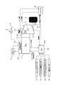
- FIG. 1 is a system diagram showing the configuration of an automatic engine control apparatus for a vehicle according to a first embodiment.
- FIG. 2 is a flowchart showing an engine automatic stop / restart control process of the first embodiment.
- FIG. 3 is a time chart showing an operation of setting processing of the coast stop permission threshold value during coast driving of the first embodiment.
- FIG. 1 is a system diagram showing the configuration of an automatic engine control apparatus for a vehicle according to a first embodiment.
- a torque converter 2 is provided on the output side of an engine 1 which is an internal combustion engine.
- a belt-type continuously variable transmission 3 is connected to the output side of the torque converter 2.
- the rotational drive force output from the engine 1 is input to the belt-type continuously variable transmission 3 via the torque converter 2 and is transmitted to the drive wheels 4 after being shifted at a desired gear ratio.
- the engine 1 is provided with a starter 1a for starting the engine and an alternator 1b for generating electricity.
- the starter 1a includes a starter motor.
- the starting device 1a drives the starter motor using the power supplied from the on-board battery 1c based on the engine start command, and performs engine cranking. Also, fuel is injected, and then the starter motor is stopped when the engine 1 becomes capable of self-sustaining rotation.
- the alternator 1 b generates electric power by being rotationally driven by the engine 1 and supplies the generated electric power to the on-vehicle battery 1 c and the like.
- the torque converter 2 performs torque amplification at low vehicle speeds.
- the torque converter 2 also has a lockup clutch, and at a predetermined vehicle speed CSVSP1 (for example, about 14 km / h) or more, the lockup clutch is engaged and the output shaft of the engine 1 and the belt type continuously variable transmission 3 Restrict relative rotation with the input shaft of
- the belt-type continuously variable transmission 3 is composed of a start clutch, a primary pulley and a secondary pulley, and a belt stretched around these pulleys, and achieves desired gear ratio by changing the pulley groove width by hydraulic control. .
- an oil pump 30 driven by the engine 1 is provided in the belt type continuously variable transmission 3. When the engine is operating, this oil pump 30 is used as a hydraulic pressure source to supply converter pressure and lockup clutch pressure of the torque converter 2 and also to supply pulley pressure and clutch engagement pressure of the belt type continuously variable transmission 3.
- the belt type continuously variable transmission 3 (CVT) is provided with the electric oil pump 31 separately from the oil pump 30, and when the oil pressure can not be supplied by the oil pump 30 due to the automatic engine stop, the electric oil pump 31 operates to supply necessary hydraulic pressure to each actuator. Therefore, even when the engine is stopped, it is possible to compensate for the hydraulic oil leak and maintain the clutch engagement pressure.
- a master back 5 is provided.
- the master back 5 boosts the brake operation force using the intake negative pressure of the engine 1.
- the engine control unit 10 controls the operation state of the engine 1.
- the engine control unit 10 includes a brake signal from the brake switch 11 that outputs an ON signal when the driver operates the brake pedal, and an accelerator signal from the accelerator pedal opening degree sensor 12 that detects the driver's accelerator pedal operation amount.
- the negative pressure signal from the negative pressure sensor 15 that detects the negative pressure in the master back 5, the CVT state signal from the CVT control unit 20 described later, and the engine Signals such as water temperature, crank angle, engine speed, etc. are input.
- the engine control unit 10 starts or automatically stops the engine 1 based on the various signals.
- the driver's braking operation is performed by detecting the brake pedal operation amount using a sensor that detects the brake pedal stroke amount and the brake pedal depression force or a sensor that detects the wheel cylinder pressure.
- the intention may be detected, and the invention is not limited to the master cylinder pressure sensor 13.
- the CVT control unit 20 transmits and receives signals of the engine operating state and the CVT state with the engine control unit 10, and controls the transmission ratio of the belt type continuously variable transmission 3 and the like based on these signals. Specifically, when the travel range is selected, the start clutch is engaged, and the transmission ratio is determined from the transmission ratio map based on the accelerator pedal position and the vehicle speed, and each pulley pressure is controlled.
- the lockup clutch is released when the vehicle speed is less than the predetermined vehicle speed CSVSP1, but when the vehicle speed is equal to or higher than the predetermined vehicle speed CSVSP1, the lockup clutch is engaged to directly connect the engine 1 and the belt type continuously variable transmission 3
- the electric oil pump 31 is operated to secure the necessary oil pressure.
- the automatic engine control apparatus (engine control unit 10) of the vehicle according to the first embodiment performs engine idling when a predetermined condition (various conditions such as the brake pedal 6 is sufficiently depressed) is satisfied when the vehicle is stopped. Stop and perform so-called idling stop control. In addition, since what is necessary is just to implement a known structure suitably about idling stop control, detailed description is abbreviate
- coasting state including the state in which the brake pedal is operated
- the deceleration fuel cut control During the deceleration fuel cut control, the fuel injection is stopped, but the coasting torque transmitted from the drive wheel 4 maintains the engine speed via the lockup clutch. However, since the lockup clutch is released when the vehicle speed is reduced to the predetermined vehicle speed CSVSP1, the engine 1 is stopped if fuel is not injected. Therefore, conventionally, the deceleration fuel cut control is stopped at the timing at which the lockup clutch is released, fuel injection is resumed, engine independent rotation is maintained, and after the vehicle completely stops, engine idling is stopped. It was like that.
- fuel consumption can be improved if it is possible to further suppress fuel at the time of resumption of fuel injection in the process of once resuming fuel injection and stopping the engine again from the traveling state where fuel injection has been stopped in this way. It becomes. Therefore, in the coast stop control of the first embodiment, when the predetermined condition is satisfied, the engine 1 is kept stopped without resuming the fuel injection (without performing the fuel injection etc.), and after the vehicle is stopped It is possible to shift to idling stop control as it is.
- One of the conditions for performing coast stop control is that the driver's brake pedal operation amount is equal to or greater than a predetermined value.
- the reason for setting the amount of brake pedal operation as one of the conditions is that the start or stop (stop) of the coast stop control should be performed based on the driver's braking intention.
- Start stop control After the start of coast stop control, when the brake pedal operation amount decreases and falls below a predetermined value, the driver's non-braking intention (intention to continue traveling) can be recognized, so the engine 1 being stopped is restarted to start coast stop. End (stop) control.
- the negative pressure in the master back 5 falls below a predetermined value, as a condition for performing engine restart (ends coast stop control) while traveling. That is, even if the vehicle speed is less than the predetermined vehicle speed CSVSP1 and the brake pedal operation amount is equal to or more than the predetermined value, when the negative pressure falls below the predetermined value, the stopped engine 1 is restarted to terminate coast stop control Discontinue.
- the reason for using negative pressure as the condition for restarting the engine 1 is as follows.
- the brake operating force decreases when the negative pressure of the master back 5 disappears due to the engine stop.
- the engine restart determination threshold (negative pressure threshold THNP for prohibiting coast stop control) is set in consideration of the above circumstances, and the engine 1 is restarted when the negative pressure becomes lower than the negative pressure threshold THNP.
- FIG. 2 is a flowchart showing an engine automatic stop / restart control process executed by the engine control unit 10 according to the first embodiment.
- step S1 vehicle speed VSP, deceleration DVSP, brake pedal operation amount (master cylinder pressure) BRKQ, brake pedal operation amount BRKQ threshold value for permitting idling stop control (IS operation amount threshold value THQIS) and negative pressure BRKNP threshold value (IS)
- the negative pressure threshold THNPIS), the threshold of the brake pedal operation amount BRKQ for permitting coast stop control (CS operating amount threshold THQCS), and the negative pressure BRKNP threshold (CS negative pressure threshold THNPCS) are read, and the process proceeds to step S2.
- the vehicle speed VSP may be an average value of the wheel speeds detected by the wheel speed sensor 14 or may be an average value of the driven wheel speeds and is not particularly limited.
- the IS operation amount threshold THQIS of the brake pedal operation amount BRKQ is set to a value larger than the CS operation amount threshold THQCS. This is because creep torque is output when the engine is started in the vehicle stop state where idling stop is performed, but in a state where the braking force by the brake is low, the creep torque may cause the vehicle to move inadvertently. is there.
- the state in which the coast stop is performed is during deceleration of the vehicle (that is, while traveling), and in this state, it is an aim to improve fuel efficiency by stopping the engine as much as possible. Even if the engine 1 restarts before the vehicle is stopped, it is also because the driver is less likely to feel a jumping out due to the creep torque if the vehicle is traveling.
- the CS negative pressure threshold THNPCS of the negative pressure threshold THNP is a range in which changes in deceleration (braking force) due to the negative pressure difference between the CS negative pressure threshold THNPCS and the negative pressure after engine restart do not give the driver discomfort Size).
- the CS negative pressure threshold THNPCS is set to a value larger than the IS negative pressure threshold THNPIS. This is because the coast stop is performed when the vehicle is traveling, and when the engine 1 is restarted with no negative pressure, a negative pressure is suddenly generated to boost the brake operating force, and thus the braking force This is because the deceleration becomes large rapidly.
- the vehicle is in a stopped state, and even if the engine 1 is restarted with no negative pressure, the deceleration does not increase. Further, in terms of improvement of fuel consumption, it is preferable to stop the engine 1 as much as possible. As a result, during coast stop control, while suppressing an increase in rapid deceleration due to the occurrence of negative pressure suddenly during traveling, the idling time of the engine 1 is secured during idling stop control to ensure fuel economy. It is improving.
- step S2 it is determined whether the vehicle speed VSP is larger than a predetermined value VSP0 representing a vehicle stop state.
- a predetermined value VSP0 representing a vehicle stop state.
- the process proceeds to step S3. Otherwise, the process proceeds to step S14.
- the predetermined value VSP0 may be zero, or may be an extremely low vehicle speed region of about 1 to 2 km / h, as long as it can be determined that the vehicle substantially stops. Note that other conditions and the like that do not appear in this flowchart may be additionally set as appropriate.
- step S3 it is determined whether the coast stop control permission condition is satisfied, specifically, whether the coasting state (accelerator pedal operation amount is zero) and the brake pedal 6 is operated. If the permission condition of the coast stop control is satisfied, the process proceeds to step S4. Otherwise, the process proceeds to step S20, and the engine operating state is continued.
- step S4 it is determined whether the vehicle speed VSP is less than a predetermined vehicle speed CSVSP1 for permitting engine stop. If the vehicle speed is lower than the predetermined vehicle speed CSVSP1, the process proceeds to step S5. Otherwise, the process proceeds to step S20, and the engine operating state is continued.
- step S5 it is determined whether the vehicle speed VSP is equal to or higher than a predetermined vehicle speed CSVSP2. If the vehicle speed is equal to or higher than the predetermined vehicle speed CSVSP2, the process proceeds to step S6. Otherwise, the process proceeds to step S10.
- step S6 it is determined whether the brake pedal operation amount BRKQ exceeds the CS operation amount threshold THQCS. If the brake pedal operation amount BRKQ exceeds the CS operation amount threshold THQCS, the process proceeds to step S7. Otherwise, the process proceeds to step S9 to continue the engine start or the driving state.
- step S7 it is determined whether the negative pressure BRKNP exceeds the CS negative pressure threshold THNPCS.
- the process proceeds to step S8, and the engine 1 is stopped. Otherwise, the process proceeds to step S9 to continue the engine start or the operating state.
- step S10 it is determined whether the brake pedal operation amount BRKQ exceeds the IS operation amount threshold THQCS.
- the process proceeds to step S11, and otherwise proceeds to step S13 to continue the engine start or the operation state.
- step S11 it is determined whether the negative pressure BRKNP exceeds the IS negative pressure threshold THNPIS. If the negative pressure BRKNP exceeds the IS negative pressure threshold THNPIS, the process proceeds to step S12, and the engine 1 is stopped. Otherwise, the process proceeds to step S13 to continue the engine start or operating condition.
- step S14 it is determined whether the idle stop control permission condition is satisfied, specifically, whether the brake pedal 6 is operated, whether the temperature of the engine 1 is equal to or higher than a predetermined value, and the oil temperature is predetermined. It is determined whether or not it is a value or more.
- the process proceeds to step S15. Otherwise, the process proceeds to step S20, and the engine operating state is continued.
- step S15 it is determined whether the brake pedal operation amount BRKQ exceeds the IS operation amount threshold THQIS. If the brake pedal operation amount BRKQ exceeds the IS operation amount threshold THQIS, the process proceeds to step S16. Otherwise, the process proceeds to step S18 to continue engine start or operation.
- step S16 it is determined whether the negative pressure BRKNP exceeds the IS negative pressure threshold THNPIS.
- the process proceeds to step S17 to stop the engine 1, and otherwise, the process proceeds to step S18 to continue the engine start or the operating state.
- FIG. 3 is a time chart showing the operation of the process of setting the negative pressure threshold THNP during coasting of the first embodiment.
- FIG. 3 shows changes in the brake pedal operation amount BRKQ, the negative pressure BRKNP, the engine rotational speed Ne, the vehicle speed VSP, and the acceleration DVSP in order from the top.
- the traveling state (precondition) at the first time of this time chart is a coasting state in which the driver releases his / her foot from the accelerator pedal while traveling.
- the vehicle speed VSP is equal to or higher than a predetermined vehicle speed CSVSP1. Accordingly, in the control processing of FIG. 2, the flow proceeds to step S1 ⁇ S2 ⁇ S3 ⁇ S4 ⁇ S20, and the engine 1 continues the operating state. In addition, the driver's brake pedal operation amount BRKQ gradually decreases.
- the vehicle speed VSP becomes less than the predetermined vehicle speed CSVSP1
- the brake pedal operation amount BRKQ exceeds the CS operation amount threshold THQCS
- the negative pressure BRKNP exceeds the CS negative pressure threshold THNPCS. Accordingly, in the control process of FIG. 2, the flow proceeds to step S1 ⁇ S2 ⁇ S3 ⁇ S4 ⁇ S5 ⁇ S6 ⁇ S7 ⁇ S8, and the engine 1 is stopped. After time t1 at which the engine stop is started, the engine speed decreases rapidly toward zero.
- the negative pressure BRKNP becomes equal to or lower than the CS negative pressure threshold THNPCS. Accordingly, in the control process of FIG. 2, the process proceeds to step S1 ⁇ S2 ⁇ S3 ⁇ S4 ⁇ S5 ⁇ S6 ⁇ S7 ⁇ S9, and the engine 1 is restarted. Since the negative pressure BRKNP is secured even before time t2, the brake operating force is sufficiently boosted. Therefore, even if the engine 1 is restarted, the deceleration does not rapidly increase without the brake operation force rapidly increasing.
- the vehicle speed VSP becomes less than the predetermined vehicle speed CSVSP2, and the negative pressure threshold THNP switches from the CS negative pressure threshold THNPCS to the IS negative pressure threshold THNPIS.
- the negative pressure BRKNP exceeds the IS negative pressure threshold THNPIS. Accordingly, in the control process of FIG. 2, the process proceeds to step S1 ⁇ S2 ⁇ S3 ⁇ S4 ⁇ S5 ⁇ S10 ⁇ S11 ⁇ S12, and the engine 1 is stopped. After time t3 when the engine stop is started, the engine speed rapidly decreases toward zero.
- the vehicle speed VSP becomes zero, and the manipulation amount threshold THQ switches from the CS manipulation amount threshold THQCS to the IS manipulation amount threshold THQIS.
- the brake pedal operation amount BRKQ exceeds the IS operation amount threshold THQIS, and the negative pressure BRKNP exceeds the IS negative pressure threshold THNPIS. Accordingly, in the control process of FIG. 2, the process proceeds to step S1 ⁇ S2 ⁇ S14 ⁇ S15 ⁇ S16 ⁇ S17, and the engine stop is continued.
- the operation up to time t2 is the same as in the first embodiment.
- the negative pressure BRKNP exceeds the IS negative pressure threshold THNPIS. Therefore, the engine stop will be continued.
- the negative pressure BRKNP becomes equal to or lower than the IS negative pressure threshold THNPIS, and the engine 1 is restarted.
- the brake operating force is not sufficiently boosted because the negative pressure BRKNP is decreasing. Therefore, as the engine 1 restarts, a negative pressure in the master back 5 is generated, and the brake operation force rapidly increases, so the deceleration rapidly increases and a shock occurs.
- the CS negative pressure threshold THNPCS is set larger than the IS negative pressure threshold THNPIS. Therefore, the engine 1 can be started in a state where the negative pressure BRKNP is sufficient, and even if the engine 1 is restarted, the rapid increase in deceleration without suppressing the sharp increase in the brake operation force can be suppressed. it can.
- the engine 1 can be stopped immediately after the vehicle stops to start idling stop.
- Master cylinder pressure sensor 13 for detecting the brake pedal operation amount BRKQ of the driver and master back 5 for increasing the brake operation force using the intake negative pressure of the engine 1 (negative Pressure boosting means), a negative pressure sensor 15 (negative pressure detection means) for detecting the negative pressure BRKNP of the master back 5, and the detected brake pedal operation amount BRKQ during coasting travel is CS operation amount threshold THQCS
- the engine 1 is stopped when the operation amount threshold) or more, and the engine 1 is restarted when the negative pressure BRKNP detected after the engine stops falls below the CS negative pressure threshold THNPCS (first negative pressure threshold)
- a control unit 10 coast stop control means
- the engine 1 can be started before the negative pressure BRKNP disappears, and even if the engine 1 is restarted, it is possible to suppress an abrupt increase in deceleration without the brake operating force rapidly increasing.
- the engine control unit 10 detects that the detected brake pedal operation amount BRKQ is greater than the IS operation amount threshold THQIS (second operation amount threshold) while the vehicle is stopped.
- THQIS second operation amount threshold
- the engine is restarted and the CS manipulated variable threshold THQCS is IS negative pressure threshold Set to a value higher than THNPIS.
- the engine 1 can be started in a state where the negative pressure BRKNP is sufficient, and even if the engine 1 is restarted, the rapid increase in deceleration without the sharp increase in the brake operating force is suppressed. Can.
- the engine control unit 10 restarts the engine when the negative pressure BRKNP detected after stopping the engine during coasting travel falls below the IS negative pressure threshold THNPIS.
- the engine 1 can be stopped immediately after the vehicle stops to start idling stop.
- the present invention has been described above based on the first embodiment, the present invention is not limited to the above-described embodiment, and other configurations are included in the present invention.
- adopted the belt type continuously variable transmission was shown in Example 1, the structure provided with the other stepped automatic transmission, the manual transmission, etc. may be sufficient.
- the torque converter is provided is shown, the invention can also be applied to a vehicle not provided with the torque converter. In these cases, not the predetermined vehicle speed CSVSP1 but other parameters (combination of vehicle speed and gear ratio and engine speed) that indicate whether or not the engine self-sustaining rotation can be maintained as parameters of conditions for permitting coast stop control (engine automatic stop) Can be used.
Landscapes
- Engineering & Computer Science (AREA)
- Mechanical Engineering (AREA)
- Transportation (AREA)
- Automation & Control Theory (AREA)
- Chemical & Material Sciences (AREA)
- Combustion & Propulsion (AREA)
- General Engineering & Computer Science (AREA)
- Control Of Vehicle Engines Or Engines For Specific Uses (AREA)
- Output Control And Ontrol Of Special Type Engine (AREA)
Abstract
L'invention porte sur un dispositif de commande automatique de moteur de véhicule. Lors de la marche sur l'erre, le dispositif de commande automatique de moteur de véhicule arrête le moteur si un degré de manœuvre de la pédale de frein détecté atteint ou excède un premier seuil de degré de manœuvre et, après avoir arrêté le moteur, redémarre le moteur lorsqu'une pression négative détectée tombe au-dessous d'un premier seuil de pression négative.
Priority Applications (3)
| Application Number | Priority Date | Filing Date | Title |
|---|---|---|---|
| US14/362,700 US10619614B2 (en) | 2011-12-06 | 2012-11-16 | Vehicle engine automatic control device and vehicle engine automatic control method |
| EP12856193.3A EP2789834B1 (fr) | 2011-12-06 | 2012-11-16 | Dispositif de commande automatique de moteur de véhicule |
| CN201280059841.9A CN103998751B (zh) | 2011-12-06 | 2012-11-16 | 车辆的发动机自动控制装置 |
Applications Claiming Priority (2)
| Application Number | Priority Date | Filing Date | Title |
|---|---|---|---|
| JP2011-266602 | 2011-12-06 | ||
| JP2011266602A JP5870660B2 (ja) | 2011-12-06 | 2011-12-06 | 車両のエンジン自動制御装置 |
Publications (1)
| Publication Number | Publication Date |
|---|---|
| WO2013084697A1 true WO2013084697A1 (fr) | 2013-06-13 |
Family
ID=48574075
Family Applications (1)
| Application Number | Title | Priority Date | Filing Date |
|---|---|---|---|
| PCT/JP2012/079811 WO2013084697A1 (fr) | 2011-12-06 | 2012-11-16 | Dispositif de commande automatique de moteur de véhicule |
Country Status (5)
| Country | Link |
|---|---|
| US (1) | US10619614B2 (fr) |
| EP (1) | EP2789834B1 (fr) |
| JP (1) | JP5870660B2 (fr) |
| CN (1) | CN103998751B (fr) |
| WO (1) | WO2013084697A1 (fr) |
Cited By (3)
| Publication number | Priority date | Publication date | Assignee | Title |
|---|---|---|---|---|
| US9951738B2 (en) | 2014-03-11 | 2018-04-24 | Voyomotive, Llc | Method of signaling an engine stop or start request |
| CN109969184A (zh) * | 2017-12-15 | 2019-07-05 | Zf 腓德烈斯哈芬股份公司 | 用于运行机动车的驱动系的方法 |
| US11001263B2 (en) | 2018-03-07 | 2021-05-11 | Toyota Jidosha Kabushiki Kaisha | Braking force control system, device, and method |
Families Citing this family (12)
| Publication number | Priority date | Publication date | Assignee | Title |
|---|---|---|---|---|
| JP6493953B2 (ja) * | 2014-09-05 | 2019-04-03 | ボッシュ株式会社 | 還元剤噴射装置の制御装置及び制御方法並びに還元剤噴射装置 |
| DE102015202093A1 (de) | 2015-02-05 | 2016-08-11 | Bayerische Motoren Werke Aktiengesellschaft | Steuereinheit und Verfahren zum Verhindern einer ungewollten Fahrzeugbewegung |
| JP6565699B2 (ja) * | 2015-02-25 | 2019-08-28 | 株式会社デンソー | 車両制御装置 |
| JP6407080B2 (ja) * | 2015-03-26 | 2018-10-17 | ジヤトコ株式会社 | 車両用発進制御装置 |
| JP6544216B2 (ja) * | 2015-11-20 | 2019-07-17 | スズキ株式会社 | ハイブリッド車両の制御装置 |
| DE102015224109A1 (de) * | 2015-12-02 | 2017-06-08 | Bayerische Motoren Werke Aktiengesellschaft | Start-Stopp-Einrichtung zum Einleiten eines automatischen Abschaltvorgangs einer Antriebsmaschine eines Kraftfahrzeugs |
| DE102016224931A1 (de) * | 2016-12-14 | 2018-06-14 | Volkswagen Aktiengesellschaft | Verfahren zur Steuerung und/oder Regelung eines Antriebsstrangs eines Kraftfahrzeugs |
| FR3063957B1 (fr) * | 2017-03-15 | 2019-04-05 | Renault S.A.S. | Procede de controle de fonctions automatiques d'un vehicule automobile |
| US20180290638A1 (en) * | 2017-04-11 | 2018-10-11 | Delphi Technologies, Inc. | Automated vehicle open-loop brake control system |
| KR20190073182A (ko) * | 2017-12-18 | 2019-06-26 | 현대자동차주식회사 | Isg 기능을 포함하는 차량의 제어 방법 및 그 제어 장치 |
| GB2579178B (en) * | 2018-11-21 | 2021-04-14 | Jaguar Land Rover Ltd | Vehicle control method |
| JP6936275B2 (ja) * | 2019-04-22 | 2021-09-15 | 本田技研工業株式会社 | 車両 |
Citations (9)
| Publication number | Priority date | Publication date | Assignee | Title |
|---|---|---|---|---|
| JP2000310133A (ja) * | 1999-04-26 | 2000-11-07 | Toyota Motor Corp | エンジンの自動停止始動装置 |
| JP2002195068A (ja) * | 2000-12-22 | 2002-07-10 | Toyota Motor Corp | 車載内燃機関の制御装置 |
| JP2002221059A (ja) * | 2001-01-26 | 2002-08-09 | Denso Corp | エンジン制御装置 |
| JP2004084593A (ja) * | 2002-08-28 | 2004-03-18 | Nissan Motor Co Ltd | エンジンのアイドルストップ制御装置 |
| JP4374805B2 (ja) | 2001-07-24 | 2009-12-02 | 株式会社デンソー | エンジン自動車の停止再始動装置 |
| JP2010163898A (ja) * | 2009-01-13 | 2010-07-29 | Nissan Motor Co Ltd | 内燃機関の始動装置 |
| JP2011127439A (ja) * | 2009-12-15 | 2011-06-30 | Denso Corp | 内燃機関の制御装置 |
| WO2011135725A1 (fr) * | 2010-04-30 | 2011-11-03 | トヨタ自動車株式会社 | Système de commande de véhicule |
| JP2012077647A (ja) * | 2010-09-30 | 2012-04-19 | Toyota Motor Corp | 車両制御装置 |
Family Cites Families (10)
| Publication number | Priority date | Publication date | Assignee | Title |
|---|---|---|---|---|
| DE69919648T2 (de) | 1998-09-28 | 2005-09-08 | Toyota Jidosha K.K., Toyota | Start-stopvorrichtung für Kraftfahrzeugmotor |
| JP2001012272A (ja) * | 1999-06-29 | 2001-01-16 | Toyota Motor Corp | 内燃機関の自動停止・始動装置 |
| JP2001055941A (ja) * | 1999-08-16 | 2001-02-27 | Honda Motor Co Ltd | エンジン自動始動停止制御装置 |
| US6624527B1 (en) * | 2000-09-15 | 2003-09-23 | Ford Motor Company | Method and apparatus for reducing engine cycling in hybrid electric vehicle |
| US6664651B1 (en) * | 2000-11-14 | 2003-12-16 | Ford Motor Company | Engine on idle arbitration for a hybrid electric vehicle |
| DE60228771D1 (de) | 2001-01-26 | 2008-10-16 | Denso Corp | Kraftwerksteuerapparat |
| JP4552365B2 (ja) * | 2001-06-27 | 2010-09-29 | 株式会社デンソー | エンジン自動停止再始動装置 |
| DE60307013T2 (de) * | 2002-10-28 | 2006-11-23 | Nissan Motor Co., Ltd., Yokohama | Motorsteuerung für ein Fahrzeug mit elektronischem Schlüssel |
| JP5241021B2 (ja) * | 2009-03-24 | 2013-07-17 | 本田技研工業株式会社 | エンジン始動制御装置 |
| DE102009027337B4 (de) * | 2009-06-30 | 2017-03-23 | Ford Global Technologies, Llc | Verfahren zum Schätzen des in einem Kraftfahrzeug-Bremskraftverstärker herrschenden Unterdrucks sowie Stopp-Start-Steuereinrichtung |
-
2011
- 2011-12-06 JP JP2011266602A patent/JP5870660B2/ja active Active
-
2012
- 2012-11-16 EP EP12856193.3A patent/EP2789834B1/fr active Active
- 2012-11-16 WO PCT/JP2012/079811 patent/WO2013084697A1/fr active Application Filing
- 2012-11-16 CN CN201280059841.9A patent/CN103998751B/zh active Active
- 2012-11-16 US US14/362,700 patent/US10619614B2/en active Active
Patent Citations (9)
| Publication number | Priority date | Publication date | Assignee | Title |
|---|---|---|---|---|
| JP2000310133A (ja) * | 1999-04-26 | 2000-11-07 | Toyota Motor Corp | エンジンの自動停止始動装置 |
| JP2002195068A (ja) * | 2000-12-22 | 2002-07-10 | Toyota Motor Corp | 車載内燃機関の制御装置 |
| JP2002221059A (ja) * | 2001-01-26 | 2002-08-09 | Denso Corp | エンジン制御装置 |
| JP4374805B2 (ja) | 2001-07-24 | 2009-12-02 | 株式会社デンソー | エンジン自動車の停止再始動装置 |
| JP2004084593A (ja) * | 2002-08-28 | 2004-03-18 | Nissan Motor Co Ltd | エンジンのアイドルストップ制御装置 |
| JP2010163898A (ja) * | 2009-01-13 | 2010-07-29 | Nissan Motor Co Ltd | 内燃機関の始動装置 |
| JP2011127439A (ja) * | 2009-12-15 | 2011-06-30 | Denso Corp | 内燃機関の制御装置 |
| WO2011135725A1 (fr) * | 2010-04-30 | 2011-11-03 | トヨタ自動車株式会社 | Système de commande de véhicule |
| JP2012077647A (ja) * | 2010-09-30 | 2012-04-19 | Toyota Motor Corp | 車両制御装置 |
Non-Patent Citations (1)
| Title |
|---|
| See also references of EP2789834A4 |
Cited By (6)
| Publication number | Priority date | Publication date | Assignee | Title |
|---|---|---|---|---|
| US9951738B2 (en) | 2014-03-11 | 2018-04-24 | Voyomotive, Llc | Method of signaling an engine stop or start request |
| CN109969184A (zh) * | 2017-12-15 | 2019-07-05 | Zf 腓德烈斯哈芬股份公司 | 用于运行机动车的驱动系的方法 |
| CN109969184B (zh) * | 2017-12-15 | 2024-05-07 | Zf腓德烈斯哈芬股份公司 | 用于运行机动车的驱动系的方法 |
| US11001263B2 (en) | 2018-03-07 | 2021-05-11 | Toyota Jidosha Kabushiki Kaisha | Braking force control system, device, and method |
| US11697415B2 (en) | 2018-03-07 | 2023-07-11 | Toyota Jidosha Kabushiki Kaisha | Braking force control system, device, and method |
| USRE49777E1 (en) | 2018-03-07 | 2024-01-02 | Toyota Jidosha Kabushiki Kaisha | Braking force control system, device, and method |
Also Published As
| Publication number | Publication date |
|---|---|
| JP5870660B2 (ja) | 2016-03-01 |
| EP2789834B1 (fr) | 2017-03-01 |
| EP2789834A4 (fr) | 2016-03-30 |
| US10619614B2 (en) | 2020-04-14 |
| CN103998751B (zh) | 2016-10-12 |
| JP2013119775A (ja) | 2013-06-17 |
| CN103998751A (zh) | 2014-08-20 |
| EP2789834A1 (fr) | 2014-10-15 |
| US20140336907A1 (en) | 2014-11-13 |
Similar Documents
| Publication | Publication Date | Title |
|---|---|---|
| WO2013084697A1 (fr) | Dispositif de commande automatique de moteur de véhicule | |
| US9470156B2 (en) | Vehicle engine automatic control device and vehicle engine automatic control method | |
| JP3885449B2 (ja) | 車両のエンジン自動停止再始動装置 | |
| US9562480B2 (en) | Automatic engine-stop control device for vehicle | |
| JP6369549B2 (ja) | 車両の制御装置および車両の制御方法 | |
| JP5834844B2 (ja) | 車両のエンジン自動制御装置 | |
| JP2007331533A (ja) | 車両用制御装置 | |
| JP6241424B2 (ja) | 車両制御装置 | |
| JP2011179597A (ja) | 車両駆動システムの制御装置 | |
| JP2014134275A (ja) | 車両の制御装置 | |
| WO2017183519A1 (fr) | Dispositif de commande de véhicule | |
| WO2017203874A1 (fr) | Dispositif de commande et procédé de commande pour véhicule comprenant une transmission à variation continue | |
| WO2013084690A1 (fr) | Dispositif de commande automatique de moteur de véhicule | |
| US10501083B2 (en) | Vehicle control device and vehicle control method | |
| JP2010071205A (ja) | 内燃機関の制御装置 | |
| JP5936572B2 (ja) | 車両制御装置 | |
| JPWO2019069345A1 (ja) | 内燃機関の制御方法及び内燃機関の制御装置 | |
| WO2013084691A1 (fr) | Dispositif de commande automatique de moteur de véhicule | |
| WO2019069344A1 (fr) | Procédé et dispositif de commande de véhicule | |
| JP6481536B2 (ja) | エンジン制御方法及びエンジン制御装置 | |
| WO2019069444A1 (fr) | Procédé permettant de commander un moteur à combustion interne et dispositif permettant de commander un moteur à combustion interne | |
| JP2018127103A (ja) | 車両及び車両の制御方法 | |
| JP2018115703A (ja) | 車両及び車両の制御方法 | |
| JP2015077860A (ja) | ハイブリッド車両の制御装置 |
Legal Events
| Date | Code | Title | Description |
|---|---|---|---|
| 121 | Ep: the epo has been informed by wipo that ep was designated in this application |
Ref document number: 12856193 Country of ref document: EP Kind code of ref document: A1 |
|
| WWE | Wipo information: entry into national phase |
Ref document number: 14362700 Country of ref document: US |
|
| NENP | Non-entry into the national phase |
Ref country code: DE |
|
| REEP | Request for entry into the european phase |
Ref document number: 2012856193 Country of ref document: EP |
|
| WWE | Wipo information: entry into national phase |
Ref document number: 2012856193 Country of ref document: EP |