WO2013084697A1 - 車両のエンジン自動制御装置 - Google Patents
車両のエンジン自動制御装置 Download PDFInfo
- Publication number
- WO2013084697A1 WO2013084697A1 PCT/JP2012/079811 JP2012079811W WO2013084697A1 WO 2013084697 A1 WO2013084697 A1 WO 2013084697A1 JP 2012079811 W JP2012079811 W JP 2012079811W WO 2013084697 A1 WO2013084697 A1 WO 2013084697A1
- Authority
- WO
- WIPO (PCT)
- Prior art keywords
- engine
- negative pressure
- threshold
- operation amount
- vehicle
- Prior art date
Links
Images


Classifications
-
- F—MECHANICAL ENGINEERING; LIGHTING; HEATING; WEAPONS; BLASTING
- F02—COMBUSTION ENGINES; HOT-GAS OR COMBUSTION-PRODUCT ENGINE PLANTS
- F02N—STARTING OF COMBUSTION ENGINES; STARTING AIDS FOR SUCH ENGINES, NOT OTHERWISE PROVIDED FOR
- F02N11/00—Starting of engines by means of electric motors
- F02N11/08—Circuits or control means specially adapted for starting of engines
- F02N11/0814—Circuits or control means specially adapted for starting of engines comprising means for controlling automatic idle-start-stop
- F02N11/0818—Conditions for starting or stopping the engine or for deactivating the idle-start-stop mode
- F02N11/0833—Vehicle conditions
- F02N11/084—State of vehicle accessories, e.g. air condition or power steering
-
- B—PERFORMING OPERATIONS; TRANSPORTING
- B60—VEHICLES IN GENERAL
- B60T—VEHICLE BRAKE CONTROL SYSTEMS OR PARTS THEREOF; BRAKE CONTROL SYSTEMS OR PARTS THEREOF, IN GENERAL; ARRANGEMENT OF BRAKING ELEMENTS ON VEHICLES IN GENERAL; PORTABLE DEVICES FOR PREVENTING UNWANTED MOVEMENT OF VEHICLES; VEHICLE MODIFICATIONS TO FACILITATE COOLING OF BRAKES
- B60T17/00—Component parts, details, or accessories of power brake systems not covered by groups B60T8/00, B60T13/00 or B60T15/00, or presenting other characteristic features
-
- B—PERFORMING OPERATIONS; TRANSPORTING
- B60—VEHICLES IN GENERAL
- B60T—VEHICLE BRAKE CONTROL SYSTEMS OR PARTS THEREOF; BRAKE CONTROL SYSTEMS OR PARTS THEREOF, IN GENERAL; ARRANGEMENT OF BRAKING ELEMENTS ON VEHICLES IN GENERAL; PORTABLE DEVICES FOR PREVENTING UNWANTED MOVEMENT OF VEHICLES; VEHICLE MODIFICATIONS TO FACILITATE COOLING OF BRAKES
- B60T7/00—Brake-action initiating means
- B60T7/02—Brake-action initiating means for personal initiation
- B60T7/04—Brake-action initiating means for personal initiation foot actuated
- B60T7/042—Brake-action initiating means for personal initiation foot actuated by electrical means, e.g. using travel or force sensors
-
- B—PERFORMING OPERATIONS; TRANSPORTING
- B60—VEHICLES IN GENERAL
- B60W—CONJOINT CONTROL OF VEHICLE SUB-UNITS OF DIFFERENT TYPE OR DIFFERENT FUNCTION; CONTROL SYSTEMS SPECIALLY ADAPTED FOR HYBRID VEHICLES; ROAD VEHICLE DRIVE CONTROL SYSTEMS FOR PURPOSES NOT RELATED TO THE CONTROL OF A PARTICULAR SUB-UNIT
- B60W30/00—Purposes of road vehicle drive control systems not related to the control of a particular sub-unit, e.g. of systems using conjoint control of vehicle sub-units, or advanced driver assistance systems for ensuring comfort, stability and safety or drive control systems for propelling or retarding the vehicle
- B60W30/18—Propelling the vehicle
- B60W30/18009—Propelling the vehicle related to particular drive situations
- B60W30/18018—Start-stop drive, e.g. in a traffic jam
-
- B—PERFORMING OPERATIONS; TRANSPORTING
- B60—VEHICLES IN GENERAL
- B60W—CONJOINT CONTROL OF VEHICLE SUB-UNITS OF DIFFERENT TYPE OR DIFFERENT FUNCTION; CONTROL SYSTEMS SPECIALLY ADAPTED FOR HYBRID VEHICLES; ROAD VEHICLE DRIVE CONTROL SYSTEMS FOR PURPOSES NOT RELATED TO THE CONTROL OF A PARTICULAR SUB-UNIT
- B60W30/00—Purposes of road vehicle drive control systems not related to the control of a particular sub-unit, e.g. of systems using conjoint control of vehicle sub-units, or advanced driver assistance systems for ensuring comfort, stability and safety or drive control systems for propelling or retarding the vehicle
- B60W30/18—Propelling the vehicle
- B60W30/18009—Propelling the vehicle related to particular drive situations
- B60W30/18063—Creeping
-
- B—PERFORMING OPERATIONS; TRANSPORTING
- B60—VEHICLES IN GENERAL
- B60W—CONJOINT CONTROL OF VEHICLE SUB-UNITS OF DIFFERENT TYPE OR DIFFERENT FUNCTION; CONTROL SYSTEMS SPECIALLY ADAPTED FOR HYBRID VEHICLES; ROAD VEHICLE DRIVE CONTROL SYSTEMS FOR PURPOSES NOT RELATED TO THE CONTROL OF A PARTICULAR SUB-UNIT
- B60W30/00—Purposes of road vehicle drive control systems not related to the control of a particular sub-unit, e.g. of systems using conjoint control of vehicle sub-units, or advanced driver assistance systems for ensuring comfort, stability and safety or drive control systems for propelling or retarding the vehicle
- B60W30/18—Propelling the vehicle
- B60W30/18009—Propelling the vehicle related to particular drive situations
- B60W30/18072—Coasting
-
- F—MECHANICAL ENGINEERING; LIGHTING; HEATING; WEAPONS; BLASTING
- F02—COMBUSTION ENGINES; HOT-GAS OR COMBUSTION-PRODUCT ENGINE PLANTS
- F02D—CONTROLLING COMBUSTION ENGINES
- F02D29/00—Controlling engines, such controlling being peculiar to the devices driven thereby, the devices being other than parts or accessories essential to engine operation, e.g. controlling of engines by signals external thereto
-
- B—PERFORMING OPERATIONS; TRANSPORTING
- B60—VEHICLES IN GENERAL
- B60W—CONJOINT CONTROL OF VEHICLE SUB-UNITS OF DIFFERENT TYPE OR DIFFERENT FUNCTION; CONTROL SYSTEMS SPECIALLY ADAPTED FOR HYBRID VEHICLES; ROAD VEHICLE DRIVE CONTROL SYSTEMS FOR PURPOSES NOT RELATED TO THE CONTROL OF A PARTICULAR SUB-UNIT
- B60W30/00—Purposes of road vehicle drive control systems not related to the control of a particular sub-unit, e.g. of systems using conjoint control of vehicle sub-units, or advanced driver assistance systems for ensuring comfort, stability and safety or drive control systems for propelling or retarding the vehicle
- B60W30/18—Propelling the vehicle
- B60W30/18009—Propelling the vehicle related to particular drive situations
- B60W30/18072—Coasting
- B60W2030/18081—With torque flow from driveshaft to engine, i.e. engine being driven by vehicle
-
- B—PERFORMING OPERATIONS; TRANSPORTING
- B60—VEHICLES IN GENERAL
- B60W—CONJOINT CONTROL OF VEHICLE SUB-UNITS OF DIFFERENT TYPE OR DIFFERENT FUNCTION; CONTROL SYSTEMS SPECIALLY ADAPTED FOR HYBRID VEHICLES; ROAD VEHICLE DRIVE CONTROL SYSTEMS FOR PURPOSES NOT RELATED TO THE CONTROL OF A PARTICULAR SUB-UNIT
- B60W30/00—Purposes of road vehicle drive control systems not related to the control of a particular sub-unit, e.g. of systems using conjoint control of vehicle sub-units, or advanced driver assistance systems for ensuring comfort, stability and safety or drive control systems for propelling or retarding the vehicle
- B60W30/18—Propelling the vehicle
- B60W30/18009—Propelling the vehicle related to particular drive situations
- B60W30/18072—Coasting
- B60W2030/1809—Without torque flow between driveshaft and engine, e.g. with clutch disengaged or transmission in neutral
-
- B—PERFORMING OPERATIONS; TRANSPORTING
- B60—VEHICLES IN GENERAL
- B60W—CONJOINT CONTROL OF VEHICLE SUB-UNITS OF DIFFERENT TYPE OR DIFFERENT FUNCTION; CONTROL SYSTEMS SPECIALLY ADAPTED FOR HYBRID VEHICLES; ROAD VEHICLE DRIVE CONTROL SYSTEMS FOR PURPOSES NOT RELATED TO THE CONTROL OF A PARTICULAR SUB-UNIT
- B60W2520/00—Input parameters relating to overall vehicle dynamics
- B60W2520/10—Longitudinal speed
-
- B—PERFORMING OPERATIONS; TRANSPORTING
- B60—VEHICLES IN GENERAL
- B60W—CONJOINT CONTROL OF VEHICLE SUB-UNITS OF DIFFERENT TYPE OR DIFFERENT FUNCTION; CONTROL SYSTEMS SPECIALLY ADAPTED FOR HYBRID VEHICLES; ROAD VEHICLE DRIVE CONTROL SYSTEMS FOR PURPOSES NOT RELATED TO THE CONTROL OF A PARTICULAR SUB-UNIT
- B60W2540/00—Input parameters relating to occupants
- B60W2540/12—Brake pedal position
-
- F—MECHANICAL ENGINEERING; LIGHTING; HEATING; WEAPONS; BLASTING
- F02—COMBUSTION ENGINES; HOT-GAS OR COMBUSTION-PRODUCT ENGINE PLANTS
- F02N—STARTING OF COMBUSTION ENGINES; STARTING AIDS FOR SUCH ENGINES, NOT OTHERWISE PROVIDED FOR
- F02N2200/00—Parameters used for control of starting apparatus
- F02N2200/08—Parameters used for control of starting apparatus said parameters being related to the vehicle or its components
- F02N2200/0801—Vehicle speed
-
- F—MECHANICAL ENGINEERING; LIGHTING; HEATING; WEAPONS; BLASTING
- F02—COMBUSTION ENGINES; HOT-GAS OR COMBUSTION-PRODUCT ENGINE PLANTS
- F02N—STARTING OF COMBUSTION ENGINES; STARTING AIDS FOR SUCH ENGINES, NOT OTHERWISE PROVIDED FOR
- F02N2200/00—Parameters used for control of starting apparatus
- F02N2200/08—Parameters used for control of starting apparatus said parameters being related to the vehicle or its components
- F02N2200/0807—Brake booster state
-
- F—MECHANICAL ENGINEERING; LIGHTING; HEATING; WEAPONS; BLASTING
- F02—COMBUSTION ENGINES; HOT-GAS OR COMBUSTION-PRODUCT ENGINE PLANTS
- F02N—STARTING OF COMBUSTION ENGINES; STARTING AIDS FOR SUCH ENGINES, NOT OTHERWISE PROVIDED FOR
- F02N2200/00—Parameters used for control of starting apparatus
- F02N2200/10—Parameters used for control of starting apparatus said parameters being related to driver demands or status
- F02N2200/101—Accelerator pedal position
-
- F—MECHANICAL ENGINEERING; LIGHTING; HEATING; WEAPONS; BLASTING
- F02—COMBUSTION ENGINES; HOT-GAS OR COMBUSTION-PRODUCT ENGINE PLANTS
- F02N—STARTING OF COMBUSTION ENGINES; STARTING AIDS FOR SUCH ENGINES, NOT OTHERWISE PROVIDED FOR
- F02N2200/00—Parameters used for control of starting apparatus
- F02N2200/10—Parameters used for control of starting apparatus said parameters being related to driver demands or status
- F02N2200/102—Brake pedal position
-
- Y—GENERAL TAGGING OF NEW TECHNOLOGICAL DEVELOPMENTS; GENERAL TAGGING OF CROSS-SECTIONAL TECHNOLOGIES SPANNING OVER SEVERAL SECTIONS OF THE IPC; TECHNICAL SUBJECTS COVERED BY FORMER USPC CROSS-REFERENCE ART COLLECTIONS [XRACs] AND DIGESTS
- Y02—TECHNOLOGIES OR APPLICATIONS FOR MITIGATION OR ADAPTATION AGAINST CLIMATE CHANGE
- Y02T—CLIMATE CHANGE MITIGATION TECHNOLOGIES RELATED TO TRANSPORTATION
- Y02T10/00—Road transport of goods or passengers
- Y02T10/10—Internal combustion engine [ICE] based vehicles
- Y02T10/40—Engine management systems
-
- Y—GENERAL TAGGING OF NEW TECHNOLOGICAL DEVELOPMENTS; GENERAL TAGGING OF CROSS-SECTIONAL TECHNOLOGIES SPANNING OVER SEVERAL SECTIONS OF THE IPC; TECHNICAL SUBJECTS COVERED BY FORMER USPC CROSS-REFERENCE ART COLLECTIONS [XRACs] AND DIGESTS
- Y02—TECHNOLOGIES OR APPLICATIONS FOR MITIGATION OR ADAPTATION AGAINST CLIMATE CHANGE
- Y02T—CLIMATE CHANGE MITIGATION TECHNOLOGIES RELATED TO TRANSPORTATION
- Y02T10/00—Road transport of goods or passengers
- Y02T10/60—Other road transportation technologies with climate change mitigation effect
Definitions
- the present invention relates to an automatic engine control device that automatically stops and restarts an engine while traveling.
- JP 4374805 B is disclosed as an automatic engine control device for a vehicle.
- the engine is stopped to improve fuel efficiency, and the brake pedal operation amount becomes equal to or less than the engine start determination threshold value. If it does, restart the engine.
- the present invention has been made in view of the above problems, and it is an object of the present invention to provide an automatic engine control device for a vehicle that can suppress the occurrence of rapid deceleration.
- the automatic control device for a vehicle stops the engine when the detected brake pedal operation amount is equal to or more than the first operation amount threshold during coasting, and the negative pressure detected after the engine is stopped is the first. The engine is restarted when the negative pressure threshold is exceeded.
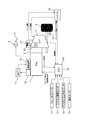
- FIG. 1 is a system diagram showing the configuration of an automatic engine control apparatus for a vehicle according to a first embodiment.
- FIG. 2 is a flowchart showing an engine automatic stop / restart control process of the first embodiment.
- FIG. 3 is a time chart showing an operation of setting processing of the coast stop permission threshold value during coast driving of the first embodiment.
- FIG. 1 is a system diagram showing the configuration of an automatic engine control apparatus for a vehicle according to a first embodiment.
- a torque converter 2 is provided on the output side of an engine 1 which is an internal combustion engine.
- a belt-type continuously variable transmission 3 is connected to the output side of the torque converter 2.
- the rotational drive force output from the engine 1 is input to the belt-type continuously variable transmission 3 via the torque converter 2 and is transmitted to the drive wheels 4 after being shifted at a desired gear ratio.
- the engine 1 is provided with a starter 1a for starting the engine and an alternator 1b for generating electricity.
- the starter 1a includes a starter motor.
- the starting device 1a drives the starter motor using the power supplied from the on-board battery 1c based on the engine start command, and performs engine cranking. Also, fuel is injected, and then the starter motor is stopped when the engine 1 becomes capable of self-sustaining rotation.
- the alternator 1 b generates electric power by being rotationally driven by the engine 1 and supplies the generated electric power to the on-vehicle battery 1 c and the like.
- the torque converter 2 performs torque amplification at low vehicle speeds.
- the torque converter 2 also has a lockup clutch, and at a predetermined vehicle speed CSVSP1 (for example, about 14 km / h) or more, the lockup clutch is engaged and the output shaft of the engine 1 and the belt type continuously variable transmission 3 Restrict relative rotation with the input shaft of
- the belt-type continuously variable transmission 3 is composed of a start clutch, a primary pulley and a secondary pulley, and a belt stretched around these pulleys, and achieves desired gear ratio by changing the pulley groove width by hydraulic control. .
- an oil pump 30 driven by the engine 1 is provided in the belt type continuously variable transmission 3. When the engine is operating, this oil pump 30 is used as a hydraulic pressure source to supply converter pressure and lockup clutch pressure of the torque converter 2 and also to supply pulley pressure and clutch engagement pressure of the belt type continuously variable transmission 3.
- the belt type continuously variable transmission 3 (CVT) is provided with the electric oil pump 31 separately from the oil pump 30, and when the oil pressure can not be supplied by the oil pump 30 due to the automatic engine stop, the electric oil pump 31 operates to supply necessary hydraulic pressure to each actuator. Therefore, even when the engine is stopped, it is possible to compensate for the hydraulic oil leak and maintain the clutch engagement pressure.
- a master back 5 is provided.
- the master back 5 boosts the brake operation force using the intake negative pressure of the engine 1.
- the engine control unit 10 controls the operation state of the engine 1.
- the engine control unit 10 includes a brake signal from the brake switch 11 that outputs an ON signal when the driver operates the brake pedal, and an accelerator signal from the accelerator pedal opening degree sensor 12 that detects the driver's accelerator pedal operation amount.
- the negative pressure signal from the negative pressure sensor 15 that detects the negative pressure in the master back 5, the CVT state signal from the CVT control unit 20 described later, and the engine Signals such as water temperature, crank angle, engine speed, etc. are input.
- the engine control unit 10 starts or automatically stops the engine 1 based on the various signals.
- the driver's braking operation is performed by detecting the brake pedal operation amount using a sensor that detects the brake pedal stroke amount and the brake pedal depression force or a sensor that detects the wheel cylinder pressure.
- the intention may be detected, and the invention is not limited to the master cylinder pressure sensor 13.
- the CVT control unit 20 transmits and receives signals of the engine operating state and the CVT state with the engine control unit 10, and controls the transmission ratio of the belt type continuously variable transmission 3 and the like based on these signals. Specifically, when the travel range is selected, the start clutch is engaged, and the transmission ratio is determined from the transmission ratio map based on the accelerator pedal position and the vehicle speed, and each pulley pressure is controlled.
- the lockup clutch is released when the vehicle speed is less than the predetermined vehicle speed CSVSP1, but when the vehicle speed is equal to or higher than the predetermined vehicle speed CSVSP1, the lockup clutch is engaged to directly connect the engine 1 and the belt type continuously variable transmission 3
- the electric oil pump 31 is operated to secure the necessary oil pressure.
- the automatic engine control apparatus (engine control unit 10) of the vehicle according to the first embodiment performs engine idling when a predetermined condition (various conditions such as the brake pedal 6 is sufficiently depressed) is satisfied when the vehicle is stopped. Stop and perform so-called idling stop control. In addition, since what is necessary is just to implement a known structure suitably about idling stop control, detailed description is abbreviate
- coasting state including the state in which the brake pedal is operated
- the deceleration fuel cut control During the deceleration fuel cut control, the fuel injection is stopped, but the coasting torque transmitted from the drive wheel 4 maintains the engine speed via the lockup clutch. However, since the lockup clutch is released when the vehicle speed is reduced to the predetermined vehicle speed CSVSP1, the engine 1 is stopped if fuel is not injected. Therefore, conventionally, the deceleration fuel cut control is stopped at the timing at which the lockup clutch is released, fuel injection is resumed, engine independent rotation is maintained, and after the vehicle completely stops, engine idling is stopped. It was like that.
- fuel consumption can be improved if it is possible to further suppress fuel at the time of resumption of fuel injection in the process of once resuming fuel injection and stopping the engine again from the traveling state where fuel injection has been stopped in this way. It becomes. Therefore, in the coast stop control of the first embodiment, when the predetermined condition is satisfied, the engine 1 is kept stopped without resuming the fuel injection (without performing the fuel injection etc.), and after the vehicle is stopped It is possible to shift to idling stop control as it is.
- One of the conditions for performing coast stop control is that the driver's brake pedal operation amount is equal to or greater than a predetermined value.
- the reason for setting the amount of brake pedal operation as one of the conditions is that the start or stop (stop) of the coast stop control should be performed based on the driver's braking intention.
- Start stop control After the start of coast stop control, when the brake pedal operation amount decreases and falls below a predetermined value, the driver's non-braking intention (intention to continue traveling) can be recognized, so the engine 1 being stopped is restarted to start coast stop. End (stop) control.
- the negative pressure in the master back 5 falls below a predetermined value, as a condition for performing engine restart (ends coast stop control) while traveling. That is, even if the vehicle speed is less than the predetermined vehicle speed CSVSP1 and the brake pedal operation amount is equal to or more than the predetermined value, when the negative pressure falls below the predetermined value, the stopped engine 1 is restarted to terminate coast stop control Discontinue.
- the reason for using negative pressure as the condition for restarting the engine 1 is as follows.
- the brake operating force decreases when the negative pressure of the master back 5 disappears due to the engine stop.
- the engine restart determination threshold (negative pressure threshold THNP for prohibiting coast stop control) is set in consideration of the above circumstances, and the engine 1 is restarted when the negative pressure becomes lower than the negative pressure threshold THNP.
- FIG. 2 is a flowchart showing an engine automatic stop / restart control process executed by the engine control unit 10 according to the first embodiment.
- step S1 vehicle speed VSP, deceleration DVSP, brake pedal operation amount (master cylinder pressure) BRKQ, brake pedal operation amount BRKQ threshold value for permitting idling stop control (IS operation amount threshold value THQIS) and negative pressure BRKNP threshold value (IS)
- the negative pressure threshold THNPIS), the threshold of the brake pedal operation amount BRKQ for permitting coast stop control (CS operating amount threshold THQCS), and the negative pressure BRKNP threshold (CS negative pressure threshold THNPCS) are read, and the process proceeds to step S2.
- the vehicle speed VSP may be an average value of the wheel speeds detected by the wheel speed sensor 14 or may be an average value of the driven wheel speeds and is not particularly limited.
- the IS operation amount threshold THQIS of the brake pedal operation amount BRKQ is set to a value larger than the CS operation amount threshold THQCS. This is because creep torque is output when the engine is started in the vehicle stop state where idling stop is performed, but in a state where the braking force by the brake is low, the creep torque may cause the vehicle to move inadvertently. is there.
- the state in which the coast stop is performed is during deceleration of the vehicle (that is, while traveling), and in this state, it is an aim to improve fuel efficiency by stopping the engine as much as possible. Even if the engine 1 restarts before the vehicle is stopped, it is also because the driver is less likely to feel a jumping out due to the creep torque if the vehicle is traveling.
- the CS negative pressure threshold THNPCS of the negative pressure threshold THNP is a range in which changes in deceleration (braking force) due to the negative pressure difference between the CS negative pressure threshold THNPCS and the negative pressure after engine restart do not give the driver discomfort Size).
- the CS negative pressure threshold THNPCS is set to a value larger than the IS negative pressure threshold THNPIS. This is because the coast stop is performed when the vehicle is traveling, and when the engine 1 is restarted with no negative pressure, a negative pressure is suddenly generated to boost the brake operating force, and thus the braking force This is because the deceleration becomes large rapidly.
- the vehicle is in a stopped state, and even if the engine 1 is restarted with no negative pressure, the deceleration does not increase. Further, in terms of improvement of fuel consumption, it is preferable to stop the engine 1 as much as possible. As a result, during coast stop control, while suppressing an increase in rapid deceleration due to the occurrence of negative pressure suddenly during traveling, the idling time of the engine 1 is secured during idling stop control to ensure fuel economy. It is improving.
- step S2 it is determined whether the vehicle speed VSP is larger than a predetermined value VSP0 representing a vehicle stop state.
- a predetermined value VSP0 representing a vehicle stop state.
- the process proceeds to step S3. Otherwise, the process proceeds to step S14.
- the predetermined value VSP0 may be zero, or may be an extremely low vehicle speed region of about 1 to 2 km / h, as long as it can be determined that the vehicle substantially stops. Note that other conditions and the like that do not appear in this flowchart may be additionally set as appropriate.
- step S3 it is determined whether the coast stop control permission condition is satisfied, specifically, whether the coasting state (accelerator pedal operation amount is zero) and the brake pedal 6 is operated. If the permission condition of the coast stop control is satisfied, the process proceeds to step S4. Otherwise, the process proceeds to step S20, and the engine operating state is continued.
- step S4 it is determined whether the vehicle speed VSP is less than a predetermined vehicle speed CSVSP1 for permitting engine stop. If the vehicle speed is lower than the predetermined vehicle speed CSVSP1, the process proceeds to step S5. Otherwise, the process proceeds to step S20, and the engine operating state is continued.
- step S5 it is determined whether the vehicle speed VSP is equal to or higher than a predetermined vehicle speed CSVSP2. If the vehicle speed is equal to or higher than the predetermined vehicle speed CSVSP2, the process proceeds to step S6. Otherwise, the process proceeds to step S10.
- step S6 it is determined whether the brake pedal operation amount BRKQ exceeds the CS operation amount threshold THQCS. If the brake pedal operation amount BRKQ exceeds the CS operation amount threshold THQCS, the process proceeds to step S7. Otherwise, the process proceeds to step S9 to continue the engine start or the driving state.
- step S7 it is determined whether the negative pressure BRKNP exceeds the CS negative pressure threshold THNPCS.
- the process proceeds to step S8, and the engine 1 is stopped. Otherwise, the process proceeds to step S9 to continue the engine start or the operating state.
- step S10 it is determined whether the brake pedal operation amount BRKQ exceeds the IS operation amount threshold THQCS.
- the process proceeds to step S11, and otherwise proceeds to step S13 to continue the engine start or the operation state.
- step S11 it is determined whether the negative pressure BRKNP exceeds the IS negative pressure threshold THNPIS. If the negative pressure BRKNP exceeds the IS negative pressure threshold THNPIS, the process proceeds to step S12, and the engine 1 is stopped. Otherwise, the process proceeds to step S13 to continue the engine start or operating condition.
- step S14 it is determined whether the idle stop control permission condition is satisfied, specifically, whether the brake pedal 6 is operated, whether the temperature of the engine 1 is equal to or higher than a predetermined value, and the oil temperature is predetermined. It is determined whether or not it is a value or more.
- the process proceeds to step S15. Otherwise, the process proceeds to step S20, and the engine operating state is continued.
- step S15 it is determined whether the brake pedal operation amount BRKQ exceeds the IS operation amount threshold THQIS. If the brake pedal operation amount BRKQ exceeds the IS operation amount threshold THQIS, the process proceeds to step S16. Otherwise, the process proceeds to step S18 to continue engine start or operation.
- step S16 it is determined whether the negative pressure BRKNP exceeds the IS negative pressure threshold THNPIS.
- the process proceeds to step S17 to stop the engine 1, and otherwise, the process proceeds to step S18 to continue the engine start or the operating state.
- FIG. 3 is a time chart showing the operation of the process of setting the negative pressure threshold THNP during coasting of the first embodiment.
- FIG. 3 shows changes in the brake pedal operation amount BRKQ, the negative pressure BRKNP, the engine rotational speed Ne, the vehicle speed VSP, and the acceleration DVSP in order from the top.
- the traveling state (precondition) at the first time of this time chart is a coasting state in which the driver releases his / her foot from the accelerator pedal while traveling.
- the vehicle speed VSP is equal to or higher than a predetermined vehicle speed CSVSP1. Accordingly, in the control processing of FIG. 2, the flow proceeds to step S1 ⁇ S2 ⁇ S3 ⁇ S4 ⁇ S20, and the engine 1 continues the operating state. In addition, the driver's brake pedal operation amount BRKQ gradually decreases.
- the vehicle speed VSP becomes less than the predetermined vehicle speed CSVSP1
- the brake pedal operation amount BRKQ exceeds the CS operation amount threshold THQCS
- the negative pressure BRKNP exceeds the CS negative pressure threshold THNPCS. Accordingly, in the control process of FIG. 2, the flow proceeds to step S1 ⁇ S2 ⁇ S3 ⁇ S4 ⁇ S5 ⁇ S6 ⁇ S7 ⁇ S8, and the engine 1 is stopped. After time t1 at which the engine stop is started, the engine speed decreases rapidly toward zero.
- the negative pressure BRKNP becomes equal to or lower than the CS negative pressure threshold THNPCS. Accordingly, in the control process of FIG. 2, the process proceeds to step S1 ⁇ S2 ⁇ S3 ⁇ S4 ⁇ S5 ⁇ S6 ⁇ S7 ⁇ S9, and the engine 1 is restarted. Since the negative pressure BRKNP is secured even before time t2, the brake operating force is sufficiently boosted. Therefore, even if the engine 1 is restarted, the deceleration does not rapidly increase without the brake operation force rapidly increasing.
- the vehicle speed VSP becomes less than the predetermined vehicle speed CSVSP2, and the negative pressure threshold THNP switches from the CS negative pressure threshold THNPCS to the IS negative pressure threshold THNPIS.
- the negative pressure BRKNP exceeds the IS negative pressure threshold THNPIS. Accordingly, in the control process of FIG. 2, the process proceeds to step S1 ⁇ S2 ⁇ S3 ⁇ S4 ⁇ S5 ⁇ S10 ⁇ S11 ⁇ S12, and the engine 1 is stopped. After time t3 when the engine stop is started, the engine speed rapidly decreases toward zero.
- the vehicle speed VSP becomes zero, and the manipulation amount threshold THQ switches from the CS manipulation amount threshold THQCS to the IS manipulation amount threshold THQIS.
- the brake pedal operation amount BRKQ exceeds the IS operation amount threshold THQIS, and the negative pressure BRKNP exceeds the IS negative pressure threshold THNPIS. Accordingly, in the control process of FIG. 2, the process proceeds to step S1 ⁇ S2 ⁇ S14 ⁇ S15 ⁇ S16 ⁇ S17, and the engine stop is continued.
- the operation up to time t2 is the same as in the first embodiment.
- the negative pressure BRKNP exceeds the IS negative pressure threshold THNPIS. Therefore, the engine stop will be continued.
- the negative pressure BRKNP becomes equal to or lower than the IS negative pressure threshold THNPIS, and the engine 1 is restarted.
- the brake operating force is not sufficiently boosted because the negative pressure BRKNP is decreasing. Therefore, as the engine 1 restarts, a negative pressure in the master back 5 is generated, and the brake operation force rapidly increases, so the deceleration rapidly increases and a shock occurs.
- the CS negative pressure threshold THNPCS is set larger than the IS negative pressure threshold THNPIS. Therefore, the engine 1 can be started in a state where the negative pressure BRKNP is sufficient, and even if the engine 1 is restarted, the rapid increase in deceleration without suppressing the sharp increase in the brake operation force can be suppressed. it can.
- the engine 1 can be stopped immediately after the vehicle stops to start idling stop.
- Master cylinder pressure sensor 13 for detecting the brake pedal operation amount BRKQ of the driver and master back 5 for increasing the brake operation force using the intake negative pressure of the engine 1 (negative Pressure boosting means), a negative pressure sensor 15 (negative pressure detection means) for detecting the negative pressure BRKNP of the master back 5, and the detected brake pedal operation amount BRKQ during coasting travel is CS operation amount threshold THQCS
- the engine 1 is stopped when the operation amount threshold) or more, and the engine 1 is restarted when the negative pressure BRKNP detected after the engine stops falls below the CS negative pressure threshold THNPCS (first negative pressure threshold)
- a control unit 10 coast stop control means
- the engine 1 can be started before the negative pressure BRKNP disappears, and even if the engine 1 is restarted, it is possible to suppress an abrupt increase in deceleration without the brake operating force rapidly increasing.
- the engine control unit 10 detects that the detected brake pedal operation amount BRKQ is greater than the IS operation amount threshold THQIS (second operation amount threshold) while the vehicle is stopped.
- THQIS second operation amount threshold
- the engine is restarted and the CS manipulated variable threshold THQCS is IS negative pressure threshold Set to a value higher than THNPIS.
- the engine 1 can be started in a state where the negative pressure BRKNP is sufficient, and even if the engine 1 is restarted, the rapid increase in deceleration without the sharp increase in the brake operating force is suppressed. Can.
- the engine control unit 10 restarts the engine when the negative pressure BRKNP detected after stopping the engine during coasting travel falls below the IS negative pressure threshold THNPIS.
- the engine 1 can be stopped immediately after the vehicle stops to start idling stop.
- the present invention has been described above based on the first embodiment, the present invention is not limited to the above-described embodiment, and other configurations are included in the present invention.
- adopted the belt type continuously variable transmission was shown in Example 1, the structure provided with the other stepped automatic transmission, the manual transmission, etc. may be sufficient.
- the torque converter is provided is shown, the invention can also be applied to a vehicle not provided with the torque converter. In these cases, not the predetermined vehicle speed CSVSP1 but other parameters (combination of vehicle speed and gear ratio and engine speed) that indicate whether or not the engine self-sustaining rotation can be maintained as parameters of conditions for permitting coast stop control (engine automatic stop) Can be used.
Abstract
車両のエンジン自動制御装置は、コースト走行中に、検出されたブレーキペダル操作量が第1の操作量閾値以上のときにエンジンを停止し、エンジン停止後に検出された負圧が第1の負圧閾値を下回るとエンジンを再始動する。
Description
本発明は、走行中にエンジンを自動的に停止、再始動するエンジン自動制御装置に関する。
車両のエンジン自動制御装置として、JP4374805Bに記載の技術が開示されている。この装置は、車両走行中であっても、ブレーキ操作量がエンジン停止判定閾値以上となったときはエンジンを停止して燃費の向上を図ると共に、ブレーキペダル操作量がエンジン始動判定閾値以下となったときはエンジンを再始動する。
マスタバックのように負圧を用いてブレーキ操作力を倍力する負圧式倍力手段を有するシステムでは、エンジン停止後に負圧式倍力手段の負圧がなくなると、エンジンを始動して負圧を確保する必要がある。
しかし、車両走行中に負圧倍力手段の負圧がなくなってからエンジンを再始動すると、急に負圧が発生してブレーキ操作力が倍力されるため、制動力が強くなり、急激に減速度が大きくなるおそれがある。
本発明は、上記問題に着目してなされたもので、急激な減速度の発生を抑制することができる車両のエンジン自動制御装置を提供することを目的とする。
一実施形態における車両の自動制御装置は、コースト走行中に、検出されたブレーキペダル操作量が第1の操作量閾値以上のときにエンジンを停止し、エンジン停止後に検出された負圧が第1の負圧閾値を下回るとエンジンを再始動する。
本発明の実施形態、本発明の利点については、添付された図面とともに以下に詳細に説明される。
〔実施例1〕
[システム構成]
図1は、実施例1の車両のエンジン自動制御装置の構成を表すシステム図である。内燃機関であるエンジン1の出力側には、トルクコンバータ2が設けられている。トルクコンバータ2の出力側には、ベルト式無段変速機3が接続されている。エンジン1から出力された回転駆動力は、トルクコンバータ2を介してベルト式無段変速機3に入力され、所望の変速比によって変速された後、駆動輪4に伝達される。
[システム構成]
図1は、実施例1の車両のエンジン自動制御装置の構成を表すシステム図である。内燃機関であるエンジン1の出力側には、トルクコンバータ2が設けられている。トルクコンバータ2の出力側には、ベルト式無段変速機3が接続されている。エンジン1から出力された回転駆動力は、トルクコンバータ2を介してベルト式無段変速機3に入力され、所望の変速比によって変速された後、駆動輪4に伝達される。
エンジン1には、エンジン始動を行う始動装置1aと、発電を行うオルタネータ1bとが備えられている。始動装置1aには、スタータモータが備えられている。始動装置1aは、エンジン始動指令に基づき、車載バッテリ1cの供給する電力を用いてスタータモータを駆動し、エンジンクランキングを行う。また、燃料を噴射し、その後、エンジン1が自立回転可能となると、スタータモータを停止する。オルタネータ1bは、エンジン1により回転駆動されることで発電し、発電した電力を車載バッテリ1c等に供給する。
トルクコンバータ2は、低車速時にトルク増幅を行う。トルクコンバータ2は、また、ロックアップクラッチを有しており、所定車速CSVSP1(例えば14km/h程度)以上では、ロックアップクラッチを締結して、エンジン1の出力軸とベルト式無段変速機3の入力軸との相対回転を規制する。
ベルト式無段変速機3は、発進クラッチと、プライマリプーリ及びセカンダリプーリと、これらプーリに掛け渡されたベルトから構成され、プーリ溝幅を油圧制御によって変更することで所望の変速比を達成する。また、ベルト式無段変速機3内には、エンジン1によって駆動されるオイルポンプ30が設けられている。エンジン作動時には、このオイルポンプ30を油圧源として、トルクコンバータ2のコンバータ圧やロックアップクラッチ圧を供給し、また、ベルト式無段変速機3のプーリ圧やクラッチ締結圧を供給する。
さらに、ベルト式無段変速機3(CVT)には、オイルポンプ30とは別に電動オイルポンプ31が設けられており、エンジン自動停止によってオイルポンプ30による油圧供給ができない場合には、電動オイルポンプ31が作動し、必要な油圧を各アクチュエータに供給可能に構成されている。よって、エンジン停止時であっても、作動油のリークを補償し、また、クラッチ締結圧を維持することができる。
ブレーキペダル6の先には、マスタバック5が設けられている。このマスタバック5は、エンジン1の吸気負圧を用いてブレーキ操作力を倍力する。
エンジン1は、エンジンコントロールユニット10によって作動状態が制御される。エンジンコントロールユニット10には、運転者のブレーキペダル操作によりオン信号を出力するブレーキスイッチ11からのブレーキ信号と、運転者のアクセルペダル操作量を検出するアクセルペダル開度センサ12からのアクセル信号と、ブレーキペダル操作量に基づいて生じるマスタシリンダ圧を検出するマスタシリンダ圧センサ13からのブレーキペダル操作量信号(マスタシリンダ圧)と、各輪に備えられた車輪速センサ14からの車輪速(車輪速から車速を検出する場合には車速信号と同義)と、マスタバック5内の負圧を検出する負圧センサ15からの負圧信号と、後述するCVTコントロールユニット20からのCVT状態信号と、エンジン水温、クランク角、エンジン回転数等の信号とを入力する。エンジンコントロールユニット10は、上記各種信号に基づいてエンジン1の始動または自動停止を実施する。
なお、マスタシリンダ圧センサ13に代えてブレーキペダルストローク量やブレーキペダル踏力を検出するセンサ、またはホイルシリンダ圧を検出するセンサ等を用いて、ブレーキペダル操作量を検出することで運転者の制動操作意図を検出してもよく、マスタシリンダ圧センサ13に限定されることはない。
CVTコントロールユニット20は、エンジンコントロールユニット10との間でエンジン作動状態とCVT状態の信号を送受信し、これら信号に基づいて、ベルト式無段変速機3の変速比等を制御する。具体的には、走行レンジが選択されているときは、発進クラッチの締結を行うと共に、アクセルペダル開度と車速とに基づいて変速比マップから変速比を決定し、各プーリ圧を制御する。また、車速が所定車速CSVSP1未満のときはロックアップクラッチを解放しているが、所定車速CSVSP1以上のときはロックアップクラッチを締結して、エンジン1とベルト式無段変速機3とを直結状態としている。さらに、走行レンジ選択中におけるエンジン自動停止時には、電動オイルポンプ31を作動させ、必要な油圧を確保する。
[エンジン自動停止再始動制御]
次に、エンジン自動停止制御処理について説明する。本実施例1の車両のエンジン自動制御装置(エンジンコントロールユニット10)は、車両停止時に、所定の条件(ブレーキペダル6が十分に踏み込まれているといった各種条件)が成立したときは、エンジンアイドリングを停止する、いわゆるアイドリングストップ制御を行う。なお、アイドリングストップ制御については周知の構成を適宜実施すればよいため、詳細な説明は省略する。加えて、車両走行中であっても、減速中であり、減速燃料カット制御を経て、このまま車両停止してアイドリングストップ制御に移行する可能性が高いと判断したときは、エンジン1を停止するコーストストップ制御を行う。すなわち、運転者がアクセルペダルを操作することなく惰性走行している、いわゆるコースト走行状態(ブレーキペダル操作をしている状態を含む)のときには、燃料噴射を停止する。
次に、エンジン自動停止制御処理について説明する。本実施例1の車両のエンジン自動制御装置(エンジンコントロールユニット10)は、車両停止時に、所定の条件(ブレーキペダル6が十分に踏み込まれているといった各種条件)が成立したときは、エンジンアイドリングを停止する、いわゆるアイドリングストップ制御を行う。なお、アイドリングストップ制御については周知の構成を適宜実施すればよいため、詳細な説明は省略する。加えて、車両走行中であっても、減速中であり、減速燃料カット制御を経て、このまま車両停止してアイドリングストップ制御に移行する可能性が高いと判断したときは、エンジン1を停止するコーストストップ制御を行う。すなわち、運転者がアクセルペダルを操作することなく惰性走行している、いわゆるコースト走行状態(ブレーキペダル操作をしている状態を含む)のときには、燃料噴射を停止する。
減速燃料カット制御中は、燃料噴射を停止するが、駆動輪4から伝達されるコーストトルクによってロックアップクラッチを介してエンジン回転数を維持する。しかし、所定車速CSVSP1まで減速するとロックアップクラッチは解放されるため、燃料噴射しなければエンジン1は停止してしまう。そこで、従来は、ロックアップクラッチが解放されるタイミングで減速燃料カット制御を中止して燃料噴射を再開し、エンジン自立回転を維持すると共に、その後、車両が完全停止した後、エンジンアイドリングを停止するようにしていた。しかし、このように燃料噴射を停止した走行状態から、一旦燃料噴射を再開し、再度エンジン停止を行う過程において、燃料噴射再開時の燃料をさらに抑制することができれば、燃費を改善することが可能となる。そこで、本実施例1のコーストストップ制御では、所定の条件が成立すると、燃料噴射を再開することなく、エンジン1を停止したままとし(燃料噴射等を行わず)、車両停止後は、通常のアイドリングストップ制御にそのまま移行可能とした。
コーストストップ制御を行う際の1つの条件は、運転者のブレーキペダル操作量が所定値以上であることである。ブレーキペダル操作量を条件の1つとした理由は、コーストストップ制御の開始または終了(中止)は、運転者の制動意図に基づいて行うべきものだからである。
すなわち、ブレーキペダル操作量が所定値以上となれば、運転者の制動意図を推認でき、このまま車両停止してアイドリングストップ制御に移行する可能性が高いため、作動中のエンジン1を停止してコーストストップ制御を開始する。コーストストップ制御開始後、ブレーキペダル操作量が減少して所定値を下回ると、運転者の非制動意図(走行継続の意図)を推認できるため、停止中のエンジン1を再始動して、コーストストップ制御を終了(中止)する。
さらに実施例1では、走行中にエンジン再始動を行う(コーストストップ制御を終了する)ための条件を、マスタバック5内の負圧が所定値を下回ることとした。すなわち、車速が所定車速CSVSP1未満であり、ブレーキペダル操作量が所定値以上であったとしても、負圧が所定値を下回ると、停止中のエンジン1を再始動してコーストストップ制御を終了(中止)する。
エンジン1を再始動するための条件に負圧を用いたのは、以下の理由による。
エンジン1の回転により発生する負圧を利用してブレーキペダルの操作力を倍力するマスタバック5を備える車両においては、エンジン停止によりマスタバック5の負圧がなくなるとブレーキ操作力が低下するため、エンジン1を始動して負圧を確保する必要がある。しかし、車両走行中に負圧がなくなった状態でエンジン1を再始動すると、急に負圧が発生してブレーキ操作力が倍力されるため、制動力が強くなり急激に減速度が大きくなる。よって、上記事情を考慮したエンジン再始動判定閾値(コーストストップ制御を禁止する負圧閾値THNP)を設定し、負圧が負圧閾値THNP以下となると、エンジン1を再始動する。
[エンジン自動停止再始動制御処理]
図2は、実施例1のエンジンコントロールユニット10にて実行されるエンジン自動停止再始動制御処理を表すフローチャートである。
図2は、実施例1のエンジンコントロールユニット10にて実行されるエンジン自動停止再始動制御処理を表すフローチャートである。
ステップS1では、車速VSP、減速度DVSP、ブレーキペダル操作量(マスタシリンダ圧)BRKQ、アイドリングストップ制御を許可するブレーキペダル操作量BRKQの閾値(IS操作量閾値THQIS)および負圧BRKNPの閾値(IS負圧閾値THNPIS)と、コーストストップ制御を許可するブレーキペダル操作量BRKQの閾値(CS操作量閾値THQCS)および負圧BRKNPの閾値(CS負圧閾値THNPCS)の読み込みを行い、ステップS2へ進む。
車速VSPは、車輪速センサ14により検出された各車輪速の平均値としてもよいし、従動輪車輪速の平均値としてもよく、特に限定しない。
ブレーキペダル操作量BRKQのIS操作量閾値THQISは、CS操作量閾値THQCSよりも大きな値に設定する。これは、アイドリングストップが行われる車両停止状態でエンジン始動をすると、クリープトルクが出力されるが、ブレーキによる制動力が低い状態では、このクリープトルクによって不用意に車両が移動するおそれがあるからである。また、コーストストップが行われる状態は車両減速中(すなわち走行中)であり、この状態では極力エンジン停止を行うことで燃費を改善することが狙いである。仮に、車両停止前にエンジン1が再始動したとしても、走行中であればクリープトルクによる飛び出し感を運転者が感じにくいことも理由である。
また負圧閾値THNPのCS負圧閾値THNPCSは、このCS負圧閾値THNPCSとエンジン再始動後の負圧との負圧差による減速度(制動力)の変化が運転者に違和感を与えない範囲(大きさ)になるよう設定される。
さらに、CS負圧閾値THNPCSは、IS負圧閾値THNPISよりも大きい値に設定する。これは、コーストストップが行われる状態は、車両走行中であり、負圧がなくなった状態でエンジン1を再始動すると、急に負圧が発生してブレーキ操作力が倍力されるため制動力が強くなり、急激に減速度が大きくなるからである。一方、アイドリングストップ制御中は車両停止状態であり、負圧が無くなった状態でエンジン1を再始動したとしても減速度が大きくなることはない。また、燃費の改善の点では、エンジン1をできるだけ停止した状態とすることが好ましい。これにより、コーストストップ制御中には、走行中に急に負圧が発生することによる急激な減速度の増大を抑制しつつ、アイドリングストップ制御中には、エンジン1の停止時間を確保し燃費を改善している。
ステップS2では、車速VSPが車両停止状態を表す所定値VSP0より大きいか否かを判断する。車速VSPが所定値VSP0より大きいときにはステップS3へ進み、それ以外のときはステップS14へ進む。所定値VSP0はゼロでもよいし、1~2km/h程度の極低車速領域であってもよく、ほぼ車両停止と判断できる値であればよい。なお、本フローチャートに表れない他の条件等を適宜追加設定してもよい。
ステップS3では、コーストストップ制御の許可条件を満たすか否か、具体的には、コースト走行状態(アクセルペダル操作量がゼロ)であり、かつブレーキペダル6が操作されているか否かを判断する。コーストストップ制御の許可条件を満たすときはステップS4へ進み、それ以外のときはステップS20へ進んで、エンジン運転状態を継続する。
ステップS4では、車速VSPがエンジン停止を許可する所定車速CSVSP1を下回るか否かを判断する。所定車速CSVSP1を下回るときはステップS5へ進み、それ以外のときはステップS20へ進んで、エンジン運転状態を継続する。
ステップS5では、車速VSPが所定車速CSVSP2以上であるか否かを判断する。所定車速CSVSP2以上であるときはステップS6へ進み、それ以外のときはステップS10へ進む。
ステップS6では、ブレーキペダル操作量BRKQがCS操作量閾値THQCSを上回るか否かを判断する。ブレーキペダル操作量BRKQがCS操作量閾値THQCSを上回るときはステップS7へ進み、それ以外のときはステップS9へ進んで、エンジン始動または運転状態を継続する。
ステップS7では、負圧BRKNPがCS負圧閾値THNPCSを上回るか否かを判断する。負圧BRKNPがCS負圧閾値THNPCSを上回るときはステップS8へ進みエンジン1を停止し、それ以外のときはステップS9へ進んで、エンジン始動または運転状態を継続する。
ステップS10では、ブレーキペダル操作量BRKQがIS操作量閾値THQCSを上回るか否かを判断する。ブレーキペダル操作量BRKQがCS操作量閾値THQCSを上回るときはステップS11へ進み、それ以外のときはステップS13へ進んで、エンジン始動または運転状態を継続する。
ステップS11では、負圧BRKNPがIS負圧閾値THNPISを上回るか否かを判断する。負圧BRKNPがIS負圧閾値THNPISを上回るときはステップS12へ進みエンジン1を停止し、それ以外のときはステップS13へ進んで、エンジン始動または運転状態を継続する。
ステップS14では、アイドルストップ制御の許可条件を満たすか否か、具体的には、ブレーキペダル6が操作されているか否か、エンジン1の温度が所定値以上であるか否か、油温が所定値以上であるか否かなどを判断する。アイドルストップ制御の許可条件を満たすときはステップS15へ進み、それ以外のときはステップS20へ進んで、エンジン運転状態を継続する。
ステップS15では、ブレーキペダル操作量BRKQがIS操作量閾値THQISを上回るか否かを判断する。ブレーキペダル操作量BRKQがIS操作量閾値THQISを上回るときはステップS16へ進み、それ以外のときはステップS18へ進んで、エンジン始動または運転状態を継続する。
ステップS16では、負圧BRKNPがIS負圧閾値THNPISを上回るか否かを判断する。負圧BRKNPがIS負圧閾値THNPISを上回るときはステップS17へ進んでエンジン1を停止し、それ以外のときはステップS18へ進んで、エンジン始動または運転状態を継続する。
[作用]
次に、上記制御処理に基づく作用について比較例を用いて説明する。
次に、上記制御処理に基づく作用について比較例を用いて説明する。
(コーストストップ中の負圧閾値を設けた場合:実施例1)
図3は実施例1のコースト走行時における負圧閾値THNPの設定処理の作用を表すタイムチャートである。図3では上から順に、ブレーキペダル操作量BRKQ、負圧BRKNP、エンジン回転数Ne、車速VSP、加速度DVSPの変化をそれぞれ示す。このタイムチャートの最初の時刻における走行状態(前提条件)は、走行中に運転者がアクセルペダルから足を放したコースト走行状態であるものとする。
図3は実施例1のコースト走行時における負圧閾値THNPの設定処理の作用を表すタイムチャートである。図3では上から順に、ブレーキペダル操作量BRKQ、負圧BRKNP、エンジン回転数Ne、車速VSP、加速度DVSPの変化をそれぞれ示す。このタイムチャートの最初の時刻における走行状態(前提条件)は、走行中に運転者がアクセルペダルから足を放したコースト走行状態であるものとする。
時刻t1以前、車速VSPが所定車速CSVSP1以上である。よって、図2の制御処理でステップS1→S2→S3→S4→S20へ進む流れとなり、エンジン1は運転状態を継続する。また、運転者のブレーキペダル操作量BRKQは徐々に減少している。
時刻t1において、車速VSPが所定車速CSVSP1未満となり、ブレーキペダル操作量BRKQはCS操作量閾値THQCSを上回っており、負圧BRKNPはCS負圧閾値THNPCSを上回っている。よって、図2の制御処理でステップS1→S2→S3→S4→S5→S6→S7→S8へ進む流れとなり、エンジン1を停止する。エンジン停止を開始する時刻t1後、エンジン回転数はゼロに向けて急速に減少する。
時刻t2において、負圧BRKNPはCS負圧閾値THNPCS以下となる。よって、図2の制御処理でステップS1→S2→S3→S4→S5→S6→S7→S9へ進む流れとなり、エンジン1を再始動する。時間t2以前でも負圧BRKNPが確保されているため、ブレーキ操作力は十分に倍力されていた。そのためエンジン1が再始動したとしても、ブレーキ操作力が急増することなく減速度が急激に大きくなることはない。
時刻t3において、車速VSPが所定車速CSVSP2未満となり、負圧閾値THNPはCS負圧閾値THNPCSからIS負圧閾値THNPISに切り替わる。このとき、負圧BRKNPはIS負圧閾値THNPISを上回っている。よって、図2の制御処理でステップS1→S2→S3→S4→S5→S10→S11→S12へ進む流れとなり、エンジン1を停止する。エンジン停止を開始する時刻t3以後、エンジン回転数はゼロに向けて急速に減少する。
時刻t4において、車速VSPがゼロとなり、操作量閾値THQはCS操作量閾値THQCSからIS操作量閾値THQISに切り替わる。このとき、ブレーキペダル操作量BRKQはIS操作量閾値THQISを上回り、負圧BRKNPはIS負圧閾値THNPISを上回っている。よって、図2の制御処理でステップS1→S2→S14→S15→S16→S17へ進む流れとなり、エンジン停止を継続する。
(コーストストップ中の負圧閾値を設けない場合:比較例)
次に、コーストストップ中のCS負圧閾値THNPCSを設けず、IS負圧閾値THNPISを用いて制御した比較例の作用を説明する。比較例のタイムチャートは図3に一点鎖線で示す。
次に、コーストストップ中のCS負圧閾値THNPCSを設けず、IS負圧閾値THNPISを用いて制御した比較例の作用を説明する。比較例のタイムチャートは図3に一点鎖線で示す。
比較例においても、時刻t2までの作用は実施例1と同様である。
時刻t2において、負圧BRKNPはIS負圧閾値THNPISを上回っている。そのため、エンジン停止を継続する。
時刻t21において、負圧BRKNPはIS負圧閾値THNPIS以下となり、エンジン1を再始動する。時間t21では負圧BRKNPが低下しているためブレーキ操作力は十分に倍力されていない。よって、エンジン1が再始動することによってマスタバック5内の負圧が発生し、ブレーキ操作力が急増するため、減速度が急激に大きくなり、ショックが生じる。
時刻t22において、車速VSPがゼロとなるが負圧が十分に確保できていないため、アイドルストップ制御条件を満たさず、負圧を確保できるまでエンジン1の運転を継続する。
これに対し実施例1では、上記のようCS負圧閾値THNPCSをIS負圧閾値THNPISよりも大きく設定する。よって、負圧BRKNPが十分にある状態でエンジン1を始動することができ、エンジン1が再始動したとしても、ブレーキ操作力が急増することなく減速度が急激に大きくなることを抑制することができる。
また、コースト走行中に十分に負圧を確保することができるため、車両停止後すぐにエンジン1を停止してアイドリングストップを開始することができる。
[効果]
以上説明したように、実施例1にあっては下記の効果を得ることができる。
以上説明したように、実施例1にあっては下記の効果を得ることができる。
(1)運転者のブレーキペダル操作量BRKQを検出するマスタシリンダ圧センサ13(ブレーキペダル操作量検出手段)と、エンジン1の吸気負圧を用いてブレーキ操作力を倍力するマスタバック5(負圧式倍力手段)と、マスタバック5の負圧BRKNPを検出する負圧センサ15(負圧検出手段)と、コースト走行中に、検出されたブレーキペダル操作量BRKQがCS操作量閾値THQCS(第1の操作量閾値)以上のときにエンジン1を停止し、エンジン停止後に検出された負圧BRKNPがCS負圧閾値THNPCS(第1の負圧閾値)を下回ると、エンジン1を再始動するエンジンコントロールユニット10(コーストストップ制御手段)を設けた。よって、負圧BRKNPがなくなる前にエンジン1を始動することができ、エンジン1が再始動したとしても、ブレーキ操作力が急増することなく減速度が急激に大きくなることを抑制することができる。
(2)エンジンコントロールユニット10(アイドリングストップ制御手段、負圧閾値設定手段)は、車両停止中に、検出されたブレーキペダル操作量BRKQがIS操作量閾値THQIS(第2の操作量閾値)以上のときにエンジン1を停止し、エンジン停止後に検出された負圧BRKNPがIS負圧閾値THNPIS(第2の負圧閾値)を下回るとエンジンを再始動し、CS操作量閾値THQCSをIS負圧閾値THNPISよりも高い値に設定する。これにより、負圧BRKNPが十分にある状態でエンジン1を始動することができ、エンジン1が再始動したとしても、ブレーキ操作力が急増することなく減速度が急激に大きくなることを抑制することができる。
(3)エンジンコントロールユニット10は、車速VSPが所定車速CSVSP以下のときには、コースト走行中のエンジン停止後に検出された負圧BRKNPがIS負圧閾値THNPISを下回るとエンジンを再始動する。これにより、コースト走行中に十分に負圧を確保することができるため、車両停止後すぐにエンジン1を停止してアイドリングストップを開始することができる。
〔他の実施例〕
以上、本願発明を実施例1に基づいて説明してきたが、上記実施例に限らず、他の構成であっても本願発明に含まれる。例えば、実施例1では、ベルト式無段変速機を採用した例を示したが、他の有段式自動変速機や手動変速機等を備えた構成であってもよい。また、トルクコンバータを備えた例を示したが、トルクコンバータを備えていない車両であっても適用できる。これらの場合、コーストストップ制御(エンジン自動停止)を許可する条件のパラメータとして、所定車速CSVSP1ではなく、エンジン自立回転の維持の可否を示す他のパラメータ(車速と変速比の組合せやエンジン回転数)を用いることができる。
以上、本願発明を実施例1に基づいて説明してきたが、上記実施例に限らず、他の構成であっても本願発明に含まれる。例えば、実施例1では、ベルト式無段変速機を採用した例を示したが、他の有段式自動変速機や手動変速機等を備えた構成であってもよい。また、トルクコンバータを備えた例を示したが、トルクコンバータを備えていない車両であっても適用できる。これらの場合、コーストストップ制御(エンジン自動停止)を許可する条件のパラメータとして、所定車速CSVSP1ではなく、エンジン自立回転の維持の可否を示す他のパラメータ(車速と変速比の組合せやエンジン回転数)を用いることができる。
本願は、2011年12月6日に日本国特許庁に出願された特願2011-266602に基づく優先権を主張し、この出願の全ての内容は参照により本明細書に組み込まれる。
Claims (3)
- 運転者のブレーキペダル操作量を検出するブレーキペダル操作量検出手段と、
エンジンの吸気負圧を用いてブレーキ操作力を倍力する負圧式倍力手段と、
前記負圧式倍力手段の負圧を検出する負圧検出手段と、
コースト走行中に、検出されたブレーキペダル操作量が第1の操作量閾値以上のときにエンジンを停止し、エンジン停止後に検出された前記負圧が第1の負圧閾値を下回るとエンジンを再始動するコーストストップ制御手段と、
を備える車両のエンジン自動制御装置。 - 請求項1に記載の車両のエンジン自動制御装置において、
車両停止中に、検出されたブレーキペダル操作量が第2の操作量閾値以上のときに前記エンジンを停止し、エンジン停止後に検出された前記負圧が第2の負圧閾値を下回るとエンジンを再始動するアリドリングストップ制御手段と、
前記第1の負圧閾値を前記第2の負圧閾値よりも高い値に設定する負圧閾値設定手段
と、
をさらに備える車両のエンジン自動制御装置。 - 請求項2に記載の車両のエンジン自動制御装置において、
コーストストップ制御手段は、車速が所定車速以下の場合には、コースト走行中のエンジン停止後に検出された前記負圧が第2の負圧閾値を下回るとエンジンを再始動する車両のエンジン自動制御装置。
Priority Applications (3)
| Application Number | Priority Date | Filing Date | Title |
|---|---|---|---|
| CN201280059841.9A CN103998751B (zh) | 2011-12-06 | 2012-11-16 | 车辆的发动机自动控制装置 |
| US14/362,700 US10619614B2 (en) | 2011-12-06 | 2012-11-16 | Vehicle engine automatic control device and vehicle engine automatic control method |
| EP12856193.3A EP2789834B1 (en) | 2011-12-06 | 2012-11-16 | Automatic vehicle-engine control device |
Applications Claiming Priority (2)
| Application Number | Priority Date | Filing Date | Title |
|---|---|---|---|
| JP2011266602A JP5870660B2 (ja) | 2011-12-06 | 2011-12-06 | 車両のエンジン自動制御装置 |
| JP2011-266602 | 2011-12-06 |
Publications (1)
| Publication Number | Publication Date |
|---|---|
| WO2013084697A1 true WO2013084697A1 (ja) | 2013-06-13 |
Family
ID=48574075
Family Applications (1)
| Application Number | Title | Priority Date | Filing Date |
|---|---|---|---|
| PCT/JP2012/079811 WO2013084697A1 (ja) | 2011-12-06 | 2012-11-16 | 車両のエンジン自動制御装置 |
Country Status (5)
| Country | Link |
|---|---|
| US (1) | US10619614B2 (ja) |
| EP (1) | EP2789834B1 (ja) |
| JP (1) | JP5870660B2 (ja) |
| CN (1) | CN103998751B (ja) |
| WO (1) | WO2013084697A1 (ja) |
Cited By (3)
| Publication number | Priority date | Publication date | Assignee | Title |
|---|---|---|---|---|
| US9951738B2 (en) | 2014-03-11 | 2018-04-24 | Voyomotive, Llc | Method of signaling an engine stop or start request |
| CN109969184A (zh) * | 2017-12-15 | 2019-07-05 | Zf 腓德烈斯哈芬股份公司 | 用于运行机动车的驱动系的方法 |
| US11001263B2 (en) | 2018-03-07 | 2021-05-11 | Toyota Jidosha Kabushiki Kaisha | Braking force control system, device, and method |
Families Citing this family (12)
| Publication number | Priority date | Publication date | Assignee | Title |
|---|---|---|---|---|
| JP6493953B2 (ja) * | 2014-09-05 | 2019-04-03 | ボッシュ株式会社 | 還元剤噴射装置の制御装置及び制御方法並びに還元剤噴射装置 |
| DE102015202093A1 (de) * | 2015-02-05 | 2016-08-11 | Bayerische Motoren Werke Aktiengesellschaft | Steuereinheit und Verfahren zum Verhindern einer ungewollten Fahrzeugbewegung |
| JP6565699B2 (ja) * | 2015-02-25 | 2019-08-28 | 株式会社デンソー | 車両制御装置 |
| JP6407080B2 (ja) * | 2015-03-26 | 2018-10-17 | ジヤトコ株式会社 | 車両用発進制御装置 |
| JP6544216B2 (ja) * | 2015-11-20 | 2019-07-17 | スズキ株式会社 | ハイブリッド車両の制御装置 |
| DE102015224109A1 (de) * | 2015-12-02 | 2017-06-08 | Bayerische Motoren Werke Aktiengesellschaft | Start-Stopp-Einrichtung zum Einleiten eines automatischen Abschaltvorgangs einer Antriebsmaschine eines Kraftfahrzeugs |
| DE102016224931A1 (de) * | 2016-12-14 | 2018-06-14 | Volkswagen Aktiengesellschaft | Verfahren zur Steuerung und/oder Regelung eines Antriebsstrangs eines Kraftfahrzeugs |
| FR3063957B1 (fr) * | 2017-03-15 | 2019-04-05 | Renault S.A.S. | Procede de controle de fonctions automatiques d'un vehicule automobile |
| US20180290638A1 (en) * | 2017-04-11 | 2018-10-11 | Delphi Technologies, Inc. | Automated vehicle open-loop brake control system |
| KR20190073182A (ko) * | 2017-12-18 | 2019-06-26 | 현대자동차주식회사 | Isg 기능을 포함하는 차량의 제어 방법 및 그 제어 장치 |
| GB2579178B (en) * | 2018-11-21 | 2021-04-14 | Jaguar Land Rover Ltd | Vehicle control method |
| JP6936275B2 (ja) * | 2019-04-22 | 2021-09-15 | 本田技研工業株式会社 | 車両 |
Citations (9)
| Publication number | Priority date | Publication date | Assignee | Title |
|---|---|---|---|---|
| JP2000310133A (ja) * | 1999-04-26 | 2000-11-07 | Toyota Motor Corp | エンジンの自動停止始動装置 |
| JP2002195068A (ja) * | 2000-12-22 | 2002-07-10 | Toyota Motor Corp | 車載内燃機関の制御装置 |
| JP2002221059A (ja) * | 2001-01-26 | 2002-08-09 | Denso Corp | エンジン制御装置 |
| JP2004084593A (ja) * | 2002-08-28 | 2004-03-18 | Nissan Motor Co Ltd | エンジンのアイドルストップ制御装置 |
| JP4374805B2 (ja) | 2001-07-24 | 2009-12-02 | 株式会社デンソー | エンジン自動車の停止再始動装置 |
| JP2010163898A (ja) * | 2009-01-13 | 2010-07-29 | Nissan Motor Co Ltd | 内燃機関の始動装置 |
| JP2011127439A (ja) * | 2009-12-15 | 2011-06-30 | Denso Corp | 内燃機関の制御装置 |
| WO2011135725A1 (ja) * | 2010-04-30 | 2011-11-03 | トヨタ自動車株式会社 | 車両制御システム |
| JP2012077647A (ja) * | 2010-09-30 | 2012-04-19 | Toyota Motor Corp | 車両制御装置 |
Family Cites Families (10)
| Publication number | Priority date | Publication date | Assignee | Title |
|---|---|---|---|---|
| EP0990793B1 (en) | 1998-09-28 | 2004-08-25 | Toyota Jidosha Kabushiki Kaisha | Stop and restart device for vehicular engine |
| JP2001012272A (ja) * | 1999-06-29 | 2001-01-16 | Toyota Motor Corp | 内燃機関の自動停止・始動装置 |
| JP2001055941A (ja) * | 1999-08-16 | 2001-02-27 | Honda Motor Co Ltd | エンジン自動始動停止制御装置 |
| US6624527B1 (en) * | 2000-09-15 | 2003-09-23 | Ford Motor Company | Method and apparatus for reducing engine cycling in hybrid electric vehicle |
| US6664651B1 (en) * | 2000-11-14 | 2003-12-16 | Ford Motor Company | Engine on idle arbitration for a hybrid electric vehicle |
| EP1227230B1 (en) | 2001-01-26 | 2006-07-19 | Denso Corporation | Engine control apparatus |
| JP4552365B2 (ja) * | 2001-06-27 | 2010-09-29 | 株式会社デンソー | エンジン自動停止再始動装置 |
| DE60307013T2 (de) * | 2002-10-28 | 2006-11-23 | Nissan Motor Co., Ltd., Yokohama | Motorsteuerung für ein Fahrzeug mit elektronischem Schlüssel |
| JP5241021B2 (ja) * | 2009-03-24 | 2013-07-17 | 本田技研工業株式会社 | エンジン始動制御装置 |
| DE102009027337B4 (de) * | 2009-06-30 | 2017-03-23 | Ford Global Technologies, Llc | Verfahren zum Schätzen des in einem Kraftfahrzeug-Bremskraftverstärker herrschenden Unterdrucks sowie Stopp-Start-Steuereinrichtung |
-
2011
- 2011-12-06 JP JP2011266602A patent/JP5870660B2/ja active Active
-
2012
- 2012-11-16 WO PCT/JP2012/079811 patent/WO2013084697A1/ja active Application Filing
- 2012-11-16 US US14/362,700 patent/US10619614B2/en active Active
- 2012-11-16 CN CN201280059841.9A patent/CN103998751B/zh active Active
- 2012-11-16 EP EP12856193.3A patent/EP2789834B1/en active Active
Patent Citations (9)
| Publication number | Priority date | Publication date | Assignee | Title |
|---|---|---|---|---|
| JP2000310133A (ja) * | 1999-04-26 | 2000-11-07 | Toyota Motor Corp | エンジンの自動停止始動装置 |
| JP2002195068A (ja) * | 2000-12-22 | 2002-07-10 | Toyota Motor Corp | 車載内燃機関の制御装置 |
| JP2002221059A (ja) * | 2001-01-26 | 2002-08-09 | Denso Corp | エンジン制御装置 |
| JP4374805B2 (ja) | 2001-07-24 | 2009-12-02 | 株式会社デンソー | エンジン自動車の停止再始動装置 |
| JP2004084593A (ja) * | 2002-08-28 | 2004-03-18 | Nissan Motor Co Ltd | エンジンのアイドルストップ制御装置 |
| JP2010163898A (ja) * | 2009-01-13 | 2010-07-29 | Nissan Motor Co Ltd | 内燃機関の始動装置 |
| JP2011127439A (ja) * | 2009-12-15 | 2011-06-30 | Denso Corp | 内燃機関の制御装置 |
| WO2011135725A1 (ja) * | 2010-04-30 | 2011-11-03 | トヨタ自動車株式会社 | 車両制御システム |
| JP2012077647A (ja) * | 2010-09-30 | 2012-04-19 | Toyota Motor Corp | 車両制御装置 |
Non-Patent Citations (1)
| Title |
|---|
| See also references of EP2789834A4 |
Cited By (6)
| Publication number | Priority date | Publication date | Assignee | Title |
|---|---|---|---|---|
| US9951738B2 (en) | 2014-03-11 | 2018-04-24 | Voyomotive, Llc | Method of signaling an engine stop or start request |
| CN109969184A (zh) * | 2017-12-15 | 2019-07-05 | Zf 腓德烈斯哈芬股份公司 | 用于运行机动车的驱动系的方法 |
| CN109969184B (zh) * | 2017-12-15 | 2024-05-07 | Zf腓德烈斯哈芬股份公司 | 用于运行机动车的驱动系的方法 |
| US11001263B2 (en) | 2018-03-07 | 2021-05-11 | Toyota Jidosha Kabushiki Kaisha | Braking force control system, device, and method |
| US11697415B2 (en) | 2018-03-07 | 2023-07-11 | Toyota Jidosha Kabushiki Kaisha | Braking force control system, device, and method |
| USRE49777E1 (en) | 2018-03-07 | 2024-01-02 | Toyota Jidosha Kabushiki Kaisha | Braking force control system, device, and method |
Also Published As
| Publication number | Publication date |
|---|---|
| US20140336907A1 (en) | 2014-11-13 |
| CN103998751B (zh) | 2016-10-12 |
| CN103998751A (zh) | 2014-08-20 |
| EP2789834A1 (en) | 2014-10-15 |
| EP2789834A4 (en) | 2016-03-30 |
| JP2013119775A (ja) | 2013-06-17 |
| US10619614B2 (en) | 2020-04-14 |
| EP2789834B1 (en) | 2017-03-01 |
| JP5870660B2 (ja) | 2016-03-01 |
Similar Documents
| Publication | Publication Date | Title |
|---|---|---|
| WO2013084697A1 (ja) | 車両のエンジン自動制御装置 | |
| US9470156B2 (en) | Vehicle engine automatic control device and vehicle engine automatic control method | |
| JP3885449B2 (ja) | 車両のエンジン自動停止再始動装置 | |
| US9562480B2 (en) | Automatic engine-stop control device for vehicle | |
| JP5834844B2 (ja) | 車両のエンジン自動制御装置 | |
| JP6369549B2 (ja) | 車両の制御装置および車両の制御方法 | |
| JP2007331533A (ja) | 車両用制御装置 | |
| JP6241424B2 (ja) | 車両制御装置 | |
| JP2011179597A (ja) | 車両駆動システムの制御装置 | |
| JP2014134275A (ja) | 車両の制御装置 | |
| WO2017183519A1 (ja) | 車両制御装置 | |
| WO2017203874A1 (ja) | 無段変速機を備えた車両の制御装置及び制御方法 | |
| WO2013084690A1 (ja) | 車両のエンジン自動制御装置 | |
| US10501083B2 (en) | Vehicle control device and vehicle control method | |
| JP2010071205A (ja) | 内燃機関の制御装置 | |
| JP5936572B2 (ja) | 車両制御装置 | |
| JPWO2019069345A1 (ja) | 内燃機関の制御方法及び内燃機関の制御装置 | |
| WO2013084691A1 (ja) | 車両のエンジン自動制御装置 | |
| WO2019069344A1 (ja) | 車両の制御方法及び車両の制御装置 | |
| JP6481536B2 (ja) | エンジン制御方法及びエンジン制御装置 | |
| WO2019069444A1 (ja) | 内燃機関の制御方法及び内燃機関の制御装置 | |
| JP2018127103A (ja) | 車両及び車両の制御方法 | |
| JP2018115703A (ja) | 車両及び車両の制御方法 | |
| JP2015077860A (ja) | ハイブリッド車両の制御装置 |
Legal Events
| Date | Code | Title | Description |
|---|---|---|---|
| 121 | Ep: the epo has been informed by wipo that ep was designated in this application |
Ref document number: 12856193 Country of ref document: EP Kind code of ref document: A1 |
|
| WWE | Wipo information: entry into national phase |
Ref document number: 14362700 Country of ref document: US |
|
| NENP | Non-entry into the national phase |
Ref country code: DE |
|
| REEP | Request for entry into the european phase |
Ref document number: 2012856193 Country of ref document: EP |
|
| WWE | Wipo information: entry into national phase |
Ref document number: 2012856193 Country of ref document: EP |