WO2013076836A1 - 車両および車両の制御方法 - Google Patents
車両および車両の制御方法 Download PDFInfo
- Publication number
- WO2013076836A1 WO2013076836A1 PCT/JP2011/077025 JP2011077025W WO2013076836A1 WO 2013076836 A1 WO2013076836 A1 WO 2013076836A1 JP 2011077025 W JP2011077025 W JP 2011077025W WO 2013076836 A1 WO2013076836 A1 WO 2013076836A1
- Authority
- WO
- WIPO (PCT)
- Prior art keywords
- power
- regenerative
- brake torque
- ehc
- torque
- Prior art date
Links
- 238000000034 method Methods 0.000 title claims description 34
- 230000001172 regenerating effect Effects 0.000 claims abstract description 172
- 239000003054 catalyst Substances 0.000 claims abstract description 33
- 230000007423 decrease Effects 0.000 claims abstract description 19
- 238000010248 power generation Methods 0.000 claims description 17
- 230000008859 change Effects 0.000 claims description 13
- 230000003247 decreasing effect Effects 0.000 claims description 6
- 230000001934 delay Effects 0.000 abstract description 2
- 230000008569 process Effects 0.000 description 22
- 230000008929 regeneration Effects 0.000 description 18
- 238000011069 regeneration method Methods 0.000 description 18
- 238000010586 diagram Methods 0.000 description 10
- 230000001629 suppression Effects 0.000 description 10
- 230000006866 deterioration Effects 0.000 description 6
- 238000012545 processing Methods 0.000 description 6
- 239000003990 capacitor Substances 0.000 description 5
- 230000006870 function Effects 0.000 description 5
- 238000012544 monitoring process Methods 0.000 description 5
- 238000009499 grossing Methods 0.000 description 4
- 239000003638 chemical reducing agent Substances 0.000 description 3
- 238000010438 heat treatment Methods 0.000 description 3
- 238000006243 chemical reaction Methods 0.000 description 2
- 238000002485 combustion reaction Methods 0.000 description 2
- 230000002123 temporal effect Effects 0.000 description 2
- HBBGRARXTFLTSG-UHFFFAOYSA-N Lithium ion Chemical compound [Li+] HBBGRARXTFLTSG-UHFFFAOYSA-N 0.000 description 1
- PXHVJJICTQNCMI-UHFFFAOYSA-N Nickel Chemical compound [Ni] PXHVJJICTQNCMI-UHFFFAOYSA-N 0.000 description 1
- 230000003111 delayed effect Effects 0.000 description 1
- 230000000881 depressing effect Effects 0.000 description 1
- 238000001514 detection method Methods 0.000 description 1
- 238000005516 engineering process Methods 0.000 description 1
- 238000002474 experimental method Methods 0.000 description 1
- 239000000446 fuel Substances 0.000 description 1
- 229910001416 lithium ion Inorganic materials 0.000 description 1
- 239000000203 mixture Substances 0.000 description 1
- 238000012986 modification Methods 0.000 description 1
- 230000004048 modification Effects 0.000 description 1
- 229910000652 nickel hydride Inorganic materials 0.000 description 1
- 238000013021 overheating Methods 0.000 description 1
- 230000004044 response Effects 0.000 description 1
- 238000006467 substitution reaction Methods 0.000 description 1
Images


Classifications
-
- B—PERFORMING OPERATIONS; TRANSPORTING
- B60—VEHICLES IN GENERAL
- B60W—CONJOINT CONTROL OF VEHICLE SUB-UNITS OF DIFFERENT TYPE OR DIFFERENT FUNCTION; CONTROL SYSTEMS SPECIALLY ADAPTED FOR HYBRID VEHICLES; ROAD VEHICLE DRIVE CONTROL SYSTEMS FOR PURPOSES NOT RELATED TO THE CONTROL OF A PARTICULAR SUB-UNIT
- B60W20/00—Control systems specially adapted for hybrid vehicles
- B60W20/10—Controlling the power contribution of each of the prime movers to meet required power demand
- B60W20/13—Controlling the power contribution of each of the prime movers to meet required power demand in order to stay within battery power input or output limits; in order to prevent overcharging or battery depletion
- B60W20/14—Controlling the power contribution of each of the prime movers to meet required power demand in order to stay within battery power input or output limits; in order to prevent overcharging or battery depletion in conjunction with braking regeneration
-
- B—PERFORMING OPERATIONS; TRANSPORTING
- B60—VEHICLES IN GENERAL
- B60K—ARRANGEMENT OR MOUNTING OF PROPULSION UNITS OR OF TRANSMISSIONS IN VEHICLES; ARRANGEMENT OR MOUNTING OF PLURAL DIVERSE PRIME-MOVERS IN VEHICLES; AUXILIARY DRIVES FOR VEHICLES; INSTRUMENTATION OR DASHBOARDS FOR VEHICLES; ARRANGEMENTS IN CONNECTION WITH COOLING, AIR INTAKE, GAS EXHAUST OR FUEL SUPPLY OF PROPULSION UNITS IN VEHICLES
- B60K6/00—Arrangement or mounting of plural diverse prime-movers for mutual or common propulsion, e.g. hybrid propulsion systems comprising electric motors and internal combustion engines ; Control systems therefor, i.e. systems controlling two or more prime movers, or controlling one of these prime movers and any of the transmission, drive or drive units Informative references: mechanical gearings with secondary electric drive F16H3/72; arrangements for handling mechanical energy structurally associated with the dynamo-electric machine H02K7/00; machines comprising structurally interrelated motor and generator parts H02K51/00; dynamo-electric machines not otherwise provided for in H02K see H02K99/00
- B60K6/20—Arrangement or mounting of plural diverse prime-movers for mutual or common propulsion, e.g. hybrid propulsion systems comprising electric motors and internal combustion engines ; Control systems therefor, i.e. systems controlling two or more prime movers, or controlling one of these prime movers and any of the transmission, drive or drive units Informative references: mechanical gearings with secondary electric drive F16H3/72; arrangements for handling mechanical energy structurally associated with the dynamo-electric machine H02K7/00; machines comprising structurally interrelated motor and generator parts H02K51/00; dynamo-electric machines not otherwise provided for in H02K see H02K99/00 the prime-movers consisting of electric motors and internal combustion engines, e.g. HEVs
- B60K6/42—Arrangement or mounting of plural diverse prime-movers for mutual or common propulsion, e.g. hybrid propulsion systems comprising electric motors and internal combustion engines ; Control systems therefor, i.e. systems controlling two or more prime movers, or controlling one of these prime movers and any of the transmission, drive or drive units Informative references: mechanical gearings with secondary electric drive F16H3/72; arrangements for handling mechanical energy structurally associated with the dynamo-electric machine H02K7/00; machines comprising structurally interrelated motor and generator parts H02K51/00; dynamo-electric machines not otherwise provided for in H02K see H02K99/00 the prime-movers consisting of electric motors and internal combustion engines, e.g. HEVs characterised by the architecture of the hybrid electric vehicle
- B60K6/44—Series-parallel type
- B60K6/445—Differential gearing distribution type
-
- B—PERFORMING OPERATIONS; TRANSPORTING
- B60—VEHICLES IN GENERAL
- B60L—PROPULSION OF ELECTRICALLY-PROPELLED VEHICLES; SUPPLYING ELECTRIC POWER FOR AUXILIARY EQUIPMENT OF ELECTRICALLY-PROPELLED VEHICLES; ELECTRODYNAMIC BRAKE SYSTEMS FOR VEHICLES IN GENERAL; MAGNETIC SUSPENSION OR LEVITATION FOR VEHICLES; MONITORING OPERATING VARIABLES OF ELECTRICALLY-PROPELLED VEHICLES; ELECTRIC SAFETY DEVICES FOR ELECTRICALLY-PROPELLED VEHICLES
- B60L15/00—Methods, circuits, or devices for controlling the traction-motor speed of electrically-propelled vehicles
- B60L15/20—Methods, circuits, or devices for controlling the traction-motor speed of electrically-propelled vehicles for control of the vehicle or its driving motor to achieve a desired performance, e.g. speed, torque, programmed variation of speed
- B60L15/2009—Methods, circuits, or devices for controlling the traction-motor speed of electrically-propelled vehicles for control of the vehicle or its driving motor to achieve a desired performance, e.g. speed, torque, programmed variation of speed for braking
-
- B—PERFORMING OPERATIONS; TRANSPORTING
- B60—VEHICLES IN GENERAL
- B60L—PROPULSION OF ELECTRICALLY-PROPELLED VEHICLES; SUPPLYING ELECTRIC POWER FOR AUXILIARY EQUIPMENT OF ELECTRICALLY-PROPELLED VEHICLES; ELECTRODYNAMIC BRAKE SYSTEMS FOR VEHICLES IN GENERAL; MAGNETIC SUSPENSION OR LEVITATION FOR VEHICLES; MONITORING OPERATING VARIABLES OF ELECTRICALLY-PROPELLED VEHICLES; ELECTRIC SAFETY DEVICES FOR ELECTRICALLY-PROPELLED VEHICLES
- B60L50/00—Electric propulsion with power supplied within the vehicle
- B60L50/10—Electric propulsion with power supplied within the vehicle using propulsion power supplied by engine-driven generators, e.g. generators driven by combustion engines
- B60L50/15—Electric propulsion with power supplied within the vehicle using propulsion power supplied by engine-driven generators, e.g. generators driven by combustion engines with additional electric power supply
-
- B—PERFORMING OPERATIONS; TRANSPORTING
- B60—VEHICLES IN GENERAL
- B60L—PROPULSION OF ELECTRICALLY-PROPELLED VEHICLES; SUPPLYING ELECTRIC POWER FOR AUXILIARY EQUIPMENT OF ELECTRICALLY-PROPELLED VEHICLES; ELECTRODYNAMIC BRAKE SYSTEMS FOR VEHICLES IN GENERAL; MAGNETIC SUSPENSION OR LEVITATION FOR VEHICLES; MONITORING OPERATING VARIABLES OF ELECTRICALLY-PROPELLED VEHICLES; ELECTRIC SAFETY DEVICES FOR ELECTRICALLY-PROPELLED VEHICLES
- B60L58/00—Methods or circuit arrangements for monitoring or controlling batteries or fuel cells, specially adapted for electric vehicles
- B60L58/10—Methods or circuit arrangements for monitoring or controlling batteries or fuel cells, specially adapted for electric vehicles for monitoring or controlling batteries
- B60L58/12—Methods or circuit arrangements for monitoring or controlling batteries or fuel cells, specially adapted for electric vehicles for monitoring or controlling batteries responding to state of charge [SoC]
- B60L58/15—Preventing overcharging
-
- B—PERFORMING OPERATIONS; TRANSPORTING
- B60—VEHICLES IN GENERAL
- B60L—PROPULSION OF ELECTRICALLY-PROPELLED VEHICLES; SUPPLYING ELECTRIC POWER FOR AUXILIARY EQUIPMENT OF ELECTRICALLY-PROPELLED VEHICLES; ELECTRODYNAMIC BRAKE SYSTEMS FOR VEHICLES IN GENERAL; MAGNETIC SUSPENSION OR LEVITATION FOR VEHICLES; MONITORING OPERATING VARIABLES OF ELECTRICALLY-PROPELLED VEHICLES; ELECTRIC SAFETY DEVICES FOR ELECTRICALLY-PROPELLED VEHICLES
- B60L7/00—Electrodynamic brake systems for vehicles in general
- B60L7/02—Dynamic electric resistor braking
- B60L7/08—Controlling the braking effect
-
- B—PERFORMING OPERATIONS; TRANSPORTING
- B60—VEHICLES IN GENERAL
- B60L—PROPULSION OF ELECTRICALLY-PROPELLED VEHICLES; SUPPLYING ELECTRIC POWER FOR AUXILIARY EQUIPMENT OF ELECTRICALLY-PROPELLED VEHICLES; ELECTRODYNAMIC BRAKE SYSTEMS FOR VEHICLES IN GENERAL; MAGNETIC SUSPENSION OR LEVITATION FOR VEHICLES; MONITORING OPERATING VARIABLES OF ELECTRICALLY-PROPELLED VEHICLES; ELECTRIC SAFETY DEVICES FOR ELECTRICALLY-PROPELLED VEHICLES
- B60L7/00—Electrodynamic brake systems for vehicles in general
- B60L7/10—Dynamic electric regenerative braking
-
- B—PERFORMING OPERATIONS; TRANSPORTING
- B60—VEHICLES IN GENERAL
- B60L—PROPULSION OF ELECTRICALLY-PROPELLED VEHICLES; SUPPLYING ELECTRIC POWER FOR AUXILIARY EQUIPMENT OF ELECTRICALLY-PROPELLED VEHICLES; ELECTRODYNAMIC BRAKE SYSTEMS FOR VEHICLES IN GENERAL; MAGNETIC SUSPENSION OR LEVITATION FOR VEHICLES; MONITORING OPERATING VARIABLES OF ELECTRICALLY-PROPELLED VEHICLES; ELECTRIC SAFETY DEVICES FOR ELECTRICALLY-PROPELLED VEHICLES
- B60L7/00—Electrodynamic brake systems for vehicles in general
- B60L7/24—Electrodynamic brake systems for vehicles in general with additional mechanical or electromagnetic braking
- B60L7/26—Controlling the braking effect
-
- B—PERFORMING OPERATIONS; TRANSPORTING
- B60—VEHICLES IN GENERAL
- B60W—CONJOINT CONTROL OF VEHICLE SUB-UNITS OF DIFFERENT TYPE OR DIFFERENT FUNCTION; CONTROL SYSTEMS SPECIALLY ADAPTED FOR HYBRID VEHICLES; ROAD VEHICLE DRIVE CONTROL SYSTEMS FOR PURPOSES NOT RELATED TO THE CONTROL OF A PARTICULAR SUB-UNIT
- B60W10/00—Conjoint control of vehicle sub-units of different type or different function
- B60W10/04—Conjoint control of vehicle sub-units of different type or different function including control of propulsion units
- B60W10/08—Conjoint control of vehicle sub-units of different type or different function including control of propulsion units including control of electric propulsion units, e.g. motors or generators
-
- B—PERFORMING OPERATIONS; TRANSPORTING
- B60—VEHICLES IN GENERAL
- B60W—CONJOINT CONTROL OF VEHICLE SUB-UNITS OF DIFFERENT TYPE OR DIFFERENT FUNCTION; CONTROL SYSTEMS SPECIALLY ADAPTED FOR HYBRID VEHICLES; ROAD VEHICLE DRIVE CONTROL SYSTEMS FOR PURPOSES NOT RELATED TO THE CONTROL OF A PARTICULAR SUB-UNIT
- B60W10/00—Conjoint control of vehicle sub-units of different type or different function
- B60W10/18—Conjoint control of vehicle sub-units of different type or different function including control of braking systems
- B60W10/184—Conjoint control of vehicle sub-units of different type or different function including control of braking systems with wheel brakes
- B60W10/188—Conjoint control of vehicle sub-units of different type or different function including control of braking systems with wheel brakes hydraulic brakes
-
- B—PERFORMING OPERATIONS; TRANSPORTING
- B60—VEHICLES IN GENERAL
- B60W—CONJOINT CONTROL OF VEHICLE SUB-UNITS OF DIFFERENT TYPE OR DIFFERENT FUNCTION; CONTROL SYSTEMS SPECIALLY ADAPTED FOR HYBRID VEHICLES; ROAD VEHICLE DRIVE CONTROL SYSTEMS FOR PURPOSES NOT RELATED TO THE CONTROL OF A PARTICULAR SUB-UNIT
- B60W20/00—Control systems specially adapted for hybrid vehicles
-
- B—PERFORMING OPERATIONS; TRANSPORTING
- B60—VEHICLES IN GENERAL
- B60W—CONJOINT CONTROL OF VEHICLE SUB-UNITS OF DIFFERENT TYPE OR DIFFERENT FUNCTION; CONTROL SYSTEMS SPECIALLY ADAPTED FOR HYBRID VEHICLES; ROAD VEHICLE DRIVE CONTROL SYSTEMS FOR PURPOSES NOT RELATED TO THE CONTROL OF A PARTICULAR SUB-UNIT
- B60W30/00—Purposes of road vehicle drive control systems not related to the control of a particular sub-unit, e.g. of systems using conjoint control of vehicle sub-units
- B60W30/18—Propelling the vehicle
- B60W30/18009—Propelling the vehicle related to particular drive situations
- B60W30/18109—Braking
- B60W30/18127—Regenerative braking
-
- F—MECHANICAL ENGINEERING; LIGHTING; HEATING; WEAPONS; BLASTING
- F01—MACHINES OR ENGINES IN GENERAL; ENGINE PLANTS IN GENERAL; STEAM ENGINES
- F01N—GAS-FLOW SILENCERS OR EXHAUST APPARATUS FOR MACHINES OR ENGINES IN GENERAL; GAS-FLOW SILENCERS OR EXHAUST APPARATUS FOR INTERNAL COMBUSTION ENGINES
- F01N3/00—Exhaust or silencing apparatus having means for purifying, rendering innocuous, or otherwise treating exhaust
- F01N3/08—Exhaust or silencing apparatus having means for purifying, rendering innocuous, or otherwise treating exhaust for rendering innocuous
- F01N3/10—Exhaust or silencing apparatus having means for purifying, rendering innocuous, or otherwise treating exhaust for rendering innocuous by thermal or catalytic conversion of noxious components of exhaust
- F01N3/18—Exhaust or silencing apparatus having means for purifying, rendering innocuous, or otherwise treating exhaust for rendering innocuous by thermal or catalytic conversion of noxious components of exhaust characterised by methods of operation; Control
- F01N3/20—Exhaust or silencing apparatus having means for purifying, rendering innocuous, or otherwise treating exhaust for rendering innocuous by thermal or catalytic conversion of noxious components of exhaust characterised by methods of operation; Control specially adapted for catalytic conversion ; Methods of operation or control of catalytic converters
- F01N3/2006—Periodically heating or cooling catalytic reactors, e.g. at cold starting or overheating
- F01N3/2013—Periodically heating or cooling catalytic reactors, e.g. at cold starting or overheating using electric or magnetic heating means
-
- B—PERFORMING OPERATIONS; TRANSPORTING
- B60—VEHICLES IN GENERAL
- B60L—PROPULSION OF ELECTRICALLY-PROPELLED VEHICLES; SUPPLYING ELECTRIC POWER FOR AUXILIARY EQUIPMENT OF ELECTRICALLY-PROPELLED VEHICLES; ELECTRODYNAMIC BRAKE SYSTEMS FOR VEHICLES IN GENERAL; MAGNETIC SUSPENSION OR LEVITATION FOR VEHICLES; MONITORING OPERATING VARIABLES OF ELECTRICALLY-PROPELLED VEHICLES; ELECTRIC SAFETY DEVICES FOR ELECTRICALLY-PROPELLED VEHICLES
- B60L2240/00—Control parameters of input or output; Target parameters
- B60L2240/40—Drive Train control parameters
- B60L2240/42—Drive Train control parameters related to electric machines
- B60L2240/423—Torque
-
- B—PERFORMING OPERATIONS; TRANSPORTING
- B60—VEHICLES IN GENERAL
- B60L—PROPULSION OF ELECTRICALLY-PROPELLED VEHICLES; SUPPLYING ELECTRIC POWER FOR AUXILIARY EQUIPMENT OF ELECTRICALLY-PROPELLED VEHICLES; ELECTRODYNAMIC BRAKE SYSTEMS FOR VEHICLES IN GENERAL; MAGNETIC SUSPENSION OR LEVITATION FOR VEHICLES; MONITORING OPERATING VARIABLES OF ELECTRICALLY-PROPELLED VEHICLES; ELECTRIC SAFETY DEVICES FOR ELECTRICALLY-PROPELLED VEHICLES
- B60L2270/00—Problem solutions or means not otherwise provided for
- B60L2270/10—Emission reduction
- B60L2270/12—Emission reduction of exhaust
-
- B—PERFORMING OPERATIONS; TRANSPORTING
- B60—VEHICLES IN GENERAL
- B60W—CONJOINT CONTROL OF VEHICLE SUB-UNITS OF DIFFERENT TYPE OR DIFFERENT FUNCTION; CONTROL SYSTEMS SPECIALLY ADAPTED FOR HYBRID VEHICLES; ROAD VEHICLE DRIVE CONTROL SYSTEMS FOR PURPOSES NOT RELATED TO THE CONTROL OF A PARTICULAR SUB-UNIT
- B60W2510/00—Input parameters relating to a particular sub-units
- B60W2510/24—Energy storage means
- B60W2510/242—Energy storage means for electrical energy
- B60W2510/244—Charge state
-
- B—PERFORMING OPERATIONS; TRANSPORTING
- B60—VEHICLES IN GENERAL
- B60W—CONJOINT CONTROL OF VEHICLE SUB-UNITS OF DIFFERENT TYPE OR DIFFERENT FUNCTION; CONTROL SYSTEMS SPECIALLY ADAPTED FOR HYBRID VEHICLES; ROAD VEHICLE DRIVE CONTROL SYSTEMS FOR PURPOSES NOT RELATED TO THE CONTROL OF A PARTICULAR SUB-UNIT
- B60W2530/00—Input parameters relating to vehicle conditions or values, not covered by groups B60W2510/00 or B60W2520/00
- B60W2530/12—Catalyst or filter state
-
- B—PERFORMING OPERATIONS; TRANSPORTING
- B60—VEHICLES IN GENERAL
- B60Y—INDEXING SCHEME RELATING TO ASPECTS CROSS-CUTTING VEHICLE TECHNOLOGY
- B60Y2300/00—Purposes or special features of road vehicle drive control systems
- B60Y2300/47—Engine emissions
- B60Y2300/474—Catalyst warm up
-
- Y—GENERAL TAGGING OF NEW TECHNOLOGICAL DEVELOPMENTS; GENERAL TAGGING OF CROSS-SECTIONAL TECHNOLOGIES SPANNING OVER SEVERAL SECTIONS OF THE IPC; TECHNICAL SUBJECTS COVERED BY FORMER USPC CROSS-REFERENCE ART COLLECTIONS [XRACs] AND DIGESTS
- Y02—TECHNOLOGIES OR APPLICATIONS FOR MITIGATION OR ADAPTATION AGAINST CLIMATE CHANGE
- Y02A—TECHNOLOGIES FOR ADAPTATION TO CLIMATE CHANGE
- Y02A50/00—TECHNOLOGIES FOR ADAPTATION TO CLIMATE CHANGE in human health protection, e.g. against extreme weather
- Y02A50/20—Air quality improvement or preservation, e.g. vehicle emission control or emission reduction by using catalytic converters
-
- Y—GENERAL TAGGING OF NEW TECHNOLOGICAL DEVELOPMENTS; GENERAL TAGGING OF CROSS-SECTIONAL TECHNOLOGIES SPANNING OVER SEVERAL SECTIONS OF THE IPC; TECHNICAL SUBJECTS COVERED BY FORMER USPC CROSS-REFERENCE ART COLLECTIONS [XRACs] AND DIGESTS
- Y02—TECHNOLOGIES OR APPLICATIONS FOR MITIGATION OR ADAPTATION AGAINST CLIMATE CHANGE
- Y02T—CLIMATE CHANGE MITIGATION TECHNOLOGIES RELATED TO TRANSPORTATION
- Y02T10/00—Road transport of goods or passengers
- Y02T10/10—Internal combustion engine [ICE] based vehicles
- Y02T10/12—Improving ICE efficiencies
-
- Y—GENERAL TAGGING OF NEW TECHNOLOGICAL DEVELOPMENTS; GENERAL TAGGING OF CROSS-SECTIONAL TECHNOLOGIES SPANNING OVER SEVERAL SECTIONS OF THE IPC; TECHNICAL SUBJECTS COVERED BY FORMER USPC CROSS-REFERENCE ART COLLECTIONS [XRACs] AND DIGESTS
- Y02—TECHNOLOGIES OR APPLICATIONS FOR MITIGATION OR ADAPTATION AGAINST CLIMATE CHANGE
- Y02T—CLIMATE CHANGE MITIGATION TECHNOLOGIES RELATED TO TRANSPORTATION
- Y02T10/00—Road transport of goods or passengers
- Y02T10/60—Other road transportation technologies with climate change mitigation effect
- Y02T10/62—Hybrid vehicles
-
- Y—GENERAL TAGGING OF NEW TECHNOLOGICAL DEVELOPMENTS; GENERAL TAGGING OF CROSS-SECTIONAL TECHNOLOGIES SPANNING OVER SEVERAL SECTIONS OF THE IPC; TECHNICAL SUBJECTS COVERED BY FORMER USPC CROSS-REFERENCE ART COLLECTIONS [XRACs] AND DIGESTS
- Y02—TECHNOLOGIES OR APPLICATIONS FOR MITIGATION OR ADAPTATION AGAINST CLIMATE CHANGE
- Y02T—CLIMATE CHANGE MITIGATION TECHNOLOGIES RELATED TO TRANSPORTATION
- Y02T10/00—Road transport of goods or passengers
- Y02T10/60—Other road transportation technologies with climate change mitigation effect
- Y02T10/64—Electric machine technologies in electromobility
-
- Y—GENERAL TAGGING OF NEW TECHNOLOGICAL DEVELOPMENTS; GENERAL TAGGING OF CROSS-SECTIONAL TECHNOLOGIES SPANNING OVER SEVERAL SECTIONS OF THE IPC; TECHNICAL SUBJECTS COVERED BY FORMER USPC CROSS-REFERENCE ART COLLECTIONS [XRACs] AND DIGESTS
- Y02—TECHNOLOGIES OR APPLICATIONS FOR MITIGATION OR ADAPTATION AGAINST CLIMATE CHANGE
- Y02T—CLIMATE CHANGE MITIGATION TECHNOLOGIES RELATED TO TRANSPORTATION
- Y02T10/00—Road transport of goods or passengers
- Y02T10/60—Other road transportation technologies with climate change mitigation effect
- Y02T10/70—Energy storage systems for electromobility, e.g. batteries
-
- Y—GENERAL TAGGING OF NEW TECHNOLOGICAL DEVELOPMENTS; GENERAL TAGGING OF CROSS-SECTIONAL TECHNOLOGIES SPANNING OVER SEVERAL SECTIONS OF THE IPC; TECHNICAL SUBJECTS COVERED BY FORMER USPC CROSS-REFERENCE ART COLLECTIONS [XRACs] AND DIGESTS
- Y02—TECHNOLOGIES OR APPLICATIONS FOR MITIGATION OR ADAPTATION AGAINST CLIMATE CHANGE
- Y02T—CLIMATE CHANGE MITIGATION TECHNOLOGIES RELATED TO TRANSPORTATION
- Y02T10/00—Road transport of goods or passengers
- Y02T10/60—Other road transportation technologies with climate change mitigation effect
- Y02T10/7072—Electromobility specific charging systems or methods for batteries, ultracapacitors, supercapacitors or double-layer capacitors
-
- Y—GENERAL TAGGING OF NEW TECHNOLOGICAL DEVELOPMENTS; GENERAL TAGGING OF CROSS-SECTIONAL TECHNOLOGIES SPANNING OVER SEVERAL SECTIONS OF THE IPC; TECHNICAL SUBJECTS COVERED BY FORMER USPC CROSS-REFERENCE ART COLLECTIONS [XRACs] AND DIGESTS
- Y02—TECHNOLOGIES OR APPLICATIONS FOR MITIGATION OR ADAPTATION AGAINST CLIMATE CHANGE
- Y02T—CLIMATE CHANGE MITIGATION TECHNOLOGIES RELATED TO TRANSPORTATION
- Y02T10/00—Road transport of goods or passengers
- Y02T10/60—Other road transportation technologies with climate change mitigation effect
- Y02T10/72—Electric energy management in electromobility
-
- Y—GENERAL TAGGING OF NEW TECHNOLOGICAL DEVELOPMENTS; GENERAL TAGGING OF CROSS-SECTIONAL TECHNOLOGIES SPANNING OVER SEVERAL SECTIONS OF THE IPC; TECHNICAL SUBJECTS COVERED BY FORMER USPC CROSS-REFERENCE ART COLLECTIONS [XRACs] AND DIGESTS
- Y02—TECHNOLOGIES OR APPLICATIONS FOR MITIGATION OR ADAPTATION AGAINST CLIMATE CHANGE
- Y02T—CLIMATE CHANGE MITIGATION TECHNOLOGIES RELATED TO TRANSPORTATION
- Y02T10/00—Road transport of goods or passengers
- Y02T10/80—Technologies aiming to reduce greenhouse gasses emissions common to all road transportation technologies
- Y02T10/84—Data processing systems or methods, management, administration
-
- Y—GENERAL TAGGING OF NEW TECHNOLOGICAL DEVELOPMENTS; GENERAL TAGGING OF CROSS-SECTIONAL TECHNOLOGIES SPANNING OVER SEVERAL SECTIONS OF THE IPC; TECHNICAL SUBJECTS COVERED BY FORMER USPC CROSS-REFERENCE ART COLLECTIONS [XRACs] AND DIGESTS
- Y10—TECHNICAL SUBJECTS COVERED BY FORMER USPC
- Y10S—TECHNICAL SUBJECTS COVERED BY FORMER USPC CROSS-REFERENCE ART COLLECTIONS [XRACs] AND DIGESTS
- Y10S903/00—Hybrid electric vehicles, HEVS
- Y10S903/902—Prime movers comprising electrical and internal combustion motors
- Y10S903/903—Prime movers comprising electrical and internal combustion motors having energy storing means, e.g. battery, capacitor
- Y10S903/93—Conjoint control of different elements
Definitions
- the present invention relates to a technology for consuming regenerative power of a motor in a vehicle capable of regenerative braking by the motor.
- Patent Document 1 discloses that in a hybrid vehicle that runs with the power of an engine and a motor, the motor is operated as a generator during braking to generate regenerative power in the motor, and the generated regenerative power is used. A technique for charging an in-vehicle battery is disclosed.
- the battery receivable power decreases depending on the battery temperature and the state of charge. However, when the regenerative power exceeds the battery receivable power when the regenerative power is charged to the battery as in Patent Document 1, the battery May become overcharged and deteriorate. If the regenerative power is suddenly reduced to prevent this, the brake torque of the vehicle is suddenly reduced, which may give the user a sense of incongruity (deteriorate drivability).
- the present invention has been made to solve the above-described problems, and its object is to suppress battery overcharge and driveability while effectively utilizing the regenerative power of the motor in a vehicle capable of regenerative braking by the motor. This is to achieve both suppression of deterioration.
- the vehicle according to the present invention is heated by electric power supplied from a motor coupled to the drive wheels, a power storage device that transfers power between the motors, an engine, and a power line that connects the motor and the power storage device.
- a catalyst device that purifies the exhaust of the engine, a hydraulic brake device that applies hydraulic brake torque to the drive wheels, and a control device that controls the motor and the hydraulic brake device.
- the control device regenerates when the stop condition that the power supply to the catalyst device should be stopped is satisfied. Replace at least part of the regenerative braking torque generated by power generation with hydraulic braking torque.
- the stop condition includes a first stop condition that power supply to the catalyst device should be stopped in the near future.
- the control device is supplying regenerative power to both, the regenerative brake torque is changed at a change rate less than a predetermined change rate before the power supply to the catalyst device is stopped when the first stop condition is satisfied.
- a first alternative control is executed in which the hydraulic brake torque is gradually decreased and the hydraulic brake torque is gradually increased in accordance with the decrease in the regenerative brake torque.
- the regenerative power is less than the total value of the receivable power of the power storage device and the power consumption of the catalyst device.
- the first alternative control is control for reducing the regenerative brake torque and increasing the hydraulic brake torque by the amount of decrease in the regenerative brake torque until the regenerative power becomes less than the power that can be received by the power storage device.
- the stop condition includes a second stop condition that power supply to the catalyst device should be stopped immediately.
- the control device immediately reduces the regenerative brake torque at a change rate equal to or greater than a predetermined change rate and sets the hydraulic brake torque to the regenerative brake torque when the second stop condition is satisfied.
- the second alternative control that increases in accordance with the decrease is executed.
- the regenerative power is less than the total value of the receivable power of the power storage device and the power consumption of the catalyst device.
- the second alternative control is a control for decreasing the regenerative brake torque and increasing the hydraulic brake torque by a decrease in the regenerative brake torque until the regenerative power becomes zero.
- the control device distributes the regenerative brake torque and the hydraulic brake torque to the receivable power of the power storage device and the power consumption of the catalyst device before the stop condition is satisfied. Use to determine.
- control device determines the regenerative brake torque so that the regenerative power is less than a total value of the receivable power of the power storage device and the power consumption of the catalyst device, and exceeds the regenerative brake torque of the user-requested brake torque. Share torque with hydraulic brake torque.
- a control method is a vehicle control method.
- the vehicle is heated by electric power supplied from a motor connected to the drive wheels, a power storage device that transfers power to and from the motor, an engine, and a power line that connects the motor and the power storage device.
- a hydraulic brake device that applies hydraulic brake torque to the drive wheels, and a control device that controls the motor and the hydraulic brake device.
- the control method includes a step of determining whether or not the regenerative power generated by the regenerative power generation of the motor is supplied to both the power storage device and the catalyst device, and the power to the catalyst device when the regenerative power is supplied to both. And substituting at least a part of the regenerative braking torque by regenerative power generation with the hydraulic brake torque when a condition for stopping the supply is satisfied.
- the present invention in a vehicle capable of regenerative braking by a motor, it is possible to achieve both suppression of battery overcharge and suppression of deterioration of drivability while effectively using regenerative power by the motor.
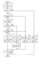
- FIG. 1 is an overall block diagram of a vehicle. It is a figure which shows the circuit structure of 1st MG, 2nd MG, PCU, a battery, and EHC. It is a functional block diagram of ECU. It is a flowchart which shows the process sequence of ECU.
- FIG. 6 is a diagram (part 1) illustrating time variation of brake torque and EHC state;
- FIG. 6 is a diagram (part 2) showing time changes in brake torque and EHC state;
- FIG. 1 is an overall block diagram of a vehicle 1 according to the present embodiment.
- the vehicle 1 includes an engine 10, a first MG (Motor Generator) 20, a second MG 30, a power split device 40, a speed reducer 50, a PCU (Power Control Unit) 60, a battery 70, drive wheels 80, An ECB (Electronically Controlled Brake System) 90 and an ECU (Electronic Control Unit) 200 are provided.
- the vehicle 1 is a hybrid vehicle that travels by driving force from at least one of the engine 10 and the second MG 30.
- the driving method of the vehicle 1 may be other than the hybrid method.
- the engine 10 is an internal combustion engine that generates a driving force for rotating a crankshaft by combustion energy generated when an air-fuel mixture is combusted.
- Engine 10 is controlled by a control signal from ECU 200.
- the power generated by the engine 10 is divided by the power split device 40 into a path transmitted to the drive wheels 80 and a path transmitted to the first MG 20.
- First MG 20 and second MG 30 are motor generators driven by alternating current.
- First MG 20 generates power using the power of engine 10 divided by power split device 40.
- the electric power generated by first MG 20 is supplied to battery 70 and second MG 30.
- the second MG 30 generates a driving force using at least one of the electric power supplied from the battery 70 and the electric power generated by the first MG 20. Then, the driving force of the second MG 30 is transmitted to the driving wheel 80.
- the second MG 30 is driven by the drive wheels 80, and the second MG 30 operates as a generator. Thereby, the second MG 30 functions as a regenerative brake that converts the kinetic energy of the vehicle 1 into electric energy.
- the regenerative power generated by the regenerative power generation by the second MG 30 is charged to the battery 70 via the PCU 60.
- the regenerative power is also supplied to the EHC 140 as necessary.
- the power split device 40 includes a planetary gear including a sun gear, a pinion gear, a carrier, and a ring gear.
- the pinion gear engages with the sun gear and the ring gear.
- the carrier supports the pinion gear so as to be capable of rotating, and is connected to the crankshaft of the engine 10.
- the sun gear is connected to the rotation shaft of the first MG 20.
- the ring gear is connected to the rotation shaft of second MG 30 and speed reducer 50.
- the engine 10, the first MG 20, and the second MG 30 are connected via the power split device 40 including the planetary gears, so that the rotation speed of the engine 10, the rotation speed of the first MG 20, and the rotation speed of the second MG 30 are as follows.
- a relationship is established by a straight line (a relationship in which the remaining one value is determined if any two values are determined).
- the PCU 60 is controlled by a control signal from the ECU 200.
- PCU 60 converts the DC power supplied from battery 70 into AC power that can drive first MG 20 and second MG 30.
- PCU 60 outputs the converted AC power to first MG 20 and second MG 30, respectively.
- first MG 20 and second MG 30 are driven by the electric power stored in battery 70.
- the PCU 60 can also convert AC power generated by the first MG 20 and the second MG 30 into DC power and charge the battery 70 with the converted DC power.
- the battery 70 is a direct current power source that stores electric power for driving the first MG 20 and the second MG 30, and includes, for example, a secondary battery such as nickel hydride or lithium ion.
- the output voltage of the battery 70 is a high voltage exceeding 200 V, for example. Note that a large-capacity capacitor may be used instead of the battery 70.
- ECB 400 causes hydraulic brake torque to act on drive wheels 80 in accordance with a control signal from ECU 200.
- the structure itself of the ECB 400 may be the same as the conventional structure.
- the ECB 400 applies hydraulic brake torque not only to the drive wheel 80 but also to the driven wheel (rear wheel in FIG. 1).
- the vehicle 1 includes a position sensor 2 and a stroke sensor 3.
- the position sensor 2 detects the accelerator pedal operation amount A by the user.
- the stroke sensor 3 detects a brake pedal operation amount B by the user.
- Each of these sensors transmits a signal representing the detection result to ECU 200.
- the vehicle 1 includes an exhaust passage 130. Exhaust gas discharged from the engine 10 passes through the exhaust passage 130 and is discharged to the atmosphere.
- an electrically heated catalyst (electrically heated catalyst, hereinafter referred to as "EHC") 140 is provided.
- the EHC 140 is a catalyst configured such that the catalyst can be electrically heated by an electric heater (electric resistance that converts electric energy into heat energy).
- the EHC 140 has a function of consuming a large amount of power to raise the temperature of the catalyst to a high temperature.
- the EHC 140 includes an electric heater that generates heat by consuming electric power (eg, DC power of about 650 volts) after being boosted by the converter 61, and the electric heater raises the temperature of the catalyst to a high temperature.
- Electric power eg, DC power of about 650 volts
- FIG. 2 is a diagram showing a circuit configuration of the first MG 20, the second MG 30, the PCU 60, the battery 70, and the EHC 140.
- a system main relay (SMR) 71 is provided between the PCU 60 and the battery 70.
- the SMR 71 is controlled by a control signal from the ECU 200 and switches between power supply and interruption between the battery 70 and the PCU 60.
- the PCU 60 includes a converter 61, inverters 62 and 63, smoothing capacitors 64 and 65, and a discharge resistor 66.
- Converter 61 is connected to battery 70 via positive line PL1 and negative line NL1.
- Converter 61 is connected to inverters 62 and 63 via positive line PL2 and negative line NL1.
- Converter 61 includes a reactor, two switching elements, and two diodes. Converter 61 is controlled by a control signal from ECU 200 and performs voltage conversion between battery 70 and inverters 62 and 63.
- the inverter 62 is provided between the converter 61 and the first MG 20.
- Inverter 63 is provided between converter 61 and second MG 30. Inverters 62 and 63 are connected to converter 61 in parallel.
- Each of inverters 62 and 63 includes a three-phase upper and lower arm (switching element) and a diode connected in antiparallel to each switching element.
- Each of the upper and lower arms of the inverters 62 and 63 is controlled by a control signal from the ECU 200, converts the DC power converted by the converter 61 into AC power, and outputs the AC power to the first MG 20 and the second MG 30, respectively.
- the smoothing capacitor 64 is connected between the positive electrode line PL1 and the negative electrode line NL1, and smoothes the AC component of the voltage fluctuation between the positive electrode line PL1 and the negative electrode line NL1.
- Smoothing capacitor 65 is connected between positive electrode line PL2 and negative electrode line NL1, and smoothes an AC component of voltage fluctuation between positive electrode line PL2 and negative electrode line NL1.
- the discharge resistor 66 is connected between the positive electrode line PL2 and the negative electrode line NL1.
- the discharge resistor 66 is used to remove residual charges from the smoothing capacitors 64 and 65. Therefore, the capacity of the discharge resistor 66 (the amount of power that can be consumed per unit time) is smaller than that of the EHC 140.
- EHC 140 is connected to a power line (positive line PL2, negative line NL1) between converter 61 and inverters 62 and 63. More specifically, one end of the electric heater provided in the EHC 140 is connected to the positive branch line PLehc branched from the positive line PL2, and the other end is connected to the negative branch line NLehc branched from the negative line NL1. The Thereby, EHC 140 is overheated with electric power supplied from positive electrode line PL2. In other words, EHC 140 is heated by consuming electric power after boosting electric power of battery 70 by converter 61.
- battery 70 and converter 61 in the present embodiment are used not only as a hybrid power source (power source for driving second MG 30) but also as an EHC power source (power source for heating EHC 140).
- EHC 140 consumes regenerative power generated by first MG 20 and / or second MG 30 (more precisely, power after conversion of regenerative power to DC power by inverters 62 and 63) during braking of vehicle 1. Is also heated.
- a switching device 100 is provided between the EHC 140 and the PCU 60.
- the switching device 100 includes an EHC relay R1 provided on the positive branch line PLehc, an EHC relay R2 provided on the negative branch line NLehc, and a monitoring sensor 120 that monitors the states of the EHC 140 and the EHC relays R1 and R2. Prepare inside.
- the monitoring sensor 120 calculates the power consumption of the EHC 140 (hereinafter also referred to as “EHC power consumption Pehc”), the estimated temperature of the EHC 140, the electrical resistance value of the EHC 140, and the like from the voltage value and the current value supplied to the EHC 140. Is output to the ECU 200. Note that all or part of the functions of the monitoring sensor 120 may be provided outside the switching device 100.
- Opening / closing (ON / OFF) of each EHC relay R1, R2 is controlled by a control signal from the ECU 200.
- EHC ON EHC ON
- EHC 140 and PCU 60 are electrically connected, and power is supplied to EHC 140.
- the catalyst in the EHC 140 is warmed up.
- EHC off at least one of the EHC relays R1 and R2 is opened
- the electrical connection between the EHC 140 and the PCU 60 is cut off, and the power supply to the EHC 140 is stopped. .
- the supply and stop of power to the EHC 140 can be switched with a relatively simple and inexpensive configuration in which the ECU 200 controls the opening and closing of the EHC relays R1 and R2.
- the ECU 200 includes a CPU (Central Processing Unit) (not shown) and a memory, and is configured to execute predetermined arithmetic processing based on information stored in the memory.
- a CPU Central Processing Unit
- memory e.g., a random access memory
- ECU 200 is shown as one unit in FIG. 1, ECU 200 may be divided into two or more units.
- the ECU 200 sets the battery acceptable power WIN (unit: watts) according to the state of charge (SOC: State Of Charge) of the battery 70 and the temperature, and the power actually received by the battery 70 (hereinafter referred to as “battery received power”).
- the PCU 60 is controlled so that “Pin (unit: Watts)” does not exceed the battery acceptable power WIN. Thereby, overcharge of the battery 70 is suppressed, and deterioration of the battery 70 is suppressed.
- the second MG 30 functions as a regenerative brake by controlling the second MG 30 to generate regenerative power. Can be made. At this time, the kinetic energy of the vehicle 1 can be recovered as electric energy by charging the battery 70 with the regenerative energy generated by the second MG 30.
- the regenerative power (unit: watts) exceeds the battery acceptable power WIN when charging the regenerative energy to the battery 70, how to consume the surplus power exceeding the battery acceptable power WIN becomes a problem.
- the EHC relays R1 and R2 by closing the EHC relays R1 and R2 and supplying regenerative power to both the battery 70 and the EHC 140, a part of the regenerative power including surplus power is effectively used as energy for EHC heating. Can do. Thereby, it is possible to efficiently recover the kinetic energy of the vehicle 1 without wasting it while suppressing overcharge of the battery 70.
- the battery 70 and the converter 61 are shared as a hybrid power source and an EHC power source, and there is no EHC dedicated battery and converter. Therefore, it is not possible to accurately and continuously reduce the amount of power supplied to the EHC 140.
- the ECU 200 stops the power supply to the EHC 140 when the vehicle 1 is in regenerative braking in the EHC on state (that is, when regenerative power is supplied to both the battery 70 and the EHC 140).
- the power condition condition for turning off EHC
- the turning off of EHC is temporarily delayed, and the regenerative brake is replaced with a hydraulic brake by ECB 90 during the delay of turning off EHC.
- the ECU 200 cancels the EHC off delay after the replacement from the regenerative brake to the hydraulic brake is completed (allows the EHC to be turned off).
- FIG. 3 is a functional block diagram of the ECU 200. Each functional block shown in FIG. 3 may be realized by hardware or software.
- ECU 200 includes a required torque calculation unit 210, determination units 220, 230, and 260, an EHC off delay unit 250, a brake torque control unit 270, and an EHC off delay release unit 280.
- the required torque calculation unit 210 calculates the user required brake torque Tbkmc based on the brake pedal operation amount B from the stroke sensor 3 and the like. Then, required torque calculation unit 210 calculates regenerative request brake torque Tpbrq within a range that does not exceed user required brake torque Tbkmc.
- the determination unit 220 performs EHC on / off determination. Specifically, the determination unit 220 determines whether the EHC is on or the EHC is off.
- the determination unit 230 When the EHC is in an ON state, the determination unit 230 performs a WIN excess determination when the EHC is off.
- the EHC off WIN excess determination is a process for determining whether or not the battery received power Pin is predicted to exceed the battery acceptable power WIN when the EHC is off. For example, determination unit 230 determines that regeneration request brake torque Tpbrq is larger than regenerative brake torque (hereinafter referred to as “battery allowable torque Twin”) when second MG 30 generates regenerative power corresponding to battery-acceptable power WIN. , It is predicted that “WIN exceeds WIN when EHC is off (Pin> WIN when EHC is off)”.
- the EHC off delay unit 250 performs EHC off delay processing when it is predicted that “WIN exceeds WIN when EHC is off”.
- the EHC off delay process is a process for temporarily delaying the EHC off.
- the EHC off delay unit 250 outputs a command for performing the EHC off delay to an EHC control unit (not shown). This temporarily delays turning off the EHC.
- the determination unit 260 determines whether or not a condition for turning off the EHC is satisfied after the EHC off delay process is performed. Specifically, determination section 260 determines whether or not “EHC off advance notice” is present and “EHC immediate off request” is present.
- the “EHC off notice” is a notice that the EHC 140 will be turned off in the near future (after a predetermined time has elapsed) in order to avoid the EHC 140 from being overheated. For example, when an EHC control unit (not shown) predicts that the EHC temperature after a predetermined time has exceeded the allowable temperature from the estimated temperature of the EHC 140 and the amount of power consumption, an “EHC off notice” is output.
- the “EHC immediate turn-off request” is a request to immediately turn off EHC.
- the EHC control unit determines that the power supply to the EHC 140 cannot be normally performed
- an “EHC immediate OFF request” is output.
- the electrical resistance of EHC140 rises from a normal value due to internal damage of EHC140
- the EHC power consumption Pehc becomes zero, the decrease rate of the EHC power consumption Pehc exceeds a reference value, and the like.
- the brake torque control unit 270 sets the regeneration execution brake torque Tpb and the hydraulic brake torque Tpbfric so as to realize the user requested brake torque Tbkmc. Then, the brake torque control unit 270 outputs a command for changing the actual regenerative brake torque to the regenerative execution brake torque Tpb to the second MG 30 (more precisely, the inverter 63 in the PCU 63), and the actual hydraulic brake torque. A command for setting the hydraulic brake torque Tpbfric to the ECB 90 is output.
- the brake torque control unit 270 changes the setting method of the regeneration execution brake torque Tpb and the hydraulic brake torque Tpbfric according to the determination results by the determination units 220, 230, and 260.
- the “WIN guard process” is a process of limiting the upper limit of the regenerative brake torque Tpb so that the regenerative power is less than the battery acceptable power WIN.
- the regenerative request brake torque Tpbrq is smaller than the above-described battery allowable torque Twin, the regenerative request brake torque Tpbrq is set as the regenerative execution brake torque Tpb as it is, but the regenerative request brake torque is more than the battery allowable torque Twin.
- Tpbrq is large, not the regenerative request brake torque Tpbrq but the battery allowable torque Twin is set as the regenerative execution brake torque Tpb. This prevents battery acceptance power Pin from exceeding battery acceptance power WIN (battery overcharge).
- the brake torque control unit 270 shares the regeneration execution brake torque Tpb and the hydraulic brake torque Tpbfric. Is determined using the battery acceptable power WIN and the EHC power consumption Pehc. Specifically, the brake torque control unit 270 shares the value after the (WIN + Pehc) guard process is performed on the regenerative request brake torque Tpbrq with the regenerative execution brake torque Tpb, and the regenerative execution brake among the user requested brake torque Tbkmc. Torque exceeding the torque Tpb is shared by the hydraulic brake torque Tpbfric.
- the “(WIN + Pehc) guard process” is a process of limiting the upper limit of the regenerative execution brake torque Tpb so that the regenerative power is less than the total value of the battery acceptable power WIN and the EHC power consumption Pehc.
- EHC permissible torque Tehc_min the total value of the regenerative brake torque
- the regenerative request brake torque Tpbrq is set to the regenerative request brake torque Tpbrq as it is, but the regenerative request brake torque Tpbrq is larger than the total value of the EHC allowable torque Tpehc_min and the battery allowable torque Twin.
- the “minimum value of EHC power consumption Pehc_min” is used instead of the EHC power consumption Pehc itself, considering that the EHC power consumption Pehc varies depending on the state of the EHC 140. This is to prevent the battery received power Pin from exceeding the battery acceptable power WIN even when the power Pehc is reduced.
- the minimum value Pehc_min of EHC power consumption may be a value set from the history of EHC power consumption Pehc from the monitoring sensor 120, or may be a value set in advance through experiments or the like. Note that the measured EHC power consumption Pehc may be used as long as the actual EHC power consumption Pehc can be accurately measured with a sensor or the like.
- the brake torque control unit 270 determines that the regenerative power is less than the battery acceptable power WIN.
- the regenerative execution brake torque Tpb is gradually reduced (gradually) so that the hydraulic brake torque Tpbfric is gradually increased as the regenerative execution brake torque Tpb decreases (hereinafter, such control is referred to as “first alternative”). Also called “control”).
- the brake torque control unit 270 gradually decreases the regenerative execution brake torque Tpb at a change rate less than a predetermined change rate until it becomes less than the battery allowable torque Twin, and sets the hydraulic brake torque Tpbfric to (Tbkmc ⁇ Tpb).
- the regenerative execution brake torque Tpb is gradually replaced with the hydraulic brake torque Tpbfric until the regenerative power becomes less than the battery acceptable power WIN. Therefore, the regenerative power can be reduced below the battery acceptable power WIN without giving the user a sense of incongruity.
- the brake torque control unit 270 regenerates so that the regenerative power becomes zero.
- the execution brake torque Tpb is immediately decreased at a change rate equal to or higher than a predetermined change rate (the regenerative power generation of the second MG 30 is immediately interrupted), and the hydraulic brake torque Tpbfric is increased by the decrease in the regenerative execution brake torque Tpb (hereinafter referred to as “regeneration execution brake torque Tpb”).
- This control is also referred to as “second alternative control”).
- regenerative power generation is immediately interrupted and regenerative power is not supplied to the battery 70, so that battery overcharge is suppressed.
- the regenerative execution brake torque Tpb is abruptly replaced with the hydraulic brake torque Tpbfric, which may cause a delay in the actual increase of the hydraulic brake torque and may give the user some discomfort.
- the degree of urgency suppression of battery overcharge is given priority over suppression of deterioration of drivability.
- the EHC off delay canceling unit 280 performs processing for canceling the EHC off delay when the first alternative control or the second alternative control is completed during the EHC off delay. This allows the EHC to be turned off.
- FIG. 4 is a flowchart showing a processing procedure for realizing the functions of the ECU 200 described above.
- step (hereinafter, step is abbreviated as “S”) 10 ECU 200 calculates user-requested brake torque Tbkmc.
- step 20 ECU 200 calculates regeneration request brake torque Tpbrq.
- step 30 ECU 200 determines whether or not the EHC is on.
- ECU 200 sets the value after the WIN guard process is applied to regeneration required brake torque Tpbrq in S31 as regeneration execution brake torque Tpb, and the user requested brake in S32.
- ECU 200 determines in S40 whether or not it is predicted that “WIN exceeds EHC when WIN is off”.
- ECU 200 When it is predicted that “WIN over EHC is off” (YES in S40), ECU 200 performs an EHC off delay process in S50, determines whether or not “EHC off notice” is present in S60, and then proceeds to S70. To determine whether there is an “EHC immediate OFF request”.
- the ECU 200 When neither the “EHC off advance notice” nor the “EHC immediate off request” is made (NO in both S60 and S70), the ECU 200 performs the guard process on the regeneration required brake torque Tpbrq in (S41 and SWIN) after applying the (WIN + Pehc) guard process.
- ECU 200 determines the value obtained by subtracting a predetermined minute amount ⁇ T from the regeneration execution brake torque Tpb of the previous cycle as the regeneration execution brake torque Tpb of the current cycle in S61.
- the regenerative execution brake torque Tpb is gradually reduced at a change rate less than the predetermined change rate, and the hydraulic brake torque Tpbfric is set to (Tbkmc ⁇ Tpb) in S62, so that the hydraulic brake torque Tpbfric is changed to the regenerative execution brake torque Tpb.
- step S63 the ECU 200 determines whether or not the regenerative power is less than the battery acceptable power WIN (whether or not the regenerative execution brake torque Tpb is less than the battery allowable torque Twin). If the regenerative power is not less than WIN (NO in S63), ECU 200 returns the process to S61 and repeats the processes of S61 and S62 until the regenerative power becomes less than WIN. A series of processes of S61 to S63 corresponds to the first alternative control described above. If the regenerative power is less than WIN (YES in S63), ECU 200 moves the process to S80.
- ECU 200 when there is an “EHC immediate OFF request” (YES in S70), ECU 200 immediately interrupts regenerative power generation of second MG 30 by reducing regenerative execution brake torque Tpb to 0 in S71, and S72.
- the hydraulic brake torque Tpbfric is immediately increased to the user requested brake torque Tbkmc.
- the processes of S71 and S72 correspond to the second alternative control described above. Thereafter, the ECU 200 moves the process to S80.
- ECU 200 cancels the EHC off delay. This allows the EHC to be turned off.
- FIG. 5 is a diagram showing temporal changes in the brake torque and the EHC state when the first alternative control is performed.
- the first alternative control is started. That is, the regenerative execution brake torque Tpb is gradually reduced so that the regenerative power becomes less than the battery acceptable power WIN, and the hydraulic brake torque Tpbfric is gradually increased in accordance with the decrease in the regenerative execution brake torque Tpb. Thereby, regenerative electric power can be reduced, without giving a user discomfort.
- the “EHC off delay” is canceled and the EHC is turned off.
- the power consumed by the EHC 140 is supplied to the battery 70 and all the regenerative power is supplied to the battery 70.
- the regenerative power is less than the battery acceptable power WIN, so the battery is overcharged. Is prevented.
- FIG. 6 is a diagram showing temporal changes in the brake torque and the EHC state when the second alternative control is performed.
- the ECU 200 should turn off the EHC when the vehicle 1 is performing regenerative braking while the EHC is on (when regenerative power is supplied to both the battery 70 and the EHC 140).
- the regenerative brake is replaced with a hydraulic brake after delaying EHC off temporarily.
- ECU 200 cancels the EHC off delay (allows EHC off).
Landscapes
- Engineering & Computer Science (AREA)
- Mechanical Engineering (AREA)
- Transportation (AREA)
- Power Engineering (AREA)
- Chemical & Material Sciences (AREA)
- Combustion & Propulsion (AREA)
- Automation & Control Theory (AREA)
- Chemical Kinetics & Catalysis (AREA)
- Health & Medical Sciences (AREA)
- General Engineering & Computer Science (AREA)
- Toxicology (AREA)
- Sustainable Development (AREA)
- Sustainable Energy (AREA)
- Physics & Mathematics (AREA)
- Electromagnetism (AREA)
- Life Sciences & Earth Sciences (AREA)
- Electric Propulsion And Braking For Vehicles (AREA)
- Hybrid Electric Vehicles (AREA)
- Regulating Braking Force (AREA)
- Exhaust Gas After Treatment (AREA)
Priority Applications (5)
| Application Number | Priority Date | Filing Date | Title |
|---|---|---|---|
| JP2013545711A JP5761371B2 (ja) | 2011-11-24 | 2011-11-24 | 車両および車両の制御方法 |
| US14/357,646 US9469293B2 (en) | 2011-11-24 | 2011-11-24 | Vehicle and control method for vehicle |
| EP11876292.1A EP2783936B1 (de) | 2011-11-24 | 2011-11-24 | Fahrzeug und fahrzeugsteuerungsverfahren |
| CN201180074996.5A CN103946093B (zh) | 2011-11-24 | 2011-11-24 | 车辆和车辆的控制方法 |
| PCT/JP2011/077025 WO2013076836A1 (ja) | 2011-11-24 | 2011-11-24 | 車両および車両の制御方法 |
Applications Claiming Priority (1)
| Application Number | Priority Date | Filing Date | Title |
|---|---|---|---|
| PCT/JP2011/077025 WO2013076836A1 (ja) | 2011-11-24 | 2011-11-24 | 車両および車両の制御方法 |
Publications (1)
| Publication Number | Publication Date |
|---|---|
| WO2013076836A1 true WO2013076836A1 (ja) | 2013-05-30 |
Family
ID=48469315
Family Applications (1)
| Application Number | Title | Priority Date | Filing Date |
|---|---|---|---|
| PCT/JP2011/077025 WO2013076836A1 (ja) | 2011-11-24 | 2011-11-24 | 車両および車両の制御方法 |
Country Status (5)
| Country | Link |
|---|---|
| US (1) | US9469293B2 (de) |
| EP (1) | EP2783936B1 (de) |
| JP (1) | JP5761371B2 (de) |
| CN (1) | CN103946093B (de) |
| WO (1) | WO2013076836A1 (de) |
Cited By (5)
| Publication number | Priority date | Publication date | Assignee | Title |
|---|---|---|---|---|
| CN104234797A (zh) * | 2013-06-19 | 2014-12-24 | 上海汽车集团股份有限公司 | 用于优化插电式混合动力汽车排放的催化器加热控制方法 |
| JP2015041653A (ja) * | 2013-08-21 | 2015-03-02 | 株式会社ディスコ | 加工装置 |
| US20160121727A1 (en) * | 2014-10-30 | 2016-05-05 | Hyundai Motor Company | Braking control method for eco-friendly vehicle |
| JP2020028182A (ja) * | 2018-08-10 | 2020-02-20 | 株式会社Subaru | 充電システム |
| JP2021054155A (ja) * | 2019-09-27 | 2021-04-08 | いすゞ自動車株式会社 | ハイブリッド車両電力供給システム |
Families Citing this family (7)
| Publication number | Priority date | Publication date | Assignee | Title |
|---|---|---|---|---|
| JP6376169B2 (ja) * | 2016-04-20 | 2018-08-22 | トヨタ自動車株式会社 | ハイブリッド車両 |
| DE102016218858A1 (de) | 2016-09-29 | 2018-03-29 | Audi Ag | Zeitoptimierte Partikelfilterregeneration bei Hybridfahrzeugen |
| KR102304853B1 (ko) * | 2017-07-31 | 2021-09-27 | 현대자동차주식회사 | 하이브리드 자동차 및 그 모터 제어 방법 |
| JP6958484B2 (ja) * | 2018-05-29 | 2021-11-02 | トヨタ自動車株式会社 | 車両用制御装置 |
| KR20200115820A (ko) * | 2019-03-27 | 2020-10-08 | 현대자동차주식회사 | 하이브리드 자동차 및 그를 위한 제동 제어 방법 |
| FR3100511B1 (fr) * | 2019-09-05 | 2022-05-20 | Continental Automotive Gmbh | Calculateur de contrôle d’une chaîne de traction d’un véhicule hybride |
| DE102019124788A1 (de) * | 2019-09-16 | 2020-08-20 | Audi Ag | Verfahren zum Betreiben einer Antriebseinrichtung für ein Kraftfahrzeug sowie entsprechende Antriebseinrichtung |
Citations (8)
| Publication number | Priority date | Publication date | Assignee | Title |
|---|---|---|---|---|
| JPH10238381A (ja) | 1997-02-25 | 1998-09-08 | Denso Corp | ハイブリッド車制御装置 |
| JPH114503A (ja) * | 1997-06-10 | 1999-01-06 | Toyota Motor Corp | 車両用制動装置 |
| JP2003127721A (ja) * | 2001-10-25 | 2003-05-08 | Toyota Motor Corp | 車輌用制動制御装置 |
| JP2004245135A (ja) | 2003-02-14 | 2004-09-02 | Mitsubishi Motors Corp | 車両用の電力制御装置 |
| JP2005002989A (ja) | 2003-05-21 | 2005-01-06 | Toyota Motor Corp | 動力出力装置およびその制御方法並びに自動車 |
| JP2009189921A (ja) | 2008-02-13 | 2009-08-27 | Toyota Motor Corp | 通電加熱式触媒装置の通電制御システム |
| JP2009214703A (ja) | 2008-03-11 | 2009-09-24 | Nissan Motor Co Ltd | ハイブリッド車両の制御装置 |
| JP2011167030A (ja) | 2010-02-15 | 2011-08-25 | Toyota Motor Corp | 電動車両の制御装置 |
Family Cites Families (8)
| Publication number | Priority date | Publication date | Assignee | Title |
|---|---|---|---|---|
| JP3573206B2 (ja) * | 2002-03-12 | 2004-10-06 | トヨタ自動車株式会社 | 車両制御装置 |
| JP2004360289A (ja) * | 2003-06-04 | 2004-12-24 | Bunka Shutter Co Ltd | 開閉装置 |
| JP2006174543A (ja) * | 2004-12-13 | 2006-06-29 | Honda Motor Co Ltd | ハイブリッド車両における回生電力制御装置 |
| JP4175370B2 (ja) * | 2006-01-13 | 2008-11-05 | トヨタ自動車株式会社 | ハイブリッド車両およびその制御方法 |
| US8630759B2 (en) | 2009-11-20 | 2014-01-14 | GM Global Technology Operations LLC | Control of regenerative braking in a hybrid vehicle |
| DE102010004436A1 (de) * | 2010-01-13 | 2011-07-14 | Bayerische Motoren Werke Aktiengesellschaft, 80809 | Kraftfahrzeug mit elektromotorischem Antrieb |
| US9028366B2 (en) * | 2011-02-16 | 2015-05-12 | Toyota Jidosha Kabushiki Kaisha | Vehicle and method for controlling vehicle |
| JP5622055B2 (ja) * | 2012-07-02 | 2014-11-12 | 株式会社デンソー | ハイブリッド車の制御装置 |
-
2011
- 2011-11-24 US US14/357,646 patent/US9469293B2/en active Active
- 2011-11-24 WO PCT/JP2011/077025 patent/WO2013076836A1/ja active Application Filing
- 2011-11-24 JP JP2013545711A patent/JP5761371B2/ja active Active
- 2011-11-24 EP EP11876292.1A patent/EP2783936B1/de not_active Not-in-force
- 2011-11-24 CN CN201180074996.5A patent/CN103946093B/zh not_active Expired - Fee Related
Patent Citations (8)
| Publication number | Priority date | Publication date | Assignee | Title |
|---|---|---|---|---|
| JPH10238381A (ja) | 1997-02-25 | 1998-09-08 | Denso Corp | ハイブリッド車制御装置 |
| JPH114503A (ja) * | 1997-06-10 | 1999-01-06 | Toyota Motor Corp | 車両用制動装置 |
| JP2003127721A (ja) * | 2001-10-25 | 2003-05-08 | Toyota Motor Corp | 車輌用制動制御装置 |
| JP2004245135A (ja) | 2003-02-14 | 2004-09-02 | Mitsubishi Motors Corp | 車両用の電力制御装置 |
| JP2005002989A (ja) | 2003-05-21 | 2005-01-06 | Toyota Motor Corp | 動力出力装置およびその制御方法並びに自動車 |
| JP2009189921A (ja) | 2008-02-13 | 2009-08-27 | Toyota Motor Corp | 通電加熱式触媒装置の通電制御システム |
| JP2009214703A (ja) | 2008-03-11 | 2009-09-24 | Nissan Motor Co Ltd | ハイブリッド車両の制御装置 |
| JP2011167030A (ja) | 2010-02-15 | 2011-08-25 | Toyota Motor Corp | 電動車両の制御装置 |
Cited By (8)
| Publication number | Priority date | Publication date | Assignee | Title |
|---|---|---|---|---|
| CN104234797A (zh) * | 2013-06-19 | 2014-12-24 | 上海汽车集团股份有限公司 | 用于优化插电式混合动力汽车排放的催化器加热控制方法 |
| CN104234797B (zh) * | 2013-06-19 | 2016-11-16 | 上海汽车集团股份有限公司 | 用于优化插电式混合动力汽车排放的催化器加热控制方法 |
| JP2015041653A (ja) * | 2013-08-21 | 2015-03-02 | 株式会社ディスコ | 加工装置 |
| US20160121727A1 (en) * | 2014-10-30 | 2016-05-05 | Hyundai Motor Company | Braking control method for eco-friendly vehicle |
| US9834096B2 (en) * | 2014-10-30 | 2017-12-05 | Hyundai Motor Company | Braking control method for eco-friendly vehicle |
| JP2020028182A (ja) * | 2018-08-10 | 2020-02-20 | 株式会社Subaru | 充電システム |
| JP7161340B2 (ja) | 2018-08-10 | 2022-10-26 | 株式会社Subaru | 充電システム |
| JP2021054155A (ja) * | 2019-09-27 | 2021-04-08 | いすゞ自動車株式会社 | ハイブリッド車両電力供給システム |
Also Published As
| Publication number | Publication date |
|---|---|
| EP2783936A1 (de) | 2014-10-01 |
| EP2783936B1 (de) | 2018-05-30 |
| JPWO2013076836A1 (ja) | 2015-04-27 |
| US9469293B2 (en) | 2016-10-18 |
| JP5761371B2 (ja) | 2015-08-12 |
| CN103946093A (zh) | 2014-07-23 |
| US20150057857A1 (en) | 2015-02-26 |
| EP2783936A4 (de) | 2016-03-23 |
| CN103946093B (zh) | 2016-08-24 |
Similar Documents
| Publication | Publication Date | Title |
|---|---|---|
| JP5761371B2 (ja) | 車両および車両の制御方法 | |
| KR101622525B1 (ko) | 하이브리드 차량 | |
| JP5382238B2 (ja) | ハイブリッド車両およびその制御方法 | |
| US9074509B2 (en) | Control apparatus for vehicle | |
| JP5716681B2 (ja) | 車両および車両の制御方法 | |
| JP5333573B2 (ja) | 車両の制御装置および制御方法 | |
| JP2007221886A (ja) | 二次電池の充放電制御装置 | |
| JPWO2012066675A1 (ja) | 車両の充電装置 | |
| JP5928326B2 (ja) | 電動車両および電動車両の制御方法 | |
| JP5729475B2 (ja) | 車両および車両の制御方法 | |
| JP5803507B2 (ja) | ハイブリッド車両の制御装置およびハイブリッド車両 | |
| JP2006280161A (ja) | ハイブリッド電気自動車用回生制御装置 | |
| JP5923906B2 (ja) | 車両および車両の制御方法 | |
| JP2010115035A (ja) | 電池保護装置 | |
| JP6798437B2 (ja) | 電動車両 | |
| JP2010215106A (ja) | ハイブリッド車両の制御システム | |
| JP5949365B2 (ja) | 電源システム | |
| JP5545372B2 (ja) | 車両の制御装置および制御方法 | |
| JP5641145B2 (ja) | 車両および車両の制御方法 | |
| JP2015013517A (ja) | 車両の制御装置 | |
| JP2021138242A (ja) | ハイブリッド車両およびその廃電制御方法 |
Legal Events
| Date | Code | Title | Description |
|---|---|---|---|
| 121 | Ep: the epo has been informed by wipo that ep was designated in this application |
Ref document number: 11876292 Country of ref document: EP Kind code of ref document: A1 |
|
| ENP | Entry into the national phase |
Ref document number: 2013545711 Country of ref document: JP Kind code of ref document: A |
|
| WWE | Wipo information: entry into national phase |
Ref document number: 14357646 Country of ref document: US |
|
| WWE | Wipo information: entry into national phase |
Ref document number: 2011876292 Country of ref document: EP |
|
| NENP | Non-entry into the national phase |
Ref country code: DE |