WO2013076836A1 - Vehicle, and vehicle control method - Google Patents

Vehicle, and vehicle control method Download PDF

Info

Publication number
WO2013076836A1
WO2013076836A1 PCT/JP2011/077025 JP2011077025W WO2013076836A1 WO 2013076836 A1 WO2013076836 A1 WO 2013076836A1 JP 2011077025 W JP2011077025 W JP 2011077025W WO 2013076836 A1 WO2013076836 A1 WO 2013076836A1
Authority
WO
WIPO (PCT)
Prior art keywords
power
regenerative
brake torque
ehc
torque
Prior art date
Application number
PCT/JP2011/077025
Other languages
French (fr)
Japanese (ja)
Inventor
浩司 勝田
Original Assignee
トヨタ自動車株式会社
Priority date (The priority date is an assumption and is not a legal conclusion. Google has not performed a legal analysis and makes no representation as to the accuracy of the date listed.)
Filing date
Publication date
Application filed by トヨタ自動車株式会社 filed Critical トヨタ自動車株式会社
Priority to EP11876292.1A priority Critical patent/EP2783936B1/en
Priority to JP2013545711A priority patent/JP5761371B2/en
Priority to US14/357,646 priority patent/US9469293B2/en
Priority to CN201180074996.5A priority patent/CN103946093B/en
Priority to PCT/JP2011/077025 priority patent/WO2013076836A1/en
Publication of WO2013076836A1 publication Critical patent/WO2013076836A1/en

Links

Images

Classifications

    • BPERFORMING OPERATIONS; TRANSPORTING
    • B60VEHICLES IN GENERAL
    • B60WCONJOINT CONTROL OF VEHICLE SUB-UNITS OF DIFFERENT TYPE OR DIFFERENT FUNCTION; CONTROL SYSTEMS SPECIALLY ADAPTED FOR HYBRID VEHICLES; ROAD VEHICLE DRIVE CONTROL SYSTEMS FOR PURPOSES NOT RELATED TO THE CONTROL OF A PARTICULAR SUB-UNIT
    • B60W20/00Control systems specially adapted for hybrid vehicles
    • B60W20/10Controlling the power contribution of each of the prime movers to meet required power demand
    • B60W20/13Controlling the power contribution of each of the prime movers to meet required power demand in order to stay within battery power input or output limits; in order to prevent overcharging or battery depletion
    • B60W20/14Controlling the power contribution of each of the prime movers to meet required power demand in order to stay within battery power input or output limits; in order to prevent overcharging or battery depletion in conjunction with braking regeneration
    • BPERFORMING OPERATIONS; TRANSPORTING
    • B60VEHICLES IN GENERAL
    • B60KARRANGEMENT OR MOUNTING OF PROPULSION UNITS OR OF TRANSMISSIONS IN VEHICLES; ARRANGEMENT OR MOUNTING OF PLURAL DIVERSE PRIME-MOVERS IN VEHICLES; AUXILIARY DRIVES FOR VEHICLES; INSTRUMENTATION OR DASHBOARDS FOR VEHICLES; ARRANGEMENTS IN CONNECTION WITH COOLING, AIR INTAKE, GAS EXHAUST OR FUEL SUPPLY OF PROPULSION UNITS IN VEHICLES
    • B60K6/00Arrangement or mounting of plural diverse prime-movers for mutual or common propulsion, e.g. hybrid propulsion systems comprising electric motors and internal combustion engines ; Control systems therefor, i.e. systems controlling two or more prime movers, or controlling one of these prime movers and any of the transmission, drive or drive units Informative references: mechanical gearings with secondary electric drive F16H3/72; arrangements for handling mechanical energy structurally associated with the dynamo-electric machine H02K7/00; machines comprising structurally interrelated motor and generator parts H02K51/00; dynamo-electric machines not otherwise provided for in H02K see H02K99/00
    • B60K6/20Arrangement or mounting of plural diverse prime-movers for mutual or common propulsion, e.g. hybrid propulsion systems comprising electric motors and internal combustion engines ; Control systems therefor, i.e. systems controlling two or more prime movers, or controlling one of these prime movers and any of the transmission, drive or drive units Informative references: mechanical gearings with secondary electric drive F16H3/72; arrangements for handling mechanical energy structurally associated with the dynamo-electric machine H02K7/00; machines comprising structurally interrelated motor and generator parts H02K51/00; dynamo-electric machines not otherwise provided for in H02K see H02K99/00 the prime-movers consisting of electric motors and internal combustion engines, e.g. HEVs
    • B60K6/42Arrangement or mounting of plural diverse prime-movers for mutual or common propulsion, e.g. hybrid propulsion systems comprising electric motors and internal combustion engines ; Control systems therefor, i.e. systems controlling two or more prime movers, or controlling one of these prime movers and any of the transmission, drive or drive units Informative references: mechanical gearings with secondary electric drive F16H3/72; arrangements for handling mechanical energy structurally associated with the dynamo-electric machine H02K7/00; machines comprising structurally interrelated motor and generator parts H02K51/00; dynamo-electric machines not otherwise provided for in H02K see H02K99/00 the prime-movers consisting of electric motors and internal combustion engines, e.g. HEVs characterised by the architecture of the hybrid electric vehicle
    • B60K6/44Series-parallel type
    • B60K6/445Differential gearing distribution type
    • BPERFORMING OPERATIONS; TRANSPORTING
    • B60VEHICLES IN GENERAL
    • B60LPROPULSION OF ELECTRICALLY-PROPELLED VEHICLES; SUPPLYING ELECTRIC POWER FOR AUXILIARY EQUIPMENT OF ELECTRICALLY-PROPELLED VEHICLES; ELECTRODYNAMIC BRAKE SYSTEMS FOR VEHICLES IN GENERAL; MAGNETIC SUSPENSION OR LEVITATION FOR VEHICLES; MONITORING OPERATING VARIABLES OF ELECTRICALLY-PROPELLED VEHICLES; ELECTRIC SAFETY DEVICES FOR ELECTRICALLY-PROPELLED VEHICLES
    • B60L15/00Methods, circuits, or devices for controlling the traction-motor speed of electrically-propelled vehicles
    • B60L15/20Methods, circuits, or devices for controlling the traction-motor speed of electrically-propelled vehicles for control of the vehicle or its driving motor to achieve a desired performance, e.g. speed, torque, programmed variation of speed
    • B60L15/2009Methods, circuits, or devices for controlling the traction-motor speed of electrically-propelled vehicles for control of the vehicle or its driving motor to achieve a desired performance, e.g. speed, torque, programmed variation of speed for braking
    • BPERFORMING OPERATIONS; TRANSPORTING
    • B60VEHICLES IN GENERAL
    • B60LPROPULSION OF ELECTRICALLY-PROPELLED VEHICLES; SUPPLYING ELECTRIC POWER FOR AUXILIARY EQUIPMENT OF ELECTRICALLY-PROPELLED VEHICLES; ELECTRODYNAMIC BRAKE SYSTEMS FOR VEHICLES IN GENERAL; MAGNETIC SUSPENSION OR LEVITATION FOR VEHICLES; MONITORING OPERATING VARIABLES OF ELECTRICALLY-PROPELLED VEHICLES; ELECTRIC SAFETY DEVICES FOR ELECTRICALLY-PROPELLED VEHICLES
    • B60L50/00Electric propulsion with power supplied within the vehicle
    • B60L50/10Electric propulsion with power supplied within the vehicle using propulsion power supplied by engine-driven generators, e.g. generators driven by combustion engines
    • B60L50/15Electric propulsion with power supplied within the vehicle using propulsion power supplied by engine-driven generators, e.g. generators driven by combustion engines with additional electric power supply
    • BPERFORMING OPERATIONS; TRANSPORTING
    • B60VEHICLES IN GENERAL
    • B60LPROPULSION OF ELECTRICALLY-PROPELLED VEHICLES; SUPPLYING ELECTRIC POWER FOR AUXILIARY EQUIPMENT OF ELECTRICALLY-PROPELLED VEHICLES; ELECTRODYNAMIC BRAKE SYSTEMS FOR VEHICLES IN GENERAL; MAGNETIC SUSPENSION OR LEVITATION FOR VEHICLES; MONITORING OPERATING VARIABLES OF ELECTRICALLY-PROPELLED VEHICLES; ELECTRIC SAFETY DEVICES FOR ELECTRICALLY-PROPELLED VEHICLES
    • B60L58/00Methods or circuit arrangements for monitoring or controlling batteries or fuel cells, specially adapted for electric vehicles
    • B60L58/10Methods or circuit arrangements for monitoring or controlling batteries or fuel cells, specially adapted for electric vehicles for monitoring or controlling batteries
    • B60L58/12Methods or circuit arrangements for monitoring or controlling batteries or fuel cells, specially adapted for electric vehicles for monitoring or controlling batteries responding to state of charge [SoC]
    • B60L58/15Preventing overcharging
    • BPERFORMING OPERATIONS; TRANSPORTING
    • B60VEHICLES IN GENERAL
    • B60LPROPULSION OF ELECTRICALLY-PROPELLED VEHICLES; SUPPLYING ELECTRIC POWER FOR AUXILIARY EQUIPMENT OF ELECTRICALLY-PROPELLED VEHICLES; ELECTRODYNAMIC BRAKE SYSTEMS FOR VEHICLES IN GENERAL; MAGNETIC SUSPENSION OR LEVITATION FOR VEHICLES; MONITORING OPERATING VARIABLES OF ELECTRICALLY-PROPELLED VEHICLES; ELECTRIC SAFETY DEVICES FOR ELECTRICALLY-PROPELLED VEHICLES
    • B60L7/00Electrodynamic brake systems for vehicles in general
    • B60L7/02Dynamic electric resistor braking
    • B60L7/08Controlling the braking effect
    • BPERFORMING OPERATIONS; TRANSPORTING
    • B60VEHICLES IN GENERAL
    • B60LPROPULSION OF ELECTRICALLY-PROPELLED VEHICLES; SUPPLYING ELECTRIC POWER FOR AUXILIARY EQUIPMENT OF ELECTRICALLY-PROPELLED VEHICLES; ELECTRODYNAMIC BRAKE SYSTEMS FOR VEHICLES IN GENERAL; MAGNETIC SUSPENSION OR LEVITATION FOR VEHICLES; MONITORING OPERATING VARIABLES OF ELECTRICALLY-PROPELLED VEHICLES; ELECTRIC SAFETY DEVICES FOR ELECTRICALLY-PROPELLED VEHICLES
    • B60L7/00Electrodynamic brake systems for vehicles in general
    • B60L7/10Dynamic electric regenerative braking
    • BPERFORMING OPERATIONS; TRANSPORTING
    • B60VEHICLES IN GENERAL
    • B60LPROPULSION OF ELECTRICALLY-PROPELLED VEHICLES; SUPPLYING ELECTRIC POWER FOR AUXILIARY EQUIPMENT OF ELECTRICALLY-PROPELLED VEHICLES; ELECTRODYNAMIC BRAKE SYSTEMS FOR VEHICLES IN GENERAL; MAGNETIC SUSPENSION OR LEVITATION FOR VEHICLES; MONITORING OPERATING VARIABLES OF ELECTRICALLY-PROPELLED VEHICLES; ELECTRIC SAFETY DEVICES FOR ELECTRICALLY-PROPELLED VEHICLES
    • B60L7/00Electrodynamic brake systems for vehicles in general
    • B60L7/24Electrodynamic brake systems for vehicles in general with additional mechanical or electromagnetic braking
    • B60L7/26Controlling the braking effect
    • BPERFORMING OPERATIONS; TRANSPORTING
    • B60VEHICLES IN GENERAL
    • B60WCONJOINT CONTROL OF VEHICLE SUB-UNITS OF DIFFERENT TYPE OR DIFFERENT FUNCTION; CONTROL SYSTEMS SPECIALLY ADAPTED FOR HYBRID VEHICLES; ROAD VEHICLE DRIVE CONTROL SYSTEMS FOR PURPOSES NOT RELATED TO THE CONTROL OF A PARTICULAR SUB-UNIT
    • B60W10/00Conjoint control of vehicle sub-units of different type or different function
    • B60W10/04Conjoint control of vehicle sub-units of different type or different function including control of propulsion units
    • B60W10/08Conjoint control of vehicle sub-units of different type or different function including control of propulsion units including control of electric propulsion units, e.g. motors or generators
    • BPERFORMING OPERATIONS; TRANSPORTING
    • B60VEHICLES IN GENERAL
    • B60WCONJOINT CONTROL OF VEHICLE SUB-UNITS OF DIFFERENT TYPE OR DIFFERENT FUNCTION; CONTROL SYSTEMS SPECIALLY ADAPTED FOR HYBRID VEHICLES; ROAD VEHICLE DRIVE CONTROL SYSTEMS FOR PURPOSES NOT RELATED TO THE CONTROL OF A PARTICULAR SUB-UNIT
    • B60W10/00Conjoint control of vehicle sub-units of different type or different function
    • B60W10/18Conjoint control of vehicle sub-units of different type or different function including control of braking systems
    • B60W10/184Conjoint control of vehicle sub-units of different type or different function including control of braking systems with wheel brakes
    • B60W10/188Conjoint control of vehicle sub-units of different type or different function including control of braking systems with wheel brakes hydraulic brakes
    • BPERFORMING OPERATIONS; TRANSPORTING
    • B60VEHICLES IN GENERAL
    • B60WCONJOINT CONTROL OF VEHICLE SUB-UNITS OF DIFFERENT TYPE OR DIFFERENT FUNCTION; CONTROL SYSTEMS SPECIALLY ADAPTED FOR HYBRID VEHICLES; ROAD VEHICLE DRIVE CONTROL SYSTEMS FOR PURPOSES NOT RELATED TO THE CONTROL OF A PARTICULAR SUB-UNIT
    • B60W20/00Control systems specially adapted for hybrid vehicles
    • BPERFORMING OPERATIONS; TRANSPORTING
    • B60VEHICLES IN GENERAL
    • B60WCONJOINT CONTROL OF VEHICLE SUB-UNITS OF DIFFERENT TYPE OR DIFFERENT FUNCTION; CONTROL SYSTEMS SPECIALLY ADAPTED FOR HYBRID VEHICLES; ROAD VEHICLE DRIVE CONTROL SYSTEMS FOR PURPOSES NOT RELATED TO THE CONTROL OF A PARTICULAR SUB-UNIT
    • B60W30/00Purposes of road vehicle drive control systems not related to the control of a particular sub-unit, e.g. of systems using conjoint control of vehicle sub-units, or advanced driver assistance systems for ensuring comfort, stability and safety or drive control systems for propelling or retarding the vehicle
    • B60W30/18Propelling the vehicle
    • B60W30/18009Propelling the vehicle related to particular drive situations
    • B60W30/18109Braking
    • B60W30/18127Regenerative braking
    • FMECHANICAL ENGINEERING; LIGHTING; HEATING; WEAPONS; BLASTING
    • F01MACHINES OR ENGINES IN GENERAL; ENGINE PLANTS IN GENERAL; STEAM ENGINES
    • F01NGAS-FLOW SILENCERS OR EXHAUST APPARATUS FOR MACHINES OR ENGINES IN GENERAL; GAS-FLOW SILENCERS OR EXHAUST APPARATUS FOR INTERNAL COMBUSTION ENGINES
    • F01N3/00Exhaust or silencing apparatus having means for purifying, rendering innocuous, or otherwise treating exhaust
    • F01N3/08Exhaust or silencing apparatus having means for purifying, rendering innocuous, or otherwise treating exhaust for rendering innocuous
    • F01N3/10Exhaust or silencing apparatus having means for purifying, rendering innocuous, or otherwise treating exhaust for rendering innocuous by thermal or catalytic conversion of noxious components of exhaust
    • F01N3/18Exhaust or silencing apparatus having means for purifying, rendering innocuous, or otherwise treating exhaust for rendering innocuous by thermal or catalytic conversion of noxious components of exhaust characterised by methods of operation; Control
    • F01N3/20Exhaust or silencing apparatus having means for purifying, rendering innocuous, or otherwise treating exhaust for rendering innocuous by thermal or catalytic conversion of noxious components of exhaust characterised by methods of operation; Control specially adapted for catalytic conversion ; Methods of operation or control of catalytic converters
    • F01N3/2006Periodically heating or cooling catalytic reactors, e.g. at cold starting or overheating
    • F01N3/2013Periodically heating or cooling catalytic reactors, e.g. at cold starting or overheating using electric or magnetic heating means
    • BPERFORMING OPERATIONS; TRANSPORTING
    • B60VEHICLES IN GENERAL
    • B60LPROPULSION OF ELECTRICALLY-PROPELLED VEHICLES; SUPPLYING ELECTRIC POWER FOR AUXILIARY EQUIPMENT OF ELECTRICALLY-PROPELLED VEHICLES; ELECTRODYNAMIC BRAKE SYSTEMS FOR VEHICLES IN GENERAL; MAGNETIC SUSPENSION OR LEVITATION FOR VEHICLES; MONITORING OPERATING VARIABLES OF ELECTRICALLY-PROPELLED VEHICLES; ELECTRIC SAFETY DEVICES FOR ELECTRICALLY-PROPELLED VEHICLES
    • B60L2240/00Control parameters of input or output; Target parameters
    • B60L2240/40Drive Train control parameters
    • B60L2240/42Drive Train control parameters related to electric machines
    • B60L2240/423Torque
    • BPERFORMING OPERATIONS; TRANSPORTING
    • B60VEHICLES IN GENERAL
    • B60LPROPULSION OF ELECTRICALLY-PROPELLED VEHICLES; SUPPLYING ELECTRIC POWER FOR AUXILIARY EQUIPMENT OF ELECTRICALLY-PROPELLED VEHICLES; ELECTRODYNAMIC BRAKE SYSTEMS FOR VEHICLES IN GENERAL; MAGNETIC SUSPENSION OR LEVITATION FOR VEHICLES; MONITORING OPERATING VARIABLES OF ELECTRICALLY-PROPELLED VEHICLES; ELECTRIC SAFETY DEVICES FOR ELECTRICALLY-PROPELLED VEHICLES
    • B60L2270/00Problem solutions or means not otherwise provided for
    • B60L2270/10Emission reduction
    • B60L2270/12Emission reduction of exhaust
    • BPERFORMING OPERATIONS; TRANSPORTING
    • B60VEHICLES IN GENERAL
    • B60WCONJOINT CONTROL OF VEHICLE SUB-UNITS OF DIFFERENT TYPE OR DIFFERENT FUNCTION; CONTROL SYSTEMS SPECIALLY ADAPTED FOR HYBRID VEHICLES; ROAD VEHICLE DRIVE CONTROL SYSTEMS FOR PURPOSES NOT RELATED TO THE CONTROL OF A PARTICULAR SUB-UNIT
    • B60W2510/00Input parameters relating to a particular sub-units
    • B60W2510/24Energy storage means
    • B60W2510/242Energy storage means for electrical energy
    • B60W2510/244Charge state
    • BPERFORMING OPERATIONS; TRANSPORTING
    • B60VEHICLES IN GENERAL
    • B60WCONJOINT CONTROL OF VEHICLE SUB-UNITS OF DIFFERENT TYPE OR DIFFERENT FUNCTION; CONTROL SYSTEMS SPECIALLY ADAPTED FOR HYBRID VEHICLES; ROAD VEHICLE DRIVE CONTROL SYSTEMS FOR PURPOSES NOT RELATED TO THE CONTROL OF A PARTICULAR SUB-UNIT
    • B60W2530/00Input parameters relating to vehicle conditions or values, not covered by groups B60W2510/00 or B60W2520/00
    • B60W2530/12Catalyst or filter state
    • BPERFORMING OPERATIONS; TRANSPORTING
    • B60VEHICLES IN GENERAL
    • B60YINDEXING SCHEME RELATING TO ASPECTS CROSS-CUTTING VEHICLE TECHNOLOGY
    • B60Y2300/00Purposes or special features of road vehicle drive control systems
    • B60Y2300/47Engine emissions
    • B60Y2300/474Catalyst warm up
    • YGENERAL TAGGING OF NEW TECHNOLOGICAL DEVELOPMENTS; GENERAL TAGGING OF CROSS-SECTIONAL TECHNOLOGIES SPANNING OVER SEVERAL SECTIONS OF THE IPC; TECHNICAL SUBJECTS COVERED BY FORMER USPC CROSS-REFERENCE ART COLLECTIONS [XRACs] AND DIGESTS
    • Y02TECHNOLOGIES OR APPLICATIONS FOR MITIGATION OR ADAPTATION AGAINST CLIMATE CHANGE
    • Y02ATECHNOLOGIES FOR ADAPTATION TO CLIMATE CHANGE
    • Y02A50/00TECHNOLOGIES FOR ADAPTATION TO CLIMATE CHANGE in human health protection, e.g. against extreme weather
    • Y02A50/20Air quality improvement or preservation, e.g. vehicle emission control or emission reduction by using catalytic converters
    • YGENERAL TAGGING OF NEW TECHNOLOGICAL DEVELOPMENTS; GENERAL TAGGING OF CROSS-SECTIONAL TECHNOLOGIES SPANNING OVER SEVERAL SECTIONS OF THE IPC; TECHNICAL SUBJECTS COVERED BY FORMER USPC CROSS-REFERENCE ART COLLECTIONS [XRACs] AND DIGESTS
    • Y02TECHNOLOGIES OR APPLICATIONS FOR MITIGATION OR ADAPTATION AGAINST CLIMATE CHANGE
    • Y02TCLIMATE CHANGE MITIGATION TECHNOLOGIES RELATED TO TRANSPORTATION
    • Y02T10/00Road transport of goods or passengers
    • Y02T10/10Internal combustion engine [ICE] based vehicles
    • Y02T10/12Improving ICE efficiencies
    • YGENERAL TAGGING OF NEW TECHNOLOGICAL DEVELOPMENTS; GENERAL TAGGING OF CROSS-SECTIONAL TECHNOLOGIES SPANNING OVER SEVERAL SECTIONS OF THE IPC; TECHNICAL SUBJECTS COVERED BY FORMER USPC CROSS-REFERENCE ART COLLECTIONS [XRACs] AND DIGESTS
    • Y02TECHNOLOGIES OR APPLICATIONS FOR MITIGATION OR ADAPTATION AGAINST CLIMATE CHANGE
    • Y02TCLIMATE CHANGE MITIGATION TECHNOLOGIES RELATED TO TRANSPORTATION
    • Y02T10/00Road transport of goods or passengers
    • Y02T10/60Other road transportation technologies with climate change mitigation effect
    • Y02T10/62Hybrid vehicles
    • YGENERAL TAGGING OF NEW TECHNOLOGICAL DEVELOPMENTS; GENERAL TAGGING OF CROSS-SECTIONAL TECHNOLOGIES SPANNING OVER SEVERAL SECTIONS OF THE IPC; TECHNICAL SUBJECTS COVERED BY FORMER USPC CROSS-REFERENCE ART COLLECTIONS [XRACs] AND DIGESTS
    • Y02TECHNOLOGIES OR APPLICATIONS FOR MITIGATION OR ADAPTATION AGAINST CLIMATE CHANGE
    • Y02TCLIMATE CHANGE MITIGATION TECHNOLOGIES RELATED TO TRANSPORTATION
    • Y02T10/00Road transport of goods or passengers
    • Y02T10/60Other road transportation technologies with climate change mitigation effect
    • Y02T10/64Electric machine technologies in electromobility
    • YGENERAL TAGGING OF NEW TECHNOLOGICAL DEVELOPMENTS; GENERAL TAGGING OF CROSS-SECTIONAL TECHNOLOGIES SPANNING OVER SEVERAL SECTIONS OF THE IPC; TECHNICAL SUBJECTS COVERED BY FORMER USPC CROSS-REFERENCE ART COLLECTIONS [XRACs] AND DIGESTS
    • Y02TECHNOLOGIES OR APPLICATIONS FOR MITIGATION OR ADAPTATION AGAINST CLIMATE CHANGE
    • Y02TCLIMATE CHANGE MITIGATION TECHNOLOGIES RELATED TO TRANSPORTATION
    • Y02T10/00Road transport of goods or passengers
    • Y02T10/60Other road transportation technologies with climate change mitigation effect
    • Y02T10/70Energy storage systems for electromobility, e.g. batteries
    • YGENERAL TAGGING OF NEW TECHNOLOGICAL DEVELOPMENTS; GENERAL TAGGING OF CROSS-SECTIONAL TECHNOLOGIES SPANNING OVER SEVERAL SECTIONS OF THE IPC; TECHNICAL SUBJECTS COVERED BY FORMER USPC CROSS-REFERENCE ART COLLECTIONS [XRACs] AND DIGESTS
    • Y02TECHNOLOGIES OR APPLICATIONS FOR MITIGATION OR ADAPTATION AGAINST CLIMATE CHANGE
    • Y02TCLIMATE CHANGE MITIGATION TECHNOLOGIES RELATED TO TRANSPORTATION
    • Y02T10/00Road transport of goods or passengers
    • Y02T10/60Other road transportation technologies with climate change mitigation effect
    • Y02T10/7072Electromobility specific charging systems or methods for batteries, ultracapacitors, supercapacitors or double-layer capacitors
    • YGENERAL TAGGING OF NEW TECHNOLOGICAL DEVELOPMENTS; GENERAL TAGGING OF CROSS-SECTIONAL TECHNOLOGIES SPANNING OVER SEVERAL SECTIONS OF THE IPC; TECHNICAL SUBJECTS COVERED BY FORMER USPC CROSS-REFERENCE ART COLLECTIONS [XRACs] AND DIGESTS
    • Y02TECHNOLOGIES OR APPLICATIONS FOR MITIGATION OR ADAPTATION AGAINST CLIMATE CHANGE
    • Y02TCLIMATE CHANGE MITIGATION TECHNOLOGIES RELATED TO TRANSPORTATION
    • Y02T10/00Road transport of goods or passengers
    • Y02T10/60Other road transportation technologies with climate change mitigation effect
    • Y02T10/72Electric energy management in electromobility
    • YGENERAL TAGGING OF NEW TECHNOLOGICAL DEVELOPMENTS; GENERAL TAGGING OF CROSS-SECTIONAL TECHNOLOGIES SPANNING OVER SEVERAL SECTIONS OF THE IPC; TECHNICAL SUBJECTS COVERED BY FORMER USPC CROSS-REFERENCE ART COLLECTIONS [XRACs] AND DIGESTS
    • Y02TECHNOLOGIES OR APPLICATIONS FOR MITIGATION OR ADAPTATION AGAINST CLIMATE CHANGE
    • Y02TCLIMATE CHANGE MITIGATION TECHNOLOGIES RELATED TO TRANSPORTATION
    • Y02T10/00Road transport of goods or passengers
    • Y02T10/80Technologies aiming to reduce greenhouse gasses emissions common to all road transportation technologies
    • Y02T10/84Data processing systems or methods, management, administration
    • YGENERAL TAGGING OF NEW TECHNOLOGICAL DEVELOPMENTS; GENERAL TAGGING OF CROSS-SECTIONAL TECHNOLOGIES SPANNING OVER SEVERAL SECTIONS OF THE IPC; TECHNICAL SUBJECTS COVERED BY FORMER USPC CROSS-REFERENCE ART COLLECTIONS [XRACs] AND DIGESTS
    • Y10TECHNICAL SUBJECTS COVERED BY FORMER USPC
    • Y10STECHNICAL SUBJECTS COVERED BY FORMER USPC CROSS-REFERENCE ART COLLECTIONS [XRACs] AND DIGESTS
    • Y10S903/00Hybrid electric vehicles, HEVS
    • Y10S903/902Prime movers comprising electrical and internal combustion motors
    • Y10S903/903Prime movers comprising electrical and internal combustion motors having energy storing means, e.g. battery, capacitor
    • Y10S903/93Conjoint control of different elements

Definitions

  • the present invention relates to a technology for consuming regenerative power of a motor in a vehicle capable of regenerative braking by the motor.
  • Patent Document 1 discloses that in a hybrid vehicle that runs with the power of an engine and a motor, the motor is operated as a generator during braking to generate regenerative power in the motor, and the generated regenerative power is used. A technique for charging an in-vehicle battery is disclosed.
  • the battery receivable power decreases depending on the battery temperature and the state of charge. However, when the regenerative power exceeds the battery receivable power when the regenerative power is charged to the battery as in Patent Document 1, the battery May become overcharged and deteriorate. If the regenerative power is suddenly reduced to prevent this, the brake torque of the vehicle is suddenly reduced, which may give the user a sense of incongruity (deteriorate drivability).
  • the present invention has been made to solve the above-described problems, and its object is to suppress battery overcharge and driveability while effectively utilizing the regenerative power of the motor in a vehicle capable of regenerative braking by the motor. This is to achieve both suppression of deterioration.
  • the vehicle according to the present invention is heated by electric power supplied from a motor coupled to the drive wheels, a power storage device that transfers power between the motors, an engine, and a power line that connects the motor and the power storage device.
  • a catalyst device that purifies the exhaust of the engine, a hydraulic brake device that applies hydraulic brake torque to the drive wheels, and a control device that controls the motor and the hydraulic brake device.
  • the control device regenerates when the stop condition that the power supply to the catalyst device should be stopped is satisfied. Replace at least part of the regenerative braking torque generated by power generation with hydraulic braking torque.
  • the stop condition includes a first stop condition that power supply to the catalyst device should be stopped in the near future.
  • the control device is supplying regenerative power to both, the regenerative brake torque is changed at a change rate less than a predetermined change rate before the power supply to the catalyst device is stopped when the first stop condition is satisfied.
  • a first alternative control is executed in which the hydraulic brake torque is gradually decreased and the hydraulic brake torque is gradually increased in accordance with the decrease in the regenerative brake torque.
  • the regenerative power is less than the total value of the receivable power of the power storage device and the power consumption of the catalyst device.
  • the first alternative control is control for reducing the regenerative brake torque and increasing the hydraulic brake torque by the amount of decrease in the regenerative brake torque until the regenerative power becomes less than the power that can be received by the power storage device.
  • the stop condition includes a second stop condition that power supply to the catalyst device should be stopped immediately.
  • the control device immediately reduces the regenerative brake torque at a change rate equal to or greater than a predetermined change rate and sets the hydraulic brake torque to the regenerative brake torque when the second stop condition is satisfied.
  • the second alternative control that increases in accordance with the decrease is executed.
  • the regenerative power is less than the total value of the receivable power of the power storage device and the power consumption of the catalyst device.
  • the second alternative control is a control for decreasing the regenerative brake torque and increasing the hydraulic brake torque by a decrease in the regenerative brake torque until the regenerative power becomes zero.
  • the control device distributes the regenerative brake torque and the hydraulic brake torque to the receivable power of the power storage device and the power consumption of the catalyst device before the stop condition is satisfied. Use to determine.
  • control device determines the regenerative brake torque so that the regenerative power is less than a total value of the receivable power of the power storage device and the power consumption of the catalyst device, and exceeds the regenerative brake torque of the user-requested brake torque. Share torque with hydraulic brake torque.
  • a control method is a vehicle control method.
  • the vehicle is heated by electric power supplied from a motor connected to the drive wheels, a power storage device that transfers power to and from the motor, an engine, and a power line that connects the motor and the power storage device.
  • a hydraulic brake device that applies hydraulic brake torque to the drive wheels, and a control device that controls the motor and the hydraulic brake device.
  • the control method includes a step of determining whether or not the regenerative power generated by the regenerative power generation of the motor is supplied to both the power storage device and the catalyst device, and the power to the catalyst device when the regenerative power is supplied to both. And substituting at least a part of the regenerative braking torque by regenerative power generation with the hydraulic brake torque when a condition for stopping the supply is satisfied.
  • the present invention in a vehicle capable of regenerative braking by a motor, it is possible to achieve both suppression of battery overcharge and suppression of deterioration of drivability while effectively using regenerative power by the motor.
  • FIG. 1 is an overall block diagram of a vehicle. It is a figure which shows the circuit structure of 1st MG, 2nd MG, PCU, a battery, and EHC. It is a functional block diagram of ECU. It is a flowchart which shows the process sequence of ECU.
  • FIG. 6 is a diagram (part 1) illustrating time variation of brake torque and EHC state;
  • FIG. 6 is a diagram (part 2) showing time changes in brake torque and EHC state;
  • FIG. 1 is an overall block diagram of a vehicle 1 according to the present embodiment.
  • the vehicle 1 includes an engine 10, a first MG (Motor Generator) 20, a second MG 30, a power split device 40, a speed reducer 50, a PCU (Power Control Unit) 60, a battery 70, drive wheels 80, An ECB (Electronically Controlled Brake System) 90 and an ECU (Electronic Control Unit) 200 are provided.
  • the vehicle 1 is a hybrid vehicle that travels by driving force from at least one of the engine 10 and the second MG 30.
  • the driving method of the vehicle 1 may be other than the hybrid method.
  • the engine 10 is an internal combustion engine that generates a driving force for rotating a crankshaft by combustion energy generated when an air-fuel mixture is combusted.
  • Engine 10 is controlled by a control signal from ECU 200.
  • the power generated by the engine 10 is divided by the power split device 40 into a path transmitted to the drive wheels 80 and a path transmitted to the first MG 20.
  • First MG 20 and second MG 30 are motor generators driven by alternating current.
  • First MG 20 generates power using the power of engine 10 divided by power split device 40.
  • the electric power generated by first MG 20 is supplied to battery 70 and second MG 30.
  • the second MG 30 generates a driving force using at least one of the electric power supplied from the battery 70 and the electric power generated by the first MG 20. Then, the driving force of the second MG 30 is transmitted to the driving wheel 80.
  • the second MG 30 is driven by the drive wheels 80, and the second MG 30 operates as a generator. Thereby, the second MG 30 functions as a regenerative brake that converts the kinetic energy of the vehicle 1 into electric energy.
  • the regenerative power generated by the regenerative power generation by the second MG 30 is charged to the battery 70 via the PCU 60.
  • the regenerative power is also supplied to the EHC 140 as necessary.
  • the power split device 40 includes a planetary gear including a sun gear, a pinion gear, a carrier, and a ring gear.
  • the pinion gear engages with the sun gear and the ring gear.
  • the carrier supports the pinion gear so as to be capable of rotating, and is connected to the crankshaft of the engine 10.
  • the sun gear is connected to the rotation shaft of the first MG 20.
  • the ring gear is connected to the rotation shaft of second MG 30 and speed reducer 50.
  • the engine 10, the first MG 20, and the second MG 30 are connected via the power split device 40 including the planetary gears, so that the rotation speed of the engine 10, the rotation speed of the first MG 20, and the rotation speed of the second MG 30 are as follows.
  • a relationship is established by a straight line (a relationship in which the remaining one value is determined if any two values are determined).
  • the PCU 60 is controlled by a control signal from the ECU 200.
  • PCU 60 converts the DC power supplied from battery 70 into AC power that can drive first MG 20 and second MG 30.
  • PCU 60 outputs the converted AC power to first MG 20 and second MG 30, respectively.
  • first MG 20 and second MG 30 are driven by the electric power stored in battery 70.
  • the PCU 60 can also convert AC power generated by the first MG 20 and the second MG 30 into DC power and charge the battery 70 with the converted DC power.
  • the battery 70 is a direct current power source that stores electric power for driving the first MG 20 and the second MG 30, and includes, for example, a secondary battery such as nickel hydride or lithium ion.
  • the output voltage of the battery 70 is a high voltage exceeding 200 V, for example. Note that a large-capacity capacitor may be used instead of the battery 70.
  • ECB 400 causes hydraulic brake torque to act on drive wheels 80 in accordance with a control signal from ECU 200.
  • the structure itself of the ECB 400 may be the same as the conventional structure.
  • the ECB 400 applies hydraulic brake torque not only to the drive wheel 80 but also to the driven wheel (rear wheel in FIG. 1).
  • the vehicle 1 includes a position sensor 2 and a stroke sensor 3.
  • the position sensor 2 detects the accelerator pedal operation amount A by the user.
  • the stroke sensor 3 detects a brake pedal operation amount B by the user.
  • Each of these sensors transmits a signal representing the detection result to ECU 200.
  • the vehicle 1 includes an exhaust passage 130. Exhaust gas discharged from the engine 10 passes through the exhaust passage 130 and is discharged to the atmosphere.
  • an electrically heated catalyst (electrically heated catalyst, hereinafter referred to as "EHC") 140 is provided.
  • the EHC 140 is a catalyst configured such that the catalyst can be electrically heated by an electric heater (electric resistance that converts electric energy into heat energy).
  • the EHC 140 has a function of consuming a large amount of power to raise the temperature of the catalyst to a high temperature.
  • the EHC 140 includes an electric heater that generates heat by consuming electric power (eg, DC power of about 650 volts) after being boosted by the converter 61, and the electric heater raises the temperature of the catalyst to a high temperature.
  • Electric power eg, DC power of about 650 volts
  • FIG. 2 is a diagram showing a circuit configuration of the first MG 20, the second MG 30, the PCU 60, the battery 70, and the EHC 140.
  • a system main relay (SMR) 71 is provided between the PCU 60 and the battery 70.
  • the SMR 71 is controlled by a control signal from the ECU 200 and switches between power supply and interruption between the battery 70 and the PCU 60.
  • the PCU 60 includes a converter 61, inverters 62 and 63, smoothing capacitors 64 and 65, and a discharge resistor 66.
  • Converter 61 is connected to battery 70 via positive line PL1 and negative line NL1.
  • Converter 61 is connected to inverters 62 and 63 via positive line PL2 and negative line NL1.
  • Converter 61 includes a reactor, two switching elements, and two diodes. Converter 61 is controlled by a control signal from ECU 200 and performs voltage conversion between battery 70 and inverters 62 and 63.
  • the inverter 62 is provided between the converter 61 and the first MG 20.
  • Inverter 63 is provided between converter 61 and second MG 30. Inverters 62 and 63 are connected to converter 61 in parallel.
  • Each of inverters 62 and 63 includes a three-phase upper and lower arm (switching element) and a diode connected in antiparallel to each switching element.
  • Each of the upper and lower arms of the inverters 62 and 63 is controlled by a control signal from the ECU 200, converts the DC power converted by the converter 61 into AC power, and outputs the AC power to the first MG 20 and the second MG 30, respectively.
  • the smoothing capacitor 64 is connected between the positive electrode line PL1 and the negative electrode line NL1, and smoothes the AC component of the voltage fluctuation between the positive electrode line PL1 and the negative electrode line NL1.
  • Smoothing capacitor 65 is connected between positive electrode line PL2 and negative electrode line NL1, and smoothes an AC component of voltage fluctuation between positive electrode line PL2 and negative electrode line NL1.
  • the discharge resistor 66 is connected between the positive electrode line PL2 and the negative electrode line NL1.
  • the discharge resistor 66 is used to remove residual charges from the smoothing capacitors 64 and 65. Therefore, the capacity of the discharge resistor 66 (the amount of power that can be consumed per unit time) is smaller than that of the EHC 140.
  • EHC 140 is connected to a power line (positive line PL2, negative line NL1) between converter 61 and inverters 62 and 63. More specifically, one end of the electric heater provided in the EHC 140 is connected to the positive branch line PLehc branched from the positive line PL2, and the other end is connected to the negative branch line NLehc branched from the negative line NL1. The Thereby, EHC 140 is overheated with electric power supplied from positive electrode line PL2. In other words, EHC 140 is heated by consuming electric power after boosting electric power of battery 70 by converter 61.
  • battery 70 and converter 61 in the present embodiment are used not only as a hybrid power source (power source for driving second MG 30) but also as an EHC power source (power source for heating EHC 140).
  • EHC 140 consumes regenerative power generated by first MG 20 and / or second MG 30 (more precisely, power after conversion of regenerative power to DC power by inverters 62 and 63) during braking of vehicle 1. Is also heated.
  • a switching device 100 is provided between the EHC 140 and the PCU 60.
  • the switching device 100 includes an EHC relay R1 provided on the positive branch line PLehc, an EHC relay R2 provided on the negative branch line NLehc, and a monitoring sensor 120 that monitors the states of the EHC 140 and the EHC relays R1 and R2. Prepare inside.
  • the monitoring sensor 120 calculates the power consumption of the EHC 140 (hereinafter also referred to as “EHC power consumption Pehc”), the estimated temperature of the EHC 140, the electrical resistance value of the EHC 140, and the like from the voltage value and the current value supplied to the EHC 140. Is output to the ECU 200. Note that all or part of the functions of the monitoring sensor 120 may be provided outside the switching device 100.
  • Opening / closing (ON / OFF) of each EHC relay R1, R2 is controlled by a control signal from the ECU 200.
  • EHC ON EHC ON
  • EHC 140 and PCU 60 are electrically connected, and power is supplied to EHC 140.
  • the catalyst in the EHC 140 is warmed up.
  • EHC off at least one of the EHC relays R1 and R2 is opened
  • the electrical connection between the EHC 140 and the PCU 60 is cut off, and the power supply to the EHC 140 is stopped. .
  • the supply and stop of power to the EHC 140 can be switched with a relatively simple and inexpensive configuration in which the ECU 200 controls the opening and closing of the EHC relays R1 and R2.
  • the ECU 200 includes a CPU (Central Processing Unit) (not shown) and a memory, and is configured to execute predetermined arithmetic processing based on information stored in the memory.
  • a CPU Central Processing Unit
  • memory e.g., a random access memory
  • ECU 200 is shown as one unit in FIG. 1, ECU 200 may be divided into two or more units.
  • the ECU 200 sets the battery acceptable power WIN (unit: watts) according to the state of charge (SOC: State Of Charge) of the battery 70 and the temperature, and the power actually received by the battery 70 (hereinafter referred to as “battery received power”).
  • the PCU 60 is controlled so that “Pin (unit: Watts)” does not exceed the battery acceptable power WIN. Thereby, overcharge of the battery 70 is suppressed, and deterioration of the battery 70 is suppressed.
  • the second MG 30 functions as a regenerative brake by controlling the second MG 30 to generate regenerative power. Can be made. At this time, the kinetic energy of the vehicle 1 can be recovered as electric energy by charging the battery 70 with the regenerative energy generated by the second MG 30.
  • the regenerative power (unit: watts) exceeds the battery acceptable power WIN when charging the regenerative energy to the battery 70, how to consume the surplus power exceeding the battery acceptable power WIN becomes a problem.
  • the EHC relays R1 and R2 by closing the EHC relays R1 and R2 and supplying regenerative power to both the battery 70 and the EHC 140, a part of the regenerative power including surplus power is effectively used as energy for EHC heating. Can do. Thereby, it is possible to efficiently recover the kinetic energy of the vehicle 1 without wasting it while suppressing overcharge of the battery 70.
  • the battery 70 and the converter 61 are shared as a hybrid power source and an EHC power source, and there is no EHC dedicated battery and converter. Therefore, it is not possible to accurately and continuously reduce the amount of power supplied to the EHC 140.
  • the ECU 200 stops the power supply to the EHC 140 when the vehicle 1 is in regenerative braking in the EHC on state (that is, when regenerative power is supplied to both the battery 70 and the EHC 140).
  • the power condition condition for turning off EHC
  • the turning off of EHC is temporarily delayed, and the regenerative brake is replaced with a hydraulic brake by ECB 90 during the delay of turning off EHC.
  • the ECU 200 cancels the EHC off delay after the replacement from the regenerative brake to the hydraulic brake is completed (allows the EHC to be turned off).
  • FIG. 3 is a functional block diagram of the ECU 200. Each functional block shown in FIG. 3 may be realized by hardware or software.
  • ECU 200 includes a required torque calculation unit 210, determination units 220, 230, and 260, an EHC off delay unit 250, a brake torque control unit 270, and an EHC off delay release unit 280.
  • the required torque calculation unit 210 calculates the user required brake torque Tbkmc based on the brake pedal operation amount B from the stroke sensor 3 and the like. Then, required torque calculation unit 210 calculates regenerative request brake torque Tpbrq within a range that does not exceed user required brake torque Tbkmc.
  • the determination unit 220 performs EHC on / off determination. Specifically, the determination unit 220 determines whether the EHC is on or the EHC is off.
  • the determination unit 230 When the EHC is in an ON state, the determination unit 230 performs a WIN excess determination when the EHC is off.
  • the EHC off WIN excess determination is a process for determining whether or not the battery received power Pin is predicted to exceed the battery acceptable power WIN when the EHC is off. For example, determination unit 230 determines that regeneration request brake torque Tpbrq is larger than regenerative brake torque (hereinafter referred to as “battery allowable torque Twin”) when second MG 30 generates regenerative power corresponding to battery-acceptable power WIN. , It is predicted that “WIN exceeds WIN when EHC is off (Pin> WIN when EHC is off)”.
  • the EHC off delay unit 250 performs EHC off delay processing when it is predicted that “WIN exceeds WIN when EHC is off”.
  • the EHC off delay process is a process for temporarily delaying the EHC off.
  • the EHC off delay unit 250 outputs a command for performing the EHC off delay to an EHC control unit (not shown). This temporarily delays turning off the EHC.
  • the determination unit 260 determines whether or not a condition for turning off the EHC is satisfied after the EHC off delay process is performed. Specifically, determination section 260 determines whether or not “EHC off advance notice” is present and “EHC immediate off request” is present.
  • the “EHC off notice” is a notice that the EHC 140 will be turned off in the near future (after a predetermined time has elapsed) in order to avoid the EHC 140 from being overheated. For example, when an EHC control unit (not shown) predicts that the EHC temperature after a predetermined time has exceeded the allowable temperature from the estimated temperature of the EHC 140 and the amount of power consumption, an “EHC off notice” is output.
  • the “EHC immediate turn-off request” is a request to immediately turn off EHC.
  • the EHC control unit determines that the power supply to the EHC 140 cannot be normally performed
  • an “EHC immediate OFF request” is output.
  • the electrical resistance of EHC140 rises from a normal value due to internal damage of EHC140
  • the EHC power consumption Pehc becomes zero, the decrease rate of the EHC power consumption Pehc exceeds a reference value, and the like.
  • the brake torque control unit 270 sets the regeneration execution brake torque Tpb and the hydraulic brake torque Tpbfric so as to realize the user requested brake torque Tbkmc. Then, the brake torque control unit 270 outputs a command for changing the actual regenerative brake torque to the regenerative execution brake torque Tpb to the second MG 30 (more precisely, the inverter 63 in the PCU 63), and the actual hydraulic brake torque. A command for setting the hydraulic brake torque Tpbfric to the ECB 90 is output.
  • the brake torque control unit 270 changes the setting method of the regeneration execution brake torque Tpb and the hydraulic brake torque Tpbfric according to the determination results by the determination units 220, 230, and 260.
  • the “WIN guard process” is a process of limiting the upper limit of the regenerative brake torque Tpb so that the regenerative power is less than the battery acceptable power WIN.
  • the regenerative request brake torque Tpbrq is smaller than the above-described battery allowable torque Twin, the regenerative request brake torque Tpbrq is set as the regenerative execution brake torque Tpb as it is, but the regenerative request brake torque is more than the battery allowable torque Twin.
  • Tpbrq is large, not the regenerative request brake torque Tpbrq but the battery allowable torque Twin is set as the regenerative execution brake torque Tpb. This prevents battery acceptance power Pin from exceeding battery acceptance power WIN (battery overcharge).
  • the brake torque control unit 270 shares the regeneration execution brake torque Tpb and the hydraulic brake torque Tpbfric. Is determined using the battery acceptable power WIN and the EHC power consumption Pehc. Specifically, the brake torque control unit 270 shares the value after the (WIN + Pehc) guard process is performed on the regenerative request brake torque Tpbrq with the regenerative execution brake torque Tpb, and the regenerative execution brake among the user requested brake torque Tbkmc. Torque exceeding the torque Tpb is shared by the hydraulic brake torque Tpbfric.
  • the “(WIN + Pehc) guard process” is a process of limiting the upper limit of the regenerative execution brake torque Tpb so that the regenerative power is less than the total value of the battery acceptable power WIN and the EHC power consumption Pehc.
  • EHC permissible torque Tehc_min the total value of the regenerative brake torque
  • the regenerative request brake torque Tpbrq is set to the regenerative request brake torque Tpbrq as it is, but the regenerative request brake torque Tpbrq is larger than the total value of the EHC allowable torque Tpehc_min and the battery allowable torque Twin.
  • the “minimum value of EHC power consumption Pehc_min” is used instead of the EHC power consumption Pehc itself, considering that the EHC power consumption Pehc varies depending on the state of the EHC 140. This is to prevent the battery received power Pin from exceeding the battery acceptable power WIN even when the power Pehc is reduced.
  • the minimum value Pehc_min of EHC power consumption may be a value set from the history of EHC power consumption Pehc from the monitoring sensor 120, or may be a value set in advance through experiments or the like. Note that the measured EHC power consumption Pehc may be used as long as the actual EHC power consumption Pehc can be accurately measured with a sensor or the like.
  • the brake torque control unit 270 determines that the regenerative power is less than the battery acceptable power WIN.
  • the regenerative execution brake torque Tpb is gradually reduced (gradually) so that the hydraulic brake torque Tpbfric is gradually increased as the regenerative execution brake torque Tpb decreases (hereinafter, such control is referred to as “first alternative”). Also called “control”).
  • the brake torque control unit 270 gradually decreases the regenerative execution brake torque Tpb at a change rate less than a predetermined change rate until it becomes less than the battery allowable torque Twin, and sets the hydraulic brake torque Tpbfric to (Tbkmc ⁇ Tpb).
  • the regenerative execution brake torque Tpb is gradually replaced with the hydraulic brake torque Tpbfric until the regenerative power becomes less than the battery acceptable power WIN. Therefore, the regenerative power can be reduced below the battery acceptable power WIN without giving the user a sense of incongruity.
  • the brake torque control unit 270 regenerates so that the regenerative power becomes zero.
  • the execution brake torque Tpb is immediately decreased at a change rate equal to or higher than a predetermined change rate (the regenerative power generation of the second MG 30 is immediately interrupted), and the hydraulic brake torque Tpbfric is increased by the decrease in the regenerative execution brake torque Tpb (hereinafter referred to as “regeneration execution brake torque Tpb”).
  • This control is also referred to as “second alternative control”).
  • regenerative power generation is immediately interrupted and regenerative power is not supplied to the battery 70, so that battery overcharge is suppressed.
  • the regenerative execution brake torque Tpb is abruptly replaced with the hydraulic brake torque Tpbfric, which may cause a delay in the actual increase of the hydraulic brake torque and may give the user some discomfort.
  • the degree of urgency suppression of battery overcharge is given priority over suppression of deterioration of drivability.
  • the EHC off delay canceling unit 280 performs processing for canceling the EHC off delay when the first alternative control or the second alternative control is completed during the EHC off delay. This allows the EHC to be turned off.
  • FIG. 4 is a flowchart showing a processing procedure for realizing the functions of the ECU 200 described above.
  • step (hereinafter, step is abbreviated as “S”) 10 ECU 200 calculates user-requested brake torque Tbkmc.
  • step 20 ECU 200 calculates regeneration request brake torque Tpbrq.
  • step 30 ECU 200 determines whether or not the EHC is on.
  • ECU 200 sets the value after the WIN guard process is applied to regeneration required brake torque Tpbrq in S31 as regeneration execution brake torque Tpb, and the user requested brake in S32.
  • ECU 200 determines in S40 whether or not it is predicted that “WIN exceeds EHC when WIN is off”.
  • ECU 200 When it is predicted that “WIN over EHC is off” (YES in S40), ECU 200 performs an EHC off delay process in S50, determines whether or not “EHC off notice” is present in S60, and then proceeds to S70. To determine whether there is an “EHC immediate OFF request”.
  • the ECU 200 When neither the “EHC off advance notice” nor the “EHC immediate off request” is made (NO in both S60 and S70), the ECU 200 performs the guard process on the regeneration required brake torque Tpbrq in (S41 and SWIN) after applying the (WIN + Pehc) guard process.
  • ECU 200 determines the value obtained by subtracting a predetermined minute amount ⁇ T from the regeneration execution brake torque Tpb of the previous cycle as the regeneration execution brake torque Tpb of the current cycle in S61.
  • the regenerative execution brake torque Tpb is gradually reduced at a change rate less than the predetermined change rate, and the hydraulic brake torque Tpbfric is set to (Tbkmc ⁇ Tpb) in S62, so that the hydraulic brake torque Tpbfric is changed to the regenerative execution brake torque Tpb.
  • step S63 the ECU 200 determines whether or not the regenerative power is less than the battery acceptable power WIN (whether or not the regenerative execution brake torque Tpb is less than the battery allowable torque Twin). If the regenerative power is not less than WIN (NO in S63), ECU 200 returns the process to S61 and repeats the processes of S61 and S62 until the regenerative power becomes less than WIN. A series of processes of S61 to S63 corresponds to the first alternative control described above. If the regenerative power is less than WIN (YES in S63), ECU 200 moves the process to S80.
  • ECU 200 when there is an “EHC immediate OFF request” (YES in S70), ECU 200 immediately interrupts regenerative power generation of second MG 30 by reducing regenerative execution brake torque Tpb to 0 in S71, and S72.
  • the hydraulic brake torque Tpbfric is immediately increased to the user requested brake torque Tbkmc.
  • the processes of S71 and S72 correspond to the second alternative control described above. Thereafter, the ECU 200 moves the process to S80.
  • ECU 200 cancels the EHC off delay. This allows the EHC to be turned off.
  • FIG. 5 is a diagram showing temporal changes in the brake torque and the EHC state when the first alternative control is performed.
  • the first alternative control is started. That is, the regenerative execution brake torque Tpb is gradually reduced so that the regenerative power becomes less than the battery acceptable power WIN, and the hydraulic brake torque Tpbfric is gradually increased in accordance with the decrease in the regenerative execution brake torque Tpb. Thereby, regenerative electric power can be reduced, without giving a user discomfort.
  • the “EHC off delay” is canceled and the EHC is turned off.
  • the power consumed by the EHC 140 is supplied to the battery 70 and all the regenerative power is supplied to the battery 70.
  • the regenerative power is less than the battery acceptable power WIN, so the battery is overcharged. Is prevented.
  • FIG. 6 is a diagram showing temporal changes in the brake torque and the EHC state when the second alternative control is performed.
  • the ECU 200 should turn off the EHC when the vehicle 1 is performing regenerative braking while the EHC is on (when regenerative power is supplied to both the battery 70 and the EHC 140).
  • the regenerative brake is replaced with a hydraulic brake after delaying EHC off temporarily.
  • ECU 200 cancels the EHC off delay (allows EHC off).

Abstract

In a vehicle such that regenerative braking by a motor is enabled, an ECU (200), when regenerative electric power is supplied to both a battery and an electrically heated catalyst apparatus (EHC), temporarily delays turning off the EHC when it is predicted that the battery would be overcharged if the EHC were to be turned off (if electric power supply to the EHC were to be stopped) (250). During the delaying of the turning-off of the EHC, the ECU (200) determines whether a condition for turning off the EHC is satisfied (260). When the condition for turning off the EHC is satisfied, the ECU (200) decreases regenerative brake torque so as to make the regenerative electric power less than a battery acceptable electric power, increases hydraulic brake torque in accordance with the decrease in regenerative brake torque (270), and thereafter cancels the delaying of the turning-off of the EHC (280).

Description

車両および車両の制御方法Vehicle and vehicle control method
 本発明は、モータによる回生制動が可能な車両においてモータの回生電力を消費する技術に関する。 The present invention relates to a technology for consuming regenerative power of a motor in a vehicle capable of regenerative braking by the motor.
 特開2011-167030号公報(特許文献1)には、エンジンおよびモータの動力で走行するハイブリッド車両において、制動時にモータをジェネレータとして動作させてモータに回生電力を発電させ、発電された回生電力を車載バッテリに充電する技術が開示されている。 Japanese Patent Laid-Open No. 2011-167030 (Patent Document 1) discloses that in a hybrid vehicle that runs with the power of an engine and a motor, the motor is operated as a generator during braking to generate regenerative power in the motor, and the generated regenerative power is used. A technique for charging an in-vehicle battery is disclosed.
特開2011-167030号公報JP 2011-167030 A 特開2004-245135号公報JP 2004-245135 A 特開2009-214703号公報JP 2009-214703 A 特開平10-238381号公報Japanese Patent Laid-Open No. 10-238381 特開2005-2989号公報Japanese Patent Laid-Open No. 2005-2898 特開2009-189921号公報JP 2009-189921 A
 バッテリの受入可能電力はバッテリの温度や充電状態に応じてが低下するが、特許文献1のように回生電力をバッテリに充電する際に回生電力がバッテリの受入可能電力を超えていると、バッテリが過充電状態となり劣化してしまう可能性がある。これを防止するために回生電力を急減させると、車両のブレーキトルクが急減しユーザに違和感を与えてしまう(ドライバビリティを悪化させてしまう)おそれがある。 The battery receivable power decreases depending on the battery temperature and the state of charge. However, when the regenerative power exceeds the battery receivable power when the regenerative power is charged to the battery as in Patent Document 1, the battery May become overcharged and deteriorate. If the regenerative power is suddenly reduced to prevent this, the brake torque of the vehicle is suddenly reduced, which may give the user a sense of incongruity (deteriorate drivability).
 本発明は、上述の課題を解決するためになされたものであって、その目的は、モータによる回生制動が可能な車両において、モータの回生電力を有効に利用しつつバッテリ過充電抑制とドライバビリティの悪化抑制とを両立することである。 The present invention has been made to solve the above-described problems, and its object is to suppress battery overcharge and driveability while effectively utilizing the regenerative power of the motor in a vehicle capable of regenerative braking by the motor. This is to achieve both suppression of deterioration.
 この発明に係る車両は、駆動輪に連結されたモータと、モータとの間で電力を授受する蓄電装置と、エンジンと、モータと蓄電装置とを接続する電力線から供給される電力で加熱される、エンジンの排気を浄化する触媒装置と、駆動輪に油圧ブレーキトルクを作用させる油圧ブレーキ装置と、モータおよび油圧ブレーキ装置を制御する制御装置とを備える。制御装置は、モータの回生発電によって生じた回生電力を蓄電装置および触媒装置の双方に供給している場合、触媒装置への電力供給を停止すべきであるという停止条件が成立したときに、回生発電による回生ブレーキトルクの少なくとも一部を油圧ブレーキトルクに代替させる。 The vehicle according to the present invention is heated by electric power supplied from a motor coupled to the drive wheels, a power storage device that transfers power between the motors, an engine, and a power line that connects the motor and the power storage device. A catalyst device that purifies the exhaust of the engine, a hydraulic brake device that applies hydraulic brake torque to the drive wheels, and a control device that controls the motor and the hydraulic brake device. When the regenerative power generated by the regenerative power generation of the motor is supplied to both the power storage device and the catalyst device, the control device regenerates when the stop condition that the power supply to the catalyst device should be stopped is satisfied. Replace at least part of the regenerative braking torque generated by power generation with hydraulic braking torque.
 好ましくは、停止条件は、触媒装置への電力供給を近い将来に停止すべきであるという第1停止条件を含む。制御装置は、回生電力を双方に供給している場合、第1停止条件が成立したときに、触媒装置への電力供給が停止される前に、回生ブレーキトルクを所定変化率未満の変化率で徐々に低下させるとともに油圧ブレーキトルクを回生ブレーキトルクの低下に応じて徐々に増加させる第1代替制御を実行する。 Preferably, the stop condition includes a first stop condition that power supply to the catalyst device should be stopped in the near future. When the control device is supplying regenerative power to both, the regenerative brake torque is changed at a change rate less than a predetermined change rate before the power supply to the catalyst device is stopped when the first stop condition is satisfied. A first alternative control is executed in which the hydraulic brake torque is gradually decreased and the hydraulic brake torque is gradually increased in accordance with the decrease in the regenerative brake torque.
 好ましくは、制御装置は、回生電力を双方に供給している場合、第1停止条件が成立する前は、回生電力が蓄電装置の受入可能電力と触媒装置の消費電力との合計値未満となるように回生ブレーキトルクを制御する。第1代替制御は、回生電力が蓄電装置の受入可能電力未満となるまで回生ブレーキトルクを低下させるとともに油圧ブレーキトルクを回生ブレーキトルクの低下分だけ増加させる制御である。 Preferably, when the control device is supplying regenerative power to both, before the first stop condition is satisfied, the regenerative power is less than the total value of the receivable power of the power storage device and the power consumption of the catalyst device. To control the regenerative brake torque. The first alternative control is control for reducing the regenerative brake torque and increasing the hydraulic brake torque by the amount of decrease in the regenerative brake torque until the regenerative power becomes less than the power that can be received by the power storage device.
 好ましくは、停止条件は、触媒装置への電力供給を即座に停止すべきであるという第2停止条件を含む。制御装置は、回生電力を双方に供給している場合、第2停止条件が成立したときに、回生ブレーキトルクを所定変化率以上の変化率で即座に低下させるとともに油圧ブレーキトルクを回生ブレーキトルクの低下に応じて増加させる第2代替制御を実行する。 Preferably, the stop condition includes a second stop condition that power supply to the catalyst device should be stopped immediately. When the regenerative electric power is supplied to both sides, the control device immediately reduces the regenerative brake torque at a change rate equal to or greater than a predetermined change rate and sets the hydraulic brake torque to the regenerative brake torque when the second stop condition is satisfied. The second alternative control that increases in accordance with the decrease is executed.
 好ましくは、制御装置は、回生電力を双方に供給している場合、第2停止条件が成立する前は、回生電力が蓄電装置の受入可能電力と触媒装置の消費電力との合計値未満となるように回生ブレーキトルクを制御する。第2代替制御は、回生電力が零となるまで回生ブレーキトルクを低下させるとともに油圧ブレーキトルクを回生ブレーキトルクの低下分だけ増加させる制御である。 Preferably, when the control device is supplying regenerative power to both, before the second stop condition is satisfied, the regenerative power is less than the total value of the receivable power of the power storage device and the power consumption of the catalyst device. To control the regenerative brake torque. The second alternative control is a control for decreasing the regenerative brake torque and increasing the hydraulic brake torque by a decrease in the regenerative brake torque until the regenerative power becomes zero.
 好ましくは、制御装置は、回生電力を双方に供給している場合、停止条件が成立する前は、回生ブレーキトルクと油圧ブレーキトルクとの分担を蓄電装置の受入可能電力および触媒装置の消費電力を用いて決定する。 Preferably, when the regenerative power is supplied to both, the control device distributes the regenerative brake torque and the hydraulic brake torque to the receivable power of the power storage device and the power consumption of the catalyst device before the stop condition is satisfied. Use to determine.
 好ましくは、制御装置は、回生電力が蓄電装置の受入可能電力と触媒装置の消費電力との合計値未満となるように回生ブレーキトルクを決定し、ユーザによる要求ブレーキトルクのうち回生ブレーキトルクを超えるトルクを油圧ブレーキトルクに分担させる。 Preferably, the control device determines the regenerative brake torque so that the regenerative power is less than a total value of the receivable power of the power storage device and the power consumption of the catalyst device, and exceeds the regenerative brake torque of the user-requested brake torque. Share torque with hydraulic brake torque.
 この発明の別の局面に係る制御方法は、車両の制御方法である。車両は、駆動輪に連結されたモータと、モータとの間で電力を授受する蓄電装置と、エンジンと、モータと蓄電装置とを接続する電力線から供給される電力で加熱される、エンジンの排気を浄化する触媒装置と、駆動輪に油圧ブレーキトルクを作用させる油圧ブレーキ装置と、モータおよび油圧ブレーキ装置を制御する制御装置とを備える。制御方法は、モータの回生発電によって生じた回生電力を蓄電装置および触媒装置の双方に供給しているか否かを判定するステップと、回生電力を双方に供給している場合、触媒装置への電力供給を停止すべき条件が成立したときに、回生発電による回生ブレーキトルクの少なくとも一部を油圧ブレーキトルクに代替させるステップとを含む。 A control method according to another aspect of the present invention is a vehicle control method. The vehicle is heated by electric power supplied from a motor connected to the drive wheels, a power storage device that transfers power to and from the motor, an engine, and a power line that connects the motor and the power storage device. A hydraulic brake device that applies hydraulic brake torque to the drive wheels, and a control device that controls the motor and the hydraulic brake device. The control method includes a step of determining whether or not the regenerative power generated by the regenerative power generation of the motor is supplied to both the power storage device and the catalyst device, and the power to the catalyst device when the regenerative power is supplied to both. And substituting at least a part of the regenerative braking torque by regenerative power generation with the hydraulic brake torque when a condition for stopping the supply is satisfied.
 本発明によれば、モータによる回生制動が可能な車両において、モータによる回生電力を有効に利用しつつバッテリ過充電抑制とドライバビリティの悪化抑制とを両立することができる。 According to the present invention, in a vehicle capable of regenerative braking by a motor, it is possible to achieve both suppression of battery overcharge and suppression of deterioration of drivability while effectively using regenerative power by the motor.
車両の全体ブロック図である。1 is an overall block diagram of a vehicle. 第1MG、第2MG、PCU、バッテリ、EHCの回路構成を示す図である。It is a figure which shows the circuit structure of 1st MG, 2nd MG, PCU, a battery, and EHC. ECUの機能ブロック図である。It is a functional block diagram of ECU. ECUの処理手順を示すフローチャートである。It is a flowchart which shows the process sequence of ECU. ブレーキトルクおよびEHC状態の時間変化を示す図(その1)である。FIG. 6 is a diagram (part 1) illustrating time variation of brake torque and EHC state; ブレーキトルクおよびEHC状態の時間変化を示す図(その2)である。FIG. 6 is a diagram (part 2) showing time changes in brake torque and EHC state;
 以下、本発明の実施例について、図面を参照しながら詳細に説明する。なお、図中同一または相当部分には同一符号を付してその説明は繰り返さない。 Hereinafter, embodiments of the present invention will be described in detail with reference to the drawings. In the drawings, the same or corresponding parts are denoted by the same reference numerals and description thereof will not be repeated.
 図1は、本実施例に従う車両1の全体ブロック図である。車両1は、エンジン10と、第1MG(Motor Generator)20と、第2MG30と、動力分割装置40と、減速機50と、PCU(Power Control Unit)60と、バッテリ70と、駆動輪80と、ECB(Electronically Controlled Brake System)90と、ECU(Electronic Control Unit)200と、を備える。 FIG. 1 is an overall block diagram of a vehicle 1 according to the present embodiment. The vehicle 1 includes an engine 10, a first MG (Motor Generator) 20, a second MG 30, a power split device 40, a speed reducer 50, a PCU (Power Control Unit) 60, a battery 70, drive wheels 80, An ECB (Electronically Controlled Brake System) 90 and an ECU (Electronic Control Unit) 200 are provided.
 エンジン10、第1MG20および第2MG30は、動力分割装置40を介して連結される。車両1は、エンジン10および第2MG30の少なくとも一方からの駆動力によって走行するハイブリッド方式の自動車である。なお、車両1の駆動方式はハイブリッド方式以外であってもよい。 Engine 10, first MG 20 and second MG 30 are connected via power split device 40. The vehicle 1 is a hybrid vehicle that travels by driving force from at least one of the engine 10 and the second MG 30. The driving method of the vehicle 1 may be other than the hybrid method.
 エンジン10は、空気と燃料との混合気を燃焼させたときに生じる燃焼エネルギによってクランクシャフトを回転させる駆動力を発生する内燃機関である。エンジン10は、ECU200からの制御信号により制御される。エンジン10が発生する動力は、動力分割装置40によって、駆動輪80へ伝達される経路と、第1MG20へ伝達される経路とに分割される。 The engine 10 is an internal combustion engine that generates a driving force for rotating a crankshaft by combustion energy generated when an air-fuel mixture is combusted. Engine 10 is controlled by a control signal from ECU 200. The power generated by the engine 10 is divided by the power split device 40 into a path transmitted to the drive wheels 80 and a path transmitted to the first MG 20.
 第1MG20および第2MG30は、交流で駆動されるモータジェネレータである。
 第1MG20は、動力分割装置40によって分割されたエンジン10の動力を用いて発電する。第1MG20によって発電された電力はバッテリ70および第2MG30へ供給される。
First MG 20 and second MG 30 are motor generators driven by alternating current.
First MG 20 generates power using the power of engine 10 divided by power split device 40. The electric power generated by first MG 20 is supplied to battery 70 and second MG 30.
 第2MG30は、バッテリ70から供給される電力および第1MG20により発電された電力の少なくとも一方を用いて駆動力を発生する。そして、第2MG30の駆動力は、駆動輪80に伝達される。なお、車両1の制動時には、駆動輪80により第2MG30が駆動され、第2MG30がジェネレータとして動作する。これにより、第2MG30は、車両1の運動エネルギを電気エネルギに変換する回生ブレーキとして機能する。第2MG30による回生発電によって生じた回生電力はPCU60を介してバッテリ70に充電される。また、後に詳述するように、回生電力は必要に応じてEHC140にも供給される。 The second MG 30 generates a driving force using at least one of the electric power supplied from the battery 70 and the electric power generated by the first MG 20. Then, the driving force of the second MG 30 is transmitted to the driving wheel 80. Note that when the vehicle 1 is braked, the second MG 30 is driven by the drive wheels 80, and the second MG 30 operates as a generator. Thereby, the second MG 30 functions as a regenerative brake that converts the kinetic energy of the vehicle 1 into electric energy. The regenerative power generated by the regenerative power generation by the second MG 30 is charged to the battery 70 via the PCU 60. In addition, as will be described in detail later, the regenerative power is also supplied to the EHC 140 as necessary.
 動力分割装置40は、サンギヤと、ピニオンギヤと、キャリアと、リングギヤとを含む遊星歯車から成る。ピニオンギヤは、サンギヤおよびリングギヤと係合する。キャリアは、ピニオンギヤを自転可能に支持するとともに、エンジン10のクランクシャフトに連結される。サンギヤは、第1MG20の回転軸に連結される。リングギヤは第2MG30の回転軸および減速機50に連結される。このように、エンジン10、第1MG20および第2MG30が、遊星歯車からなる動力分割装置40を介して連結されることで、エンジン10の回転速度と第1MG20の回転速度と第2MG30の回転速度とは、動力分割装置40の共線図において直線で結ばれる関係(いずれか2つの値が決まれば残りの1つの値も決まる関係)になる。 The power split device 40 includes a planetary gear including a sun gear, a pinion gear, a carrier, and a ring gear. The pinion gear engages with the sun gear and the ring gear. The carrier supports the pinion gear so as to be capable of rotating, and is connected to the crankshaft of the engine 10. The sun gear is connected to the rotation shaft of the first MG 20. The ring gear is connected to the rotation shaft of second MG 30 and speed reducer 50. As described above, the engine 10, the first MG 20, and the second MG 30 are connected via the power split device 40 including the planetary gears, so that the rotation speed of the engine 10, the rotation speed of the first MG 20, and the rotation speed of the second MG 30 are as follows. In the collinear diagram of the power split device 40, a relationship is established by a straight line (a relationship in which the remaining one value is determined if any two values are determined).
 PCU60は、ECU200からの制御信号によって制御される。PCU60は、バッテリ70から供給された直流電力を第1MG20および第2MG30を駆動可能な交流電力に変換する。PCU60は、変換された交流電力をそれぞれ第1MG20,第2MG30に出力する。これにより、バッテリ70に蓄えられた電力で第1MG20,第2MG30が駆動される。なお、PCU60は、第1MG20,第2MG30によって発電された交流電力を直流電力に変換し、変換された直流電力でバッテリ70を充電することも可能である。 The PCU 60 is controlled by a control signal from the ECU 200. PCU 60 converts the DC power supplied from battery 70 into AC power that can drive first MG 20 and second MG 30. PCU 60 outputs the converted AC power to first MG 20 and second MG 30, respectively. Thereby, first MG 20 and second MG 30 are driven by the electric power stored in battery 70. Note that the PCU 60 can also convert AC power generated by the first MG 20 and the second MG 30 into DC power and charge the battery 70 with the converted DC power.
 バッテリ70は、第1MG20,第2MG30を駆動するための電力を蓄える直流電源であり、たとえば、ニッケル水素やリチウムイオン等の二次電池から成る。バッテリ70の出力電圧は、たとえば200Vを超える高い電圧である。なお、バッテリ70に代えて、大容量のキャパシタも採用可能である。 The battery 70 is a direct current power source that stores electric power for driving the first MG 20 and the second MG 30, and includes, for example, a secondary battery such as nickel hydride or lithium ion. The output voltage of the battery 70 is a high voltage exceeding 200 V, for example. Note that a large-capacity capacitor may be used instead of the battery 70.
 ECB400は、ECU200からの制御信号に応じて駆動輪80に油圧ブレーキトルクを作用させる。ECB400の構造そのものは従来の構造と同じものを用いればよい。なお、図示されていないが、ECB400は駆動輪80だけでなく従動輪(図1では後輪)にも油圧ブレーキトルクを作用させる。 ECB 400 causes hydraulic brake torque to act on drive wheels 80 in accordance with a control signal from ECU 200. The structure itself of the ECB 400 may be the same as the conventional structure. Although not shown, the ECB 400 applies hydraulic brake torque not only to the drive wheel 80 but also to the driven wheel (rear wheel in FIG. 1).
 さらに、車両1は、ポジションセンサ2、ストロークセンサ3を備える。ポジションセンサ2は、ユーザによるアクセルペダル操作量Aを検出する。ストロークセンサ3は、ユーザによるブレーキペダル操作量Bを検出する。これらの各センサは、検出結果を表わす信号をECU200に送信する。 Furthermore, the vehicle 1 includes a position sensor 2 and a stroke sensor 3. The position sensor 2 detects the accelerator pedal operation amount A by the user. The stroke sensor 3 detects a brake pedal operation amount B by the user. Each of these sensors transmits a signal representing the detection result to ECU 200.
 さらに、車両1は、排気通路130を備える。エンジン10から排出される排気ガスは、排気通路130を通って大気に排出される。 Furthermore, the vehicle 1 includes an exhaust passage 130. Exhaust gas discharged from the engine 10 passes through the exhaust passage 130 and is discharged to the atmosphere.
 排気通路130の途中には、電気加熱式触媒(Electrically Heated Catalyst、以下、「EHC」という)140が設けられる。EHC140は、電気ヒータ(電気エネルギを熱エネルギに変換する電気抵抗)によって触媒を電気的に加熱可能に構成された触媒である。EHC140は、大容量の電力を消費して触媒を高温まで昇温させる機能を有する。具体的には、EHC140は、コンバータ61による昇圧後の電力(たとえば650ボルト程度の直流電力)を消費して発熱する電気ヒータを備えており、この電気ヒータによって触媒を高温まで昇温させる。なお、EHC140には、種々の公知のものを適用することができる。 In the middle of the exhaust passage 130, an electrically heated catalyst (electrically heated catalyst, hereinafter referred to as "EHC") 140 is provided. The EHC 140 is a catalyst configured such that the catalyst can be electrically heated by an electric heater (electric resistance that converts electric energy into heat energy). The EHC 140 has a function of consuming a large amount of power to raise the temperature of the catalyst to a high temperature. Specifically, the EHC 140 includes an electric heater that generates heat by consuming electric power (eg, DC power of about 650 volts) after being boosted by the converter 61, and the electric heater raises the temperature of the catalyst to a high temperature. Various known ones can be applied to the EHC 140.
 図2は、第1MG20、第2MG30、PCU60、バッテリ70、EHC140の回路構成を示す図である。 FIG. 2 is a diagram showing a circuit configuration of the first MG 20, the second MG 30, the PCU 60, the battery 70, and the EHC 140.
 PCU60とバッテリ70との間には、システムメインリレー(SMR)71が設けられる。SMR71は、ECU200からの制御信号によって制御され、バッテリ70とPCU60との間での電力の供給と遮断とを切り替える。 A system main relay (SMR) 71 is provided between the PCU 60 and the battery 70. The SMR 71 is controlled by a control signal from the ECU 200 and switches between power supply and interruption between the battery 70 and the PCU 60.
 PCU60は、コンバータ61、インバータ62,63、平滑コンデンサ64,65、放電抵抗66を含む。 The PCU 60 includes a converter 61, inverters 62 and 63, smoothing capacitors 64 and 65, and a discharge resistor 66.
 コンバータ61は、正極線PL1および負極線NL1を介してバッテリ70に接続される。また、コンバータ61は、正極線PL2および負極線NL1を介してインバータ62,63に接続される。 Converter 61 is connected to battery 70 via positive line PL1 and negative line NL1. Converter 61 is connected to inverters 62 and 63 via positive line PL2 and negative line NL1.
 コンバータ61は、リアクトルと、2つのスイッチング素子と、2つのダイオードとを含む。コンバータ61は、ECU200からの制御信号によって制御され、バッテリ70とインバータ62,63との間で電圧変換を行なう。 Converter 61 includes a reactor, two switching elements, and two diodes. Converter 61 is controlled by a control signal from ECU 200 and performs voltage conversion between battery 70 and inverters 62 and 63.
 インバータ62は、コンバータ61と第1MG20との間に設けられる。インバータ63は、コンバータ61と第2MG30との間に設けられる。インバータ62,63は、コンバータ61に対して互いに並列に接続される。 The inverter 62 is provided between the converter 61 and the first MG 20. Inverter 63 is provided between converter 61 and second MG 30. Inverters 62 and 63 are connected to converter 61 in parallel.
 インバータ62,63の各々は、三相の上下アーム(スイッチング素子)と、各スイッチング素子に逆並列に接続されたダイオードとを含む。インバータ62,63の各上下アームは、ECU200からの制御信号によって制御され、コンバータ61で電圧変換された直流電力を交流電力に変換してそれぞれ第1MG20、第2MG30に出力する。 Each of inverters 62 and 63 includes a three-phase upper and lower arm (switching element) and a diode connected in antiparallel to each switching element. Each of the upper and lower arms of the inverters 62 and 63 is controlled by a control signal from the ECU 200, converts the DC power converted by the converter 61 into AC power, and outputs the AC power to the first MG 20 and the second MG 30, respectively.
 平滑コンデンサ64は、正極線PL1と負極線NL1との間に接続され、正極線PL1および負極線NL1間の電圧変動の交流成分を平滑化する。平滑コンデンサ65は、正極線PL2と負極線NL1との間に接続され、正極線PL2および負極線NL1間の電圧変動の交流成分を平滑化する。 The smoothing capacitor 64 is connected between the positive electrode line PL1 and the negative electrode line NL1, and smoothes the AC component of the voltage fluctuation between the positive electrode line PL1 and the negative electrode line NL1. Smoothing capacitor 65 is connected between positive electrode line PL2 and negative electrode line NL1, and smoothes an AC component of voltage fluctuation between positive electrode line PL2 and negative electrode line NL1.
 放電抵抗66は、正極線PL2と負極線NL1との間に接続される。放電抵抗66は、平滑コンデンサ64,65の残留電荷を抜くことを用途とする。そのため、放電抵抗66の容量(単位時間あたりに消費可能な電力の大きさ)は、EHC140に比べて小さい。 The discharge resistor 66 is connected between the positive electrode line PL2 and the negative electrode line NL1. The discharge resistor 66 is used to remove residual charges from the smoothing capacitors 64 and 65. Therefore, the capacity of the discharge resistor 66 (the amount of power that can be consumed per unit time) is smaller than that of the EHC 140.
 EHC140は、コンバータ61とインバータ62,63との間の電力線(正極線PL2、負極線NL1)に接続される。より具体的には、EHC140に備えられる電気ヒータの一方の端部が正極線PL2から分岐する正極分岐線PLehcに接続され、他方の端部が負極線NL1から分岐する負極分岐線NLehcに接続される。これにより、EHC140は正極線PL2から供給される電力で過熱される。すなわち、EHC140は、バッテリ70の電力をコンバータ61で昇圧した後の電力を消費して加熱される。このように、本実施の形態におけるバッテリ70およびコンバータ61は、ハイブリッド電源(第2MG30の駆動用電源)としてだけでなくEHC電源(EHC140の加熱用電源)としても用いられる。また、EHC140は、車両1の制動時には、第1MG20および/または第2MG30で発電された回生電力(より正確には回生電力をインバータ62,63で直流電力に変換した後の電力)を消費することによっても加熱される。 EHC 140 is connected to a power line (positive line PL2, negative line NL1) between converter 61 and inverters 62 and 63. More specifically, one end of the electric heater provided in the EHC 140 is connected to the positive branch line PLehc branched from the positive line PL2, and the other end is connected to the negative branch line NLehc branched from the negative line NL1. The Thereby, EHC 140 is overheated with electric power supplied from positive electrode line PL2. In other words, EHC 140 is heated by consuming electric power after boosting electric power of battery 70 by converter 61. Thus, battery 70 and converter 61 in the present embodiment are used not only as a hybrid power source (power source for driving second MG 30) but also as an EHC power source (power source for heating EHC 140). In addition, EHC 140 consumes regenerative power generated by first MG 20 and / or second MG 30 (more precisely, power after conversion of regenerative power to DC power by inverters 62 and 63) during braking of vehicle 1. Is also heated.
 EHC140とPCU60との間には、切替装置100が設けられる。切替装置100は、正極分岐線PLehc上に設けられたEHCリレーR1と、負極分岐線NLehc上に設けられたEHCリレーR2と、EHC140およびEHCリレーR1,R2の状態を監視する監視センサ120とを内部に備える。監視センサ120は、EHC140に供給される電圧値および電流値から、EHC140の消費電力(以下「EHC消費電力Pehc」ともいう)、EHC140の推定温度、EHC140の電気抵抗値などを算出し、算出結果をECU200に出力する。なお、監視センサ120の機能の全部または一部を切替装置100の外部に設けるようにしてもよい。 A switching device 100 is provided between the EHC 140 and the PCU 60. The switching device 100 includes an EHC relay R1 provided on the positive branch line PLehc, an EHC relay R2 provided on the negative branch line NLehc, and a monitoring sensor 120 that monitors the states of the EHC 140 and the EHC relays R1 and R2. Prepare inside. The monitoring sensor 120 calculates the power consumption of the EHC 140 (hereinafter also referred to as “EHC power consumption Pehc”), the estimated temperature of the EHC 140, the electrical resistance value of the EHC 140, and the like from the voltage value and the current value supplied to the EHC 140. Is output to the ECU 200. Note that all or part of the functions of the monitoring sensor 120 may be provided outside the switching device 100.
 各EHCリレーR1,R2の開閉(オンオフ)は、ECU200からの制御信号によって制御される。EHCリレーR1,R2の双方が閉じられる(以下、この状態を「EHCオン」ともいう)と、EHC140とPCU60とが電気的に接続され、EHC140に電力が供給される。このEHCオンによって、EHC140内の触媒が暖機される。一方、EHCリレーR1,R2の少なくとも一方が開かれる(以下、この状態を「EHCオフ」ともいう)と、EHC140とPCU60との電気的な接続が遮断され、EHC140への電力供給が停止される。このように、ECU200がEHCリレーR1,R2の開閉を制御するという比較的簡易かつ安価な構成でEHC140への電力の供給と停止とが切り替えられる。 Opening / closing (ON / OFF) of each EHC relay R1, R2 is controlled by a control signal from the ECU 200. When both EHC relays R1 and R2 are closed (hereinafter, this state is also referred to as “EHC ON”), EHC 140 and PCU 60 are electrically connected, and power is supplied to EHC 140. With this EHC ON, the catalyst in the EHC 140 is warmed up. On the other hand, when at least one of the EHC relays R1 and R2 is opened (hereinafter, this state is also referred to as “EHC off”), the electrical connection between the EHC 140 and the PCU 60 is cut off, and the power supply to the EHC 140 is stopped. . In this way, the supply and stop of power to the EHC 140 can be switched with a relatively simple and inexpensive configuration in which the ECU 200 controls the opening and closing of the EHC relays R1 and R2.
 図1に戻って、ECU200は、図示しないCPU(Central Processing Unit)およびメモリを内蔵し、当該メモリに記憶された情報に基づいて、所定の演算処理を実行するように構成される。なお、図1ではECU200が1つのユニットとして示されているが、ECU200を2つ以上のユニットに分割してもよい。 Returning to FIG. 1, the ECU 200 includes a CPU (Central Processing Unit) (not shown) and a memory, and is configured to execute predetermined arithmetic processing based on information stored in the memory. Although ECU 200 is shown as one unit in FIG. 1, ECU 200 may be divided into two or more units.
 ECU200は、バッテリ70の充電状態(SOC:State Of Charge)および温度などに応じてバッテリ受入可能電力WIN(単位はワット)を設定し、バッテリ70に実際に受け入れられる電力(以下、「バッテリ受入電力Pin(単位はワット)」という)がバッテリ受入可能電力WINを超えないようにPCU60を制御する。これにより、バッテリ70の過充電が抑制され、バッテリ70の劣化が抑制される。 The ECU 200 sets the battery acceptable power WIN (unit: watts) according to the state of charge (SOC: State Of Charge) of the battery 70 and the temperature, and the power actually received by the battery 70 (hereinafter referred to as “battery received power”). The PCU 60 is controlled so that “Pin (unit: Watts)” does not exceed the battery acceptable power WIN. Thereby, overcharge of the battery 70 is suppressed, and deterioration of the battery 70 is suppressed.
 以上のような構造を有する車両1において、たとえばユーザがブレーキペダルを踏んで車両1を減速させることを要求した場合に、第2MG30を回生発電するように制御することで第2MG30を回生ブレーキとして機能させることができる。この際に第2MG30で発生された回生エネルギをバッテリ70に充電することによって、車両1の運動エネルギを電気エネルギとして回収することができる。 In the vehicle 1 having the above structure, for example, when the user requests to decelerate the vehicle 1 by depressing the brake pedal, the second MG 30 functions as a regenerative brake by controlling the second MG 30 to generate regenerative power. Can be made. At this time, the kinetic energy of the vehicle 1 can be recovered as electric energy by charging the battery 70 with the regenerative energy generated by the second MG 30.
 回生エネルギをバッテリ70に充電する際に回生電力(単位はワット)がバッテリ受入可能電力WINを超える場合には、バッテリ受入可能電力WINを超える余剰電力をどのように消費するかが問題となる。本実施例では、EHCリレーR1,R2を閉じて回生電力をバッテリ70とEHC140との双方に供給することによって、余剰電力を含む回生電力の一部をEHC加熱用のエネルギとして有効に利用することができる。これにより、バッテリ70の過充電を抑制しつつ、車両1の運動エネルギを無駄に消費することなく効率的に回収することができる。 If the regenerative power (unit: watts) exceeds the battery acceptable power WIN when charging the regenerative energy to the battery 70, how to consume the surplus power exceeding the battery acceptable power WIN becomes a problem. In this embodiment, by closing the EHC relays R1 and R2 and supplying regenerative power to both the battery 70 and the EHC 140, a part of the regenerative power including surplus power is effectively used as energy for EHC heating. Can do. Thereby, it is possible to efficiently recover the kinetic energy of the vehicle 1 without wasting it while suppressing overcharge of the battery 70.
 しかしながら、たとえば長い下り坂などで第2MG30による回生発電が比較的長い時間継続すると、EHC140が過熱状態となることが想定される。EHC140の過熱を回避するために、ある時点で即座にEHC140への電力供給を停止すると、バッテリ受入可能電力WINを超える電力がバッテリ70に供給される過充電状態となりバッテリ70の寿命に影響を与えてしまう。この過充電を防止するために回生電力を急減させると、第2MG30による回生ブレーキトルクの低下分をECB90による油圧ブレーキトルクに瞬間的に代替させなければならず、結果的にユーザに違和感を与えてしまう(ドライバビリティを悪化させてしまう)おそれがある。 However, for example, if regenerative power generation by the second MG 30 continues for a relatively long time on a long downhill or the like, it is assumed that the EHC 140 is overheated. In order to avoid overheating of the EHC 140, if the power supply to the EHC 140 is stopped immediately at a certain point in time, power exceeding the battery acceptable power WIN is in an overcharged state, and the life of the battery 70 is affected. End up. If the regenerative power is suddenly reduced to prevent this overcharge, the decrease in the regenerative brake torque due to the second MG 30 must be instantaneously replaced with the hydraulic brake torque due to the ECB 90, resulting in an uncomfortable feeling for the user. (Drivability may deteriorate).
 また、本実施例では、上述したように、バッテリ70およびコンバータ61をハイブリッド電源およびEHC電源として共用しており、EHC専用のバッテリおよびコンバータを持たない。そのため、EHC140への供給電力量のみを精密かつ連続的に低下させることはできない。 Further, in this embodiment, as described above, the battery 70 and the converter 61 are shared as a hybrid power source and an EHC power source, and there is no EHC dedicated battery and converter. Therefore, it is not possible to accurately and continuously reduce the amount of power supplied to the EHC 140.
 そこで、本実施例によるECU200は、EHCオン状態で車両1が回生制動している場合(すなわち回生電力をバッテリ70およびEHC140の双方に供給している場合)に、EHC140への電力供給を停止すべき条件(EHCオフとすべき条件)が成立したとき、EHCオフとすることを一時的に遅延させ、EHCオフ遅延中に回生ブレーキをECB90による油圧ブレーキに代替させる。そして、ECU200は、回生ブレーキから油圧ブレーキへの代替が完了した後にEHCオフ遅延を解除する(EHCオフとすることを許容する)。これにより、第2MG30の回生電力を有効に利用しつつバッテリ過充電抑制とドライバビリティ悪化抑制(車両1のブレーキトルクの急減の抑制)とを両立することができる。この点が本願発明の最も特徴的な点である。 Therefore, the ECU 200 according to the present embodiment stops the power supply to the EHC 140 when the vehicle 1 is in regenerative braking in the EHC on state (that is, when regenerative power is supplied to both the battery 70 and the EHC 140). When the power condition (condition for turning off EHC) is satisfied, the turning off of EHC is temporarily delayed, and the regenerative brake is replaced with a hydraulic brake by ECB 90 during the delay of turning off EHC. Then, the ECU 200 cancels the EHC off delay after the replacement from the regenerative brake to the hydraulic brake is completed (allows the EHC to be turned off). Thereby, it is possible to achieve both battery overcharge suppression and drivability deterioration suppression (suppression of a sudden decrease in the brake torque of the vehicle 1) while effectively using the regenerative power of the second MG 30. This is the most characteristic point of the present invention.
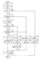
 図3は、ECU200の機能ブロック図である。図3に示した各機能ブロックは、ハードウェアによって実現してもよいし、ソフトウェアによって実現してもよい。 FIG. 3 is a functional block diagram of the ECU 200. Each functional block shown in FIG. 3 may be realized by hardware or software.
 ECU200は、要求トルク算出部210、判定部220,230,260、EHCオフ遅延部250、ブレーキトルク制御部270、EHCオフ遅延解除部280を含む。 ECU 200 includes a required torque calculation unit 210, determination units 220, 230, and 260, an EHC off delay unit 250, a brake torque control unit 270, and an EHC off delay release unit 280.
 要求トルク算出部210は、ストロークセンサ3からのブレーキペダル操作量Bなどに基づいて、ユーザ要求ブレーキトルクTbkmcを算出する。そして、要求トルク算出部210は、ユーザ要求ブレーキトルクTbkmcを超えない範囲で回生要求ブレーキトルクTpbrqを算出する。 The required torque calculation unit 210 calculates the user required brake torque Tbkmc based on the brake pedal operation amount B from the stroke sensor 3 and the like. Then, required torque calculation unit 210 calculates regenerative request brake torque Tpbrq within a range that does not exceed user required brake torque Tbkmc.
 判定部220は、EHCオン/オフ判定を行なう。具体的には、判定部220は、EHCオン状態であるかEHCオフ状態であるのかを判定する。 The determination unit 220 performs EHC on / off determination. Specifically, the determination unit 220 determines whether the EHC is on or the EHC is off.
 判定部230は、EHCオン状態である場合、EHCオフ時WIN越え判定を行なう。EHCオフ時WIN越え判定とは、仮にEHCオフとした時にバッテリ受入電力Pinがバッテリ受入可能電力WINを超えると予測されるか否かを判定する処理である。たとえば、判定部230は、第2MG30がバッテリ受入可能電力WINに相当する回生電力を発生するときの回生ブレーキトルク(以下、「バッテリ許容トルクTwin」という)よりも回生要求ブレーキトルクTpbrqが大きい場合に、「EHCオフ時WIN越え(EHCオフ時にPin>WINとなる)」と予測する。 When the EHC is in an ON state, the determination unit 230 performs a WIN excess determination when the EHC is off. The EHC off WIN excess determination is a process for determining whether or not the battery received power Pin is predicted to exceed the battery acceptable power WIN when the EHC is off. For example, determination unit 230 determines that regeneration request brake torque Tpbrq is larger than regenerative brake torque (hereinafter referred to as “battery allowable torque Twin”) when second MG 30 generates regenerative power corresponding to battery-acceptable power WIN. , It is predicted that “WIN exceeds WIN when EHC is off (Pin> WIN when EHC is off)”.
 EHCオフ遅延部250は、「EHCオフ時WIN越え」と予測された場合に、EHCオフ遅延処理を行なう。EHCオフ遅延処理とは、EHCオフとすることを一時的に遅延させる処理である。たとえば、EHCオフ遅延部250は、EHCオフ遅延を行なうための指令を、図示しないEHC制御部に出力する。これにより、EHCオフとなることが一時的に遅延されることになる。 The EHC off delay unit 250 performs EHC off delay processing when it is predicted that “WIN exceeds WIN when EHC is off”. The EHC off delay process is a process for temporarily delaying the EHC off. For example, the EHC off delay unit 250 outputs a command for performing the EHC off delay to an EHC control unit (not shown). This temporarily delays turning off the EHC.
 判定部260は、EHCオフ遅延処理が行なわれた後、EHCオフとすべき条件が成立したか否かを判定する。具体的には、判定部260は、「EHCオフ予告」の有無および「EHC即オフ要求」の有無を判定する。 The determination unit 260 determines whether or not a condition for turning off the EHC is satisfied after the EHC off delay process is performed. Specifically, determination section 260 determines whether or not “EHC off advance notice” is present and “EHC immediate off request” is present.
 なお、「EHCオフ予告」とは、EHC140が過熱状態となることを回避するために近い将来(所定時間が経過した後)にEHCオフとすることを予告するものである。たとえば、図示しないEHC制御部によって、EHC140の推定温度や消費電力量から所定時間経過後のEHC温度が許容温度を超えると予測された場合に「EHCオフ予告」が出力される。 The “EHC off notice” is a notice that the EHC 140 will be turned off in the near future (after a predetermined time has elapsed) in order to avoid the EHC 140 from being overheated. For example, when an EHC control unit (not shown) predicts that the EHC temperature after a predetermined time has exceeded the allowable temperature from the estimated temperature of the EHC 140 and the amount of power consumption, an “EHC off notice” is output.
 一方、「EHC即オフ要求」とは、即座にEHCオフとすることを要求するものである。たとえば、図示しないEHC制御部によって、EHC140への電力供給が正常に行なえないと判定された場合に「EHC即オフ要求」が出力される。なお、EHC140への電力供給が正常に行なえない場合を例示すると、EHC140に電力を供給するための回路や配線が故障した場合、EHC140の内部破損によりEHC140の電気抵抗が正常値よりも上昇した場合、EHC消費電力Pehcが零となった場合、EHC消費電力Pehcの減少率が基準値を超えた場合、などが挙げられる。 On the other hand, the “EHC immediate turn-off request” is a request to immediately turn off EHC. For example, when the EHC control unit (not shown) determines that the power supply to the EHC 140 cannot be normally performed, an “EHC immediate OFF request” is output. In addition, when the case where the electric power supply to EHC140 cannot be performed normally is illustrated, when the circuit and wiring for supplying electric power to EHC140 fail, the electrical resistance of EHC140 rises from a normal value due to internal damage of EHC140 When the EHC power consumption Pehc becomes zero, the decrease rate of the EHC power consumption Pehc exceeds a reference value, and the like.
 ブレーキトルク制御部270は、ユーザ要求ブレーキトルクTbkmcを実現するように、回生実行ブレーキトルクTpbおよび油圧ブレーキトルクTpbfricを設定する。そして、ブレーキトルク制御部270は、実際の回生ブレーキトルクを回生実行ブレーキトルクTpbにさせるための指令を第2MG30(より正確にはPCU63内のインバータ63)に出力するとともに、実際の油圧ブレーキトルクを油圧ブレーキトルクTpbfricにさせるための指令をECB90に出力する。 The brake torque control unit 270 sets the regeneration execution brake torque Tpb and the hydraulic brake torque Tpbfric so as to realize the user requested brake torque Tbkmc. Then, the brake torque control unit 270 outputs a command for changing the actual regenerative brake torque to the regenerative execution brake torque Tpb to the second MG 30 (more precisely, the inverter 63 in the PCU 63), and the actual hydraulic brake torque. A command for setting the hydraulic brake torque Tpbfric to the ECB 90 is output.
 ブレーキトルク制御部270は、判定部220,230,260による判定結果に応じて、回生実行ブレーキトルクTpbおよび油圧ブレーキトルクTpbfricの設定手法を変更する。 The brake torque control unit 270 changes the setting method of the regeneration execution brake torque Tpb and the hydraulic brake torque Tpbfric according to the determination results by the determination units 220, 230, and 260.
 EHCオフ状態である場合、ブレーキトルク制御部270は、回生要求ブレーキトルクTpbrqにWINガード処理を施した後の値を回生実行ブレーキトルクTpbに設定するとともに、ユーザ要求ブレーキトルクTbkmcから回生実行ブレーキトルクTpbを減じた値(=Tbkmc-Tpb)を油圧ブレーキトルクTpbfricに設定する。 In the EHC off state, the brake torque control unit 270 sets the value after the WIN guard process is performed on the regeneration required brake torque Tpbrq as the regeneration execution brake torque Tpb, and also generates the regeneration execution brake torque from the user requested brake torque Tbkmc. A value obtained by subtracting Tpb (= Tbkmc−Tpb) is set as the hydraulic brake torque Tpbfric.
 ここで、「WINガード処理」とは、回生電力がバッテリ受入可能電力WIN未満となるように回生実行ブレーキトルクTpbの上限を制限する処理である。本実施例では、上述のバッテリ許容トルクTwinよりも回生要求ブレーキトルクTpbrqが小さい場合は回生要求ブレーキトルクTpbrqがそのまま回生実行ブレーキトルクTpbに設定されるが、バッテリ許容トルクTwinよりも回生要求ブレーキトルクTpbrqが大きい場合は回生要求ブレーキトルクTpbrqではなくバッテリ許容トルクTwinが回生実行ブレーキトルクTpbに設定される。これにより、バッテリ受入電力Pinがバッテリ受入可能電力WINを超えること(バッテリ過充電)が防止される。 Here, the “WIN guard process” is a process of limiting the upper limit of the regenerative brake torque Tpb so that the regenerative power is less than the battery acceptable power WIN. In this embodiment, when the regenerative request brake torque Tpbrq is smaller than the above-described battery allowable torque Twin, the regenerative request brake torque Tpbrq is set as the regenerative execution brake torque Tpb as it is, but the regenerative request brake torque is more than the battery allowable torque Twin. When Tpbrq is large, not the regenerative request brake torque Tpbrq but the battery allowable torque Twin is set as the regenerative execution brake torque Tpb. This prevents battery acceptance power Pin from exceeding battery acceptance power WIN (battery overcharge).
 EHCオン状態である場合、「EHCオフ予告」および「EHC即オフ要求」の少なくともいずれかが出力される前は、ブレーキトルク制御部270は、回生実行ブレーキトルクTpbと油圧ブレーキトルクTpbfricとの分担をバッテリ受入可能電力WINおよびEHC消費電力Pehcを用いて決定する。具体的には、ブレーキトルク制御部270は、回生要求ブレーキトルクTpbrqに(WIN+Pehc)ガード処理を施した後の値を回生実行ブレーキトルクTpbに分担させるとともに、ユーザ要求ブレーキトルクTbkmcのうち回生実行ブレーキトルクTpbを超えるトルクを油圧ブレーキトルクTpbfricに分担させる。 In the EHC on state, before at least one of “EHC off advance notice” and “EHC immediate off request” is output, the brake torque control unit 270 shares the regeneration execution brake torque Tpb and the hydraulic brake torque Tpbfric. Is determined using the battery acceptable power WIN and the EHC power consumption Pehc. Specifically, the brake torque control unit 270 shares the value after the (WIN + Pehc) guard process is performed on the regenerative request brake torque Tpbrq with the regenerative execution brake torque Tpb, and the regenerative execution brake among the user requested brake torque Tbkmc. Torque exceeding the torque Tpb is shared by the hydraulic brake torque Tpbfric.
 ここで、「(WIN+Pehc)ガード処理」とは、回生電力がバッテリ受入可能電力WINとEHC消費電力Pehcとの合計値未満となるように回生実行ブレーキトルクTpbの上限を制限する処理である。本実施例では、第2MG30がEHC消費電力の最小値Pehc_minに相当する回生電力を発生するときの回生ブレーキトルク(以下、「EHC許容トルクTehc_min)」という)とバッテリ許容トルクTwinとの合計値よりも回生要求ブレーキトルクTpbrqが小さい場合は回生要求ブレーキトルクTpbrqがそのまま回生要求ブレーキトルクTpbrqに設定されるが、EHC許容トルクTpehc_minとバッテリ許容トルクTwinとの合計値よりも回生要求ブレーキトルクTpbrqが大きい場合はEHC許容トルクTpehc_minとバッテリ許容トルクTwinとの合計値が回生実行ブレーキトルクTpbに設定される。これにより、バッテリ受入可能電力WINを超える回生電力(=WIN+Pehc_min)を発生させることを許容しつつ、バッテリ受入可能電力WINを超える余剰電力をEHC加熱用のエネルギとして有効に利用することができる。これにより、バッテリ70の過充電を抑制しつつ、車両1の運動エネルギを無駄に消費することなく効率的に回収することができる。 Here, the “(WIN + Pehc) guard process” is a process of limiting the upper limit of the regenerative execution brake torque Tpb so that the regenerative power is less than the total value of the battery acceptable power WIN and the EHC power consumption Pehc. In the present embodiment, from the total value of the regenerative brake torque (hereinafter referred to as “EHC permissible torque Tehc_min”) when the second MG 30 generates regenerative power corresponding to the minimum value Pehc_min of EHC power consumption and the permissible battery torque Twin. If the regenerative request brake torque Tpbrq is small, the regenerative request brake torque Tpbrq is set to the regenerative request brake torque Tpbrq as it is, but the regenerative request brake torque Tpbrq is larger than the total value of the EHC allowable torque Tpehc_min and the battery allowable torque Twin. In this case, the total value of the EHC allowable torque Tpehc_min and the battery allowable torque Twin is set as the regeneration execution brake torque Tpb. Accordingly, it is possible to effectively use the surplus power exceeding the battery acceptable power WIN as the energy for EHC heating while allowing the regenerative power (= WIN + Pehc_min) exceeding the battery acceptable power WIN to be generated. Thereby, it is possible to efficiently recover the kinetic energy of the vehicle 1 without wasting it while suppressing overcharge of the battery 70.
 なお、(WIN+Pehc)ガード処理において、EHC消費電力Pehcそのものではなく「EHC消費電力の最小値Pehc_min」を用いているのは、EHC140の状態によってEHC消費電力Pehcが変動することを考慮し、EHC消費電力Pehcが低下してもバッテリ受入電力Pinがバッテリ受入可能電力WINを超えないようにするためである。EHC消費電力の最小値Pehc_minは、監視センサ120からのEHC消費電力Pehcの履歴から設定された値でもよいし、実験等で予め設定しておいた値であってもよい。なお、センサなどで実際のEHC消費電力Pehcを逐一正確に計測できるのであれば、計測したEHC消費電力Pehcそもそもを用いるようにしてもよい。 In the (WIN + Pehc) guard process, the “minimum value of EHC power consumption Pehc_min” is used instead of the EHC power consumption Pehc itself, considering that the EHC power consumption Pehc varies depending on the state of the EHC 140. This is to prevent the battery received power Pin from exceeding the battery acceptable power WIN even when the power Pehc is reduced. The minimum value Pehc_min of EHC power consumption may be a value set from the history of EHC power consumption Pehc from the monitoring sensor 120, or may be a value set in advance through experiments or the like. Note that the measured EHC power consumption Pehc may be used as long as the actual EHC power consumption Pehc can be accurately measured with a sensor or the like.
 EHC状態オンである場合に、EHC140への電力供給を停止すべき緊急度が比較的低い「EHCオフ予告」がなされると、ブレーキトルク制御部270は、回生電力がバッテリ受入可能電力WIN未満となるように回生実行ブレーキトルクTpbを徐々(緩やかに)に低下させるとともに、回生実行ブレーキトルクTpbの低下に応じて油圧ブレーキトルクTpbfricを徐々に増加させる(以下、このような制御を「第1代替制御」ともいう)。たとえば、ブレーキトルク制御部270は、回生実行ブレーキトルクTpbをバッテリ許容トルクTwin未満となるまで所定変化率未満の変化率で徐々に低下させるとともに、油圧ブレーキトルクTpbfricを(Tbkmc-Tpb)とする。これにより、EHCオフ遅延中(EHCオフとなる前)に、回生電力がバッテリ受入可能電力WIN未満となるまで、回生実行ブレーキトルクTpbが油圧ブレーキトルクTpbfricに緩やかに代替される。そのため、ユーザに違和感を与えることなく回生電力をバッテリ受入可能電力WIN未満に低下させることができる。 When the EHC state is on and the “EHC off advance notice” is made with a relatively low degree of urgency to stop power supply to the EHC 140, the brake torque control unit 270 determines that the regenerative power is less than the battery acceptable power WIN. The regenerative execution brake torque Tpb is gradually reduced (gradually) so that the hydraulic brake torque Tpbfric is gradually increased as the regenerative execution brake torque Tpb decreases (hereinafter, such control is referred to as “first alternative”). Also called “control”). For example, the brake torque control unit 270 gradually decreases the regenerative execution brake torque Tpb at a change rate less than a predetermined change rate until it becomes less than the battery allowable torque Twin, and sets the hydraulic brake torque Tpbfric to (Tbkmc−Tpb). Thus, during the EHC off delay (before the EHC is turned off), the regenerative execution brake torque Tpb is gradually replaced with the hydraulic brake torque Tpbfric until the regenerative power becomes less than the battery acceptable power WIN. Therefore, the regenerative power can be reduced below the battery acceptable power WIN without giving the user a sense of incongruity.
 EHCオン状態である場合に、EHC140への電力供給を停止すべき緊急度が比較的高い「EHC即オフ要求」がなされると、ブレーキトルク制御部270は、回生電力が零となるように回生実行ブレーキトルクTpbを所定変化率以上の変化率で即座に低下させる(第2MG30の回生発電を即座に中断する)とともに、油圧ブレーキトルクTpbfricを回生実行ブレーキトルクTpbの低下分だけ増加させる(以下、このような制御を「第2代替制御」ともいう)これにより、回生発電が即座に中断されて回生電力がバッテリ70に供給されなくなるためバッテリ過充電が抑制される。 In the EHC ON state, when an “EHC immediate OFF request” is made with a relatively high degree of urgency to stop power supply to the EHC 140, the brake torque control unit 270 regenerates so that the regenerative power becomes zero. The execution brake torque Tpb is immediately decreased at a change rate equal to or higher than a predetermined change rate (the regenerative power generation of the second MG 30 is immediately interrupted), and the hydraulic brake torque Tpbfric is increased by the decrease in the regenerative execution brake torque Tpb (hereinafter referred to as “regeneration execution brake torque Tpb”). This control is also referred to as “second alternative control”). As a result, regenerative power generation is immediately interrupted and regenerative power is not supplied to the battery 70, so that battery overcharge is suppressed.
 なお、第2代替制御では、回生実行ブレーキトルクTpbを油圧ブレーキトルクTpbfricに急激に代替させるため、実際の油圧ブレーキトルクの増加に遅れが生じユーザに多少の違和感を与えてしまう可能性があるが、緊急度を考慮して、ドライバビリティの悪化抑制よりもバッテリ過充電抑制が優先されることになる。 In the second alternative control, the regenerative execution brake torque Tpb is abruptly replaced with the hydraulic brake torque Tpbfric, which may cause a delay in the actual increase of the hydraulic brake torque and may give the user some discomfort. Considering the degree of urgency, suppression of battery overcharge is given priority over suppression of deterioration of drivability.
 EHCオフ遅延解除部280は、EHCオフ遅延中に、第1代替制御あるいは第2代替制御が完了すると、EHCオフ遅延を解除する処理を行なう。これにより、EHCオフとなることが許容される。 The EHC off delay canceling unit 280 performs processing for canceling the EHC off delay when the first alternative control or the second alternative control is completed during the EHC off delay. This allows the EHC to be turned off.
 図4は、上述のECU200の機能を実現するための処理手順を示すフローチャートである。 FIG. 4 is a flowchart showing a processing procedure for realizing the functions of the ECU 200 described above.
 ステップ(以下、ステップを「S」と略す)10にて、ECU200は、ユーザ要求ブレーキトルクTbkmcを算出する。S20にて、ECU200は、回生要求ブレーキトルクTpbrqを算出する。S30にて、ECU200は、EHCオン状態であるか否かを判定する。 In step (hereinafter, step is abbreviated as “S”) 10, ECU 200 calculates user-requested brake torque Tbkmc. In S20, ECU 200 calculates regeneration request brake torque Tpbrq. In S30, ECU 200 determines whether or not the EHC is on.
 EHCオフ状態である場合(S30にてNO)、ECU200は、S31にて回生要求ブレーキトルクTpbrqにWINガード処理を施した後の値を回生実行ブレーキトルクTpbに設定し、S32にてユーザ要求ブレーキトルクTbkmcから回生実行ブレーキトルクTpbを減じた値(=Tbkmc-Tpb)を油圧ブレーキトルクTpbfricに設定する。 When the ECU is in the EHC off state (NO in S30), ECU 200 sets the value after the WIN guard process is applied to regeneration required brake torque Tpbrq in S31 as regeneration execution brake torque Tpb, and the user requested brake in S32. A value obtained by subtracting the regeneration execution brake torque Tpb from the torque Tbkmc (= Tbkmc−Tpb) is set as the hydraulic brake torque Tpbfric.
 一方、EHCオン状態である場合(S30にてYES)、ECU200は、S40にて「EHCオフ時WIN越え」と予測されるか否かを判定する。 On the other hand, if the EHC is on (YES in S30), ECU 200 determines in S40 whether or not it is predicted that “WIN exceeds EHC when WIN is off”.
 「EHCオフ時WIN越え」と予測される場合(S40にてYES)、ECU200は、S50にてEHCオフ遅延処理を行ない、その後のS60にて「EHCオフ予告」の有無を判定するとともにS70にて「EHC即オフ要求」の有無を判定する。 When it is predicted that “WIN over EHC is off” (YES in S40), ECU 200 performs an EHC off delay process in S50, determines whether or not “EHC off notice” is present in S60, and then proceeds to S70. To determine whether there is an “EHC immediate OFF request”.
 「EHCオフ予告」も「EHC即オフ要求」もなされていない場合(S60およびS70の双方にてNO)、ECU200は、S41にて回生要求ブレーキトルクTpbrqに(WIN+Pehc)ガード処理を施した後の値を回生実行ブレーキトルクTpbに設定し、S42にてユーザ要求ブレーキトルクTbkmcから回生実行ブレーキトルクTpbを減じた値(=Tbkmc-Tpb)を油圧ブレーキトルクTpbfricに設定する。なお、「EHCオフ時WIN越え」と予測されない場合(S40にてNO)にも、S41、S42の処理が行なわれる。 When neither the “EHC off advance notice” nor the “EHC immediate off request” is made (NO in both S60 and S70), the ECU 200 performs the guard process on the regeneration required brake torque Tpbrq in (S41 and SWIN) after applying the (WIN + Pehc) guard process. A value is set to the regenerative execution brake torque Tpb, and a value obtained by subtracting the regenerative execution brake torque Tpb from the user requested brake torque Tbkmc (= Tbkmc−Tpb) is set to the hydraulic brake torque Tpbfric in S42. Note that the processing of S41 and S42 is also performed when it is not predicted that “over WIN when EHC is off” (NO in S40).
 「EHCオフ予告」がなされた場合(S60にてYES)、ECU200は、S61にて前回サイクルの回生実行ブレーキトルクTpbから所定の微小量ΔTを減じた値を今回サイクルの回生実行ブレーキトルクTpbとすることで回生実行ブレーキトルクTpbを所定変化率未満の変化率で徐々に低下させるとともに、S62にて油圧ブレーキトルクTpbfricを(Tbkmc-Tpb)とすることで油圧ブレーキトルクTpbfricを回生実行ブレーキトルクTpbの低下に応じて徐々に増加させる。ECU200は、S63にて回生電力がバッテリ受入可能電力WIN未満であるか否か(回生実行ブレーキトルクTpbがバッテリ許容トルクTwin未満であるか否か)を判定する。ECU200は、回生電力がWIN未満でない場合(S63にてNO)、処理をS61に戻し、回生電力がWIN未満となるまでS61、S62の処理を繰り返す。S61~S63の一連の処理が上述の第1代替制御に相当する。回生電力がWIN未満となった場合(S63にてYES)、ECU200は、処理をS80に移す。 When “EHC off advance notice” is made (YES in S60), ECU 200 determines the value obtained by subtracting a predetermined minute amount ΔT from the regeneration execution brake torque Tpb of the previous cycle as the regeneration execution brake torque Tpb of the current cycle in S61. Thus, the regenerative execution brake torque Tpb is gradually reduced at a change rate less than the predetermined change rate, and the hydraulic brake torque Tpbfric is set to (Tbkmc−Tpb) in S62, so that the hydraulic brake torque Tpbfric is changed to the regenerative execution brake torque Tpb. Increase gradually according to the decrease of. In step S63, the ECU 200 determines whether or not the regenerative power is less than the battery acceptable power WIN (whether or not the regenerative execution brake torque Tpb is less than the battery allowable torque Twin). If the regenerative power is not less than WIN (NO in S63), ECU 200 returns the process to S61 and repeats the processes of S61 and S62 until the regenerative power becomes less than WIN. A series of processes of S61 to S63 corresponds to the first alternative control described above. If the regenerative power is less than WIN (YES in S63), ECU 200 moves the process to S80.
 一方、「EHC即オフ要求」があった場合(S70にてYES)、ECU200は、S71にて回生実行ブレーキトルクTpbを即座に0に低下させることで第2MG30の回生発電を中断するとともに、S72にて油圧ブレーキトルクTpbfricを即座にユーザ要求ブレーキトルクTbkmcに増加させる。S71、S72の処理が上述の第2代替制御に相当する。その後、ECU200は、処理をS80に移す。 On the other hand, when there is an “EHC immediate OFF request” (YES in S70), ECU 200 immediately interrupts regenerative power generation of second MG 30 by reducing regenerative execution brake torque Tpb to 0 in S71, and S72. The hydraulic brake torque Tpbfric is immediately increased to the user requested brake torque Tbkmc. The processes of S71 and S72 correspond to the second alternative control described above. Thereafter, the ECU 200 moves the process to S80.
 S80にて、ECU200は、EHCオフ遅延を解除する。これにより、EHCオフとすることが許容される。 In S80, ECU 200 cancels the EHC off delay. This allows the EHC to be turned off.
 図5は、第1代替制御が行なわれる場合のブレーキトルクおよびEHC状態の時間変化を示す図である。 FIG. 5 is a diagram showing temporal changes in the brake torque and the EHC state when the first alternative control is performed.
 時刻t1にてユーザがブレーキペダルを踏み始めたことに応じてユーザ要求ブレーキトルクTbkmc>0となると、第2MG30の回生発電が開始されて回生実行ブレーキトルクTpbが増加し始める。この時点では、EHCオフ状態であるため回生電力はバッテリ70に供給される。 When the user requested brake torque Tbkmc> 0 in response to the user starting to depress the brake pedal at time t1, the regenerative power generation of the second MG 30 is started and the regenerative execution brake torque Tpb starts to increase. At this time, since the EHC is off, the regenerative power is supplied to the battery 70.
 時刻t2にてEHCオンとなると、回生電力はバッテリ70だけでなくEHC140にも供給され始める。 When EHC is turned on at time t2, the regenerative power starts to be supplied not only to the battery 70 but also to the EHC 140.
 時刻t3にてEHCオフ時WIN越えと予測されると、予め「EHCオフ遅延」がなされる。「EHCオフ予告」がなされる時刻t4までの間は、ユーザ要求ブレーキトルクTbkmcのうち、(Twin+Tpehc_min)未満のトルクが回生実行ブレーキトルクTpbに分担され、残りの(Twin+Tpehc_min)を超えるトルクが油圧ブレーキトルクTpbfricに分担される。 If it is predicted at time t3 that WIN will be exceeded when EHC is off, an “EHC off delay” is made in advance. Until time t4 when the “EHC off notice” is made, of the user requested brake torque Tbkmc, torque less than (Twin + Tpehc_min) is shared by the regeneration execution brake torque Tpb, and the remaining torque exceeding (Twin + Tpehc_min) is hydraulic brake. The torque Tpbfric is shared.
 時刻t4にて「EHCオフ予告」がなされると、第1代替制御が開始される。すなわち、回生電力がバッテリ受入可能電力WIN未満となるように、回生実行ブレーキトルクTpbが徐々に低下されるともに、回生実行ブレーキトルクTpbの低下に応じて油圧ブレーキトルクTpbfricが徐々に増加される。これにより、ユーザに違和感を与えることなく回生電力を低下させることができる。 When “EHC off notice” is made at time t4, the first alternative control is started. That is, the regenerative execution brake torque Tpb is gradually reduced so that the regenerative power becomes less than the battery acceptable power WIN, and the hydraulic brake torque Tpbfric is gradually increased in accordance with the decrease in the regenerative execution brake torque Tpb. Thereby, regenerative electric power can be reduced, without giving a user discomfort.
 時刻t5にて回生電力がバッテリ受入可能電力WIN未満となると(回生実行ブレーキトルクTpbがバッテリ許容トルクTwin未満となると)、「EHCオフ遅延」が解除されEHCオフとされる。これにより、EHC140で消費されていた電力がバッテリ70に供給されて回生電力がすべてバッテリ70に供給されるが、この時点では回生電力がバッテリ受入可能電力WIN未満となっているため、バッテリ過充電が防止される。 When the regenerative power becomes less than the battery acceptable power WIN at time t5 (when the regenerative execution brake torque Tpb becomes less than the battery allowable torque Twin), the “EHC off delay” is canceled and the EHC is turned off. As a result, the power consumed by the EHC 140 is supplied to the battery 70 and all the regenerative power is supplied to the battery 70. At this time, the regenerative power is less than the battery acceptable power WIN, so the battery is overcharged. Is prevented.
 図6は、第2代替制御が行なわれる場合のブレーキトルクおよびEHC状態の時間変化を示す図である。 FIG. 6 is a diagram showing temporal changes in the brake torque and the EHC state when the second alternative control is performed.
 時刻t11にてユーザ要求ブレーキトルクTbkmc>0となると、第2MG30の回生発電が開始されて回生実行ブレーキトルクTpbが増加し始める。 When the user requested brake torque Tbkmc> 0 at time t11, the regenerative power generation of the second MG 30 is started and the regenerative execution brake torque Tpb starts to increase.
 時刻t12にてEHCオンとなると、回生電力はバッテリ70だけでなくEHC140にも供給され始める。時刻t13にて「EHCオフ時WIN越え」と予測されると、予め「EHCオフ遅延」がなされる。「EHC即オフ要求」がなされる時刻t14までの間は、ユーザ要求ブレーキトルクTbkmcのうち、(Twin+Tpehc_min)未満のトルクが回生実行ブレーキトルクTpbに分担され、残りの(Twin+Tpehc_min)を超えるトルクが油圧ブレーキトルクTpbfricに分担される。 When EHC is turned on at time t12, regenerative power starts to be supplied not only to the battery 70 but also to the EHC 140. If it is predicted at time t13 that “over WIN when EHC is off”, “EHC off delay” is made in advance. Until time t14 when the “EHC immediate OFF request” is made, the torque less than (Twin + Tpehc_min) of the user-requested brake torque Tbkmc is shared with the regeneration execution brake torque Tpb, and the torque exceeding the remaining (Twin + Tpehc_min) is hydraulic. The brake torque Tpbfric is shared.
 時刻t14にて「EHC即オフ要求」がなされると、第2代替制御が実行される。すなわち、回生発電が中断されて回生実行ブレーキトルクTpbが即座に0に低下されるとともに、油圧ブレーキトルクTpbfricが即座にユーザ要求ブレーキトルクTbkmcに増加される。これにより、EHC140に電力を供給できないような故障が発生した場合であっても、バッテリ過充電が即座に抑制されることになる。 When “EHC immediate OFF request” is made at time t14, the second alternative control is executed. That is, the regenerative power generation is interrupted, the regenerative execution brake torque Tpb is immediately reduced to 0, and the hydraulic brake torque Tpbfric is immediately increased to the user requested brake torque Tbkmc. As a result, even if a failure occurs in which power cannot be supplied to the EHC 140, battery overcharge is immediately suppressed.
 第2代替制御が完了する時刻t15にて「EHCオフ遅延」が解除されEHCオフとされる。この時点では既に回生発電が中断されているため、EHCオフとすることによって過剰な電力がバッテリ70に供給されることはない。 At time t15 when the second substitution control is completed, the “EHC off delay” is canceled and the EHC is turned off. Since regenerative power generation is already interrupted at this point, excessive power is not supplied to the battery 70 by turning off the EHC.
 以上のように、本実施例によるECU200は、EHCオン状態で車両1が回生制動している場合(回生電力をバッテリ70およびEHC140の双方に供給している場合)に、EHCオフとすべき事情が生じたときは、EHCオフとすることを一時的に遅延させた上で回生ブレーキを油圧ブレーキに代替させる。そして、ECU200は、回生ブレーキから油圧ブレーキへの代替が完了した後に、EHCオフ遅延を解除する(EHCオフとすることを許容する)。これにより、第2MG30の回生電力を有効に利用しつつバッテリ過充電抑制とドライバビリティ悪化抑制とを両立することができる。 As described above, the ECU 200 according to the present embodiment should turn off the EHC when the vehicle 1 is performing regenerative braking while the EHC is on (when regenerative power is supplied to both the battery 70 and the EHC 140). When this occurs, the regenerative brake is replaced with a hydraulic brake after delaying EHC off temporarily. Then, after the replacement from the regenerative brake to the hydraulic brake is completed, ECU 200 cancels the EHC off delay (allows EHC off). Thereby, it is possible to achieve both battery overcharge suppression and drivability deterioration suppression while effectively using the regenerative power of the second MG 30.
 今回開示された実施例はすべての点で例示であって制限的なものではないと考えられるべきである。本発明の範囲は上記した説明ではなくて請求の範囲によって示され、請求の範囲と均等の意味および範囲内でのすべての変更が含まれることが意図される。 The embodiment disclosed this time should be considered as illustrative in all points and not restrictive. The scope of the present invention is defined by the terms of the claims, rather than the description above, and is intended to include any modifications within the scope and meaning equivalent to the terms of the claims.
 1 車両、2 ポジションセンサ、3 ストロークセンサ、10 エンジン、20 第1MG、30 第2MG、40 動力分割装置、50 減速機、60 PCU、61 コンバータ、62,63 インバータ、70 バッテリ、80 駆動輪、100 切替装置、120 監視センサ、130 排気通路、140 EHC、200 ECH、210 要求トルク算出部、220,230,260 判定部、250 EHCオフ遅延部、270 ブレーキトルク制御部、280 EHCオフ遅延解除部、NL1 負極線、NLehc 負極分岐線、PL1,PL2 正極線、PLehc 正極分岐線、R1,R2 リレー。 1 vehicle, 2 position sensor, 3 stroke sensor, 10 engine, 20 1st MG, 30 2nd MG, 40 power split device, 50 speed reducer, 60 PCU, 61 converter, 62, 63 inverter, 70 battery, 80 drive wheels, 100 Switching device, 120 monitoring sensor, 130 exhaust passage, 140 EHC, 200 ECH, 210 required torque calculation unit, 220, 230, 260 determination unit, 250 EHC off delay unit, 270 brake torque control unit, 280 EHC off delay release unit, NL1 negative line, NLehc negative branch line, PL1, PL2 positive line, PLehc positive branch line, R1, R2 relay.

Claims (8)

  1.  駆動輪に連結されたモータ(30)と、
     前記モータとの間で電力を授受する蓄電装置(70)と、
     エンジン(10)と、
     前記モータと前記蓄電装置とを接続する電力線から供給される電力で加熱される、前記エンジンの排気を浄化する触媒装置(140)と、
     前記駆動輪に油圧ブレーキトルクを作用させる油圧ブレーキ装置(90)と、
     前記モータおよび前記油圧ブレーキ装置を制御する制御装置(200)とを備え、
     前記制御装置は、前記モータの回生発電によって生じた回生電力を前記蓄電装置および前記触媒装置の双方に供給している場合、前記触媒装置への電力供給を停止すべきであるという停止条件が成立したときに、前記回生発電による回生ブレーキトルクの少なくとも一部を前記油圧ブレーキトルクに代替させる、車両。
    A motor (30) coupled to the drive wheels;
    A power storage device (70) for transferring power to and from the motor;
    An engine (10);
    A catalyst device (140) for purifying exhaust of the engine, heated by electric power supplied from a power line connecting the motor and the power storage device;
    A hydraulic brake device (90) for applying hydraulic brake torque to the drive wheel;
    A control device (200) for controlling the motor and the hydraulic brake device,
    When the control device supplies regenerative power generated by regenerative power generation of the motor to both the power storage device and the catalyst device, a stop condition is established that power supply to the catalyst device should be stopped When this is done, the vehicle replaces at least a part of the regenerative brake torque generated by the regenerative power generation with the hydraulic brake torque.
  2.  前記停止条件は、前記触媒装置への電力供給を近い将来に停止すべきであるという第1停止条件を含み、
     前記制御装置は、前記回生電力を前記双方に供給している場合、前記第1停止条件が成立したときに、前記触媒装置への電力供給が停止される前に、前記回生ブレーキトルクを所定変化率未満の変化率で徐々に低下させるとともに前記油圧ブレーキトルクを前記回生ブレーキトルクの低下に応じて徐々に増加させる第1代替制御を実行する、請求項1に記載の車両。
    The stop condition includes a first stop condition that power supply to the catalyst device should be stopped in the near future,
    When the control device is supplying the regenerative power to both of them, the regenerative brake torque is changed by a predetermined amount before the power supply to the catalyst device is stopped when the first stop condition is satisfied. 2. The vehicle according to claim 1, wherein a first alternative control is executed in which the hydraulic brake torque is gradually decreased at a change rate less than a rate and the hydraulic brake torque is gradually increased in accordance with a decrease in the regenerative brake torque.
  3.  前記制御装置は、前記回生電力を前記双方に供給している場合、前記第1停止条件が成立する前は、前記回生電力が前記蓄電装置の受入可能電力と前記触媒装置の消費電力との合計値未満となるように前記回生ブレーキトルクを制御し、
     前記第1代替制御は、前記回生電力が前記蓄電装置の受入可能電力未満となるまで前記回生ブレーキトルクを低下させるとともに前記油圧ブレーキトルクを前記回生ブレーキトルクの低下分だけ増加させる制御である、請求項2に記載の車両。
    When the control device supplies the regenerative power to both, the regenerative power is the sum of the receivable power of the power storage device and the power consumption of the catalyst device before the first stop condition is satisfied. The regenerative brake torque is controlled to be less than the value,
    The first alternative control is a control for decreasing the regenerative brake torque and increasing the hydraulic brake torque by a decrease in the regenerative brake torque until the regenerative power becomes less than the receivable power of the power storage device. Item 4. The vehicle according to item 2.
  4.  前記停止条件は、前記触媒装置への電力供給を即座に停止すべきであるという第2停止条件を含み、
     前記制御装置は、前記回生電力を前記双方に供給している場合、前記第2停止条件が成立したときに、前記回生ブレーキトルクを所定変化率以上の変化率で即座に低下させるとともに前記油圧ブレーキトルクを前記回生ブレーキトルクの低下に応じて増加させる第2代替制御を実行する、請求項1に記載の車両。
    The stop condition includes a second stop condition that power supply to the catalyst device should be stopped immediately,
    In the case where the regenerative power is supplied to both the control device, the control device immediately reduces the regenerative brake torque at a change rate equal to or higher than a predetermined change rate and satisfies the hydraulic brake when the second stop condition is satisfied. 2. The vehicle according to claim 1, wherein second alternative control for increasing torque according to a decrease in the regenerative brake torque is executed.
  5.  前記制御装置は、前記回生電力を前記双方に供給している場合、前記第2停止条件が成立する前は、前記回生電力が前記蓄電装置の受入可能電力と前記触媒装置の消費電力との合計値未満となるように前記回生ブレーキトルクを制御し、
     前記第2代替制御は、前記回生電力が零となるまで前記回生ブレーキトルクを低下させるとともに前記油圧ブレーキトルクを前記回生ブレーキトルクの低下分だけ増加させる制御である、請求項4に記載の車両。
    When the control device supplies the regenerative power to both, the regenerative power is the sum of the receivable power of the power storage device and the power consumption of the catalyst device before the second stop condition is satisfied. The regenerative brake torque is controlled to be less than the value,
    5. The vehicle according to claim 4, wherein the second alternative control is a control for decreasing the regenerative brake torque and increasing the hydraulic brake torque by a decrease of the regenerative brake torque until the regenerative power becomes zero.
  6.  前記制御装置は、前記回生電力を前記双方に供給している場合、前記停止条件が成立する前は、前記回生ブレーキトルクと前記油圧ブレーキトルクとの分担を前記蓄電装置の受入可能電力および前記触媒装置の消費電力を用いて決定する、請求項1に記載の車両。 When the regenerative power is supplied to both of the control devices, the control device shares the regenerative brake torque with the hydraulic brake torque before the stop condition is established, and the receivable power of the power storage device and the catalyst The vehicle according to claim 1, wherein the vehicle is determined using power consumption of the device.
  7.  前記制御装置は、前記回生電力が前記蓄電装置の受入可能電力と前記触媒装置の消費電力との合計値未満となるように前記回生ブレーキトルクを決定し、ユーザによる要求ブレーキトルクのうち前記回生ブレーキトルクを超えるトルクを前記油圧ブレーキトルクに分担させる、請求項6に記載の車両。 The control device determines the regenerative brake torque so that the regenerative power is less than a total value of the receivable power of the power storage device and the power consumption of the catalyst device, and the regenerative brake is included in the user-requested brake torque. The vehicle according to claim 6, wherein a torque exceeding a torque is shared by the hydraulic brake torque.
  8.  車両の制御方法であって、
     前記車両は、
     駆動輪に連結されたモータ(30)と、
     前記モータとの間で電力を授受する蓄電装置(70)と、
     エンジン(10)と、
     前記モータと前記蓄電装置とを接続する電力線から供給される電力で加熱される、前記エンジンの排気を浄化する触媒装置(140)と、
     前記駆動輪に油圧ブレーキトルクを作用させる油圧ブレーキ装置(90)と、
     前記モータおよび前記油圧ブレーキ装置を制御する制御装置(200)とを備え、
     前記制御方法は、
     前記モータの回生発電によって生じた回生電力を前記蓄電装置および前記触媒装置の双方に供給しているか否かを判定するステップと、
     前記回生電力を前記双方に供給している場合、前記触媒装置への電力供給を停止すべき条件が成立したときに、前記回生発電による回生ブレーキトルクの少なくとも一部を前記油圧ブレーキトルクに代替させるステップとを含む、車両の制御方法。
    A vehicle control method comprising:
    The vehicle is
    A motor (30) coupled to the drive wheels;
    A power storage device (70) for transferring power to and from the motor;
    An engine (10);
    A catalyst device (140) for purifying exhaust of the engine, heated by electric power supplied from a power line connecting the motor and the power storage device;
    A hydraulic brake device (90) for applying hydraulic brake torque to the drive wheel;
    A control device (200) for controlling the motor and the hydraulic brake device,
    The control method is:
    Determining whether regenerative power generated by regenerative power generation of the motor is supplied to both the power storage device and the catalyst device;
    When the regenerative electric power is supplied to both of them, at least a part of the regenerative brake torque generated by the regenerative power generation is replaced with the hydraulic brake torque when a condition for stopping the power supply to the catalyst device is satisfied. And a vehicle control method.
PCT/JP2011/077025 2011-11-24 2011-11-24 Vehicle, and vehicle control method WO2013076836A1 (en)

Priority Applications (5)

Application Number Priority Date Filing Date Title
EP11876292.1A EP2783936B1 (en) 2011-11-24 2011-11-24 Vehicle, and vehicle control method
JP2013545711A JP5761371B2 (en) 2011-11-24 2011-11-24 Vehicle and vehicle control method
US14/357,646 US9469293B2 (en) 2011-11-24 2011-11-24 Vehicle and control method for vehicle
CN201180074996.5A CN103946093B (en) 2011-11-24 2011-11-24 Vehicle and the control method of vehicle
PCT/JP2011/077025 WO2013076836A1 (en) 2011-11-24 2011-11-24 Vehicle, and vehicle control method

Applications Claiming Priority (1)

Application Number Priority Date Filing Date Title
PCT/JP2011/077025 WO2013076836A1 (en) 2011-11-24 2011-11-24 Vehicle, and vehicle control method

Publications (1)

Publication Number Publication Date
WO2013076836A1 true WO2013076836A1 (en) 2013-05-30

Family

ID=48469315

Family Applications (1)

Application Number Title Priority Date Filing Date
PCT/JP2011/077025 WO2013076836A1 (en) 2011-11-24 2011-11-24 Vehicle, and vehicle control method

Country Status (5)

Country Link
US (1) US9469293B2 (en)
EP (1) EP2783936B1 (en)
JP (1) JP5761371B2 (en)
CN (1) CN103946093B (en)
WO (1) WO2013076836A1 (en)

Cited By (5)

* Cited by examiner, † Cited by third party
Publication number Priority date Publication date Assignee Title
CN104234797A (en) * 2013-06-19 2014-12-24 上海汽车集团股份有限公司 Catalyst heating control method used for optimizing emissions of plug-in type hybrid electric vehicles
JP2015041653A (en) * 2013-08-21 2015-03-02 株式会社ディスコ Working apparatus
US20160121727A1 (en) * 2014-10-30 2016-05-05 Hyundai Motor Company Braking control method for eco-friendly vehicle
JP2020028182A (en) * 2018-08-10 2020-02-20 株式会社Subaru Charging system
JP2021054155A (en) * 2019-09-27 2021-04-08 いすゞ自動車株式会社 Hybrid vehicle power supply system

Families Citing this family (7)

* Cited by examiner, † Cited by third party
Publication number Priority date Publication date Assignee Title
JP6376169B2 (en) * 2016-04-20 2018-08-22 トヨタ自動車株式会社 Hybrid vehicle
DE102016218858A1 (en) 2016-09-29 2018-03-29 Audi Ag Time-optimized particle filter regeneration in hybrid vehicles
KR102304853B1 (en) * 2017-07-31 2021-09-27 현대자동차주식회사 Hybrid vehicle and method of controlling electric motor of the same
JP6958484B2 (en) * 2018-05-29 2021-11-02 トヨタ自動車株式会社 Vehicle control device
KR20200115820A (en) * 2019-03-27 2020-10-08 현대자동차주식회사 Hybrid vehicle and method of braking control for the same
FR3100511B1 (en) * 2019-09-05 2022-05-20 Continental Automotive Gmbh Control computer for a traction chain of a hybrid vehicle
DE102019124788A1 (en) * 2019-09-16 2020-08-20 Audi Ag Method for operating a drive device for a motor vehicle and a corresponding drive device

Citations (8)

* Cited by examiner, † Cited by third party
Publication number Priority date Publication date Assignee Title
JPH10238381A (en) 1997-02-25 1998-09-08 Denso Corp Hybrid vehicle control device
JPH114503A (en) * 1997-06-10 1999-01-06 Toyota Motor Corp Brake device for car
JP2003127721A (en) * 2001-10-25 2003-05-08 Toyota Motor Corp Braking controller for vehicle
JP2004245135A (en) 2003-02-14 2004-09-02 Mitsubishi Motors Corp Power controller for vehicle
JP2005002989A (en) 2003-05-21 2005-01-06 Toyota Motor Corp Power output device, its control method, and automobile
JP2009189921A (en) 2008-02-13 2009-08-27 Toyota Motor Corp Current flow control system for use in catalyst device heated by current flow
JP2009214703A (en) 2008-03-11 2009-09-24 Nissan Motor Co Ltd Control device of hybrid vehicle
JP2011167030A (en) 2010-02-15 2011-08-25 Toyota Motor Corp Device for control of electric vehicle

Family Cites Families (8)

* Cited by examiner, † Cited by third party
Publication number Priority date Publication date Assignee Title
JP3573206B2 (en) * 2002-03-12 2004-10-06 トヨタ自動車株式会社 Vehicle control device
JP2004360289A (en) * 2003-06-04 2004-12-24 Bunka Shutter Co Ltd Opening and closing device
JP2006174543A (en) * 2004-12-13 2006-06-29 Honda Motor Co Ltd Regenerative power controller in hybrid vehicle
JP4175370B2 (en) * 2006-01-13 2008-11-05 トヨタ自動車株式会社 Hybrid vehicle and control method thereof
US8630759B2 (en) * 2009-11-20 2014-01-14 GM Global Technology Operations LLC Control of regenerative braking in a hybrid vehicle
DE102010004436A1 (en) 2010-01-13 2011-07-14 Bayerische Motoren Werke Aktiengesellschaft, 80809 Motor vehicle, has temporary active electromotive propulsion produced in coasting, where rate of effective brake torque of running speed of vehicle is defined based on electronic control unit
CN103370245B (en) * 2011-02-16 2016-03-09 丰田自动车株式会社 The control method of vehicle and vehicle
JP5622055B2 (en) * 2012-07-02 2014-11-12 株式会社デンソー Control device for hybrid vehicle

Patent Citations (8)

* Cited by examiner, † Cited by third party
Publication number Priority date Publication date Assignee Title
JPH10238381A (en) 1997-02-25 1998-09-08 Denso Corp Hybrid vehicle control device
JPH114503A (en) * 1997-06-10 1999-01-06 Toyota Motor Corp Brake device for car
JP2003127721A (en) * 2001-10-25 2003-05-08 Toyota Motor Corp Braking controller for vehicle
JP2004245135A (en) 2003-02-14 2004-09-02 Mitsubishi Motors Corp Power controller for vehicle
JP2005002989A (en) 2003-05-21 2005-01-06 Toyota Motor Corp Power output device, its control method, and automobile
JP2009189921A (en) 2008-02-13 2009-08-27 Toyota Motor Corp Current flow control system for use in catalyst device heated by current flow
JP2009214703A (en) 2008-03-11 2009-09-24 Nissan Motor Co Ltd Control device of hybrid vehicle
JP2011167030A (en) 2010-02-15 2011-08-25 Toyota Motor Corp Device for control of electric vehicle

Cited By (8)

* Cited by examiner, † Cited by third party
Publication number Priority date Publication date Assignee Title
CN104234797A (en) * 2013-06-19 2014-12-24 上海汽车集团股份有限公司 Catalyst heating control method used for optimizing emissions of plug-in type hybrid electric vehicles
CN104234797B (en) * 2013-06-19 2016-11-16 上海汽车集团股份有限公司 For optimizing the catalyst converter method for heating and controlling of plug-in hybrid-power automobile discharge
JP2015041653A (en) * 2013-08-21 2015-03-02 株式会社ディスコ Working apparatus
US20160121727A1 (en) * 2014-10-30 2016-05-05 Hyundai Motor Company Braking control method for eco-friendly vehicle
US9834096B2 (en) * 2014-10-30 2017-12-05 Hyundai Motor Company Braking control method for eco-friendly vehicle
JP2020028182A (en) * 2018-08-10 2020-02-20 株式会社Subaru Charging system
JP7161340B2 (en) 2018-08-10 2022-10-26 株式会社Subaru charging system
JP2021054155A (en) * 2019-09-27 2021-04-08 いすゞ自動車株式会社 Hybrid vehicle power supply system

Also Published As

Publication number Publication date
JPWO2013076836A1 (en) 2015-04-27
EP2783936A1 (en) 2014-10-01
US9469293B2 (en) 2016-10-18
EP2783936A4 (en) 2016-03-23
JP5761371B2 (en) 2015-08-12
CN103946093B (en) 2016-08-24
US20150057857A1 (en) 2015-02-26
CN103946093A (en) 2014-07-23
EP2783936B1 (en) 2018-05-30

Similar Documents

Publication Publication Date Title
JP5761371B2 (en) Vehicle and vehicle control method
KR101622525B1 (en) Hybrid vehicle
JP5310959B2 (en) Vehicle charging device
US9074509B2 (en) Control apparatus for vehicle
JP5716681B2 (en) Vehicle and vehicle control method
JP5333573B2 (en) Vehicle control apparatus and control method
JP2007221886A (en) Charging/discharging controller of secondary battery
JP5928326B2 (en) Electric vehicle and control method of electric vehicle
JP5729475B2 (en) Vehicle and vehicle control method
JP5803507B2 (en) Hybrid vehicle control device and hybrid vehicle
JP2006280161A (en) Regenerative controller for hybrid electric vehicle
JPWO2012111087A1 (en) Electric vehicle and control method thereof
JP5923906B2 (en) Vehicle and vehicle control method
JP2010115035A (en) Battery protection device
JP6798437B2 (en) Electric vehicle
JP2010215106A (en) Control system for hybrid vehicle
JP5949365B2 (en) Power system
JP5545372B2 (en) Vehicle control apparatus and control method
JP5641145B2 (en) Vehicle and vehicle control method
JP2015013517A (en) Vehicle controller
JP2021138242A (en) Hybrid vehicle and method for controlling waste of electricity thereof

Legal Events

Date Code Title Description
121 Ep: the epo has been informed by wipo that ep was designated in this application

Ref document number: 11876292

Country of ref document: EP

Kind code of ref document: A1

ENP Entry into the national phase

Ref document number: 2013545711

Country of ref document: JP

Kind code of ref document: A

WWE Wipo information: entry into national phase

Ref document number: 14357646

Country of ref document: US

WWE Wipo information: entry into national phase

Ref document number: 2011876292

Country of ref document: EP

NENP Non-entry into the national phase

Ref country code: DE