WO2013069671A1 - 電力管理装置、電力管理装置の制御方法および電力管理装置の制御プログラム - Google Patents
電力管理装置、電力管理装置の制御方法および電力管理装置の制御プログラム Download PDFInfo
- Publication number
- WO2013069671A1 WO2013069671A1 PCT/JP2012/078815 JP2012078815W WO2013069671A1 WO 2013069671 A1 WO2013069671 A1 WO 2013069671A1 JP 2012078815 W JP2012078815 W JP 2012078815W WO 2013069671 A1 WO2013069671 A1 WO 2013069671A1
- Authority
- WO
- WIPO (PCT)
- Prior art keywords
- information
- power consumption
- power
- group
- measurement
- Prior art date
Links
Images


Classifications
-
- G—PHYSICS
- G01—MEASURING; TESTING
- G01R—MEASURING ELECTRIC VARIABLES; MEASURING MAGNETIC VARIABLES
- G01R21/00—Arrangements for measuring electric power or power factor
-
- G—PHYSICS
- G01—MEASURING; TESTING
- G01D—MEASURING NOT SPECIALLY ADAPTED FOR A SPECIFIC VARIABLE; ARRANGEMENTS FOR MEASURING TWO OR MORE VARIABLES NOT COVERED IN A SINGLE OTHER SUBCLASS; TARIFF METERING APPARATUS; MEASURING OR TESTING NOT OTHERWISE PROVIDED FOR
- G01D4/00—Tariff metering apparatus
- G01D4/002—Remote reading of utility meters
-
- G—PHYSICS
- G01—MEASURING; TESTING
- G01D—MEASURING NOT SPECIALLY ADAPTED FOR A SPECIFIC VARIABLE; ARRANGEMENTS FOR MEASURING TWO OR MORE VARIABLES NOT COVERED IN A SINGLE OTHER SUBCLASS; TARIFF METERING APPARATUS; MEASURING OR TESTING NOT OTHERWISE PROVIDED FOR
- G01D2204/00—Indexing scheme relating to details of tariff-metering apparatus
- G01D2204/10—Analysing; Displaying
- G01D2204/14—Displaying of utility usage with respect to time, e.g. for monitoring evolution of usage or with respect to weather conditions
-
- G—PHYSICS
- G01—MEASURING; TESTING
- G01R—MEASURING ELECTRIC VARIABLES; MEASURING MAGNETIC VARIABLES
- G01R22/00—Arrangements for measuring time integral of electric power or current, e.g. electricity meters
- G01R22/06—Arrangements for measuring time integral of electric power or current, e.g. electricity meters by electronic methods
- G01R22/10—Arrangements for measuring time integral of electric power or current, e.g. electricity meters by electronic methods using digital techniques
-
- Y—GENERAL TAGGING OF NEW TECHNOLOGICAL DEVELOPMENTS; GENERAL TAGGING OF CROSS-SECTIONAL TECHNOLOGIES SPANNING OVER SEVERAL SECTIONS OF THE IPC; TECHNICAL SUBJECTS COVERED BY FORMER USPC CROSS-REFERENCE ART COLLECTIONS [XRACs] AND DIGESTS
- Y02—TECHNOLOGIES OR APPLICATIONS FOR MITIGATION OR ADAPTATION AGAINST CLIMATE CHANGE
- Y02B—CLIMATE CHANGE MITIGATION TECHNOLOGIES RELATED TO BUILDINGS, e.g. HOUSING, HOUSE APPLIANCES OR RELATED END-USER APPLICATIONS
- Y02B70/00—Technologies for an efficient end-user side electric power management and consumption
- Y02B70/30—Systems integrating technologies related to power network operation and communication or information technologies for improving the carbon footprint of the management of residential or tertiary loads, i.e. smart grids as climate change mitigation technology in the buildings sector, including also the last stages of power distribution and the control, monitoring or operating management systems at local level
-
- Y—GENERAL TAGGING OF NEW TECHNOLOGICAL DEVELOPMENTS; GENERAL TAGGING OF CROSS-SECTIONAL TECHNOLOGIES SPANNING OVER SEVERAL SECTIONS OF THE IPC; TECHNICAL SUBJECTS COVERED BY FORMER USPC CROSS-REFERENCE ART COLLECTIONS [XRACs] AND DIGESTS
- Y02—TECHNOLOGIES OR APPLICATIONS FOR MITIGATION OR ADAPTATION AGAINST CLIMATE CHANGE
- Y02B—CLIMATE CHANGE MITIGATION TECHNOLOGIES RELATED TO BUILDINGS, e.g. HOUSING, HOUSE APPLIANCES OR RELATED END-USER APPLICATIONS
- Y02B90/00—Enabling technologies or technologies with a potential or indirect contribution to GHG emissions mitigation
- Y02B90/20—Smart grids as enabling technology in buildings sector
-
- Y—GENERAL TAGGING OF NEW TECHNOLOGICAL DEVELOPMENTS; GENERAL TAGGING OF CROSS-SECTIONAL TECHNOLOGIES SPANNING OVER SEVERAL SECTIONS OF THE IPC; TECHNICAL SUBJECTS COVERED BY FORMER USPC CROSS-REFERENCE ART COLLECTIONS [XRACs] AND DIGESTS
- Y04—INFORMATION OR COMMUNICATION TECHNOLOGIES HAVING AN IMPACT ON OTHER TECHNOLOGY AREAS
- Y04S—SYSTEMS INTEGRATING TECHNOLOGIES RELATED TO POWER NETWORK OPERATION, COMMUNICATION OR INFORMATION TECHNOLOGIES FOR IMPROVING THE ELECTRICAL POWER GENERATION, TRANSMISSION, DISTRIBUTION, MANAGEMENT OR USAGE, i.e. SMART GRIDS
- Y04S20/00—Management or operation of end-user stationary applications or the last stages of power distribution; Controlling, monitoring or operating thereof
- Y04S20/20—End-user application control systems
- Y04S20/242—Home appliances
-
- Y—GENERAL TAGGING OF NEW TECHNOLOGICAL DEVELOPMENTS; GENERAL TAGGING OF CROSS-SECTIONAL TECHNOLOGIES SPANNING OVER SEVERAL SECTIONS OF THE IPC; TECHNICAL SUBJECTS COVERED BY FORMER USPC CROSS-REFERENCE ART COLLECTIONS [XRACs] AND DIGESTS
- Y04—INFORMATION OR COMMUNICATION TECHNOLOGIES HAVING AN IMPACT ON OTHER TECHNOLOGY AREAS
- Y04S—SYSTEMS INTEGRATING TECHNOLOGIES RELATED TO POWER NETWORK OPERATION, COMMUNICATION OR INFORMATION TECHNOLOGIES FOR IMPROVING THE ELECTRICAL POWER GENERATION, TRANSMISSION, DISTRIBUTION, MANAGEMENT OR USAGE, i.e. SMART GRIDS
- Y04S20/00—Management or operation of end-user stationary applications or the last stages of power distribution; Controlling, monitoring or operating thereof
- Y04S20/30—Smart metering, e.g. specially adapted for remote reading
Definitions
- the present invention relates to a power management apparatus that manages power information related to power consumption in at least one electrical device, a control method for the power management apparatus, and a control program.
- Patent Document 1 In order to realize energy saving, it is necessary to first measure the power consumption state of electrical equipment.
- Patent Document 1 the power management system disclosed in Japanese Patent Application Laid-Open No. 2011-120428 (Patent Document 1) measures power for each branch breaker, and displays a list of power usage by grouping the results. It is shown.
- Patent Document 1 power measurement is performed for each branch breaker, and data acquisition and grouping according to the installation state of the branch breaker are performed. Therefore, it is not possible to acquire power consumption data for each electrical device or the like and group and display the information on the power consumption state useful for the user.
- the present invention has been made to solve such a problem, and an object of the present invention is to provide a power management apparatus capable of presenting information related to a state of power consumption useful for a user regarding a plurality of electrical devices. It is another object of the present invention to provide a control method and a control program for a power management apparatus.
- a power management apparatus includes an acquisition unit that acquires information about power consumption from a plurality of electrical devices, a display unit, and information about the power consumption of the plurality of electrical devices acquired via the acquisition unit. And a controller for displaying.
- a plurality of attribute information is set in advance in association with each electric device, and the controller executes a grouping of a plurality of hierarchies based on the plurality of attribute information for each of the plurality of electric devices, and classifies by grouping of the plurality of hierarchies. For each group, information regarding the power consumption of the electrical equipment belonging to the group is displayed.
- the controller can accept an instruction to display information on the power consumption of each electric device belonging to each group, and when the instruction is accepted, the upper-level group of the plurality of electric devices For the electric devices belonging to the above, information on the power consumption of each electric device is displayed.
- the instruction is a selection instruction for each group
- the controller expands for each group, and information on each power consumption for each electric device belonging to each group Can be displayed on the display unit, and information on the power consumption of each electrical device belonging to the selected group is displayed in the display area of the display unit, and displayed in the display area according to the operation instructions.
- Information regarding the power consumption of each electric device belonging to the group that is not included is displayed in the display area of the display unit.
- the information related to power consumption is at least one of power consumption and power consumption related to a plurality of electrical devices, and the controller uses the power consumption and power consumption in an order according to a predetermined method for each electrical device belonging to the selected group. Display at least one of the quantities.
- the information related to power consumption is at least one of power consumption and power consumption related to a plurality of electrical devices, and priority is assigned in advance to at least one attribute information of the plurality of attribute information. For each group classified by the grouping of a plurality of hierarchies according to the priority assigned to the attribute information, at least one of the total power consumption and power consumption of the electric devices belonging to the group is displayed.
- the controller displays, for each group classified by the grouping of a plurality of hierarchies, an object indicating information related to the power consumption of the electrical equipment belonging to the group provided so as to be selectable.
- the object is displayed in a form in which objects corresponding to the number of electrical devices belonging to each group are overlapped.
- a control method of a power management apparatus includes a step of acquiring information related to power consumption from a plurality of electrical devices, and a step of displaying information on the acquired power consumption related to a plurality of electrical devices on a display unit.
- a plurality of attribute information is set in association with each electrical device in advance, and the step of displaying the plurality of electrical devices includes a step of performing grouping of a plurality of layers based on the plurality of attribute information, respectively. Displaying information relating to the power consumption of the electrical equipment belonging to the group for each group classified by the grouping of the hierarchy.
- a control program for a power management apparatus is a control program for a power management apparatus having a display unit, the computer acquiring information about power consumption from a plurality of electrical devices, and a plurality of acquired And a step of displaying information on power consumption related to the electric device on the display unit.
- Each electric device has a plurality of pieces of attribute information associated with it in advance, and the step of displaying includes a plurality of steps for the plurality of electric devices.
- a process including a step of performing grouping of a plurality of hierarchies based on each attribute information, and a step of displaying information on the power consumption of electric devices belonging to the group for each group classified by the grouping of the multi-hierarchy. Let it run.
- a management system that manages measurement information related to power consumption in at least one electrical device.
- the management system includes a first storage unit that stores, in a time series, measurement information regarding power consumption in each electrical device, which is transmitted from each measurement device associated with each electrical device, and the measurement device and the electrical Second storage means for storing history information related to association with the device, and in response to selection of the electric device, measurement information corresponding to the selected electric device among the measurement information stored separately for each measuring instrument.
- Information output means for outputting power information about the selected electrical device by extraction.
- the second storage means stores, as history information, the time when the association with the measuring device is validated and information for identifying the associated measuring device separately for each electric device.
- the second storage means stores information for identifying the latest associated measuring instrument as history information, separately for each electrical device.
- the management system further includes selection accepting means for providing a user interface screen for accepting designation of an associated electrical device for each measuring instrument.
- the second storage means updates the contents of the history information based on the designation of the electric device received through the selection receiving means.
- a management device that manages measurement information related to power consumption in at least one electrical device.
- the management apparatus includes a first storage unit that stores, in a time series, measurement information regarding power consumption in each electrical device, which is transmitted from each measurement device associated with each electrical device, and the measurement device and the electrical device.
- Second storage means for storing history information related to association with the device, and in response to selection of the electric device, measurement information corresponding to the selected electric device among the measurement information stored separately for each measuring instrument.
- Information output means for outputting power information about the selected electrical device by extraction.
- a management program for managing measurement information related to power consumption in at least one electrical device, wherein the management program transmits a computer from a measuring instrument associated with each electrical device.
- First storage means for storing measurement information relating to power consumption in the electric device in time series for each measuring instrument; and second storage means for storing history information relating to the association between the measuring instrument and the electric equipment;
- the measurement information corresponding to the selected electrical device is extracted from the measurement information stored separately for each measuring instrument, so that the power information about the selected electrical device is obtained. It functions as information output means for outputting.
- a management system for managing measurement information related to power consumption in at least one electric device.
- the management system is based on an acquisition means for acquiring measurement information relating to power consumption in the electric device, which is transmitted from each measuring device associated with each electric device, and a correspondence relationship between the measuring device and the electric device set in advance.
- Storage means for storing the measurement information acquired from each measuring instrument in association with the corresponding electric device in time series.
- the management system further includes information output means for outputting power information about each electrical device based on the measurement information stored in the storage means.
- the management system further includes selection accepting means for providing a user interface screen for accepting designation of an associated electrical device for each measuring instrument.
- the storage means stores the measurement information together with information for identifying the measuring device as the measurement source.
- a management device that manages measurement information related to power consumption in at least one electrical device.
- the management device is based on the correspondence between the measurement device and the electrical device set in advance, and acquisition means for acquiring measurement information related to power consumption in the electrical device, which is transmitted from each measurement device associated with each electrical device.
- Storage means for storing the measurement information acquired from each measuring instrument in association with the corresponding electric device in time series.
- a management program for managing measurement information related to power consumption in at least one electric device sends a computer to each of the measurement devices associated with each electrical device, and obtains measurement information related to power consumption in the electrical device, and the correspondence between the preset measurement device and the electrical device. Based on the relationship, the measurement information acquired from each measuring instrument is made to function as storage means for storing in time series in association with the corresponding electrical device.
- information related to the state of power consumption useful for the user is presented for a plurality of electrical devices.
- FIG. 1 It is a schematic diagram which shows the whole structure of the electric power system containing the management system according to embodiment of this invention. It is a schematic diagram which shows the hardware constitutions of the display apparatus contained in the management system according to embodiment of this invention. It is a schematic diagram which shows the hardware constitutions of the data storage apparatus contained in the management system according to embodiment of this invention. It is an external view of the measuring device contained in the management system according to the embodiment of the present invention. It is a schematic diagram which shows the hardware constitutions of the measuring device contained in the management system according to embodiment of this invention. It is a figure for demonstrating the subject which embodiment of this invention addresses. It is a figure for demonstrating the subject which embodiment of this invention addresses. It is a figure for demonstrating the outline
- the management system according to the present embodiment manages measurement information related to power consumption in at least one electrical device.
- a solar power generation device, a fuel cell, or the like may be a management target.
- the management system according to the present embodiment replaces the measurement information related to power consumption in addition to the measurement information related to power consumption. Measurement information relating to power generation may be managed.
- the measurement information and the power information output based on the measurement information is a concept including various information related to power consumption / power generation in a corresponding electric device. More specifically, the measurement information and the power information include instantaneous power (hereinafter also simply referred to as “power”) exchanged with the corresponding measurement target device (electric device) (unit: W or kW), predetermined It includes a power amount (unit: Wh or kWh) that is an integrated amount of power over a period. Furthermore, the measurement information and the power information in this specification are physical quantities that are directly or indirectly related to power consumption / power generation in the corresponding measurement target device (electric device), for example, voltage, current, temperature, humidity, illuminance.
- the instantaneous flow rate and cumulative usage amount of fuel such as brightness and gas
- the instantaneous flow rate and cumulative usage amount of fluid such as water
- voltage and current are directly related to electric power or electric energy
- temperature and humidity are related to electric power consumed by, for example, an air conditioner
- illuminance and luminance are related to, for example, a lighting fixture. It is related to the power consumed by.
- the instantaneous flow rate and accumulated usage amount of fuel are related to the amount of heat generated by the combustion, and further to the electric power consumed by the air conditioner or the like as the room temperature rises due to the amount of heat.
- the instantaneous flow rate and the accumulated usage amount of the fuel are related to the generated power or the generated power amount.
- the instantaneous flow rate and accumulated usage of fluids such as water are typically related to the amount related to work such as housework, and are consumed by washing machines or dishwashers that support work such as housework. Also related to electricity.
- various types of physical quantities can be managed in accordance with the electrical equipment existing at the application destination.
- a power system including one or more electric devices used in a house will be described as an example, but the present invention is not applied only to such a power system. That is, the present invention can be applied to any configuration as long as measurement information is obtained using a measuring instrument.
- an electric device is a concept that includes both a device that operates with electric power supplied from the outside and a device that generates power with some energy.
- Houses include houses and offices.
- FIG. 1 is a schematic diagram showing an overall configuration of a power system 1 including a management system 2 according to an embodiment of the present invention.
- power system 1 according to the present embodiment is installed in a house such as a house or an office. More specifically, the power system 1 includes a plurality of home appliances as electric devices that consume power.
- a house such as a house or an office.
- the power system 1 includes a plurality of home appliances as electric devices that consume power.
- air conditioner air conditioner
- Power system 1 also includes a solar power generation device 200X as an electric device that generates electric power, and a storage battery 200Y that stores and discharges electric power.
- Storage battery 200Y may be installed in a house or the like, or may be a storage battery for automobiles that is also used as a storage battery for housing.
- the power system 1 is connected to a plurality of home appliances, a photovoltaic power generation device 200X, a storage battery 200Y, and a power system (such as commercial power provided by an electric power company), and a power conditioner 200Z for controlling each power.
- the power conditioner 200Z balances the generated power from the solar power generation device 200X, the charge / discharge power with the storage battery 200Y, and the purchased power from the power system from the viewpoint of efficiency, and then electric power is supplied via the power line 402. Power is supplied to the device 200.
- the management system 2 included in the power system 1 includes a management system 2 for monitoring and controlling the measuring instruments 400A to 400E, the photovoltaic power generation apparatus 200X, the storage battery 200Y, the power conditioner 200Z, and the like associated with the electric device 200. Including.
- the management system 2 performs data communication with the measuring devices 400A to 400E, the photovoltaic power generation apparatus 200X, the storage battery 200Y, the power conditioner 200Z, and the like associated with the electric device 200 via the wired or wireless network 401. Is possible.
- any network can be used. However, if it is a wired network, for example, Ethernet (registered trademark), PLC (Power Line Communications), or the like can be used.
- a wireless network for example, a wireless local area network (LAN), ZigBee (registered trademark), Bluetooth (registered trademark), an infrared communication method, or the like conforming to the IEEE 802.11 standard can be used. Further, a plurality of communication methods may be combined.
- the measuring device 400 is associated with one of the electric devices 200, measures information regarding power consumption in the associated electric device 200, and transmits the measurement information to the management system 2.
- a so-called power measuring device is used that is disposed between the power line 402 and the plug of the electric device 200 and measures the state of power consumption.
- measuring instruments 400A to 400E are electrically connected to the power line 402.
- Plug 250A of air conditioner 200A is connected to measuring instrument 400A
- plug 250B of television 200B is connected to measuring instrument 400B
- plug 250C of microwave oven 200C is connected to measuring instrument 400C
- the plug 250D of the refrigerator 200D is connected to the measuring device 400D
- the plug 250E of the lighting fixture 200E is connected to the measuring device 400E. Therefore, measuring instruments 400A to 400E acquire measurement information related to power consumption in air conditioner 200A, television 200B, microwave oven 200C, refrigerator 200D, and lighting fixture 200E, respectively.
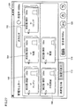
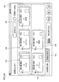
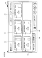
- Management system 2 includes a data storage device 300 and a display device 100.
- the data storage device 300 stores measurement information related to power consumption transmitted from the measuring device 400 associated with each electric device 200.
- the display device 100 provides a user interface that presents to the user the state of power consumption / generation in the power system 1 and accepts instructions regarding power management in the power system 1 from the user. Further, the display device 100 displays a graph related to power consumption based on measurement information related to power consumption stored in the data storage device 300.
- the display device 100 may be a portable type, may be detachable from a base disposed on a table, or may be fixed to a wall of a room.
- FIG. 1 shows a configuration example in which a plurality of display devices 100 are provided, even if there is only one display device 100, functions and processes according to this embodiment can be provided.
- FIG. 1 illustrates a management system 2 in which the display device 100 and the data storage device 300 are separate.
- a management device in which these functions are integrated as a single device (for example, a home controller). You may implement as. Such an implementation example will be described later.
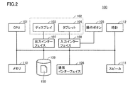
- FIG. 2 is a schematic diagram showing a hardware configuration of display device 100 included in management system 2 according to the embodiment of the present invention.
- display device 100 includes a CPU (Central Processing Unit) 101, touch panel 102 including display 103 and tablet 104, operation buttons 105, communication interface 106, output interface 107, and input interface 108.
- CPU Central Processing Unit
- the CPU 101 is a processing entity that controls the overall processing in the display device 100, and provides various functions as described later by executing a program stored in advance in the memory 110 or the like. In response to a user operation input from the tablet 104 or the operation button 105, the CPU 101 executes a process instructed by the user operation. Such instructions include instructions for operation / stop for the electric device 200, instructions for changing the control mode for the power conditioner 200Z, instructions for displaying the current or past power management state, and the like.
- the touch panel 102 is a device that provides a user interface, presents various information to the user according to instructions from the CPU 101, and outputs instructions input from the user to the CPU 101.
- the display 103 includes, for example, an LCD (Liquid Crystal Display), an organic EL (Electro Luminescence) display, and the like, and displays an image on the display surface.
- the tablet 104 detects a touch operation with a user's finger or the like, and outputs a coordinate value indicating a position where the touch operation is performed to the CPU 101.
- a tablet 104 is provided in association with the display surface of the display 103.
- the display device 100 does not necessarily include a touch panel, and may be any information that can be presented to the user.
- the operation buttons 105 are input means for accepting user operations, and typically one or a plurality of buttons are arranged on the surface of the display device 100.
- the operation button 105 includes a plurality of buttons and keys such as a determination button, a return button, a direction button, and a numeric keypad.
- the operation button 105 receives a user operation, the operation button 105 outputs information indicating the user operation to the CPU 101.
- the communication interface 106 performs data communication with the data storage device 300, the measuring device 400, the solar power generation device 200X, the storage battery 200Y, the power conditioner 200Z, and the like according to a command from the CPU 101. More specifically, the communication interface 106 includes the Ethernet (registered trademark), PLC (Power Line Communications), wireless LAN (Local Area Network) compliant with the IEEE 802.11 standard, ZigBee (registered trademark), as described above. Bluetooth (registered trademark), an infrared communication system, or the like is used.
- the output interface 107 mediates exchange of internal commands between the CPU 101 and the display 103.
- the input interface 108 mediates exchange of internal commands between the tablet 104 and / or the operation buttons 105 and the CPU 101.
- the hard disk 109 stores various data necessary for information processing in the display device 100. Details of the various data will be described later.
- the memory 110 is realized by a RAM (Random Access Memory) that is a volatile storage device, a ROM (Read-Only Memory) that is a nonvolatile storage device, and the like. Store the necessary work data.
- RAM Random Access Memory
- ROM Read-Only Memory
- the speaker 111 is an audio device, and outputs audio according to a command from the CPU 101.
- the clock 112 is a time measuring means and responds to the CPU 101 with the current date and time according to a command from the CPU 101.
- the hard disk 109 and / or the memory 110 may be realized using a storage medium connected via a communication interface.
- storage media include flash memory, mask ROM, EPROM (Electronically Programmable Read-Only Memory), EEPROM (Electronically Erasable Programmable Read-Only Memory), IC (Integrated Circuit) card and other semiconductor storage media, CD-ROM (Compact Disc-Read Only Memory) and optical disk storage media such as DVD-ROM (Digital Versatile Disk-Read Only Memory), magneto-optical disk storage media such as MO (Magnetic Optical Disc) and MD (Mini Disc), FD ( Magnetic storage media such as Flexible Disk), magnetic tape, and cassette tape can be used.
- flash memory includes flash memory, mask ROM, EPROM (Electronically Programmable Read-Only Memory), EEPROM (Electronically Erasable Programmable Read-Only Memory), IC (Integrated Circuit) card and other semiconductor storage media, CD-ROM (Compact Disc-Read Only Memory) and optical disk storage media such
- Information processing in the display device 100 is realized by the CPU 101 executing a program in cooperation with peripheral hardware components.
- a program is installed in advance in the memory 110 or the like.
- Such a program can be provided by being stored and distributed in an arbitrary storage medium.
- a program can be provided by downloading from a server device (or other device) connected to the Internet or the like. That is, the program stored in the storage medium is read out, or the program is acquired by downloading from the server device and temporarily stored in the memory 110 or the like.
- the CPU 101 expands the program stored in the memory 110 into an executable format and then executes the program.
- Storage media for storing such programs include semiconductor storage media such as flash memory, mask ROM, EPROM, EEPROM, and IC card, optical disk storage media such as CD-ROM and DVD-ROM, and optical disks such as MO and MD.
- Magnetic storage media such as magnetic disk storage media, FD, magnetic tape, cassette tape, etc. can be used.
- the CPU 101 may read and execute a program stored in another system or apparatus.
- a program read from a storage medium or the like is written to a memory or the like mounted on a function expansion board or function expansion unit mounted on the computer, it is stored in the function expansion board or function expansion unit according to the program.
- the function according to the present embodiment may be realized by performing all or a part of the necessary processing by a mounted arithmetic unit (CPU or the like).
- the program includes not only a program that can be directly executed by the CPU 101 but also a program in a source program format, a compressed program, and an encrypted program.
- FIG. 3 is a schematic diagram showing a hardware configuration of data storage device 300 included in management system 2 according to the embodiment of the present invention.
- data storage device 300 includes a CPU 301, a hard disk 302, a memory 303, a communication interface 304, and a clock 305.
- the CPU 301 is a processing entity that controls the overall processing in the data storage device 300, and provides various functions as described later by executing a program stored in advance in the memory 303 or the like.
- the hard disk 302 stores measurement information regarding power consumption transmitted from the measuring instruments 400A to 400E. Details of the measurement information storing process will be described later.
- the memory 303 is realized by a RAM which is a volatile storage device, a ROM which is a nonvolatile storage device, or the like, and stores a program executed by the CPU 301 and work data necessary for execution of the program by the CPU 301.
- the communication interface 304 performs data communication with the display device 100, the data storage device 300, the measuring device 400, the solar power generation device 200X, the storage battery 200Y, the power conditioner 200Z, and the like according to instructions from the CPU 301. Details thereof are the same as those of communication interface 106 (FIG. 2) described above, and thus detailed description thereof will not be repeated.
- the clock 305 is a time measuring means, and responds to the CPU 301 with the current date and time according to a command from the CPU 301.
- the hard disk 302 and / or the memory 303 may be realized using a storage medium connected via a communication interface.
- detailed description of the storage medium will not be repeated.
- Information processing in the data storage device 300 is realized by the CPU 301 executing a program in cooperation with peripheral hardware components.
- a program is installed in advance in the memory 303 or the like. Since such a program distribution and processing at the time of execution are the same as those of the program directed to the display device 100 described above, detailed description thereof will not be repeated.
- FIG. 4 is an external view of measuring instrument 400 included in management system 2 according to the embodiment of the present invention.
- FIG. 4A shows a perspective view including the socket 4001 of the measuring instrument 400
- FIG. 4B shows a side view of the measuring instrument 400
- FIG. A perspective view including a plug 4002 of the container 400 is shown.
- FIG. 5 is a schematic diagram showing a hardware configuration of measuring instrument 400 included in management system 2 according to the embodiment of the present invention.
- measuring instrument 400 is arranged to be inserted between a socket for supplying power flowing through power line 402 and a plug of electric device 200.
- a plug insertion socket 4001 is provided on the surface 4051 of the measuring instrument 400.
- a plug 4002 is provided on a surface 4053 which is a surface opposite to the surface 4051 of the measuring device 400.
- the socket 4001 is plugged into the electric device 200 and the plug 4002 is plugged into a socket (outlet / outlet) for supplying power via a power line 402 provided in the house.
- the thickness of the side surface 4052 is designed to be as small as possible.
- an LED 4041 and a setting button 4042 are provided on the surface 4051 of the measuring device 400.
- the LED 4041 displays a data processing state in the measuring device 400. More specifically, the LED 4041 varies the presence / absence of lighting, the presence / absence / cycle of blinking, the emission color, and the like according to the data processing state.
- the setting button 4042 is an input means for accepting a user operation. When the setting button 4042 is operated by the user, an initial setting in the measuring instrument 400 is started.
- measuring instrument 400 includes, in addition to socket 4001, plug 4002, LED 4041, and setting button 4042, a pair of main wirings 4004 and 4005 that electrically connect socket 4001 and plug 4002, A shunt resistor 4003 inserted in the wiring 4005, a power supply unit 4007, a power detection unit 4010, a communication module 4020, and an antenna 4030 are included.
- the power detection unit 4010 detects power flowing from the plug 4002 to the socket 4001. More specifically, the power detection unit 4010 includes a voltage input ADC (Analog to Digital Converter) 4011, a current input ADC 4012, a multiplier 4013, and a digital / frequency conversion unit 4014.
- ADC Analog to Digital Converter
- the voltage input ADC 4011 is connected to the main wirings 4004 and 4005 via the wirings V1P and V1N, respectively.
- the voltage input ADC 4011 outputs a digital signal indicating a voltage (potential difference) generated between the main wirings to the multiplier 4013.
- the current input ADC 4012 is electrically connected to both ends of the shunt resistor 4003 inserted in the main wiring 4005 via the wirings V2P and V2N.
- the shunt resistor 4003 is a minute (several hundred micro ⁇ ) resistor used for measuring a flowing current value.
- the current input ADC 4012 outputs a digital signal indicating the current value of the current flowing through the shunt resistor 4003 to the multiplier 4013.
- the multiplier 4013 multiplies the digital signal (voltage value) from the voltage input ADC 4011 by the digital signal (current value) from the current input ADC 4012, and a value obtained as a result (power consumption / unit: W or kW). Is output to the digital / frequency converter 4014.
- the digital / frequency conversion unit 4014 converts the digital signal from the multiplier 4013 into a frequency signal and outputs the resulting frequency signal to the communication module 4020.
- the power supply unit 4007 supplies power to each component of the measuring device 400.
- the power supply unit 4007 is connected to the main wirings 4004 and 4005, and uses part of the power flowing from the plug 4002 to the socket 4001 as power for operation of the measuring device 400.
- the power supply unit 4007 converts the AC power into DC power, and then supplies the DC power to the power detection unit 4010 and the communication module 4020.
- the communication module 4020 transmits a radio signal indicating the power consumption in the electric device connected to the socket 4001 calculated by the power detection unit 4010 via the antenna 4030. More specifically, the communication module 4020 includes a CPU 4021, a ROM 4022, a RAM 4023, a GPIO (General Purpose Input / Output) 4024, and a wireless RF (Radio Frequency) unit 4025.
- the GPIO 4024 receives the frequency signal input from the digital / frequency conversion unit 4014, and outputs information on the frequency signal to the CPU 4021.
- the CPU 4021 converts the frequency signal information from the GPIO 4024 according to a predetermined logic, and outputs the result to the wireless RF unit 4025.
- the wireless RF unit 4025 generates a wireless signal by modulating a carrier wave based on a data conversion result from the CPU 4021.
- a wireless signal generated by the wireless RF unit 4025 is transmitted via the antenna 4030.
- the CPU 4021 implements the processing as described above by executing a program stored in advance in the ROM 4022.
- the RAM 4023 stores work data necessary for the CPU 4021 to execute the program.
- FIG. 6 and FIG. 7 are diagrams for explaining the problems to be addressed by the embodiment of the present invention.
- the electric device 200 connected to the same measuring device 400 may be changed by replacement / addition of the electric device 200 or a redesign of the room.
- FIG. 6 for example, a case where the connection destination of the television 200B is changed to the measuring device 400C by changing the installation position of the television 200B connected to the measuring device 400B can be considered.
- measuring instrument 400 is disposed between a socket (outlet / outlet) for supplying electric power provided in a house or the like and a plug of electric device 200, so that electric power in electric device 200 is supplied. Since information on consumption can be easily measured, the arrangement position of the measuring device 400 can be determined relatively freely. Therefore, when looking at a certain measuring instrument 400, the electrical device 200 to be measured may be frequently changed.
- the measurement information transmitted from the measuring device 400 basically does not include information for specifying the electrical device 200 to be measured. That is, in general, the measuring instrument 400 does not have information for identifying the connected electric device 200.
- the history of the electric device 200 connected to the measuring device A is not properly managed, for example, at the “current” stage, information on power consumption (for example, a graph showing temporal transition of power consumption) Etc.), incorrect information will be displayed. That is, the information measured about the refrigerator is mixed in the television graph. Or the information measured about the television may mix in the graph about a refrigerator.
- information on power consumption for example, a graph showing temporal transition of power consumption
- the management system 2 solves the problem of mixing measurement information as described above by appropriately managing the association between the measuring device 400 and the electric device 200.
- the following two approaches are considered to solve such problems.
- FIG. 8 is a diagram for explaining the outline of the solving means in the embodiment of the present invention.
- FIG. 8A shows the first approach
- FIG. 8B shows the second approach.
- the measurement information is stored in time series separately from the measuring device 400 (measurement information table 350), and the history regarding the association between the measuring device 400 and the electric device 200 is stored. Information is held (history information table 150). And when the output of the electric power information regarding any of the electric devices 200 is requested, the selected information is extracted by referring to the contents of the history information table 150 and extracting the necessary measurement information from the measurement information table 350. In addition, power information related to the electrical device 200 is generated and output.
- the measurement information transmitted from each measuring device 400 is stored in time series in association with the electric device 200 (measurement information table 370).
- a correspondence relationship (correspondence relationship table 360) between the measuring device 400 and the electric device 200 (measurement target device) is set in advance, and the correspondence relationship table 360 is referred to.
- the measurement information transmitted from each measuring instrument 400 is sequentially stored in the measurement information table 370.
- power information related to the selected electrical device 200 is generated and output based on the measurement information table 370.
- the management system 2 manages power related to power consumption in at least one electric device 200.
- the management system 2 has a function (measurement information table 350) for storing measurement information related to power consumption in the electric device 200 transmitted from the measuring device 400 associated with each electric device 200 in time series separately for the measuring device 400. ) And a function (history information table 150) for storing history information related to the association between the measuring instrument and the electric device.
- the data storage device 300 manages the measurement information table 350
- the display device 100 manages the history information table 150.
- the management system 2 responds to the selection of the electric device 200 by a user or the like, and among the measurement information (measurement information table 350) stored separately for the measuring device 400, the measurement corresponding to the selected electric device 200 is performed. By extracting information, it has a function of outputting power information about the selected electrical device 200.
- the function of outputting power information may exist in either one or both of the display device 100 and the data storage device 300.
- a configuration in which the display device 100 has a function of outputting power information will be described as a typical configuration.
- FIG. 9 shows an example of the data structure of a table used in management system 2 according to the first embodiment of the present invention.
- FIG. 9A shows an example of the measurement information table 350
- FIG. 9B shows an example of the history information table 150.
- the data storage device 300 stores measurement information related to power consumption in each electric device 200 in time series separately from the measuring device 400. That is, measurement information is sequentially stored in the measurement information table 350 shown in FIG. 9A separately from the measuring device 400 at predetermined time intervals. More specifically, the measurement information table 350 includes a column 3501 that stores identification information of the measuring device 400 and a column 3502 that sequentially stores measurement information transmitted from the corresponding measuring device 400.
- the column 3501 stores information for identifying each of the measuring instruments 400 under the management system 2.
- FIG. 9A shows an example in which the name of the measuring device 400 is stored in the column 3501, but a network address (MAC address or IP address) may be used.
- measurement information transmitted from each measuring device 400 is sequentially stored in a row corresponding to the measuring device 400 that is the transmission source of the measurement information. That is, measurement information A (t1) measured at measuring device A at time t1 is stored in a row corresponding to measuring device A, and measurement information A (t2) measured at measuring device A at time t2 is stored. Stored in subsequent columns of the same row. The measurement information measured by other measuring devices 400 is also stored in the same manner.
- the history information table 150 shown in FIG. 9B stores history information indicating when each electrical device 200 (measurement target device) is connected to which measuring device 400. That is, the history information table 150 stores the time when the association with the measuring device 400 is validated and the information for identifying the associated measuring device 400 separately for each electric device 200.
- the history information table 150 corresponds to a column 1501 that stores identification information of the electric device 200 (measurement target device), and a column 1502 that indicates the date and time when the connection of the corresponding electric device 200 was started. It includes a column 1503 indicating the date and time when the connection of the electric device 200 is completed, and a column 1504 that stores identification information of the measuring instrument 400 to which the corresponding electric device 200 is connected. As shown in the column of “Measurement target device 1” in FIG. 9B, each time the connection destination of the same electrical device 200 (measurement target device) is changed, the contents related to the change (connection destination The identification information, connection start date and time, and connection end date and time of the measuring device 400 are updated.
- the management system 2 stores history information related to the association between the measuring device 400 and the electric device 200.
- the management system 2 only needs to be able to hold the data stored in the measurement information table 350 and the history information table 150 described above, and thus is not limited to the data structure shown in FIG. can do.
- a single device may store both the measurement information table 350 and the history information table 150.
- E3 Measurement information
- power information about electric device 200 selected by the user is output using measurement information table 350 and history information table 150, but before that, measurement is performed by measuring instrument 400. Measurement information and its transmission method will be described.
- the measuring device 400 basically measures the power consumption (instantaneous power consumption (unit: W or kW)) consumed by the connected electrical equipment. By integrating the instantaneous power consumption over a predetermined time, the power consumption amount (unit: Wh or kWh) of the electric device is calculated.
- the display device 100 can display both the instantaneous power consumption and the power consumption of each electric device. Furthermore, it is also possible to group a plurality of electric devices and display the instantaneous power consumption and power consumption for the entire group.
- an implementation example of measurement information about the corresponding electrical device 200 transmitted from the measuring device 400 is as follows (however, it is not limited to the following example).
- the measuring device 400 periodically transmits the power consumption for each transmission cycle as measurement information by accumulating the instantaneous power consumption in the electric device 200 over the transmission cycle. That is, the amount of electric power (unit: Wh or kWh) consumed by the electric device 200 between the previous transmission and the current transmission is transmitted every predetermined period.
- the measuring device 400 measures the instantaneous power consumption (unit: W or kW) in the electric device 200 at a predetermined cycle (for example, every second), and the measured moment at the same transmission cycle as the measurement cycle. Power consumption is transmitted as measurement information.
- the measuring device 400 measures the instantaneous power consumption in the electric device 200 every predetermined cycle (for example, every second), and the transmission cycle is longer than the measurement cycle, and between the previous transmission and the current transmission. A plurality of measured instantaneous power consumptions are transmitted as measurement information.
- the measuring device 400 measures the instantaneous power consumption in the electric device 200 at a predetermined cycle (for example, every second), and the transmission cycle is longer than the measurement cycle and between the previous transmission and the current transmission.
- An average instantaneous power consumption obtained by averaging a plurality of measured instantaneous power consumptions is transmitted as measurement information.
- the measurement includes the power consumption that is obtained by integrating the instantaneous power consumption or average instantaneous power consumption and the multiple instantaneous power consumption measured from the previous transmission to the current transmission. Send information. Further, an average value, minimum value, maximum value, etc. of a plurality of instantaneous power consumption may be added.
- the time information acquired by the measuring device 400 by some means may be added to the measurement information, generally, when the data storage device 300 receives the measurement information, the time at that time is acquired from the clock 305. And stored in the measurement information table 350 in association with the received measurement information.
- any protocol can be adopted for the exchange of measurement information between the data storage device 300 and the measuring instrument 400.
- a configuration is adopted in which the measuring device 400 broadcasts a packet including its own measurement result and the data storage device 300 receives this packet.
- the data storage device 300 may periodically poll each measuring device 400.
- FIG. 10 is a diagram for describing output processing of power information in management system 2 according to the first embodiment of the present invention.
- FIG. 10A schematically shows types of measurement information stored in the measurement information table 350.
- the measurement target device 1 is connected to the measuring device A until 23:45 of 20111/2/1, and thereafter the measurement target device 2 is connected until 17:50 of 2011/7/2. Thereafter, it is assumed that the measurement target device 1 is connected again until now. Further, it is assumed that the measurement target device 1 is connected to the measuring device B from 23:45 of 20111/2/1 to 10:05 of 2011/4/15. Further, it is assumed that the measurement target device 3 is connected to the measuring device C from 10:05 of 2011/4/15 to the present.
- the history information table 150 holds history information indicating a history relating to the association between the measuring device 400 and the electric device 200 as shown in FIG.
- the display device 100 refers to the history information stored in the history information table 150, extracts measurement information for a necessary period from the measurement information table 350, and outputs power information.
- FIG. 10B shows a procedure for generating power information for each of the measurement target devices 1 to 3.
- the measurement information from 23:45 of 20111/2/1 to 10:05 of 2011/4/15 stored in association with the measuring device B
- the power information is generated using the measurement information from 2011/7/2 17:50 to the present stored in association with the measuring device A.
- FIG. 11 is a diagram showing a display example of power information provided in the management system 2 according to the first embodiment of the present invention.
- a power information display screen 600 shown in FIG. 11 is displayed on the touch panel 102 of the display device 100.
- the display screen 600 includes a graph 602 showing a history of power consumption for the designated electrical device 200 over a period designated by the user.
- This graph 602 shows the power consumption for the electric device 200 selected by the user operating the selection icon 610.
- the power consumption for the period selected by the user operating the period icon 606 is shown.
- the display screen 600 includes buttons 614, 616, and 618 for selecting a display period. Buttons 614, 616, and 618 designate “day”, “month”, and “year”, respectively. “Day” indicates the temporal change in power consumption during the designated day, “Month” indicates the temporal change in power consumption during the designated January, and “Year” , Shows the temporal change in power consumption during the specified year.
- the display content of the period icon 606 is also updated according to the period selected by the buttons 614, 616, and 618.
- the power consumption for the plurality of electric devices 200 is displayed in a graph on the same time axis. At this time, different colors, patterns, etc. are attached so that each electric device 200 can be distinguished (compared).
- the display screen 600 also includes a status display 604 that indicates the power supply / demand status of the current power system 1. Further, when the user selects the button 612, the current power consumption and power consumption for the designated electrical device are displayed.
- the power information can be output (presented) to the user in various forms based on the measurement information measured by the measuring device 400, not limited to the display screen 600 as described above.
- the power information output mode may be information transmission by e-mail, information disclosure by the Web, print output to a paper medium by a printer, or the like.
- FIG. 12 is a sequence diagram showing a processing procedure in management system 2 according to the first embodiment of the present invention.
- each of one or a plurality of measuring instruments 400 measures information related to power consumption in the connected electric device 200 (step S10), and stores the measurement information acquired by the measurement as data. It transmits to the apparatus 300 (step S12).
- the data storage device 300 stores the measurement information received from each measuring device 400 in time series separately for each measuring device 400 (step S14). The processes in steps S10 to S14 are repeated for each predetermined period or for each predetermined condition.
- step S20 the user changes the electric device 200 connected to any of the measuring devices 400 (step S20).
- step S22 the user performs a setting change operation associated with this change on the display device 100 (step S22).
- the display device 100 updates the contents of the history information table 150 according to the setting change operation performed by the user (step S24). Even during and after the change of the contents of the history information table 150, the processes in steps S10 to S14 are repeated for each predetermined period or for each predetermined condition.
- step S30 This requesting operation includes selection of an electric device 200 (measurement target device) to which power information is output.
- the display device 100 refers to the history information table 150 to search for history information about the selected electrical device 200, and based on the history information obtained as a result of the search, Of the measurement information for each measuring instrument 400 stored in the data storage device 300, the required measurement information is requested (step S32).
- the data storage device 300 extracts necessary measurement information from the measurement information table 350 according to the requested measurement information, and transmits it to the display device 100 (step S34). Based on the measurement information received from the data storage device 300, the display device 100 outputs power information about the electrical device 200 selected by the user (step S36).
- the requested power information is created and output by the same process as described above.
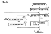
- the management system 2 provides a user interface screen for accepting designation of the associated electric device 200 for each measuring device 400.
- 13 to 17 are diagrams showing examples of user interface screens related to setting change operations provided in the management system 2 according to the first embodiment of the present invention.
- a user interface screen 650 as shown in FIG. 13 is presented on the touch panel 102.
- the user interface screen 650 displays a list of measuring instruments 400 that can communicate with the management system 2 (displayed as “power measuring device” in FIG. 13), and an identification number for each measuring instrument 400 ( In the example shown in FIG. 13, the MAC address), the associated electric device 200, and its installation location are displayed.
- the user interface screen 650 includes a replacement button 661, a setting button 662, a delete button 663, and a completion button 664.
- the replacement button 661 When the user selects the replacement button 661, the information on the associated electric device 200 is switched between the two selected measuring instruments 400 among the measuring instruments 400 displayed in the list (about the user interface for selection). Is not shown). Therefore, it is more convenient when the electric device 200 connected to each other is exchanged between the two measuring devices 400.
- FIGS. 14 to 17 When the user selects the setting button 662, a series of setting operations shown in FIGS. 14 to 17 can be performed. In the example with reference to FIGS. 14 to 17 to be described later, a setting operation when performing a setting operation on the third measuring device 400 not associated with any electric device 200 will be described.
- the delete button 663 When the user selects the delete button 663, the setting information of the electric device 200 associated with the pre-selected measuring instrument 400 is deleted.
- the completion button 664 the user exits the setting change mode and returns to the menu screen.
- the user interface screen 651 input of the floor where the electric device 200 connected to the selected measuring device 400 is installed is requested.
- the first floor (1F) to the fifth floor (5F) and the rooftop are listed as options.
- the screen transitions to a user interface screen 652 shown in FIG.
- the user interface screen 652 requires input of a room (area) where the electric device 200 connected to the selected measuring instrument 400 is installed.
- a room area
- the entrance, the living room, the kitchen, the dining room, the study, and the children's room are listed as options.
- the screen transitions to a user interface screen 653 shown in FIG.
- the user interface screen 653 On the user interface screen 653, input of the type of the electric device 200 connected to the selected measuring device 400 is requested.
- a list of TVs, air conditioners, lights, recorders, and microwave ovens is displayed as options.
- the user interface screen 654 presents that information about the electric device 200 input by a series of operations is associated with the third measuring device 400.
- the display device 100 stores the contents of the change in the history information table 150 together with the time when the change is made. To do.
- the measurement information transmitted from the measuring device 400 basically includes the power consumption (instantaneous power consumption (unit: W or kW)) consumed by the connected electrical device 200.
- the power consumption is sequentially stored in the measurement information table 350.
- the measurement information table 350 it is possible to display a graph 602 as shown in FIG. 11 using information stored therein as it is.
- the integrated amount of power consumption power consumption (unit: Wh or kWh)
- the average power consumption or the power consumption amount within a unit time may be calculated and stored in the measurement information table 350.
- the measuring device 400 may be reset for some reason, and the power consumption accumulated before that may be deleted. In such a case, it is necessary to further correct an error caused by erasing the power consumption. Hereinafter, such correction processing will be described.
- FIG. 18 is a diagram for describing measurement information correction processing in management system 2 according to the embodiment of the present invention.
- FIG. 18A shows an example of a temporal change in the value of the measurement information when the measuring device 400 transmits the accumulated power consumption as the measurement information.
- the power consumption in the electrical device 200 in a certain period corresponds to the difference between the cumulative power consumption in the period and the cumulative power consumption in the immediately preceding period. Therefore, the difference calculated in each period is sequentially stored in the measurement information table 350.
- the measuring device 400 has been reset for some reason at time t0.
- the information held by the measuring instrument 400 until immediately before is deleted by the reset, and the accumulated power consumption is also cleared to zero. That is, as shown in FIG. 18A, the accumulated power consumption increases from zero immediately after resetting.
- the amount of power consumption between time t1 and time t2 is the difference between the power consumption amount E (t2) at time t2 and the power consumption amount E (t1) at time t1.
- E (t1-2) E (t2) -E (t1)).
- the measuring instrument 400 may be notified from the measuring instrument 400, or the cumulative power consumption has changed beyond a predetermined threshold before and after the period. Alternatively, it may be determined that it has been reset.
- the management system 2 stores information for identifying the latest associated measuring device 400 as history information separately for each electric device 200. By using such history information, measurement information from at least one previous connection change of each electrical device 200 can be output as power information.
- FIG. 19 is a diagram showing an example of the data structure of the history information table 150A used in the management system 2 according to the first modification of the first embodiment of the present invention.
- the history information table 150A stores to which measuring device 400 each electric device 200 (measurement target device) is connected, and the date and time when the connection was started.
- the history information table 150A includes association between the electric device 200 and the measuring instrument 400 and valid time information indicating the time when the association is valid.
- the history information table 150A corresponds to a column 1501 that stores identification information of the electric device 200 (measurement target device), and a column 1502 that indicates the date and time when the connection of the corresponding electric device 200 was started. And a column 1504 for storing identification information of the measuring device 400 to which the electric device 200 is connected.
- the history information table 150A stores only the point where the column 1503 is removed and the identification information of the measuring instrument 400 connected most recently. Is different.
- the history information table 150A illustrated in FIG. 19 is described corresponding to the “current” state illustrated in FIG. 10. For the measurement target device 2 that is not connected to any measuring device 400, the history information table 150A is illustrated. Are also null (column 1502 and column 1504).
- the data storage device 300 stores the measurement information in time series separately from the measuring device 400 as described in the first embodiment (measurement information table 350).
- display device 100 refers to history information table 150 ⁇ / b> A, and measurement target device 1 is connected to measuring instrument A from 17:50 on 2011/7/2 to the present. Can be determined. Therefore, the display device 100 extracts the measurement information from 17:50 of 2011/7/2 stored in association with the measuring device A in the measurement information table 350 to the present, and the power information about the measurement target device 1 Is generated. Further, the display device 100 extracts measurement information from 10:05 on 2011/4/15 stored in association with the measuring device B in the measurement information table 350 to the present, and the power information about the measurement target device 3 Is generated. However, since the measurement target device 2 is not connected to the measuring instrument 400, power information is not generated. Also, the measurement target devices 1 and 3 are not generated for the power information when they are connected to another measuring device 400 before the currently connected measuring device 400.
- At least measurement information from the connection change of each electrical device 200 at least once can be output as power information, so that correct power information is generated while simplifying management of history information. And can output.
- the measurement information table 350 and the history information table 150A are stored as examples. However, these may be implemented as an integrated table.
- FIG. 20 is a diagram showing an example of the data structure of the measurement information table 350B used in the management system 2 according to the second modification of the first embodiment of the present invention.
- the measurement information table 350B shown in FIG. 20 is described corresponding to the “current” state shown in FIG.
- the measurement information table 350B includes a column 3509 for storing identification information of the electric device 200 (measurement target device) that is most recently associated / associated with the corresponding measuring device 400, and the connection of the corresponding electric device 200 is started. And a column 3508 indicating the date and time (date and time when the association was validated). Further, measurement information from the measuring instrument 400 is stored in time series in the measurement information table 350B (column 3502B).
- the measurement information for each measuring device 400 is stored in the measurement information table 350B, starting from the “connection start date and time” for the corresponding electric device 200 (measurement target device). More specifically, referring to FIG. 10, the measurement information corresponding to the “measurement device A” in the measurement information table 350B is the measurement information measured by the measurement device A as shown in FIG. This corresponds to a portion from 17:50 to the present on 2011/7/2 in which the connected electrical device is changed from “measurement target device 2” to “measurement target device 1”. Similarly, the measurement information corresponding to the “measurement device C” in the measurement information table 350B is connected to the “measurement target device 3” among the measurement information measured by the measurement device C as shown in FIG.
- the measurement information corresponding to the “measurement device B” in the measurement information table 350B is connected to the “measurement target device 1” among the measurement information measured by the measurement device B as shown in FIG. , Corresponding to a portion from 23:45 of 20111/2/1 to 17:50 of 2011/7/2.
- the display device 100 refers to the measurement information table 350B, extracts the measurement information stored in association with the measuring device B starting at 23:45 of 20111/2/1, and 2011/7/2.
- the measurement information stored in association with the measuring instrument A is extracted starting from 17:50, and power information about the measurement target device 1 is generated.
- the extracted measurement information does not overlap on the time axis in principle.
- the display device 100 refers to the measurement information table 350B, and extracts measurement information stored in association with the measuring device C starting at 10:05 on 2011/4/15, thereby measuring the measurement target device. 3 is generated.
- At least the latest measurement information about the electric device 200 connected to each measuring device 400 can be output as power information, so that correct power information is generated while simplifying management of history information. And can output.
- the management system 2 in which the display device 100 and the data storage device 300 are separate has been described as an example. However, the management in which these functions are integrated is described. It may be implemented as a device.
- a home controller 100A will be described as a typical example of a management apparatus equipped with a function related to the management system 2.
- FIG. 21 is a schematic diagram showing an overall configuration of an electric power system 1A including a home controller 100A according to a third modification of the first embodiment of the present invention.
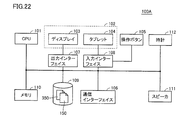
- FIG. 22 is a schematic diagram showing a hardware configuration of home controller 100A according to the third modification of the first embodiment of the present invention.
- the home controller 100A is provided with a home controller 100A in place of the display device 100 and the data storage device 300 as compared with the power system 1 shown in FIG.
- the hardware configuration of the home controller 100A illustrated in FIG. 22 is the same as that of the display device 100 illustrated in FIG. However, the home controller 100A is different in that the measurement information table 350 is stored and managed in addition to the history information table 150 (or the history information table 150A).
- Home controller 100A is provided by any one of management system 2 according to the first embodiment, management system 2 according to the first modification of the first embodiment, and management system 2 according to the second modification of the first embodiment. Provides functionality on a single device. Information processing in the home controller 100A is realized by the CPU 101 (FIG. 22) executing a program in cooperation with peripheral hardware components. Generally, such a program is installed in advance in the memory 110 or the like.
- Such a program can be provided by being stored and distributed in an arbitrary storage medium.
- such a program can be provided by downloading from a server device connected to the Internet or the like. That is, the program stored in the storage medium is read out, or the program is acquired by downloading from the server device and temporarily stored in the memory 110 or the like.
- the CPU 101 expands the program stored in the memory 110 into an executable format and then executes the program.
- Storage media for storing such programs include semiconductor storage media such as flash memory, mask ROM, EPROM, EEPROM, and IC card, optical disk storage media such as CD-ROM and DVD-ROM, and optical disks such as MO and MD.
- Magnetic storage media such as magnetic disk storage media, FD, magnetic tape, cassette tape, etc. can be used.
- the management system 2 also manages power related to power consumption in at least one electric device 200.
- the management system 2 has a function of acquiring measurement information related to power consumption in the electric device 200 transmitted from the measuring device 400 associated with each electric device 200, a preset measuring device 400, and the electric device 200. Based on the corresponding relationship (correspondence relationship table 360), the measurement information acquired from each measuring device 400 is associated with the corresponding electric device 200 and stored in time series (measurement information table 370).
- the data storage device 300 manages the correspondence table 360 and the measurement information table 370. Furthermore, the management system 2 has a function of outputting power information for each electrical device 200 based on measurement information (measurement information table 370) stored in time series in association with the electrical device 200.
- the function of outputting power information may exist in either one or both of the display device 100 and the data storage device 300.
- a configuration in which the display device 100 has a function of outputting power information will be described as a typical configuration.
- FIG. 23 is a diagram for describing measurement information storage processing in management system 2 according to the second embodiment of the present invention.
- FIG. 23 shows an example in which the correspondence relationship between the electric device 200 and the measuring instrument 400 is changed as in FIG. 10 described in the first embodiment.
- the measurement target device 1 is associated with the measuring device A, and the data storage device 300 uses the measurement information acquired from the measuring device A as the measurement target. It is associated with the device 1 and stored in time series.
- the correspondence relationship between the electric device 200 and the measuring instrument 400 is updated after this period T1. That is, in the period T2 (from 23/45 of 20111/2/1 to 10:05 of 2011/4/15) following the period T1, the measuring object device 2 is associated with the measuring device A, and the measuring device The measurement target device 1 is associated with B. Therefore, the data storage device 300 stores the measurement information acquired from the measuring device A in time series in association with the measurement target device 2, and stores the measurement information acquired from the measurement device B in time series in association with the measurement target device 1. To do.
- the measurement information acquired from each measuring device 400 is stored in time series in association with the electric device 200 (measurement target device).
- the measurement information is stored in time series separately for each electrical device 200 (measurement target device)
- the power information for each electrical device 200 (measurement target device) can be easily output.
- FIG. 24 shows an exemplary data structure of a table used in management system 2 according to the second embodiment of the present invention.
- FIG. 24A shows an example of the correspondence table 360
- FIG. 24B shows an example of the measurement information table 370.
- the correspondence relationship table 360 shown in FIG. 24A and the measurement information table 370 shown in FIG. 24B are described corresponding to the “current” state shown in FIG.
- the data storage device 300 refers to the correspondence relationship table 360 to determine the correspondence relationship between each measuring device 400 and the electric device 200. More specifically, the correspondence table 360 stores a column 3601 that stores identification information of the electric device 200 (measurement target device), and a column that stores identification information of the measuring device 400 to which the corresponding electric device 200 is connected. 3602. For each electrical device 200 (measurement target device), each time the connection destination measuring device 400 is changed, the contents of the corresponding column 1502 are updated at the time when the connection is changed, and the corresponding column 1504 is also updated. Is updated to the identification information of the connected measuring instrument 400. 24A shows an example in which the name of the measuring device 400 is stored in the column 3602, but a network address (MAC address or IP address) or the like may be used.
- MAC address MAC address or IP address
- the measurement information table 370 includes a column 3701 for storing identification information of the electric device 200 (measurement target device) and a column 3702 for sequentially storing measurement information about the corresponding electric device 200 (measurement target device).
- measurement information transmitted from each measuring device 400 is sequentially stored in a row corresponding to the connected electric device 200.
- the measurement information A (t1) measured at the time t1 measured by the measuring device A is stored in a row corresponding to the measuring target device 2 if the measuring device A is connected to the measuring target device 2 at the time t1.
- the measurement information B (t1) measured at the time t1 measured by the measuring device B is stored in a row corresponding to the measuring target device 1 if the measuring device B is connected to the measuring target device 1 at the time t1. The Thereafter, the same processing is repeated until the connection change (update of the correspondence table 360) is made.
- the measurement instrument A measures the line corresponding to the measurement target device 1 thereafter. Measurement information A (tN + 1) is stored.
- the measurement information table 370 may store measurement information together with information for identifying the measuring instrument 400 as a measurement source. That is, in the example shown in FIG. 24B, information indicating that the measurement information A (t1) is from “measurement device A” may be added.
- the management system 2 associates the measurement information acquired from each measuring device 400 with the corresponding electric device 200 based on the preset correspondence relationship between the measuring device 400 and the electric device 200. To store in time series.
- the management system 2 only needs to be able to hold the data stored in the correspondence relationship table 360 and the measurement information table 370 described above, and thus is not limited to the data structure shown in FIG. 24 and employs an arbitrary data structure. can do.
- the correspondence relationship table 360 and the measurement information table 370 may be managed by different devices.
- measurement information is stored in time series in the measurement information table 370 in association with the electric device 200. Therefore, measurement information about the electric device 200 selected by the user can be easily extracted.
- the management system 2 typically presents the display screen 600 shown in FIG. That is, the measurement information stored in each row of the measurement information table 370 can be used as it is for generating the graph 602 in the display screen 600 shown in FIG. Therefore, the output process of power information can be simplified.
- the management system 2 is not limited to the display screen 600 as shown in FIG. 11, and outputs power information to the user in various forms based on the measurement information stored in the measurement information table 370 ( Present).
- the power information output mode may be information transmission by e-mail, information disclosure by the Web, print output to a paper medium by a printer, or the like.
- FIG. 25 is a sequence diagram showing a processing procedure in management system 2 according to the second embodiment of the present invention.
- each of one or a plurality of measuring devices 400 measures information related to power consumption in the connected electric device 200 (step S50), and stores the measurement information acquired by the measurement as data. It transmits to the apparatus 300 (step S52).
- the data storage device 300 receives the measurement information from any of the measuring devices 400, the data storage device 300 refers to the correspondence table 360 to identify the electrical device 200 associated with the measuring device 400 that is the transmission source of the measurement information ( Step S54). Then, the data storage device 300 stores the measurement information received from the measuring instrument 400 in time series in the measurement information table 370 in association with the corresponding electrical device (step S56).
- the processes in steps S50 to S56 are repeated for each predetermined period or for each predetermined condition.
- step S60 the user changes the electric device 200 connected to any of the measuring devices 400 (step S60).
- step S62 the user performs a setting change operation associated with this change on the display device 100
- step S62 the display device 100 transmits setting change information indicating the content of the setting change operation performed by the user to the data storage device 300.
- the data storage device 300 updates the contents of the correspondence table 360 based on the setting change information (step S74). Even after the contents of the correspondence table 360 are changed, the processes in steps S50 to S56 are repeated for each predetermined period or for each predetermined condition.
- step S70 This requesting operation includes selection of an electric device 200 (measurement target device) to which power information is output.
- the display device 100 requests measurement information about the selected electrical device 200 from the data storage device 300 (step S72).
- the data storage device 300 extracts measurement information associated with the designated electric device 200 from the measurement information table 370 and transmits the measurement information to the display device 100 (step S74).
- the display device 100 Based on the measurement information received from the data storage device 300, the display device 100 outputs power information about the electric device 200 selected by the user (step S76).
- the requested power information is created and output by the same process as described above.
- the correspondence table 360 indicating the correspondence between the measurement device 400 and the electric device 200 set in advance and the measurement information acquired from each measurement device 400 are associated with the corresponding electric device 200.
- the example which comprises separately the measurement information table 370 stored in time series was shown, since the identification information of the electric equipment 200 (measurement target equipment) is a key in any table, both are the same.
- FIG. 26 is a diagram showing an example of the data structure of the measurement information table 370A used in the management system 2 according to the first modification of the second embodiment of the present invention.
- measurement information table 370A indicates a column 3701 for storing identification information of electric device 200 (measurement target device) and the date and time when connection of corresponding electric device 200 (measurement target device) is started.
- a column 3702, a column 3705 for storing identification information of the measuring instrument 400 to which the corresponding electric device 200 (measurement target device) is connected, and measurement information about the corresponding electric device 200 (measurement target device) are sequentially stored.
- the contents of the corresponding columns 3074 and 3075 are updated each time the measuring device 400 to which the connection is made is changed. That is, the content of the column 3074 is updated at the time when the connection is changed, and the content of the column 3075 is updated to identification information indicating the measuring device 400 after the connection is changed.
- the data storage device 300 When the data storage device 300 receives the measurement information from any of the measuring devices 400, the data storage device 300 refers to the measurement information table 370A, and the electric device 200 (measurement information) associated with the measuring device 400 that is the transmission source of the measurement information. A row) in the table 370A is specified, and the received measurement information is sequentially stored in the specified row.
- the number of table accesses by the data storage device 300 can be reduced, and management of correspondence and measurement information can be facilitated.
- connection start date stored in the column 3074 of the measurement information table 370A is not essential.
- this “connection start date and time” can also be displayed in an overlapping manner on the power information display screen 600 shown in FIG. 11, so that the user has a corresponding relationship between the current measuring instrument 400 and the electric device 200. You can know when it is effective.
- the management system 2 in which the display device 100 and the data storage device 300 are separate has been described as an example.
- the management system 2 is implemented as an integrated management device. May be.
- a typical example of a management apparatus equipped with such a function related to the management system 2 is implemented as a home controller. Since the overall configuration of the power system including such a home controller is the same as that of power system 1A shown in FIG. 21 described above, detailed description will not be repeated. Since the hardware configuration of the home controller is the same as the hardware configuration of home controller 100A shown in FIG. 22 described above, detailed description will not be repeated.
- the home controller provides the entire function provided by the management system 2 according to the above-described second embodiment or the management system 2 according to the first modification of the second embodiment with a single device.
- Information processing in the home controller is realized by the CPU 101 (FIG. 22) executing a program in cooperation with peripheral hardware components.
- a program is installed in advance in the memory 110 or the like. Since such a program provision form has also been described in the first embodiment, detailed description thereof will not be repeated.
- the home controller presents information related to the state of power consumption that is useful for the user regarding a plurality of electrical devices.
- presentation of the information in the home controller will be described.
- FIG. 27 is a diagram illustrating a home appliance monitor screen displayed on display 103 of display device 100 according to the third embodiment of the present invention.
- FIG. 4 shows a screen on which information related to the power consumption of the electric devices belonging to the group is displayed as an object. The information related to the power consumption of the electrical device is based on the measurement information measured by the corresponding measuring device 400.
- a plurality of power management objects are displayed, and as an example, a case where five power management objects 502 to 510 provided so as to be selectable are shown.
- a setting button 520 for providing the above-described user interface screen for setting change is provided. As described above, the setting button 520 is selected, and the correspondence relationship (correspondence relationship table) between the measuring instrument 400 and the electric device 200 (measurement target device) described above according to the series of operations of FIGS. 360) can be set. At this point, when the association between any measuring instrument 400 and the electric device 200 is registered by the operation, the registration contents (attribute information, etc.) are stored in the correspondence table 360 of the hard disk 109 of the display device 100.
- a plurality of attribute information of the electric device 200 is associated and registered.
- the first floor is registered as the first attribute information (installed floor)
- the child room is used as the second attribute information (installed room (area)).
- grouping with respect to the some electric equipment according to this Embodiment 3 is performed based on the said attribute information.
- each power management object for example, information on the power consumption of the electric devices belonging to each classified group is shown, and the total power consumption value of the electric device group is shown.
- the display is not limited to the value of power consumption, and may be, for example, the value of the total power consumption (Wh or kWh) of the electrical equipment group or may be displayed together. Any information regarding consumption may be used.
- the present invention is not limited to this method, and a priority order is assigned to attribute information to be described later. They may be arranged in the order of priority.
- the home appliance monitor screen 500 shows a case where grouping is performed according to the floor of the house (first grouping).
- each group grouped according to the floor a case where each group is further grouped (second grouping) is shown.
- the power management objects 502 to 506 provided in the upper area correspond to the 1F group, and the case where the room is further classified into three groups is shown.
- the power management object 502 attribute information “floor” and “room” are displayed.
- the floor of the house is 1F, and the room corresponds to the kitchen.
- the number of corresponding measuring devices is shown as indicating the number of electric devices belonging to the group, and in this example, the case of three is shown as an example.
- the power consumption 580w of the three measuring devices is displayed as information related to power consumption.
- a bar graph is displayed together with a numerical value, so that the value of power consumption can be intuitively grasped and can be easily compared with other power management objects.
- a display form of the power management object 502 a plurality of cards (four cards) are overlaid, and a card object in a state where it seems to be combined with a clip-shaped object is displayed.
- the foremost card is a device general card
- the card that is arranged on the back and displayed in an overlapping form is a device card that corresponds to the measuring instrument.
- the number of instrument cards corresponds to the number of measuring instruments, that is, three electrical instruments, and three cards are arranged behind the frontmost card according to the number of three measuring instruments. It is displayed. And it is displayed in the form where the position was shifted a little so that each card could be seen.
- a limit may be set for the number of device cards, for example, a maximum of three.
- a device general card that summarizes the device cards that are visible on the device card, and displays information related to power consumption in the card so that the device cards can be collected with clip-shaped objects. It is possible to intuitively understand that the information is related to the power consumption grouped and grouped by making it visible. The same applies to the display forms of other power management objects.
- attribute information “floor” and “room” are displayed.
- the floor of the house is 1F, and the room corresponds to the bedroom.
- the number of electrical devices belonging to the group corresponds to the number of measuring instruments.
- the power consumption 680w of the two measuring devices is displayed as information related to power consumption.
- attribute information “floor” and “room” are displayed.
- the floor of the house is 1F, and the room corresponds to the kitchen.
- the number of electrical devices belonging to the group corresponds to the number of measuring instruments. Then, based on the measurement information of the measuring device, the power consumption 780w of the two measuring devices is displayed as information related to power consumption.
- the power management objects 508 and 510 provided in the lower area correspond to the 2F group, and the case where the room is further classified into two groups is shown.
- attribute information “floor” and “room” are displayed.
- the floor of the house is 2F and the room corresponds to the child room.
- the number of electrical devices belonging to the group corresponds to the number of measuring instruments. Then, based on the measurement information of the measuring device, the power consumption 330w of one measuring device is displayed as information regarding power consumption.
- attribute information “floor” and “room” are displayed.
- the floor of the house is 2F and the room corresponds to the bedroom.
- the number of electrical devices belonging to the group corresponds to the number of measuring instruments. Then, based on the measurement information of the measuring device, the power consumption 130w of one measuring device is displayed as information regarding power consumption.
- the power management objects in the home appliance monitor screen 500 correspond to buttons that can be selected, respectively, and by selecting the power management object, a detailed group detail screen in the group of the power management objects is displayed. (FIG. 28) is displayed.
- a grouping of a plurality of hierarchies is performed and displayed based on a plurality of attribute information, respectively, so that even when the number of electrical devices is large, classification is performed for each group. It is possible to easily grasp the power consumption state of the electrical equipment group. In addition, by setting the electrical equipment and attribute information in association with each other, it is possible to classify according to the attribute information without depending on the installation status. By grouping using attribute information that is easy to grasp as a group such as “room”, it is possible to present information regarding the state of power consumption useful for the user.
- a boundary line is provided for distinguishing between the upper region and the lower region so that the classified state can be grasped more clearly.
- a boundary line is provided for distinguishing between the upper region and the lower region so that the classified state can be grasped more clearly.
- the priority order of the attribute information “floor” a priority order in which the lower floors are given priority in the order of 1F, 2F, 3F, 4F,. has been. Note that the priority order is reversed and the priority order of the upper hierarchy is increased. For example, the lower area is displayed as 1F and the upper area is displayed as 2F. It is also possible to make it easy to intuitively understand information about power consumption.
- FIG. 28 is a diagram illustrating a group detail screen displayed on display 103 of display device 100 according to the third embodiment of the present invention.
- FIG. 28 an example of group detail screen 700 according to the third embodiment of the present invention is shown, and the case where power management object 502 is selected on home appliance monitor screen 500 is shown. Yes.
- information on the power consumption of each electrical device group belonging to the group is expanded, that is, information on power consumption for each electrical device, that is, Power consumption is shown.
- the display is not limited to the value of power consumption, and may be, for example, the value of power consumption (Wh or kWh) of an electric device, may be displayed together with power consumption, or power consumption. Any information may be used as long as the information is related.
- the electric device object 702 corresponds to the electric device “air conditioner”, and based on the measurement information of the measuring instrument, the power consumption 230w is displayed as information regarding power consumption.
- the electric device object 704 corresponds to the electric device “TV”, and power consumption 180w is displayed as information regarding power consumption.
- the electric device object 706 corresponds to the electric device “TV 2”, and power consumption 170w is displayed as information regarding power consumption.
- information on the power consumption of each electric device belonging to the group that is, information on the power consumption can be easily confirmed on the group detail screen, and power saving can be promoted.
- the group details screen shows a case where the groups are displayed in order of power consumption.
- the order is not limited to the method, and for example, priorities of electric devices are set in advance. The order according to the priority order may be used.
- a direction object 712 for selecting an upward direction and a direction object 714 for selecting a downward direction are provided.
- the direction objects 712 and 714 By selecting the direction objects 712 and 714, another group is displayed. It becomes possible to display the information regarding the power consumption of each electric device belonging to.
- group details screen is displayed.
- the group detail screen for the group corresponding to) is displayed. This point will be described later.
- a “return” button 710 is provided, and by selecting the button, the previous home appliance monitor screen 500 of FIG. 27 is displayed.
- FIG. 29 is a main flow diagram illustrating a display process of display device 100 according to the third embodiment of the present invention. This processing is mainly performed by the CPU 101 in cooperation with the display 103 or the like based on data stored in the memory 110 and the hard disk 109. The same applies to the following flows.
- step STT2 it is determined whether or not the power is turned on. Specifically, it is determined whether a power button (not shown) provided on the display device 100 is selected and the power is turned on.
- step ST2 If it is determined in step ST2 that the power supply has been turned on (YES in step STT2), then information on power consumption is acquired (step ST4).
- management screen display processing is executed (step ST6). Details of the management screen display processing will be described later.
- step ST8 it is determined whether or not the operation is finished. If it is determined in step ST8 that the operation has ended (YES in step ST8), the process ends (end).
- step ST8 if it is determined in step ST8 that the operation has not been completed, the process returns to step ST4 and the above processing is repeated. For example, when the operation is finished, when a power button (not shown) is selected again, the process is finished.
- FIG. 30 is a flowchart illustrating a management screen display process according to the third embodiment of the present invention.
- a home appliance monitor screen is first displayed (step ST10). Specifically, the home appliance monitor screen described in FIG. 27 is displayed based on the measurement information from the measuring instrument. Details of the display process will be described later.
- step ST12 it is determined whether or not a power management object is selected. Specifically, it is determined whether or not a power management object has been selected on the home appliance monitor screen described with reference to FIG.
- step ST12 If it is determined in step ST12 that a power management object has been selected (YES in step ST12), display processing of a group detail screen corresponding to the power management object is executed (step ST14). Specifically, the group detail screen described in FIG. 28 is displayed. Details of the display processing of the group detail screen will be described later.
- step ST12 when it is determined that no power management object has been selected (NO in step ST12), it is determined whether or not the other function button has been selected (step ST16).
- step ST16 If it is determined in step ST16 that the other function button has been selected (YES in step ST16), a screen corresponding to the other function button is displayed (step ST18).
- step ST16 the process returns to step ST12 again.
- FIG. 31 is a flowchart illustrating a home appliance monitor screen display process according to the third embodiment of the present invention.
- the first grouping is executed based on the first attribute information (step ST20).
- the first grouping is executed based on the attribute information “floor”.
- the second grouping is executed based on the second attribute information (step ST22).
- the second grouping is executed based on the attribute information “room”.
- step ST24 information about power consumption is displayed for each group classified by grouping of a plurality of layers.
- FIG. 32 is a flowchart illustrating group detail screen display processing according to the third embodiment of the present invention.
- the expansion process is executed for each group classified by the first grouping (step ST30).
- step ST32 information on power consumption is displayed for each electrical device belonging to the selected group.
- step ST34 it is determined whether there is an instruction to select another group. Specifically, it is determined whether or not there is an instruction to select the direction objects 612 and 614 on the group detail screen 700 of FIG.
- step ST34 If it is determined in step ST34 that there is an instruction to select another group (YES in step ST34), the process returns to step ST34, and information on power consumption is displayed for each electrical device belonging to the selected group.
- step ST34 determines whether there is an operation of the “return” button. Specifically, it is determined whether or not the “return” button 610 has been selected on the group details screen 700 of FIG.
- step ST36 If it is determined in step ST36 that the “return” button is operated (YES in step ST36), the process is terminated (return). That is, the screen changes to the previous home appliance monitor screen 500.
- step ST36 determines whether the “return” button is not operated (NO in step ST36).
- FIG. 33 is a diagram for explaining the concept of the expansion process during the group detail screen display process according to the third embodiment of the present invention.
- FIG. 33 as an example, here, a case where the power management object on the home appliance monitor screen described in FIG. 27 is schematically illustrated is shown. A case where the power management object of one “1F living” is selected will be described.
- grouping is performed on the floor as the first grouping, so that the group is expanded for each group having the attribute information “1F” classified by the grouping. It is expanded into a group of attribute information “1F Living”, a group of attribute information “1F Kitchen”, and a group of attribute information “1F Bedroom”.
- an air conditioner that is an electric device belonging to the “1F bedroom” group corresponds to the instruction.
- Information regarding the power consumption of the television is displayed on the display 103.
- information on the power consumption of each of the microwave oven and refrigerator, which are electrical devices belonging to the “1F Kitchen” group is displayed on the display 103. Is done.
- the present invention is not limited to this, and the group detail screens of all groups are expanded. May be displayed.
- the group of attribute information “2F” may be displayed in accordance with the selection operation instruction.
- the electrical devices that are highly necessary to be confirmed are classified in advance with respect to the information related to the power consumption, the first grouping is performed for each of the plurality of electrical devices according to the confirmation frequency, and the attribute information “room” It is also possible to execute and display the second grouping every time. For example, it is possible to realize the first grouping by setting the frequency of necessity of confirmation for each type of electric equipment in, for example, three levels (high, normal, and low) in association with each other. . Since it is classified according to the frequency of necessity of confirmation, it is easy to grasp a group in which the user needs to be aware of power saving, which is highly convenient.
- the attribute information is not limited to the attribute information, and other attribute information may be used for classification.
- FIG. 34 is a diagram illustrating a modification of the home appliance monitor screen according to the third embodiment of the present invention.
- home appliance monitor screen 530 a screen in which a plurality of electric devices are grouped based on the received measurement information and information regarding power consumption of the grouped electric devices is displayed as an object is shown. Has been.
- a plurality of power management objects are displayed, and in this example, a case where five power management objects 532 to 540 are provided is shown as an example.
- the home appliance monitor screen 530 shows a case where the first grouping is executed based on the attribute information “floor” and the second grouping is executed based on the “type” of the electric device as the attribute information. .
- the second grouping is executed based on “TV”, “air conditioner”, “lighting”, and the like as the types of electrical devices.
- TV television
- air conditioner air conditioner
- lighting and the like as the types of electrical devices.
- a tab button 542 of “display by device” is provided on the home appliance monitor screen 530 to show the display, but for example, as shown in FIG.
- a “separate display” tab button 512 it is also possible to display the 275 home appliance monitor screen 500 by selecting the tab button.
- the grouping may be performed according to the use of the electrical device.
- the types of electrical devices are classified in advance into “AV devices”, “cooking”, “air conditioning”, “housework”, “beauty”, etc., and the first grouping is performed for a plurality of electrical devices according to the application. It is possible to execute and display the second grouping for each attribute information “type”. Alternatively, it is possible to register the usage of the electrical device used as the attribute information on the user interface screen.
- the type of electric device it is classified in advance whether the electric device can save energy or not, and for a plurality of electric devices, the first grouping is executed based on whether energy saving is possible or not.
- the second grouping may be executed and displayed for each information “type”. It is possible to easily identify a group that can save energy and promote power saving.
- grouping may be executed using the usage frequency of the measuring device (power consumption measuring device) as attribute information. Specifically, the number of times of setting registration of the measuring device (power consumption measuring device) or the number of times of change of the corresponding device is stored, and the first grouping is executed depending on whether or not it is a predetermined number of times or more. The second grouping may be executed and displayed for each attribute information “type”. Devices that are fixedly connected by the grouping and other devices can be classified, and devices that need power saving can be easily identified to promote power saving.
- FIG. 35 is a diagram illustrating another modified example of the home appliance monitor screen according to the third embodiment of the present invention.
- home appliance monitor screen 550 a screen in which a plurality of electric devices are grouped based on the received measurement information and information regarding power consumption of the grouped electric devices is displayed as an object is shown. Has been.
- a plurality of power management objects are displayed, and in this example, as an example, a case where five power management objects 552 to 560 are provided is shown.
- the first grouping is executed based on the attribute information “floor”, and the second grouping is executed as attribute information based on the “department” in which the electric device is used. The case is shown.
- the “department” where the electrical equipment is used for example, “general affairs department”, “accounting department”, “planning department”, etc. It is possible to easily grasp each time, and it is possible to promote power saving. For example, this can be realized by making it possible to register information on a department used as attribute information on the user interface screen. In addition, you may make it classify
- the present invention is not limited to this, and three or more pieces of attribute information may be set.
- the attribute information can set three attributes such as “room number” such as a room number, “floor” such as 1F or 2F, and “room” such as which room.
- the first grouping is performed based on the attribute information “room”
- the second grouping is performed based on the attribute information “floor”
- the third grouping is performed based on the attribute information “room”. Can be shown.
- only one piece of attribute information may be set.
- the house is a house
- only “room” such as which room is set can be set as attribute information.
- the first grouping can be executed and the result can be shown based on the attribute information “room”.
- the card form is used as the object form of the power management object.
- the form is not limited to this form, and various forms can be used.
- FIG. 36 is a diagram illustrating a modification of the form of the power management object according to the third embodiment of the present invention.
- FIG. 36 (a) shows the form of the balloon, and it is also possible to use a cloud-like balloon.
- the power management object may be displayed in a form like another balloon as shown in FIG.
- FIG. 1 Alternatively, not only a planar object but also a three-dimensional power management object can be displayed as shown in FIG.
- This form is an example, and a power management object having an image form such as a petal, a star, a hand, or a face can be used.
- ⁇ Other configurations> The configuration in which the memory 110 for recording information from the measuring instruments 400A to 400E described above is provided in the display device 100 has been described.
- the present invention is not limited only to this configuration, and the memory 110 is provided in the display device 100.
- a configuration provided outside is also possible. By providing the memory 110 outside, the storage capacity can be easily increased as compared with the case where the memory 110 is provided inside the display device 100, which is preferable.
- the memory 110 provided outside the display device 100 may be configured to operate in cooperation with another CPU having the same function as the CPU 101.
- the information from the measuring device 400 can be processed by the other CPU and recorded in the memory 110, or the measurement information recorded in the memory 110 can be processed.
- the power consumption of each electrical device which is measurement information measured by the measuring instrument 400
- the power consumption of each electrical device is integrated over a predetermined time, thereby calculating the power consumption of the electrical device, and storing it in the memory 110.
- the power consumption of each electrical device, which is measurement information measured by the measuring instrument 400 recorded in the memory 110 is converted into display information displayed on the display 103 of the display device 100 in the other CPU. It is.
- the processing performed in the display device 100 can be reduced, and the processing burden on the display device 100 can be reduced.
- a function for storing measurement information, a function for generating power information, a function for retaining and managing history information, and a function for retaining and managing correspondence All or part of the above is executed by an external server device or the like.
- a function of transferring measurement information from the measuring device 400 to the remote server apparatus, or a power from the remote server apparatus There is a function of receiving data for displaying information and displaying it on a display.
- the power information is generated by the server device on the remote side, the necessary power information can be accessed from any place and device via a Web browser or the like.
- 1 power system, 2 management system 100 display device, 100A home controller, 101, 301 CPU, 102 touch panel, 103 display, 104 tablet, 105 operation buttons, 106, 304 communication interface, 107 output interface, 108 input interface, 109, 302 hard disk, 110, 303 memory, 111 speaker, 112,305 clock, 150, 150A history information table, 200 electrical equipment, 200A air conditioner, 200B television, 200C microwave, 200D refrigerator, 200E lighting fixture, 200X solar power generation device , 200Y storage battery, 200Z power conditioner, 250A, 250B, 250C, 250D, 25 E, 4002 plug, 300 data storage device, 350, 350B, 370, 370A measurement information table, 360 correspondence table, 400, 400A-400E measuring instrument, 401 network, 402 power line, 4001 socket, 4003 shunt resistance, 4004, 4005 Main wiring, 4007 power supply unit, 4010 power detection unit, 4011 voltage input ADC, 4012 current input ADC, 4013 multiplier, 4014 frequency conversion unit, 4020 communication module
Abstract
電力管理装置(100)は、複数の電気機器(200)から電力消費に関する情報を取得する取得部(101,ST4)と、表示部(103)と、取得部を介して取得した複数の電気機器の電力消費に関する情報を表示部に表示するコントローラ(101,ST6)とを備える。各電気機器には、複数の属性情報がそれぞれ予め関連付けられて設定され、コントローラは、複数の電気機器について、複数の属性情報にそれぞれ基づいて複数階層のグルーピングを実行し、複数階層のグルーピングにより分類された各グループ毎に、当該グループに属する電気機器の電力消費に関する情報を表示する。
Description
本発明は、少なくとも1つの電気機器における電力消費に関する電力情報を管理する電力管理装置、電力管理装置の制御方法および制御プログラムに関する。
近年、環境保護やエネルギー問題の観点から、家庭内で使用される電気機器(主として、家電機器)の省エネルギー(以下、「省エネ」とも称す。)意識を高める取り組みがなされている。省エネは、エネルギーを効率的に使用したり、余分なエネルギーの消費を抑えたりすることによって、エネルギーの消費量を低減しようとするものである。このような取り組みを支援するためのシステムとして、HEMS(Home Energy Management System:家庭内電力管理システム)が実用化されつつある。このようなHEMSを用いることで、家庭内の電力管理や電力制御をより容易に行なうことができる。
省エネを実現するためには、まず、電気機器での電力消費の状態を測定する必要がある。電気機器が電力消費の状態を測定するための手段を有している場合は問題ないが、従前から存在する電気機器については、その電力消費の状態を測定するために、測定器を設ける必要がある。
省エネを実現するためには、まず、電気機器での電力消費の状態を測定する必要がある。この点で、特開2011-120428号公報(特許文献1)に開示される電力管理システムは、分岐ブレーカ毎に電力を測定し、その結果をグループ分けして電力使用量の一覧を表示する場合が示されている。
しかしながら、上述の特開2011-120428号公報(特許文献1)に開示される電力管理システムでは、電力の測定が分岐ブレーカ毎であり、分岐ブレーカの設置状況に応じたデータの取得およびグループ分けとなるため、電気機器毎等の電力消費のデータを取得して、ユーザにとって有用な電力消費の状態に関する情報にグループ分けして表示することができない。
本発明は、このような課題を解決するためになされたものであって、その目的は、複数の電気機器に関して、ユーザにとって有用な電力消費の状態に関する情報を提示することが可能な電力管理装置、電力管理装置の制御方法および制御プログラムを提供することである。
本発明のある局面に従う電力管理装置は、複数の電気機器から電力消費に関する情報を取得する取得部と、表示部と、取得部を介して取得した複数の電気機器の電力消費に関する情報を表示部に表示するコントローラとを備える。各電気機器には、複数の属性情報がそれぞれ予め関連付けられて設定され、コントローラは、複数の電気機器について、複数の属性情報にそれぞれ基づいて複数階層のグルーピングを実行し、複数階層のグルーピングにより分類された各グループ毎に、当該グループに属する電気機器の電力消費に関する情報を表示する。
好ましくは、コントローラは、各グループに属する電気機器それぞれの電力消費に関する情報を表示するための指示を受け付け可能であり、当該指示を受け付けた場合には、複数の電気機器のうち上の階層のグループに属する電気機器について、各電気機器毎にそれぞれの電力消費に関する情報を表示する。
特に、指示は、各グループ毎に対する選択指示であり、コントローラは、選択指示を受け付けた場合には、各グループ毎に展開されて、それぞれのグループに属する各電気機器毎のそれぞれの電力消費に関する情報を表示部に表示することが可能であり、選択されたグループに属する各電気機器毎にそれぞれの電力消費に関する情報が表示部の表示領域内に表示され、操作指示に従って、表示領域内に表示されていないグループに属する各電気機器毎のそれぞれの電力消費に関する情報が表示部の表示領域内に表示される。
特に、電力消費に関する情報は、複数の電気機器に関する消費電力および消費電力量の少なくとも一方であり、コントローラは、選択されたグループに属する各電気機器毎に所定の方式に従う順序により消費電力および消費電力量の少なくとも一方を表示する。
好ましくは、電力消費に関する情報は、複数の電気機器に関する消費電力および消費電力量の少なくとも一方であり、複数の属性情報の少なくとも1つの属性情報には優先度が予め割り当てられて設定され、コントローラは、属性情報に割り当てられている優先度に従って複数階層のグルーピングにより分類された各グループ毎に、当該グループに属する電気機器の合計の消費電力および消費電力量の少なくとも一方を表示する。
好ましくは、コントローラは、複数階層のグルーピングにより分類された各グループ毎に、選択指示可能に設けられた当該グループに属する電気機器の電力消費に関する情報を示すオブジェクトを表示する。
特に、オブジェクトの表示は、各グループに属する電気機器の個数に応じたオブジェクトが重なり合った形式で表示される。
本発明のある局面に従う電力管理装置の制御方法は、複数の電気機器から電力消費に関する情報を取得するステップと、取得した複数の電気機器に関する電力消費に関する情報を表示部に表示するステップとを備え、各電気機器には、複数の属性情報がそれぞれ予め関連付けられて設定され、表示するステップは、複数の電気機器について、複数の属性情報にそれぞれ基づいて複数階層のグルーピングを実行するステップと、複数階層のグルーピングにより分類された各グループ毎に、当該グループに属する電気機器の電力消費に関する情報を表示するステップとを含む。
本発明のある局面に従う電力管理装置の制御プログラムは、表示部を有する電力管理装置の制御プログラムであって、コンピュータに、複数の電気機器から電力消費に関する情報を取得するステップと、取得した複数の電気機器に関する電力消費に関する情報を表示部に表示するステップとを備え、各電気機器には、複数の属性情報がそれぞれ予め関連付けられて設定され、表示するステップは、複数の電気機器について、複数の属性情報にそれぞれ基づいて複数階層のグルーピングを実行するステップと、複数階層のグルーピングにより分類された各グループ毎に、当該グループに属する電気機器の電力消費に関する情報を表示するステップとを含む、処理を実行させる。
本発明のある局面に従えば、少なくとも1つの電気機器における電力消費に関する測定情報を管理する管理システムを提供する。管理システムは、各電気機器に関連付けられた測定器からそれぞれ送信される、当該電気機器における電力消費に関する測定情報を、測定器の別に時系列に格納する第1の格納手段と、測定器と電気機器との関連付けに関する履歴情報を格納する第2の格納手段と、電気機器の選択に応答して、測定器の別に格納された測定情報のうち、当該選択された電気機器に対応する測定情報を抽出することで、当該選択された電気機器についての電力情報を出力する情報出力手段とを含む。
好ましくは、第2の格納手段は、履歴情報として、測定器との関連付けが有効化された時刻および当該関連付けられた測定器を識別するための情報を、電気機器の別に格納する。
あるいは好ましくは、第2の格納手段は、履歴情報として、最も新しく関連付けられた測定器を識別するための情報を、電気機器の別に格納する。
好ましくは、管理システムは、各測定器について、関連付けられる電気機器の指定を受け付けるためのユーザインターフェイス画面を提供する選択受付手段をさらに含む。第2の格納手段は、選択受付手段を介して受け付けられた電気機器の指定に基づいて、履歴情報の内容を更新する。
本発明の別の局面に従えば、少なくとも1つの電気機器における電力消費に関する測定情報を管理する管理装置を提供する。管理装置は、各電気機器に関連付けられた測定器からそれぞれ送信される、当該電気機器における電力消費に関する測定情報を、測定器の別に時系列に格納する第1の格納手段と、測定器と電気機器との関連付けに関する履歴情報を格納する第2の格納手段と、電気機器の選択に応答して、測定器の別に格納された測定情報のうち、当該選択された電気機器に対応する測定情報を抽出することで、当該選択された電気機器についての電力情報を出力する情報出力手段とを含む。
本発明のさらに別の局面に従えば、少なくとも1つの電気機器における電力消費に関する測定情報を管理する管理プログラムであって、管理プログラムは、コンピュータを、各電気機器に関連付けられた測定器からそれぞれ送信される、当該電気機器における電力消費に関する測定情報を、測定器の別に時系列に格納する第1の格納手段と、測定器と電気機器との関連付けに関する履歴情報を格納する第2の格納手段と、電気機器の選択に応答して、測定器の別に格納された測定情報のうち、当該選択された電気機器に対応する測定情報を抽出することで、当該選択された電気機器についての電力情報を出力する情報出力手段として機能させる。
本発明のさらに別の局面に従えば、少なくとも1つの電気機器における電力消費に関する測定情報を管理する管理システムを提供する。管理システムは、各電気機器に関連付けられた測定器からそれぞれ送信される、当該電気機器における電力消費に関する測定情報を取得する取得手段と、予め設定された測定器と電気機器との対応関係に基づいて、各測定器から取得した測定情報を対応する電気機器に関連付けて時系列に格納する格納手段とを含む。
好ましくは、管理システムは、格納手段に格納された測定情報に基づいて、各電気機器についての電力情報を出力する情報出力手段をさらに含む。
好ましくは、管理システムは、各測定器について、関連付けられる電気機器の指定を受け付けるためのユーザインターフェイス画面を提供する選択受付手段をさらに含む。
好ましくは、格納手段は、測定元の測定器を識別するための情報とともに、測定情報を格納する。
本発明のさらに別の局面に従えば、少なくとも1つの電気機器における電力消費に関する測定情報を管理する管理装置を提供する。管理装置は、各電気機器に関連付けられた測定器からそれぞれ送信される、当該電気機器における電力消費に関する測定情報を取得する取得手段と、予め設定された測定器と電気機器との対応関係に基づいて、各測定器から取得した測定情報を対応する電気機器に関連付けて時系列に格納する格納手段とを含む。
本発明のさらに別の局面に従えば、少なくとも1つの電気機器における電力消費に関する測定情報を管理する管理プログラムを提供する。管理プログラムは、コンピュータを、各電気機器に関連付けられた測定器からそれぞれ送信される、当該電気機器における電力消費に関する測定情報を取得する取得手段と、予め設定された測定器と電気機器との対応関係に基づいて、各測定器から取得した測定情報を対応する電気機器に関連付けて時系列に格納する格納手段として機能させる。
本発明によれば、複数の電気機器に関して、ユーザにとって有用な電力消費の状態に関する情報を提示する。
以下、図面を参照しつつ、本発明の実施の形態について説明する。以下の説明では、同一の部品には同一の符号を付してある。それらの名称および機能も同じである。したがって、それらについての詳細な説明は繰り返さない。
[A.システムの全体構成]
本実施の形態に従う管理システムは、少なくとも1つの電気機器における電力消費に関する測定情報を管理する。なお、太陽光発電装置や燃料電池などを管理対象としてもよく、この場合には、本実施の形態に従う管理システムは、電力消費に関する測定情報に加えて、あるいは、電力消費に関する測定情報に代えて、電力発生に関する測定情報を管理してもよい。
本実施の形態に従う管理システムは、少なくとも1つの電気機器における電力消費に関する測定情報を管理する。なお、太陽光発電装置や燃料電池などを管理対象としてもよく、この場合には、本実施の形態に従う管理システムは、電力消費に関する測定情報に加えて、あるいは、電力消費に関する測定情報に代えて、電力発生に関する測定情報を管理してもよい。
本明細書において、測定情報および測定情報に基づいて出力される電力情報は、対応の電気機器における電力消費/電力発生に係るさまざまな情報を含む概念である。より具体的には、測定情報および電力情報は、対応の測定対象機器(電気機器)で授受されている瞬間電力(以下、単に「電力」とも称す。)(単位:WまたはkW)や、所定期間に亘る電力の積算量である電力量(単位:WhまたはkWh)を含む。さらに、本明細書における測定情報および電力情報は、対応の測定対象機器(電気機器)における電力消費/電力発生に直接的または間接的に関連する物理量、例えば、電圧、電流、温度、湿度、照度、輝度、ガスといった燃料の瞬時流量や積算使用量、および、水などの流体の瞬時流量や積算使用量などを含み得る。これらの物理量のうち、電圧および電流は、電力または電力量と直接に関連し、温度および湿度は、例えば、空気調和機などで消費される電力に関連し、照度および輝度は、例えば、照明器具などで消費される電力に関連する。燃料の瞬時流量および積算使用量は、その燃焼によって生じる熱量に関連し、さらにその熱量による室温上昇に伴って、空気調和機などで消費される電力にも関連する。あるいは、燃料が燃料電池などに供給される場合には、当該燃料の瞬時流量および積算使用量は、発電電力または発電電力量に関連する。また、水などの流体の瞬時流量および積算使用量は、典型的には、家事などの作業に係る量に関連し、さらに家事などの作業を支援する洗濯機や食器洗浄機などで消費される電力にも関連する。もちろん、上述した物理量以外にも、適用先に存在する電気機器などに応じて、様々な種類の物理量を管理することができる。
以下、家屋内で使用される1つまたは複数の電気機器を含む電力システムを一例として説明するが、本発明はこのような電力システムのみに適用されるものではない。すなわち、本発明は、測定器を用いて測定情報を取得するものであれば、どのような構成にも適用可能である。
本明細書において、電気機器は、外部から供給される電力によって動作する機器、および、何らかのエネルギーによって発電する機器のいずれをも含む概念である。家屋は、住宅やオフィスなどを含む。
図1は、本発明の実施の形態に従う管理システム2を含む電力システム1の全体構成を示す模式図である。図1を参照して、本実施の形態に従う電力システム1は、住宅やオフィスなどの家屋内に設置される。より具体的には、電力システム1は、電力を消費する電気機器として、複数の家電機器を含む。図1には、これらに限られるものではないが、家電機器として、家屋内に設置されるエアコン(空気調和機)200A、テレビジョン200B、電子レンジ200C、冷蔵庫200D、および照明器具200E(これらを「電気機器200」とも総称する。)などが図示されている。また、電力システム1は、電力を発生する電気機器としての太陽光発電装置200X、および電力の蓄電/放電を行なう蓄電池200Yを含む。蓄電池200Yは、住宅などに設置されるものであってもよいし、自動車用の蓄電池を住宅用の蓄電池として兼用するものであってもよい。
さらに、電力システム1は、複数の家電機器、太陽光発電装置200X、蓄電池200Y、および電力系統(電力会社が提供する商用電力など)と接続され、それぞれの電力を制御するためのパワーコンディショナ200Zを含む。パワーコンディショナ200Zは、太陽光発電装置200Xからの発電電力、蓄電池200Yとの間の充放電電力、電力系統からの購入電力を、効率の観点からバランスさせた上で、電力線402を介して電気機器200へ電力を供給する。
電力システム1に含まれる管理システム2は、電気機器200に関連付けられた測定器400A~400E、太陽光発電装置200X、蓄電池200Y、およびパワーコンディショナ200Zなどを監視・制御するための管理システム2を含む。管理システム2は、有線または無線のネットワーク401を介して、電気機器200に関連付けられた測定器400A~400E、太陽光発電装置200X、蓄電池200Y、およびパワーコンディショナ200Zなどとの間でデータ通信が可能である。
ネットワーク401としては、任意のものを利用することができるが、有線のネットワークであれば、例えば、イーサネット(登録商標)、PLC(Power Line Communications)などを用いることができる。また、無線のネットワークであれば、例えば、IEEE802.11規格に準拠する無線LAN(Local Area Network)、ZigBee(登録商標)、Bluetooth(登録商標)、赤外線通信方式などを用いることができる。さらに、複数の通信方式を組み合わせてもよい。
測定器400は、いずれかの電気機器200に関連付けられ、当該関連付けられた電気機器200における電力消費に関する情報を測定するとともに、その測定情報を管理システム2へ送信する。典型的には、測定器400としては、電力線402と電気機器200のプラグとの間に配置されて電力消費の状態を測定する、いわゆる電力測定装置が用いられる。
図1に示す例では、電力線402に5つの測定器400A~400Eが電気的に接続されている。測定器400Aには、エアコン200Aのプラグ250Aが接続されており、測定器400Bには、テレビジョン200Bのプラグ250Bが接続されており、測定器400Cには、電子レンジ200Cのプラグ250Cが接続されており、測定器400Dには、冷蔵庫200Dのプラグ250Dが接続されており、測定器400Eには、照明器具200Eのプラグ250Eが接続されている。そのため、測定器400A~400Eは、それぞれ、エアコン200A、テレビジョン200B、電子レンジ200C、冷蔵庫200D、照明器具200Eにおける電力消費に関する測定情報を取得する。
管理システム2は、データ格納装置300と、表示装置100とを含む。データ格納装置300は、各電気機器200に関連付けられた測定器400からそれぞれ送信される電力消費に関する測定情報を格納する。表示装置100は、電力システム1における電力消費/発生の状態などをユーザに提示したり、ユーザから電力システム1における電力管理に関する指示を受け付けたりするような、ユーザインターフェイスを提供する。また、表示装置100は、データ格納装置300に格納される電力消費に関する測定情報などに基づいて、電力消費に関するグラフなどを表示する。表示装置100は、ポータブル型であってもよいし、テーブル上に配置されたベースに対して着脱自在であってもよいし、部屋の壁などに固定されるものであってもよい。図1には、複数の表示装置100が設けられる構成例を示すが、表示装置100が1台のみであっても、本実施の形態に従う機能や処理を提供できる。
図1には、表示装置100とデータ格納装置300とが別体である管理システム2を例示するが、これらの機能を単一の装置として一体化したような管理装置(一例として、ホームコントローラ)として実装してもよい。このような実装例については、後述する。
[B.装置構成]
次に、図1に示す電力システム1を構成する主要な装置のハードウェア構成について説明する。
次に、図1に示す電力システム1を構成する主要な装置のハードウェア構成について説明する。
(b1:表示装置100)
図2は、本発明の実施の形態に従う管理システム2に含まれる表示装置100のハードウェア構成を示す模式図である。図2を参照して、表示装置100は、CPU(Central Processing Unit)101と、ディスプレイ103およびタブレット104を含むタッチパネル102と、操作ボタン105と、通信インターフェイス106と、出力インターフェイス107と、入力インターフェイス108と、ハードディスク109と、メモリ110と、スピーカ111とを含む。
図2は、本発明の実施の形態に従う管理システム2に含まれる表示装置100のハードウェア構成を示す模式図である。図2を参照して、表示装置100は、CPU(Central Processing Unit)101と、ディスプレイ103およびタブレット104を含むタッチパネル102と、操作ボタン105と、通信インターフェイス106と、出力インターフェイス107と、入力インターフェイス108と、ハードディスク109と、メモリ110と、スピーカ111とを含む。
CPU101は、表示装置100における全体処理を司る処理主体であり、メモリ110などに予め格納されたプログラムを実行することで、後述するような各種機能を提供する。CPU101は、タブレット104または操作ボタン105を入力されたユーザ操作に応答して、当該ユーザ操作によって指示された処理を実行する。このような指示としては、電気機器200に対する運転/停止に関する指示、パワーコンディショナ200Zに対する制御モードの変更に関する指示、現在または過去の電力管理状態を表示する指示などを含む。
タッチパネル102は、ユーザインターフェイスを提供する装置であり、CPU101からの命令に従って各種情報をユーザに提示するとともに、ユーザから入力された指示をCPU101へ出力する。より具体的には、ディスプレイ103は、例えば、LCD(Liquid Crystal Display)や有機EL(Electro Luminescence)ディスプレイなどからなり、その表示面に画像を表示する。タブレット104は、ユーザの指などによるタッチ操作を検出して、そのタッチ操作がなされた位置を示す座標値などをCPU101へ出力する。本実施の形態においては、ディスプレイ103の表示面に対応付けてタブレット104が設けられている。但し、表示装置100は、必ずしもタッチパネルを含む必要はなく、ユーザに対して、各種情報を提示できればよい。
操作ボタン105は、ユーザ操作を受け付けるための入力手段であり、典型的には、表示装置100の表面に1つまたは複数が配置される。典型的に、操作ボタン105は、決定ボタン、戻りボタン、方向ボタン、テンキーなどの複数のボタンやキーを含む。操作ボタン105は、ユーザ操作を受け付けると、そのユーザ操作を示す情報をCPU101へ出力する。
通信インターフェイス106は、CPU101からの命令に従って、データ格納装置300、測定器400、太陽光発電装置200X、蓄電池200Y、およびパワーコンディショナ200Zなどとの間でデータ通信を行なう。より具体的には、通信インターフェイス106は、上述したような、イーサネット(登録商標)、PLC(Power Line Communications)、IEEE802.11規格に準拠する無線LAN(Local Area Network)、ZigBee(登録商標)、Bluetooth(登録商標)、赤外線通信方式などを利用する。
出力インターフェイス107は、CPU101とディスプレイ103との間の内部コマンドの遣り取りを仲介する。入力インターフェイス108は、タブレット104および/または操作ボタン105とCPU101との間の内部コマンドの遣り取りを仲介する。
ハードディスク109は、表示装置100での情報処理に必要な各種データを格納する。この各種データの詳細については、後述する。
メモリ110は、揮発性記憶装置であるRAM(Random Access Memory)や、不揮発性記憶装置であるROM(Read-Only Memory)などによって実現され、CPU101によって実行されるプログラムや、CPU101によるプログラムの実行に必要なワークデータを格納する。
スピーカ111は、音声デバイスであり、CPU101からの命令に従って音声を出力する。時計112は、計時手段であり、CPU101からの命令に従って、現在の日付や時刻をCPU101へ応答する。
なお、ハードディスク109および/またはメモリ110は、通信インターフェイスを介して接続される記憶媒体を用いて実現してもよい。このような記憶媒体としては、フラッシュメモリ、マスクROM、EPROM(Electronically Programmable Read-Only Memory)、EEPROM(Electronically Erasable Programmable Read-Only Memory)、IC(Integrated Circuit)カードなどの半導体記憶媒体、CD-ROM(Compact Disc-Read Only Memory)やDVD-ROM(Digital Versatile Disk-Read Only Memory)などの光学ディスク記憶媒体、MO(Magnetic Optical Disc)やMD(Mini Disc)などの光磁気ディスク記憶媒体、FD(Flexible Disk)、磁気テープ、カセットテープなどの磁気記憶媒体を用いることができる。
表示装置100における情報処理は、CPU101が周辺のハードウェアコンポーネントと連係してプログラムを実行することで実現される。一般的には、このようなプログラムは、メモリ110などに予めインストールされる。
このようなプログラムは、任意の記憶媒体に格納されて流通することで提供されうる。あるいは、このようなプログラムは、インターネットなどに接続されているサーバ装置(または、他の装置)からのダウンロードによって提供されうる。すなわち、記憶媒体から格納されているプログラムが読み出されて、または、サーバ装置からダウンロードによりプログラムが取得されて、メモリ110などに一旦格納される。そして、CPU101は、メモリ110に格納されたプログラムを実行可能な形式に展開した上で、当該プログラムを実行する。このようなプログラムを格納する記憶媒体としては、フラッシュメモリ、マスクROM、EPROM、EEPROM、ICカードなどの半導体記憶媒体、CD-ROMやDVD-ROMなどの光学ディスク記憶媒体、MOやMDなどの光磁気ディスク記憶媒体、FD、磁気テープ、カセットテープなどの磁気記憶媒体を用いることができる。
さらに、メモリ110などに予めプログラムをインストールするのではなく、別のシステムまたは装置に格納されているプログラムをCPU101が読み出して実行するようにしてもよい。
さらに、記憶媒体などから読み出されたプログラムが、コンピュータに装着された機能拡張ボードや機能拡張ユニットに搭載されるメモリなどに書き込まれた後、当該プログラムに従って、当該機能拡張ボードや機能拡張ユニットに搭載される演算部(CPUなど)が必要な処理の全部または一部を行なうことで、本実施の形態に従う機能を実現するようにしてもよい。
さらに、CPU101がプログラムを実行することにより本実施の形態に従うすべての機能を実現するだけでなく、プログラムに従って、コンピュータ上で実行されているOS(オペレーティングシステム)などが必要な処理の全部または一部を行なうことで、本実施の形態に従う機能を実現するようにしてもよい。
上述のようなソフトウェアによって本実施の形態に従う機能を実現する場合には、記憶媒体などから読み出されたプログラム自体、または、当該プログラムを格納した記憶媒体が本発明の一形態を構成することになる。
なお、本明細書において、プログラムは、CPU101により直接的に実行可能なプログラムだけではなく、ソースプログラム形式のプログラム、圧縮処理されたプログラム、および暗号化されたプログラムを含む。
(b2:データ格納装置300)
図3は、本発明の実施の形態に従う管理システム2に含まれるデータ格納装置300のハードウェア構成を示す模式図である。図3を参照して、データ格納装置300は、CPU301と、ハードディスク302と、メモリ303と、通信インターフェイス304と、時計305とを含む。
図3は、本発明の実施の形態に従う管理システム2に含まれるデータ格納装置300のハードウェア構成を示す模式図である。図3を参照して、データ格納装置300は、CPU301と、ハードディスク302と、メモリ303と、通信インターフェイス304と、時計305とを含む。
CPU301は、データ格納装置300における全体処理を司る処理主体であり、メモリ303などに予め格納されたプログラムを実行することで、後述するような各種機能を提供する。
ハードディスク302は、測定器400A~400Eから送信される電力消費に関する測定情報を格納する。この測定情報の格納処理の詳細については、後述する。
メモリ303は、揮発性記憶装置であるRAMや、不揮発性記憶装置であるROMなどによって実現され、CPU301によって実行されるプログラムや、CPU301によるプログラムの実行に必要なワークデータを格納する。
通信インターフェイス304は、CPU301からの命令に従って、表示装置100、データ格納装置300、測定器400、太陽光発電装置200X、蓄電池200Y、およびパワーコンディショナ200Zなどとの間でデータ通信を行なう。その詳細については、上述した通信インターフェイス106(図2)と同様であるので、詳細な説明は繰り返さない。
時計305は、計時手段であり、CPU301からの命令に従って、現在の日付や時刻をCPU301へ応答する。
なお、図2に示すハードディスク109および/またはメモリ110についての説明したように、ハードディスク302および/またはメモリ303は、通信インターフェイスを介して接続される記憶媒体を用いて実現してもよい。ここでは、記憶媒体についての詳細な説明は繰り返さない。
データ格納装置300における情報処理は、CPU301が周辺のハードウェアコンポーネントと連係してプログラムを実行することで実現される。一般的には、このようなプログラムは、メモリ303などに予めインストールされる。このようなプログラムの流通および実行時の処理などについては、上述した表示装置100に向けられるプログラムと同様であるので、詳細な説明は繰り返さない。
(b3:測定器400)
図4は、本発明の実施の形態に従う管理システム2に含まれる測定器400の外観図である。ここで、図4(a)には、測定器400のソケット4001を含む斜視図を示し、図4(b)には、測定器400の側面図を示し、図4(c)には、測定器400のプラグ4002を含む斜視図を示す。図5は、本発明の実施の形態に従う管理システム2に含まれる測定器400のハードウェア構成を示す模式図である。
図4は、本発明の実施の形態に従う管理システム2に含まれる測定器400の外観図である。ここで、図4(a)には、測定器400のソケット4001を含む斜視図を示し、図4(b)には、測定器400の側面図を示し、図4(c)には、測定器400のプラグ4002を含む斜視図を示す。図5は、本発明の実施の形態に従う管理システム2に含まれる測定器400のハードウェア構成を示す模式図である。
図4(a)~図4(c)を参照して、測定器400は、電力線402を流れる電力を供給するためのソケットと電気機器200のプラグとの間に介挿されるように配置される。より具体的には、図4(a)を参照して、測定器400の表面4051には、プラグ差込用のソケット4001が設けられている。一方、図4(b)および図4(c)を参照して、測定器400の表面4051とは反対側の面である表面4053には、プラグ4002が設けられている。ソケット4001には、電気機器200のプラグが差し込まれるとともに、プラグ4002は、家屋内に設けられる電力線402を介して電力を供給するためのソケット(コンセント/アウトレット)に差し込まれる。
なお、測定器400は、なるべく薄い方が好ましいので、側面4052の厚さは可能な限り小さく設計される。
測定器400の表面4051には、さらに、LED4041および設定ボタン4042が設けられている。LED4041は、測定器400におけるデータ処理状態を表示する。より具体的には、LED4041は、データ処理状態に応じて、点灯の有無、点滅の有無/周期、発光色などを異ならせる。設定ボタン4042は、ユーザ操作を受け付けるための入力手段であり、ユーザによって操作されると、測定器400における初期設定などが開始される。
図5を参照して、測定器400は、ソケット4001、プラグ4002、LED4041、および設定ボタン4042に加えて、ソケット4001とプラグ4002とを電気的に接続する一対の主配線4004および4005と、主配線4005に挿入されたシャント抵抗4003と、電源部4007と、電力検出部4010と、通信モジュール4020と、アンテナ4030とを含む。
電力検出部4010は、プラグ4002からソケット4001へ流れる電力を検出する。より具体的には、電力検出部4010は、電圧入力ADC(Analog to Digital Converter:アナログ・デジタル変換器)4011と、電流入力ADC4012と、乗算器4013と、デジタル/周波数変換部4014とを含む。
電圧入力ADC4011は、配線V1PおよびV1Nを介して、主配線4004および4005にそれぞれ接続される。電圧入力ADC4011は、主配線間に生じる電圧(電位差)を示すデジタル信号を乗算器4013へ出力する。
電流入力ADC4012は、配線V2PおよびV2Nを介して、主配線4005に挿入されたシャント抵抗4003の両端と電気的に接続される。シャント抵抗4003は、流れる電流値を測定するために使われる微小な(数百マイクロΩ)抵抗である。電流入力ADC4012は、シャント抵抗4003に流れる電流の電流値を示すデジタル信号を乗算器4013へ出力する。
乗算器4013は、電圧入力ADC4011からのデジタル信号(電圧値)と、電流入力ADC4012からのデジタル信号(電流値)とを乗算し、その結果得られた値(消費電力/単位:WまたはkW)を示すデジタル信号をデジタル/周波数変換部4014へ出力する。
デジタル/周波数変換部4014は、乗算器4013からのデジタル信号を周波数信号に変換し、その結果得られた周波数信号を通信モジュール4020へ出力する。
電源部4007は、測定器400の各コンポーネントに電力を供給する。電源部4007は、主配線4004および4005に接続され、プラグ4002からソケット4001へ流れる電力の一部を測定器400の動作用の電力として利用する。電源部4007は、交流電力を直流電力に変換した後、その直流電力を電力検出部4010および通信モジュール4020へ供給する。
通信モジュール4020は、電力検出部4010により算出されたソケット4001に接続されている電気機器における消費電力を示す無線信号を、アンテナ4030を介して送出する。より具体的には、通信モジュール4020は、CPU4021と、ROM4022と、RAM4023と、GPIO(General Purpose Input/Output)4024と、無線RF(Radio Frequency)部4025とを含む。
GPIO4024は、デジタル/周波数変換部4014から入力された周波数信号を受信し、その周波数信号の情報をCPU4021へ出力する。
CPU4021は、GPIO4024からの周波数信号の情報を所定のロジックに従ってデータ変換し、その結果を無線RF部4025へ出力する。無線RF部4025は、CPU4021からのデータ変換結果に基づいて搬送波を変調することで、無線信号を生成する。無線RF部4025で生成された無線信号は、アンテナ4030を介して、送信される。
CPU4021は、ROM4022に予め格納されているプログラムを実行することで、上述のような処理を実現する。RAM4023は、CPU4021によるプログラムの実行に必要なワークデータを格納する。
[C.課題]
次に、本実施の形態に従う管理システム2が対処する課題について説明する。
次に、本実施の形態に従う管理システム2が対処する課題について説明する。
図6および図7は、本発明の実施の形態が対処する課題について説明するための図である。
例えば、電気機器200の買い換え/買い増しや部屋の模様替えなどによって、同一の測定器400に接続される電気機器200が変更される場合がある。図6を参照して、例えば、測定器400Bに接続されていたテレビジョン200Bの設置位置を変更することで、テレビジョン200Bの接続先が測定器400Cに変更されるような場合が考えられる。
また、上述したように、測定器400は、家屋内などに設けられる電力を供給するためのソケット(コンセント/アウトレット)と、電気機器200のプラグとの間に配置されて、電気機器200における電力消費に関する情報を容易に測定できるので、測定器400の配置位置については、比較的自由に定めることができる。そのため、ある測定器400について見れば、測定対象の電気機器200が頻繁に変更される場合もある。
一方で、測定器400から送信される測定情報には、基本的には、測定対象の電気機器200を特定するための情報は含まれない。すなわち、一般的には、測定器400は、接続されている電気機器200を識別するための情報を有していない。
従来のシステムでは、このような測定器400に接続されている電気機器200が変更されたなどの場合に、対応することができなかった。すなわち、従来のシステムでは、それぞれの測定器に接続されている電気機器の情報は設定されていたかもしれないが、いずれの電気機器200がいずれの測定器400に、いつ接続されていたのかといった情報を保持しておらず、そのため、誤った情報をユーザに出力する可能性があった。
例えば、3つの測定器A~Cに接続される電気機器が、図7に示すように変更されたような場合を考える。図7において、測定器Aには、2011/7/2の17:50までは冷蔵庫が接続されており、それ以降は、テレビジョンが接続されていたとする。
測定器Aに接続されてきた電気機器200の履歴が適切に管理されていない場合には、例えば、「現在」の段階で、電力消費に関する情報(例えば、消費電力量の時間的推移を示すグラフなど)を出力したときに、誤った情報が表示されてしまうことになる。すなわち、テレビジョンについてのグラフに冷蔵庫について測定された情報が混入することになる。あるいは、冷蔵庫についてのグラフにテレビジョンについて測定された情報が混入することもある。
[D.解決手段の概要]
本実施の形態に従う管理システム2は、測定器400と電気機器200との関連付けを適切に管理することで、上述のような測定情報の混入といった課題を解決する。このような課題を解決するためのアプローチとしては、以下のような2つを考える。
本実施の形態に従う管理システム2は、測定器400と電気機器200との関連付けを適切に管理することで、上述のような測定情報の混入といった課題を解決する。このような課題を解決するためのアプローチとしては、以下のような2つを考える。
図8は、本発明の実施の形態における解決手段の概要について説明するための図である。図8(a)は、第1のアプローチについて示し、図8(b)は、第2のアプローチについて示す。
図8(a)を参照して、第1のアプローチとしては、測定情報を測定器400の別に時系列に格納する(測定情報テーブル350)とともに、測定器400と電気機器200との関連付けに関する履歴情報を保持する(履歴情報テーブル150)。そして、いずれかの電気機器200に関する電力情報の出力が要求された場合には、履歴情報テーブル150の内容を参照して、測定情報テーブル350から必要な測定情報を抽出することで、当該選択された電気機器200に関する電力情報が生成および出力される。
このように、測定器400において測定された測定情報を測定情報テーブル350にそのまま保存することで、測定器400と電気機器200(測定対象機器)との関連付けに誤りがあっても、後々での対処が可能になる。また、測定情報テーブル350および履歴情報テーブル150を管理する主体が同一である場合および異なっている場合のいずれにも対処できる。例えば、データ格納装置300が測定情報テーブル350を保持し、表示装置100が履歴情報テーブル150を保持するような形態を採用できる。
図8(b)を参照して、第2のアプローチとしては、それぞれの測定器400から送信される測定情報を、電気機器200に関連付けて時系列に格納する(測定情報テーブル370)。このような測定情報テーブル370を生成するために、測定器400と電気機器200(測定対象機器)との対応関係(対応関係テーブル360)を予め設定しておき、この対応関係テーブル360を参照して、それぞれの測定器400から送信される測定情報を測定情報テーブル370に順次格納する。そして、いずれかの電気機器200に関する電力情報の出力が要求された場合には、測定情報テーブル370に基づいて、当該選択された電気機器200に関する電力情報が生成および出力される。
このような対応関係テーブル360を用いることで、測定情報の管理をより容易化できる。
以下、第1のアプローチのより具体的な実装例である実施の形態1およびその変形例、ならびに、第2のアプローチのより具体的な実装例である実施の形態2およびその変形例について詳述する。
[E.実施の形態1]
(e1:概要)
本発明の実施の形態1に従う管理システム2は、少なくとも1つの電気機器200における電力消費に関する電力を管理する。管理システム2は、各電気機器200に関連付けられた測定器400からそれぞれ送信される、当該電気機器200における電力消費に関する測定情報を、測定器400の別に時系列に格納する機能(測定情報テーブル350)と、測定器と電気機器との関連付けに関する履歴情報を格納する機能(履歴情報テーブル150)とを有する。一例として、図1に示す管理システム2においては、データ格納装置300が測定情報テーブル350を管理し、表示装置100が履歴情報テーブル150を管理する。さらに、管理システム2は、ユーザなどによる電気機器200の選択に応答して、測定器400の別に格納された測定情報(測定情報テーブル350)のうち、当該選択された電気機器200に対応する測定情報を抽出することで、当該選択された電気機器200についての電力情報を出力する機能を有する。この電力情報を出力する機能については、表示装置100およびデータ格納装置300のいずれか一方または両方に存在していてもよい。以下では、典型的な構成として、表示装置100が電力情報を出力する機能を有する構成について説明する。
(e2:データ構造)
図9は、本発明の実施の形態1に従う管理システム2において用いられるテーブルのデータ構造の一例を示す図である。図9(a)は、測定情報テーブル350の一例を示し、図9(b)は、履歴情報テーブル150の一例を示す。
図9は、本発明の実施の形態1に従う管理システム2において用いられるテーブルのデータ構造の一例を示す図である。図9(a)は、測定情報テーブル350の一例を示し、図9(b)は、履歴情報テーブル150の一例を示す。
データ格納装置300は、それぞれの電気機器200における電力消費に関する測定情報を測定器400の別に時系列に格納する。すなわち、図9(a)に示す測定情報テーブル350には、測定器400の別に、所定時間間隔で測定情報が順次格納される。より具体的には、測定情報テーブル350は、測定器400の識別情報を格納する列3501と、対応する測定器400から送信される測定情報を順次格納する列3502とを含む。
列3501には、管理システム2の配下にある測定器400のそれぞれを識別するための情報が格納される。なお、図9(a)においては、列3501に測定器400の名前が格納されている例を示すが、ネットワークアドレス(MACアドレスやIPアドレス)などを用いてもよい。
列3502には、それぞれの測定器400から送信される測定情報が、当該測定情報の送信元の測定器400に対応する行に順次格納される。すなわち、測定器Aで測定された時刻t1における測定情報A(t1)は、測定器Aに対応する行に格納されるとともに、測定器Aで測定された時刻t2における測定情報A(t2)が同一行の後続する列に格納される。その他の測定器400で測定された測定情報についても、同様に格納される。
図9(b)に示す履歴情報テーブル150は、それぞれの電気機器200(測定対象機器)がいずれの測定器400に、いつ接続されてきたのかを示す履歴情報を格納する。すなわち、履歴情報テーブル150は、測定器400との関連付けが有効化された時刻および当該関連付けられた測定器400を識別するための情報を、電気機器200の別に格納する。
より具体的には、履歴情報テーブル150は、電気機器200(測定対象機器)の識別情報を格納する列1501と、対応する電気機器200の接続が開始された日時を示す列1502と、対応する電気機器200の接続が終了した日時を示す列1503と、対応する電気機器200が接続されている測定器400の識別情報を格納する列1504とを含む。図9(b)の「測定対象機器1」の列に示すように、同一の電気機器200(測定対象機器)について、その接続先が変更されるたびに、その変更に係る内容(接続先の測定器400の識別情報、接続開始日時、接続終了日時)が更新される。
このように、本実施の形態に従う管理システム2は、測定器400と電気機器200との関連付けに関する履歴情報を格納する。
なお、本実施の形態に従う管理システム2では、上述した測定情報テーブル350および履歴情報テーブル150に格納されるデータを保持できればよいので、図9に示すデータ構造に限られず、任意のデータ構造を採用することができる。また、単一の装置が、測定情報テーブル350および履歴情報テーブル150のいずれも格納するようにしてもよい。
(e3:測定情報)
本実施の形態に従う管理システム2では、測定情報テーブル350および履歴情報テーブル150を用いて、ユーザが選択した電気機器200についての電力情報を出力するが、その前に、測定器400によって測定される測定情報およびその送信方法について説明する。
本実施の形態に従う管理システム2では、測定情報テーブル350および履歴情報テーブル150を用いて、ユーザが選択した電気機器200についての電力情報を出力するが、その前に、測定器400によって測定される測定情報およびその送信方法について説明する。
図5を用いて説明したように、測定器400は、基本的には接続されている電気機器で消費される消費電力(瞬間消費電力(単位:WまたはkW))を測定する。この瞬間消費電力を所定時間に亘って積算することで、当該電気機器の消費電力量(単位:WhまたはkWh)が算出される。
表示装置100は、それぞれの電気機器における瞬間消費電力および消費電力量のいずれをも表示することが可能である。さらに、複数の電気機器をグルーピング化して、そのグループ全体についての瞬間消費電力および消費電力量を表示することもできる。
そのため、測定器400から送信される対応する電気機器200についての測定情報の実装例としては、例えば、以下のようになる(但し、以下の例に限られるものではない)。
(1) 測定器400が電気機器200における瞬間消費電力を送信周期に亘って積算することで、送信周期ごとの消費電力量を測定情報として定期的に送信する。すなわち、前回の送信から今回の送信までの間に電気機器200で消費された電力量(単位:WhまたはkWh)が所定周期ごとに送信される。
(2) 測定器400が電気機器200における瞬間消費電力(単位:WまたはkW)を所定周期ごと(例えば、1秒ごと)に測定し、当該測定周期と同じ送信周期で、その測定された瞬間消費電力を測定情報として送信する。
(3) 測定器400が電気機器200における瞬間消費電力を所定周期ごと(例えば、1秒ごと)に測定し、当該測定周期よりは長い送信周期で、前回の送信から今回の送信までの間に測定された複数の瞬間消費電力を測定情報として送信する。
(4) 測定器400が電気機器200における瞬間消費電力を所定周期ごと(例えば、1秒ごと)に測定し、当該測定周期よりは長い送信周期で、前回の送信から今回の送信までの間に測定された複数の瞬間消費電力を平均して得られた平均瞬間消費電力を測定情報として送信する。
(5) (3)または(4)において、瞬間消費電力または平均瞬間消費電力とともに、前回の送信から今回の送信までの間に測定された複数の瞬間消費電力を積算した消費電力量を含む測定情報を送信する。さらに、複数の瞬間消費電力の平均値・最小値・最大値などを付加してもよい。
測定情報には、測定器400が何らかの手段で取得した時刻情報を付加してもよいが、一般的には、データ格納装置300が測定情報を受信すると、そのときの時刻を時計305より取得し、受信した測定情報と関連付けて測定情報テーブル350に格納する。
データ格納装置300と測定器400との間での測定情報の遣り取りについては、任意のプロトコルを採用することができる。典型的には、測定器400が自身の測定した測定結果を含むパケットをブロードキャストし、データ格納装置300がこのパケットを受信する構成が採用される。但し、データ格納装置300がそれぞれの測定器400に対して定期的にポーリングするようにしてもよい。
(e4:電力情報の出力処理)
次に、図9に示す測定情報テーブル350および履歴情報テーブル150を用いて、電力情報を出力する処理について説明する。図10は、本発明の実施の形態1に従う管理システム2における電力情報の出力処理を説明するための図である。
次に、図9に示す測定情報テーブル350および履歴情報テーブル150を用いて、電力情報を出力する処理について説明する。図10は、本発明の実施の形態1に従う管理システム2における電力情報の出力処理を説明するための図である。
図10(a)には、測定情報テーブル350に格納される測定情報の種別を模式的に示す。一例として、測定器Aには、2011/2/1の23:45までは測定対象機器1が接続されており、それ以降2011/7/2の17:50までは測定対象機器2が接続されており、それ以降現在まで測定対象機器1が再度接続されているものとする。また、測定器Bには、2011/2/1の23:45から2011/4/15の10:05までは測定対象機器1が接続されていたものとする。また、測定器Cには、2011/4/15の10:05から現在まで測定対象機器3が接続されているものとする。
上述したように、履歴情報テーブル150には、図10(a)に示すような測定器400と電気機器200との関連付けに関する履歴を示す履歴情報が保持されている。表示装置100は、この履歴情報テーブル150に格納されている履歴情報を参照して、測定情報テーブル350から必要な期間の測定情報を抽出して、電力情報を出力する。
図10(b)には、測定対象機器1~3の各々について、電力情報を生成する手順を示す。図10に示す例において、例えば、測定対象機器1については、測定器Bに関連付けて格納されている2011/2/1の23:45から2011/4/15の10:05までの測定情報と、測定器Aに関連付けて格納されている2011/7/2の17:50から現在までの測定情報とを用いて、電力情報が生成される。その他の測定対象機器2および3についても同様である。
次に、出力される電力情報の一例について説明する。
図11は、本発明の実施の形態1に従う管理システム2において提供される電力情報の表示例を示す図である。図11に示す電力情報の表示画面600は、表示装置100のタッチパネル102に表示される。この表示画面600は、ユーザが指定された期間に亘る、指定された電気機器200についての電力消費量の履歴を示すグラフ602を含む。このグラフ602は、ユーザが選択アイコン610を操作することで選択された電気機器200についての電力消費量を示す。また、ユーザが期間アイコン606を操作することで選択された期間についての電力消費量を示す。
図11は、本発明の実施の形態1に従う管理システム2において提供される電力情報の表示例を示す図である。図11に示す電力情報の表示画面600は、表示装置100のタッチパネル102に表示される。この表示画面600は、ユーザが指定された期間に亘る、指定された電気機器200についての電力消費量の履歴を示すグラフ602を含む。このグラフ602は、ユーザが選択アイコン610を操作することで選択された電気機器200についての電力消費量を示す。また、ユーザが期間アイコン606を操作することで選択された期間についての電力消費量を示す。
表示画面600は、表示期間を選択するためのボタン614,616,618を含む。ボタン614,616,618は、それぞれ「日間」、「月間」、「年間」を指定する。「日間」では、指定された1日の間における電力消費量の時間的変化を示し、「月間」では、指定された1月の間における電力消費量の時間的変化を示し、「年間」では、指定された1年の間における電力消費量の時間的変化を示す。このボタン614,616,618により選択される期間に応じて、期間アイコン606の表示内容も更新される。
さらに、ユーザが比較指示アイコン608を選択することで、複数の電気機器200についての電力消費量が同一時間軸上にグラフ表示される。このとき、それぞれの電気機器200を区別(比較)できるように、異なる色や模様などが付される。
また、表示画面600は、現在の電力システム1における電力の需給状態を示す状態表示604を含む。さらに、ユーザがボタン612を選択することで、指定された電気機器についての現在の消費電力量や消費電力が表示される。
上述したような表示画面600に限られず、測定器400により測定される測定情報に基づいて、様々な形態でユーザに電力情報を出力(提示)できる。また、電力情報の出力形態としては、画面上での表示の他、電子メールによる情報送信、Webなどによる情報開示、プリンタなどによる紙媒体への印刷出力などとしてもよい。
(e5:処理手順)
次に、本実施の形態に従う管理システム2における処理手順について説明する。
次に、本実施の形態に従う管理システム2における処理手順について説明する。
図12は、本発明の実施の形態1に従う管理システム2における処理手順を示すシーケンス図である。図12を参照して、1つまたは複数の測定器400の各々は、接続されている電気機器200における電力消費に関する情報を測定し(ステップS10)、当該測定により取得された測定情報をデータ格納装置300へ送信する(ステップS12)。データ格納装置300は、各測定器400から受信した測定情報を、測定器400の別に時系列に格納する(ステップS14)。このステップS10~S14の処理が、所定周期ごとまたは所定条件ごとに繰り返される。
その後、ユーザが、いずれかの測定器400に接続される電気機器200を変更したとする(ステップS20)。このとき、ユーザは、表示装置100においてこの変更に伴う設定変更操作を行なう(ステップS22)。すると、表示装置100は、ユーザによりなされた設定変更操作に従って、履歴情報テーブル150の内容を更新する(ステップS24)。この履歴情報テーブル150の内容の変更中および変更後も、ステップS10~S14の処理が、所定周期ごとまたは所定条件ごとに繰り返される。
その後、ユーザが、表示装置100において電力情報の出力を要求する操作を行なったとする(ステップS30)。この要求する操作には、電力情報を出力する対象の電気機器200(測定対象機器)の選択も含まれるものとする。この要求する操作に応答して、表示装置100は、履歴情報テーブル150を参照して、選択された電気機器200についての履歴情報を検索するとともに、検索の結果得られた履歴情報に基づいて、データ格納装置300に格納されている測定器400ごとの測定情報のうち、必要な測定情報を要求する(ステップS32)。データ格納装置300は、要求された測定情報に従って、測定情報テーブル350から必要な測定情報を抽出し、表示装置100へ送信する(ステップS34)。表示装置100は、データ格納装置300から受信した測定情報に基づいて、ユーザが選択した電気機器200についての電力情報を出力する(ステップS36)。
ユーザが表示装置100に対して、別の電力情報の出力を要求した場合には、上述と同様の処理によって、要求された電力情報が作成および出力される。
(e6:設定変更操作)
次に、測定器400に接続される電気機器200が変更される際に実行される、設定変更の操作例について説明する。
次に、測定器400に接続される電気機器200が変更される際に実行される、設定変更の操作例について説明する。
本形態に従う管理システム2は、各測定器400について、関連付けられる電気機器200の指定を受け付けるためのユーザインターフェイス画面を提供する。図13~図17は、本発明の実施の形態1に従う管理システム2において提供される設定変更操作に係るユーザインターフェイス画面の一例を示す図である。
ユーザが表示装置100に対して、設定変更の開始を要求すると、図13に示すようなユーザインターフェイス画面650がタッチパネル102上に提示される。ユーザインターフェイス画面650には、管理システム2とデータ通信可能な測定器400(図13においては「電力測定装置」として表示されている)が一覧表示されるとともに、各測定器400についての識別番号(図13に示す例では、MACアドレス)と、関連付けられている電気機器200およびその設置場所が表示される。
ユーザインターフェイス画面650は、入れ替えボタン661と、設定ボタン662と、削除ボタン663と、完了ボタン664とを含む。
ユーザが入れ替えボタン661を選択すると、一覧表示されている測定器400のうち、選択された2つの測定器400の間で、関連付けられる電気機器200の情報が入れ替えられる(選択するためのユーザインターフェイスについては図示していない)。そのため、2つの測定器400の間で、互いに接続される電気機器200を交換する場合には、より便利である。
ユーザが設定ボタン662を選択すると、図14~図17に示す一連の設定操作を行なうことができる。後述の図14~図17を参照した例では、何らの電気機器200とも関連付けられていない3番目の測定器400に対する設定操作を行なう場合の設定操作について説明する。
ユーザが削除ボタン663を選択すると、予め選択された測定器400に関連付けられている電気機器200の設定情報が削除される。ユーザが完了ボタン664を選択すると、設定変更のモードから抜けて、メニュー画面に戻る。
図13に示すユーザインターフェイス画面650において、ユーザが一覧表示される3番目の測定器400を選択した上で、設定ボタン662を選択すると、図14に示すユーザインターフェイス画面651へ遷移する。
ユーザインターフェイス画面651では、選択済の測定器400に接続される電気機器200が設置される階の入力が要求される。図14に示す例では、1階(1F)~5階(5F)および屋上が選択肢として一覧表示されている。例えば、ユーザが1階(1F)を選択すると、図15に示すユーザインターフェイス画面652へ遷移する。
ユーザインターフェイス画面652では、選択済の測定器400に接続される電気機器200が設置される部屋(エリア)の入力が要求される。図15に示す例では、玄関、リビング、キッチン、ダイニング、書斎、子供部屋が選択肢として一覧表示されている。例えば、ユーザが子供部屋を選択すると、図16に示すユーザインターフェイス画面653へ遷移する。
ユーザインターフェイス画面653では、選択済の測定器400に接続される電気機器200の種別の入力が要求される。図16に示す例では、テレビ、エアコン、照明、レコーダ、電子レンジが選択肢として一覧表示されている。例えば、ユーザが照明を選択すると、一連の設定変更操作は完了する。そして、図17に示すように、ユーザインターフェイス画面654においては、一連の操作によって入力された電気機器200についての情報が3番目の測定器400に関連付けられたことが提示される。
以上のような設定変更操作によっていずれかの測定器400と電気機器200との関連付けが変更されると、表示装置100は、当該変更がなされた時刻とともに、変更の内容を履歴情報テーブル150へ格納する。
なお、ここでは、設定変更の操作について説明しているが、測定器400と電気機器200とを関連付ける初期の設定登録の操作についても同様の処理が実行される。
(e7:補正処理)
上述したように、測定器400から送信される測定情報は、基本的には、接続されている電気機器200で消費される消費電力(瞬間消費電力(単位:WまたはkW))を含む。このような場合には、消費電力が測定情報テーブル350に順次格納される。このような測定情報テーブル350を用いることで、その中に格納されている情報をそのまま用いて、図11に示すようなグラフ602を表示することができる。
上述したように、測定器400から送信される測定情報は、基本的には、接続されている電気機器200で消費される消費電力(瞬間消費電力(単位:WまたはkW))を含む。このような場合には、消費電力が測定情報テーブル350に順次格納される。このような測定情報テーブル350を用いることで、その中に格納されている情報をそのまま用いて、図11に示すようなグラフ602を表示することができる。
一方、測定器400が接続されている電気機器200における消費電力の積算量(消費電力量(単位:WhまたはkWh))を測定情報として送信する場合には、これらの測定情報から、単位時間における平均の消費電力または単位時間内における消費電力量を算出した上で、測定情報テーブル350に格納してもよい。
但し、測定器400が何らかの理由でリセットされ、それ以前に積算していた消費電力量が消去される場合がある。このような場合には、消費電力量の消去に伴って生じる誤差をさらに補正する必要がある。以下、このような補正処理について説明する。
図18は、本発明の実施の形態に従う管理システム2における測定情報の補正処理について説明するための図である。図18(a)には、測定器400が累積の消費電力量を測定情報として送信する場合における、測定情報の値についての時間的変化の一例を示す。図18(a)に示すように、ある期間の電気機器200における消費電力量は、当該期間における累積の消費電力量と直前の期間における累積の消費電力量との差分に相当する。そのため、測定情報テーブル350には、各期間において算出される差分が順次格納される。
ここで、時刻t0において、測定器400が何らかの理由によってリセットされてしまった場合を考える。この場合、リセットによって、測定器400が直前まで保持していた情報は消去され、累積の消費電力量もゼロクリアされる。すなわち、図18(a)に示すように、リセット直後は、累積の消費電力量がゼロから増大することになる。
このような場合、時刻t1から時刻t2の間(以下、「期間t1-2」と記す)における消費電力量は、時刻t1からリセット直前までの累積の消費電力量の差分(消費電力量Ea)と、リセット直後から時刻t2までの累積の消費電力量の差分(消費電力量Eb)との合計になる(E(t1-2)=Ea+Eb)。すなわち、リセット直前の消費電力量Eaを用いて補正を行なう必要がある。このような補正を行なった結果を図18(b)に示す。
図18(b)において、時刻t1から時刻t2の間(期間t1-2)における消費電力量は、時刻t2における消費電力量E(t2)と時刻t1における消費電力量E(t1)との差分になる(E(t1-2)=E(t2)-E(t1))。
なお、測定器400がリセットされたか否かについては、測定器400から通知するようにしてもよいし、期間前後において、累積の電力消費量が所定のしきい値を超えて変化している場合に、リセットされたと判定してもよい。
(e8:まとめ)
本実施の形態に従う管理システム2によれば、測定器400において測定された情報をそのまま格納することにより、頻繁に生じる測定情報の保存処理を簡素化できる。その上で、電力情報の出力がユーザによって要求された場合には、予め管理している履歴情報に基づいて、必要な測定情報を抽出することで、電力情報を生成できる。このような構成を採用することで、測定情報を格納する主体と、電力情報の生成/出力/表示を行なう主体とを互いに独立に設けることができる。また、測定器400と電気機器200(測定対象機器)との関連付けに誤りがあっても、後々での対処が可能になる。
本実施の形態に従う管理システム2によれば、測定器400において測定された情報をそのまま格納することにより、頻繁に生じる測定情報の保存処理を簡素化できる。その上で、電力情報の出力がユーザによって要求された場合には、予め管理している履歴情報に基づいて、必要な測定情報を抽出することで、電力情報を生成できる。このような構成を採用することで、測定情報を格納する主体と、電力情報の生成/出力/表示を行なう主体とを互いに独立に設けることができる。また、測定器400と電気機器200(測定対象機器)との関連付けに誤りがあっても、後々での対処が可能になる。
[F.実施の形態1の第1変形例]
上述の実施の形態1においては、測定器400と電気機器200との過去の関連付けを含む履歴情報を保持する履歴情報テーブル150を用いる例を示したが、誤った電力情報をユーザに出力することを回避する観点からは、電気機器200の各々について、最新の関連付けの情報およびその有効時刻を保持するようにしてもよい。すなわち、実施の形態1の第1変形例に従う管理システム2は、履歴情報として、最も新しく関連付けられた測定器400を識別するための情報を、電気機器200の別に格納する。このような履歴情報を用いることで、各電気機器200の少なくとも1回前の接続変更時からの測定情報については、電力情報として出力することができる。
上述の実施の形態1においては、測定器400と電気機器200との過去の関連付けを含む履歴情報を保持する履歴情報テーブル150を用いる例を示したが、誤った電力情報をユーザに出力することを回避する観点からは、電気機器200の各々について、最新の関連付けの情報およびその有効時刻を保持するようにしてもよい。すなわち、実施の形態1の第1変形例に従う管理システム2は、履歴情報として、最も新しく関連付けられた測定器400を識別するための情報を、電気機器200の別に格納する。このような履歴情報を用いることで、各電気機器200の少なくとも1回前の接続変更時からの測定情報については、電力情報として出力することができる。
図19は、本発明の実施の形態1の第1変形例に従う管理システム2において用いられる履歴情報テーブル150Aのデータ構造の一例を示す図である。履歴情報テーブル150Aは、それぞれの電気機器200(測定対象機器)がいずれの測定器400に接続されているのか、および、その接続が開始された日時を格納する。すなわち、履歴情報テーブル150Aは、電気機器200と測定器400との関連付け、および、その関連付けが有効になった時刻を示す有効時刻情報を含む。
より具体的には、履歴情報テーブル150Aは、電気機器200(測定対象機器)の識別情報を格納する列1501と、対応する電気機器200の接続が開始された日時を示す列1502と、対応する電気機器200が接続されている測定器400の識別情報を格納する列1504とを含む。それぞれの電気機器200(測定対象機器)について、その接続先の測定器400が変更されるたびに、対応する列1502の内容は、接続が変更された時刻に更新されるとともに、対応する列1504の内容は、接続されている測定器400の識別情報に更新される。すなわち、図9(b)に示す履歴情報テーブル150に比較して、履歴情報テーブル150Aは、列1503が除かれている点、および、最新に接続された測定器400の識別情報のみが格納される点が異なっている。
図19に示す履歴情報テーブル150Aは、図10に示す「現在」の状態に対応して記載されており、いずれの測定器400にも接続されていない測定対象機器2については、履歴情報テーブル150Aにおいてもブランク(null)となっている(列1502および列1504)。
なお、データ格納装置300は、上述した実施の形態1において説明したように、測定情報を測定器400の別に時系列に格納する(測定情報テーブル350)。
図10および図19を参照して、表示装置100は、履歴情報テーブル150Aを参照して、測定対象機器1については、2011/7/2の17:50から現在まで測定器Aに接続されていると判定できる。そのため、表示装置100は、測定情報テーブル350において測定器Aに関連付けて格納されている2011/7/2の17:50から現在までの測定情報を抽出して、測定対象機器1についての電力情報を生成する。また、表示装置100は、測定情報テーブル350において測定器Bに関連付けて格納されている2011/4/15の10:05から現在までの測定情報を抽出して、測定対象機器3についての電力情報を生成する。但し、測定対象機器2については、測定器400に接続されていないので、電力情報は生成されない。また、測定対象機器1および3についても、現在接続されている測定器400より前に他の測定器400に接続されていたときの電力情報については生成されない。
本変形例では、少なくとも、各電気機器200の少なくとも1回前の接続変更時からの測定情報については電力情報として出力することができるので、履歴情報の管理を簡素化しつつ、正しい電力情報を生成および出力することができる。
[G.実施の形態1の第2変形例]
上述した実施の形態1の第1変形例においては、測定情報テーブル350および履歴情報テーブル150Aをそれぞれ格納する形態について例示したが、これらを一体的なテーブルとして実装してもよい。
上述した実施の形態1の第1変形例においては、測定情報テーブル350および履歴情報テーブル150Aをそれぞれ格納する形態について例示したが、これらを一体的なテーブルとして実装してもよい。
図20は、本発明の実施の形態1の第2変形例に従う管理システム2において用いられ測定情報テーブル350Bのデータ構造の一例を示す図である。説明の便宜上、図20に示す測定情報テーブル350Bは、図10に示す「現在」の状態に対応して記載されている。
測定情報テーブル350Bは、対応する測定器400に最も新しく関連付けられている/関連付けられていた電気機器200(測定対象機器)の識別情報を格納する列3509と、対応する電気機器200の接続が開始された日時(関連付けが有効化された日時)を示す列3508とを含む。さらに、測定情報テーブル350Bには、測定器400からの測定情報が時系列に格納される(列3502B)。
ここで、測定情報テーブル350Bには、対応する電気機器200(測定対象機器)についての「接続開始日時」を始期として、測定器400ごとの測定情報が格納される。図10を参照してより具体的に説明すると、測定情報テーブル350Bの「測定器A」に対応する測定情報は、図10(a)に示すような測定器Aが測定する測定情報のうち、接続される電気機器が「測定対象機器2」から「測定対象機器1」へ変更された2011/7/2の17:50から現在までの部分に相当する。同様に、測定情報テーブル350Bの「測定器C」に対応する測定情報は、図10(a)に示すような測定器Cが測定する測定情報のうち、「測定対象機器3」が接続された2011/4/15の10:05から現在までの部分に相当する。一方、測定情報テーブル350Bの「測定器B」に対応する測定情報は、図10(a)に示すような測定器Bが測定する測定情報のうち、「測定対象機器1」が接続されていた、2011/2/1の23:45から2011/7/2の17:50までの部分に相当する。
例えば、表示装置100は、測定情報テーブル350Bを参照して、2011/2/1の23:45を始期として測定器Bに関連付けて格納されている測定情報を抽出するとともに、2011/7/2の17:50を始期として測定器Aに関連付けて格納されている測定情報を抽出することで、測定対象機器1についての電力情報を生成する。なお、それぞれ抽出される測定情報は、原理的に時間軸においてオーバラップすることはない。
同様に、表示装置100は、測定情報テーブル350Bを参照して、2011/4/15の10:05を始期として測定器Cに関連付けて格納されている測定情報を抽出することで、測定対象機器3についての電力情報を生成する。
但し、図20に示す測定情報テーブル350Bでは、測定対象機器2についての電力情報が生成されない。
本変形例では、少なくとも、各測定器400に接続された電気機器200についての最新の測定情報については電力情報として出力することができるので、履歴情報の管理を簡素化しつつ、正しい電力情報を生成および出力することができる。
[H.実施の形態1の第3変形例]
上述の実施の形態1ならびにその第1および第2変形例においては、表示装置100とデータ格納装置300とが別体である管理システム2を一例として説明したが、これらの機能を一体化した管理装置として実装してもよい。以下、管理システム2に係る機能を搭載する管理装置の典型例として、ホームコントローラ100Aについて説明する。
上述の実施の形態1ならびにその第1および第2変形例においては、表示装置100とデータ格納装置300とが別体である管理システム2を一例として説明したが、これらの機能を一体化した管理装置として実装してもよい。以下、管理システム2に係る機能を搭載する管理装置の典型例として、ホームコントローラ100Aについて説明する。
図21は、本発明の実施の形態1の第3変形例に従うホームコントローラ100Aを含む電力システム1Aの全体構成を示す模式図である。図22は、本発明の実施の形態1の第3変形例に従うホームコントローラ100Aのハードウェア構成を示す模式図である。
図21に示す電力システム1Aでは、図1に示す電力システム1に比較して、表示装置100およびデータ格納装置300に代えて、ホームコントローラ100Aが設けられている。図22に示すホームコントローラ100Aのハードウェア構成は、図2に示す表示装置100と同様である。但し、ホームコントローラ100Aでは、履歴情報テーブル150(または、履歴情報テーブル150A)に加えて、測定情報テーブル350を保存および管理する点が異なっている。
ホームコントローラ100Aは、上述した実施の形態1に従う管理システム2、実施の形態1の第1変形例に従う管理システム2、実施の形態1の第2変形例に従う管理システム2のいずれかが提供する全体機能を単一の装置で提供する。このホームコントローラ100Aにおける情報処理は、CPU101(図22)が周辺のハードウェアコンポーネントと連係してプログラムを実行することで実現される。一般的には、このようなプログラムは、メモリ110などに予めインストールされる。
このようなプログラムは、任意の記憶媒体に格納されて流通することで提供されうる。あるいは、このようなプログラムは、インターネットなどに接続されているサーバ装置からのダウンロードによって提供されうる。すなわち、記憶媒体から格納されているプログラムが読み出されて、または、サーバ装置からダウンロードによりプログラムが取得されて、メモリ110などに一旦格納される。そして、CPU101は、メモリ110に格納されたプログラムを実行可能な形式に展開した上で、当該プログラムを実行する。このようなプログラムを格納する記憶媒体としては、フラッシュメモリ、マスクROM、EPROM、EEPROM、ICカードなどの半導体記憶媒体、CD-ROMやDVD-ROMなどの光学ディスク記憶媒体、MOやMDなどの光磁気ディスク記憶媒体、FD、磁気テープ、カセットテープなどの磁気記憶媒体を用いることができる。
その他の点については、上述したので、詳細な説明は繰り返さない
本変形例では、より少ない装置構成を採用できるので、構成をより簡素化できるとともに、コスト低減についても寄与できる。以下の実施の形態にも同様に適用可能である。
本変形例では、より少ない装置構成を採用できるので、構成をより簡素化できるとともに、コスト低減についても寄与できる。以下の実施の形態にも同様に適用可能である。
[I.実施の形態2]
(i1:概要)
本発明の実施の形態2に従う管理システム2についても、少なくとも1つの電気機器200における電力消費に関する電力を管理する。管理システム2は、各電気機器200に関連付けられた測定器400からそれぞれ送信される、当該電気機器200における電力消費に関する測定情報を取得する機能と、予め設定された測定器400と電気機器200との対応関係(対応関係テーブル360)に基づいて、各測定器400から取得した測定情報を対応する電気機器200に関連付けて時系列に格納する機能(測定情報テーブル370)とを有する。
(i1:概要)
本発明の実施の形態2に従う管理システム2についても、少なくとも1つの電気機器200における電力消費に関する電力を管理する。管理システム2は、各電気機器200に関連付けられた測定器400からそれぞれ送信される、当該電気機器200における電力消費に関する測定情報を取得する機能と、予め設定された測定器400と電気機器200との対応関係(対応関係テーブル360)に基づいて、各測定器400から取得した測定情報を対応する電気機器200に関連付けて時系列に格納する機能(測定情報テーブル370)とを有する。
一例として、図1に示す管理システム2においては、データ格納装置300が対応関係テーブル360および測定情報テーブル370を管理する。さらに、管理システム2は、電気機器200に関連付けて時系列に格納された測定情報(測定情報テーブル370)に基づいて、各電気機器200についての電力情報を出力する機能を有する。この電力情報を出力する機能については、表示装置100およびデータ格納装置300のいずれか一方または両方に存在していてもよい。以下では、典型的な構成として、表示装置100が電力情報を出力する機能を有する構成について説明する。
図23は、本発明の実施の形態2に従う管理システム2における測定情報の格納処理を説明するための図である。図23には、上述した実施の形態1で説明した図10と同様に、電気機器200と測定器400との対応関係が変更された例を示す。
本実施の形態においては、測定器400と電気機器200(測定対象機器)との対応関係(対応関係テーブル360)に基づいて、それぞれの測定器400から送信される測定情報が対応する電気機器200に関連付けて格納される。例えば、2011/2/1の23:45までの期間T1においては、測定器Aに測定対象機器1が対応付けられており、データ格納装置300は、測定器Aから取得した測定情報を測定対象機器1に関連付けて時系列に格納する。
この期間T1の後、電気機器200と測定器400との対応関係が更新されたとする。すなわち、期間T1に続く期間T2(2011/2/1の23:45から2011/4/15の10:05まで)においては、測定器Aに測定対象機器2が対応付けられており、測定器Bに測定対象機器1が対応付けられている。そのため、データ格納装置300は、測定器Aから取得した測定情報を測定対象機器2に関連付けて時系列に格納し、測定器Bら取得した測定情報を測定対象機器1に関連付けて時系列に格納する。
以下、期間T3およびT4についても同様に、それぞれの測定器400から取得した測定情報が電気機器200(測定対象機器)に関連付けて時系列に格納される。
このように、測定情報が電気機器200(測定対象機器)の別に時系列に格納されるので、それぞれの電気機器200(測定対象機器)についての電力情報を容易に出力することができる。
(i2:データ構造)
図24は、本発明の実施の形態2に従う管理システム2において用いられるテーブルのデータ構造の一例を示す図である。図24(a)は、対応関係テーブル360の一例を示し、図24(b)は、測定情報テーブル370の一例を示す。説明の便宜上、図24(a)に示す対応関係テーブル360および図24(b)に示す測定情報テーブル370は、図10に示す「現在」の状態に対応して記載されている。
図24は、本発明の実施の形態2に従う管理システム2において用いられるテーブルのデータ構造の一例を示す図である。図24(a)は、対応関係テーブル360の一例を示し、図24(b)は、測定情報テーブル370の一例を示す。説明の便宜上、図24(a)に示す対応関係テーブル360および図24(b)に示す測定情報テーブル370は、図10に示す「現在」の状態に対応して記載されている。
データ格納装置300は、対応関係テーブル360を参照して、それぞれの測定器400と電気機器200との対応関係を判断する。より具体的には、対応関係テーブル360は、電気機器200(測定対象機器)の識別情報を格納する列3601と、対応する電気機器200が接続されている測定器400の識別情報を格納する列3602とを含む。それぞれの電気機器200(測定対象機器)について、その接続先の測定器400が変更されるたびに、対応する列1502の内容は、接続が変更された時刻に更新されるとともに、対応する列1504の内容は、接続されている測定器400の識別情報に更新される。なお、図24(a)においては、列3602に測定器400の名前が格納されている例を示すが、ネットワークアドレス(MACアドレスやIPアドレス)などを用いてもよい。
測定情報テーブル370は、電気機器200(測定対象機器)の識別情報を格納する列3701と、対応する電気機器200(測定対象機器)についての測定情報を順次格納する列3702とを含む。
列3702には、それぞれの測定器400から送信される測定情報が、接続されている電気機器200に対応する行に順次格納される。例えば、測定器Aで測定された時刻t1における測定情報A(t1)は、時刻t1において測定器Aが測定対象機器2に接続されていれば、測定対象機器2に対応する行へ格納される。同様に、測定器Bで測定された時刻t1における測定情報B(t1)は、時刻t1において測定器Bが測定対象機器1に接続されていれば、測定対象機器1に対応する行へ格納される。以下、接続変更(対応関係テーブル360の更新)がなされるまで、同様の処理が繰り返される。
その後、例えば、時刻tNにおいて、測定対象機器1の接続先が測定器Bから測定器Aへ変更されると、それ以降、測定対象機器1に対応する行へは、測定器Aで測定された測定情報A(tN+1)が格納されることになる。
測定情報テーブル370には、測定元の測定器400を識別するための情報とともに、測定情報を格納してもよい。すなわち、図24(b)に示す例では、測定情報A(t1)が「測定器A」からのものであることを示す情報を付加してもよい。
このように、本実施の形態に従う管理システム2は、予め設定された測定器400と電気機器200との対応関係に基づいて、各測定器400から取得した測定情報を対応する電気機器200に関連付けて時系列に格納する。
なお、本実施の形態に従う管理システム2では、上述した対応関係テーブル360および測定情報テーブル370に格納されるデータを保持できればよいので、図24に示すデータ構造に限られず、任意のデータ構造を採用することができる。また、対応関係テーブル360および測定情報テーブル370は、それぞれ異なる装置が管理するようにしてもよい。
(i3:測定情報)
実施の形態2において使用される測定情報については、上述の実施の形態1において説明したので、詳細な説明は繰り返さない。
実施の形態2において使用される測定情報については、上述の実施の形態1において説明したので、詳細な説明は繰り返さない。
(i4:電力情報の出力処理)
次に、本実施の形態に従う管理システムにおいて電力情報を出力する処理について説明する。
次に、本実施の形態に従う管理システムにおいて電力情報を出力する処理について説明する。
上述したように、本実施の形態においては、測定情報テーブル370に、電気機器200に関連付けて測定情報が時系列に格納される。そのため、ユーザが選択した電気機器200についての測定情報を容易に抽出することができる。
本実施の形態に従う管理システム2は、典型的には、上述の図11に示す表示画面600を提示する。すなわち、測定情報テーブル370の各行に格納される測定情報は、上述した図11に示す表示画面600内のグラフ602の生成にそのまま利用できる。そのため、電力情報の出力処理を簡素化できる。
なお、本実施の形態に従う管理システム2は、図11に示すような表示画面600に限られず、測定情報テーブル370に格納される測定情報に基づいて、様々な形態でユーザに電力情報を出力(提示)する。また、電力情報の出力形態としては、画面上での表示の他、電子メールによる情報送信、Webなどによる情報開示、プリンタなどによる紙媒体への印刷出力などとしてもよい。
(i5:処理手順)
次に、本実施の形態に従う管理システム2における処理手順について説明する。
次に、本実施の形態に従う管理システム2における処理手順について説明する。
図25は、本発明の実施の形態2に従う管理システム2における処理手順を示すシーケンス図である。図25を参照して、1つまたは複数の測定器400の各々は、接続されている電気機器200における電力消費に関する情報を測定し(ステップS50)、当該測定により取得された測定情報をデータ格納装置300へ送信する(ステップS52)。データ格納装置300は、いずれかの測定器400から測定情報を受信すると、対応関係テーブル360を参照して、測定情報の送信元の測定器400に対応付けられている電気機器200を特定する(ステップS54)。そして、データ格納装置300は、測定器400から受信した測定情報を、対応する電気機器に関連付けて測定情報テーブル370に時系列に格納する(ステップS56)。このステップS50~S56の処理が、所定周期ごとまたは所定条件ごとに繰り返される。
その後、ユーザが、いずれかの測定器400に接続される電気機器200を変更したとする(ステップS60)。このとき、ユーザは、表示装置100においてこの変更に伴う設定変更操作を行なう(ステップS62)。すると、表示装置100は、ユーザによりなされた設定変更操作の内容を示す設定変更情報をデータ格納装置300へ送信する。データ格納装置300は、この設定変更情報に基づいて、対応関係テーブル360の内容を更新する(ステップS74)。この対応関係テーブル360の内容の変更後も、ステップS50~S56の処理が、所定周期ごとまたは所定条件ごとに繰り返される。
その後、ユーザが、表示装置100において電力情報の出力を要求する操作を行なったとする(ステップS70)。この要求する操作には、電力情報を出力する対象の電気機器200(測定対象機器)の選択も含まれるものとする。この要求する操作に応答して、表示装置100は、データ格納装置300に選択された電気機器200についての測定情報を要求する(ステップS72)。データ格納装置300は、測定情報テーブル370から、指定された電気機器200に関連付けられた測定情報を抽出し、表示装置100へ送信する(ステップS74)。表示装置100は、データ格納装置300から受信した測定情報に基づいて、ユーザが選択した電気機器200についての電力情報を出力する(ステップS76)。
ユーザが表示装置100に対して、別の電力情報の出力を要求した場合には、上述と同様の処理によって、要求された電力情報が作成および出力される。
(i6:設定変更操作)
測定器400に接続される電気機器200が変更される際に実行される、設定変更の操作例については、上述の実施の形態1において説明したので、詳細な説明は繰り返さない。
測定器400に接続される電気機器200が変更される際に実行される、設定変更の操作例については、上述の実施の形態1において説明したので、詳細な説明は繰り返さない。
(i7:補正処理)
上述の実施の形態1において説明した補正処理についても、実施の形態2に同様に適用することができる。補正処理の内容については、上述の実施の形態1において説明したので、詳細な説明は繰り返さない。
上述の実施の形態1において説明した補正処理についても、実施の形態2に同様に適用することができる。補正処理の内容については、上述の実施の形態1において説明したので、詳細な説明は繰り返さない。
[J.実施の形態2の第1変形例]
上述の実施の形態2においては、予め設定された測定器400と電気機器200との対応関係を示す対応関係テーブル360と、各測定器400から取得した測定情報を対応する電気機器200に関連付けて時系列に格納する測定情報テーブル370とを別々に構成する例を示したが、いずれのテーブルについても、電気機器200(測定対象機器)の識別情報がキーになっているので、両者を同一のテーブルとして構成してもよい。すなわち、実施の形態2の第1変形例に従う管理システム2では、各測定器400から取得した測定情報を格納するテーブルに、測定器400と電気機器200との対応関係が付加される。
上述の実施の形態2においては、予め設定された測定器400と電気機器200との対応関係を示す対応関係テーブル360と、各測定器400から取得した測定情報を対応する電気機器200に関連付けて時系列に格納する測定情報テーブル370とを別々に構成する例を示したが、いずれのテーブルについても、電気機器200(測定対象機器)の識別情報がキーになっているので、両者を同一のテーブルとして構成してもよい。すなわち、実施の形態2の第1変形例に従う管理システム2では、各測定器400から取得した測定情報を格納するテーブルに、測定器400と電気機器200との対応関係が付加される。
図26は、本発明の実施の形態2の第1変形例に従う管理システム2において用いられる測定情報テーブル370Aのデータ構造の一例を示す図である。図26を参照して、測定情報テーブル370Aは、電気機器200(測定対象機器)の識別情報を格納する列3701と、対応する電気機器200(測定対象機器)の接続が開始された日時を示す列3702と、対応する電気機器200(測定対象機器)が接続されている測定器400の識別情報を格納する列3705と、対応する電気機器200(測定対象機器)についての測定情報を順次格納する列3702とを含む。
それぞれの電気機器200(測定対象機器)について、その接続先の測定器400が変更されるたびに、対応する列3074および3075の内容が更新される。すなわち、列3074の内容は、接続が変更された時刻に更新され、列3075の内容は、接続変更後の測定器400を示す識別情報に更新される。
データ格納装置300は、いずれかの測定器400から測定情報を受信すると、測定情報テーブル370Aを参照して、当該測定情報の送信元の測定器400に対応付けられている電気機器200(測定情報テーブル370Aにおける行)を特定し、当該特定した行に受信した測定情報を順次格納する。
本変形例では、データ格納装置300によるテーブルのアクセス回数を低減できるとともに、対応関係および測定情報の管理を容易化できる。
但し、測定情報テーブル370Aの列3074に格納される「接続開始日時」の内容は必須ではない。しかしながら、図11に示す電力情報の表示画面600に、この「接続開始日時」を重ねて表示することもでき、それによりユーザは、現在の測定器400と電気機器200との間の対応関係がいつから有効であるのかを知ることができる。
[K.実施の形態2の第2変形例]
上述の実施の形態2およびその第1変形例においては、表示装置100とデータ格納装置300とが別体である管理システム2を一例として説明したが、これらの機能を一体化した管理装置として実装してもよい。このような管理システム2に係る機能を搭載する管理装置としては、典型例には、ホームコントローラとして実装される。このようなホームコントローラを含む電力システムの全体構成は、上述の図21に示す電力システム1Aと同様であるので、詳細な説明は繰り返さない。また、ホームコントローラのハードウェア構成については、上述の図22に示すホームコントローラ100Aのハードウェア構成と同様であるので、詳細な説明は繰り返さない。
上述の実施の形態2およびその第1変形例においては、表示装置100とデータ格納装置300とが別体である管理システム2を一例として説明したが、これらの機能を一体化した管理装置として実装してもよい。このような管理システム2に係る機能を搭載する管理装置としては、典型例には、ホームコントローラとして実装される。このようなホームコントローラを含む電力システムの全体構成は、上述の図21に示す電力システム1Aと同様であるので、詳細な説明は繰り返さない。また、ホームコントローラのハードウェア構成については、上述の図22に示すホームコントローラ100Aのハードウェア構成と同様であるので、詳細な説明は繰り返さない。
ホームコントローラは、上述した実施の形態2に従う管理システム2または実施の形態2の第1変形例に従う管理システム2が提供する全体機能を単一の装置で提供する。このホームコントローラにおける情報処理は、CPU101(図22)が周辺のハードウェアコンポーネントと連係してプログラムを実行することで実現される。一般的には、このようなプログラムは、メモリ110などに予めインストールされる。このようなプログラムの提供形態についても、上述の実施の形態1において説明したので、詳細な説明は繰り返さない。
本変形例では、より少ない装置構成を採用できるので、構成をより簡素化できるとともに、コスト低減についても寄与できる。
上述したように、本実施の形態によれば、電気機器200の買い換え/買い増しや部屋の模様替えなどによって、同一の測定器400に接続される電気機器200が変更された場合であっても、それぞれの電気機器200についての、過去からの一連の測定情報を容易に管理することができる。また、これらの測定情報を用いて、電力情報をより容易に生成および出力できる。
[L:実施の形態3]
また、上記管理システムにおいてホームコントローラは、複数の電気機器に関して、ユーザにとって有用な電力消費の状態に関する情報を提示することが望ましい。本実施の形態3においては、ホームコントローラにおける当該情報の提示について説明する。
また、上記管理システムにおいてホームコントローラは、複数の電気機器に関して、ユーザにとって有用な電力消費の状態に関する情報を提示することが望ましい。本実施の形態3においては、ホームコントローラにおける当該情報の提示について説明する。
<家電モニター画面>
図27は、本発明の実施の形態3に従う表示装置100のディスプレイ103で表示される家電モニター画面について説明する図である。
図27は、本発明の実施の形態3に従う表示装置100のディスプレイ103で表示される家電モニター画面について説明する図である。
図27を参照して、ここでは、家電モニター画面500において、複数の電気機器(本例においては一例として9個の電気機器)について複数階層のグルーピングを実行して、グルーピングにより分類した各グループ毎に、グループに属する電気機器の電力消費に関する情報をオブジェクト表示した画面が示されている。当該電気機器の電力消費に関する情報は、対応する測定器400で測定した測定情報に基づくものである。
具体的には、本例において、複数の電力管理オブジェクトが表示されており、一例として、選択可能に設けられた5個の電力管理オブジェクト502~510が設けられている場合が示されている。また、上記した設定変更のユーザインターフェイス画面を提供するための設定ボタン520が設けられている。上記で説明したように、当該設定ボタン520を選択して、図13~図17の一連の操作に従って上記で説明した測定器400と電気機器200(測定対象機器)との対応関係(対応関係テーブル360)を設定することが可能である。この点で、当該操作によっていずれかの測定器400と電気機器200との関連付けが登録されると、表示装置100のハードディスク109の対応関係テーブル360へ当該登録の内容(属性情報等)が格納される。すなわち、当該設定登録の操作により、電気機器200の複数の属性情報が関連付けられて登録されることになる。例えば、上記例においては、電気機器200(照明)について、第1の属性情報(設置される階)として1階が登録され、第2の属性情報(設置される部屋(エリア))として子供部屋が登録されることになる。そして、当該属性情報に基づいて本実施の形態3に従う複数の電気機器に対するグルーピングが実行される。
それぞれの電力管理オブジェクトには、一例として、分類された各グループに属する電気機器の電力消費に関する情報が示されており、電気機器群の合計の消費電力の値が示されている。なお、当該表示は、消費電力の値に限られるものではなく、例えば、電気機器群の合計の消費電力量(WhまたはkWh)の値であっても良いし、ともに表示してもよく、電力消費に関する情報であればどのようなものであっても良い。
また、本例においては、消費電力量の値順に電力管理オブジェクトが並べられている場合が示されているが、特に当該方式に限られず、後述する属性情報に優先順位を割り当てておいて、割り当てられている優先順位順に並べるようにしても良い。
グルーピングに関して、家電モニター画面500においては、家屋の階に従ってグルーピングされている場合(第1グルーピング)が示されている。
そして、階に従ってグルーピングされたそれぞれのグループについて、さらに、部屋毎にグルーピングされている場合(第2グルーピング)が示されている。
そして、部屋毎に分類されたそれぞれのグループに属する電気機器の消費電力が表示されている。当該処理は、対応関係テーブル360において各電気機器について複数の属性情報が登録されており、当該属性情報のそれぞれに基づいて複数階層のグルーピングを実行するものである。ここでは、電気機器のそれぞれについて、設置されている「階」と「部屋」の複数の属性情報が登録されているものとする。
家電モニター画面500において、上の領域に設けられている電力管理オブジェクト502~506は、1Fグループに対応しており、さらに部屋毎に3つのグループに分類した場合が示されている。
電力管理オブジェクト502内には、属性情報「階」、「部屋」が表示されている。家屋の階は1Fであり、部屋はキッチンに対応する。そして、当該グループに属する電気機器の個数を示すものとして、対応する測定器の個数が示されており、本例においては、一例として3個である場合が示されている。そして、当該測定器の測定情報に基づいて、電力消費に関する情報として、3個の測定器合計の消費電力580wが表示されている。また、数値ととともに棒グラフが表示されており、消費電力の値を直感的に把握することが可能であるとともに、他の電力管理オブジェクトとも容易に比較することが可能である。
また、電力管理オブジェクト502の表示形態として、複数のカード(4枚のカード)が重ねられるとともに、クリップ形状のオブジェクトでそれらを纏めるように見える状態のカードオブジェクトが表示されている。具体的には、複数のカード(4枚のカード)のうち、最前面のカードは機器総括カード、その裏に配置されて重なり合った形式で表示されるカードは測定器に対応する機器カードである。機器カードの枚数は、測定器の個数すなわち3個の電気機器に対応しており、3個の測定器数に合わせて3枚のカードが最前面のカードの裏に配置されて重なり合った形式で表示されている。そして、各カードが見えるように位置が少しずらされた形式で表示されている。当該状態で表示することにより直感的にカードの枚数からいくつの機器の電力消費に関する情報であるかを直感的に把握することが容易となる。なお、測定機の個数が多数の場合には、機器カードの枚数に関して制限を設けてたとえば、最大3枚とするようにしても良い。
また、当該機器カードの上に重なり合わせられた状態で見える機器カードを総括する機器総括カードが設けられ、当該カード内に電力消費に関する情報を表示して、クリップ形状のオブジェクトで機器カードを纏めるように見える状態とすることによりグルーピングして纏めた電力消費に関する情報であることも直感的に把握させることが可能である。他の電力管理オブジェクトの表示形態についても同様である。
電力管理オブジェクト504内には、属性情報「階」、「部屋」が表示されている。家屋の階は1Fであり、部屋は寝室に対応する。そして、当該グループに属する電気機器の個数は、測定器の個数2個に対応する。そして、当該測定器の測定情報に基づいて、電力消費に関する情報として、2個の測定器合計の消費電力680wが表示されている。
電力管理オブジェクト506内には、属性情報「階」、「部屋」が表示されている。家屋の階は1Fであり、部屋はキッチンに対応する。そして、当該グループに属する電気機器の個数は、測定器の個数2個に対応する。そして、当該測定器の測定情報に基づいて、電力消費に関する情報として、2個の測定器合計の消費電力780wが表示されている。
家電モニター画面500において、下の領域に設けられている電力管理オブジェクト508,510は、2Fグループに対応しており、さらに部屋毎に2つのグループに分類した場合が示されている。
電力管理オブジェクト508内には、属性情報「階」、「部屋」が表示されている。家屋の階は2Fであり、部屋は子供部屋に対応する。そして、当該グループに属する電気機器の個数は、測定器の個数1個に対応する。そして、当該測定器の測定情報に基づいて、電力消費に関する情報として、1個の測定器合計の消費電力330wが表示されている。
電力管理オブジェクト510内には、属性情報「階」、「部屋」が表示されている。家屋の階は2Fであり、部屋は寝室に対応する。そして、当該グループに属する電気機器の個数は、測定器の個数1個に対応する。そして、当該測定器の測定情報に基づいて、電力消費に関する情報として、1個の測定器合計の消費電力130wが表示されている。
当該家電モニター画面500における、当該電力管理オブジェクトは、それぞれ選択可能に設けられたボタンに対応しており、当該電力管理オブジェクトを選択することにより、さらに当該電力管理オブジェクトのグループにおける詳細なグループ詳細画面(図28)が表示される。
本実施の形態の家電モニター画面500に示される如く、複数の属性情報にそれぞれ基づいて複数階層のグルーピングを実行して表示することにより、電気機器の個数が多い場合であってもグループ毎に分類された電気機器群の電力消費の状態を容易に把握することが可能である。また、電気機器と属性情報とを関連付けて設定しておくことにより、設置状況に拠らずに、当該属性情報に従って分類することが可能であるため、本例の如く、例えば、「階」、「部屋」等のグループとして意識して把握し易い属性情報を利用してグルーピングすることにより、ユーザにとって有用な電力消費の状態に関する情報を提示することが可能である。
なお、本例において、上の領域と、下の領域とを区別するための境界線を設けて、分類された状態がより明示的に把握できる状態とする場合が示されているが、本例の如く、例えば、電力管理オブジェクト内に階が表示されているような場合、特に、境界線を設けなくても当該階の表示によって上と下とで分類されてグルーピングされていることは明示的であるため境界線を設けない構成とすることも可能である。
また、表示形式について、属性情報「階」の優先順位として、1F、2F、3F、4F、・・・の順番に低い階が優先される優先順位が予め設定されており、当該優先順位に従って表示されている。なお、当該優先順位を逆にして、上の階層の優先順位を高くして、例えば、下の領域を1F、上の領域を2Fとして表示することにより、実際の家屋の階層構造とリンクさせて電力消費に関する情報を直感的に理解し易いようにすることも可能である。
<グループ詳細画面>
図28は、本発明の実施の形態3に従う表示装置100のディスプレイ103で表示されるグループ詳細画面について説明する図である。
図28は、本発明の実施の形態3に従う表示装置100のディスプレイ103で表示されるグループ詳細画面について説明する図である。
図28を参照して、ここでは、本発明の実施の形態3に従うグループ詳細画面700の一例が示されており、上記の家電モニター画面500において、電力管理オブジェクト502を選択した場合が示されている。
グループ詳細画面700において、ここでは、電気機器オブジェクト702~706が設けられている場合が示されている。
具体的には、電力管理オブジェクト502に対応するグループ(属性情報「1F」「リビング」)に属する電気機器群のそれぞれの電力消費に関する情報が展開されて、電気機器毎の電力消費に関する情報、すなわち、消費電力が示されている。なお、当該表示は、消費電力の値に限られるものではなく、例えば、電気機器の消費電力量(WhまたはkWh)の値であっても良いし、消費電力とともに表示してもよく、電力消費に関する情報であればどのようなものであっても良い。
当該画面において、本例においては、電気機器オブジェクト702は、電気機器「エアコン」に対応しており、測定器の測定情報に基づいて、電力消費に関する情報として、消費電力230wが表示されている。
また、電気機器オブジェクト704は、電気機器「テレビ」に対応しており、電力消費に関する情報として、消費電力180wが表示されている。
また、電気機器オブジェクト706は、電気機器「テレビ2」に対応しており、電力消費に関する情報として、消費電力170wが表示されている。
当該情報に従って、グループ詳細画面において、当該グループに属する各電気機器の電力消費に関する情報、すなわち、消費電力に関する情報を容易に確認することができ、節電を促すことが可能となる。
また、当該グループ詳細画面においては、消費電力順に並べられて表示されている場合が示されているが、当該順番は、当該方式に限られず、例えば、電気機器の優先順位を予め設けておいて、当該優先順位に従う順番にしても良い。
また、当該グループ詳細画面700において、上方向を選択する方向オブジェクト712と、下方向を選択する方向オブジェクト714とが設けられており、当該方向オブジェクト712,714を選択操作することにより、他のグループに属する各電気機器の電力消費に関する情報を表示することが可能となる。
具体的には、第1グルーピングにより同じグループとして分類された他のグループについても展開されて、グループ詳細画面が表示される。本例においては、他のグループとして、階「1F」のグループとして分類された属性情報(「1F」、「キッチン」)に対応するグループのグループ詳細画面、属性情報(「1F」、「寝室」)に対応するグループのグループ詳細画面が表示される。この点については後述する。
また、「戻る」ボタン710が設けられており、当該ボタンを選択することにより、1つ前の図27の家電モニター画面500が表示される。
また、本例においては、方向オブジェクト712,714を設けて、他のグループ詳細画面を表示するためにスクロール可能とする構成について説明するが、特に当該方式限らず、スクロールバーを設けて、当該スクロールバーを選択操作することにより他のグループ詳細画面をスクロール表示するようにしても良い。
<表示装置100の表示処理>
図29は、本発明の実施の形態3に従う表示装置100の表示処理を説明するメインフロー図である。当該処理は、主にCPU101がメモリ110およびハードディスク109に格納されているデータに基づいてディスプレイ103等と協働して実行する処理である。以下のフローについても同様である。
<表示装置100の表示処理>
図29は、本発明の実施の形態3に従う表示装置100の表示処理を説明するメインフロー図である。当該処理は、主にCPU101がメモリ110およびハードディスク109に格納されているデータに基づいてディスプレイ103等と協働して実行する処理である。以下のフローについても同様である。
図29を参照して、まず、電源がONしたかどうかを判断する(ステップSTT2)。具体的には、表示装置100に設けられた図示しない電源ボタンが選択されて電源が投入されたかどうかを判断する。
ステップST2において、電源がONしたと判断した場合(ステップSTT2においてYEST)には、次に、電力消費に関する情報を取得する(ステップST4)。
次に、管理画面の表示処理を実行する(ステップST6)。管理画面の表示処理の詳細については後述する。
次に、操作を終了したかどうかを判断する(ステップST8)。ステップST8において、操作を終了したと判断した場合(ステップST8においてYEST)には、処理を終了する(エンド)。
一方、ステップST8において、操作を終了していないと判断した場合には、ステップST4に戻り、上記の処理を繰り返す。例えば、操作を終了した場合として、図示しない電源ボタンを再選択した場合には、処理を終了するものとする。
なお、本例においては、電源ボタンを押下した場合に自動的にメモリ110等に格納されたプログラムを起動実行して各種処理を実行する場合について説明するが、これに限られず、ユーザの指示によりプログラムを起動し、各種処理を実行するようにすることも可能である。以下の処理においても同様である。
図30は、本発明の実施の形態3に従う管理画面の表示処理について説明するフロー図である。
図30を参照して、まず、家電モニター画面を表示する(ステップST10)。具体的には、測定器からの測定情報に基づいて図27で説明した家電モニター画面を表示する。当該表示処理の詳細については、後述する。
次に、電力管理オブジェクトの選択が有るかどうかを判断する(ステップST12)。具体的には、図27で説明した家電モニター画面において、電力管理オブジェクトを選択したかどうかが判断される。
ステップST12において、電力管理オブジェクトの選択が有ると判断した場合(ステップST12においてYEST)には、電力管理オブジェクトに対応するグループ詳細画面の表示処理を実行する(ステップST14)。具体的には、図28で説明したグループ詳細画面を表示する。当該グループ詳細画面の表示処理の詳細については後述する。
そして、処理を終了する(リターン)。
一方、電力管理オブジェクトの選択がないと判断した場合(ステップST12においてNO)には、その他機能ボタンを選択したかどうかを判断する(ステップST16)。
一方、電力管理オブジェクトの選択がないと判断した場合(ステップST12においてNO)には、その他機能ボタンを選択したかどうかを判断する(ステップST16)。
ステップST16において、その他機能ボタンの選択があったと判断した場合(ステップST16においてYEST)には、その他機能ボタンに対応する画面を表示する(ステップST18)。
そして、処理を終了する(リターン)。
一方、その他機能ボタンの選択がないと判断した場合(ステップST16においてNO)には、再び、ステップST12にもどる。
一方、その他機能ボタンの選択がないと判断した場合(ステップST16においてNO)には、再び、ステップST12にもどる。
図31は、本発明の実施の形態3に従う家電モニター画面の表示処理を説明するフロー図である。
図31を参照して、まず、第1属性情報に基づいて第1グルーピングを実行する(ステップST20)。上記の例においては、属性情報「階」に基づいて第1グルーピングを実行する。
次に、第2属性情報に基づいて第2グルーピングを実行する(ステップST22)。上記の例においては、属性情報「部屋」に基づいて第2グルーピングを実行する。
そして、次に、複数階層のグルーピングにより分類された各グループ毎に電力消費に関する情報を表示する(ステップST24)。
そして、処理を終了する(リターン)。
図32は、本発明の実施の形態3に従うグループ詳細画面の表示処理について説明するフロー図である。
図32は、本発明の実施の形態3に従うグループ詳細画面の表示処理について説明するフロー図である。
図32を参照して、第1グルーピングにより分類された各グループ毎に展開処理を実行する(ステップST30)。
次に、選択されたグループに属する電気機器毎に電力消費に関する情報を表示する(ステップST32)。
次に、他グループの選択指示が有るかどうかを判断する(ステップST34)。具体的には、図28のグループ詳細画面700において、方向オブジェクト612,614を選択操作の指示が有ったかどうかを判断する。
ステップST34において、他グループの選択指示が有ると判断した場合(ステップST34においてYEST)には、ステップST34に戻り、選択されたグループに属する電気機器毎に電力消費に関する情報を表示する。
一方、ステップST34において、他グループの選択指示がない場合(ステップST34においてNO)には、「戻る」ボタンの操作が有るかどうかを判断する(ステップST36)。具体的には、図28のグループ詳細画面700において、「戻る」ボタン610が選択されたかどうかを判断する。
ステップST36において、「戻る」ボタンの操作が有ると判断した場合(ステップST36においてYEST)には、処理を終了する(リターン)。すなわち、前の家電モニター画面500に遷移する。
一方、ステップST36において、「戻る」ボタンの操作がないと判断した場合(ステップST36においてNO)には、再び、ステップST34に戻る。
図33は、本発明の実施の形態3に従うグループ詳細画面の表示処理の際の展開処理の概念について説明する図である。
図33を参照して、一例として、ここでは、図27で説明した家電モニター画面における電力管理オブジェクトを模式化した場合が示されている。そして、その1つの「1F リビング」の電力管理オブジェクトを選択した場合について説明する。
当該「1F リビング」の電力管理オブジェクトを選択した場合には、第1グルーピングとして階でグルーピングしているため当該グルーピングにより分類された「1F」の属性情報を有するグループ毎に展開処理される。属性情報「1F リビング」のグループ、属性情報「1F キッチン」のグループ、属性情報「1F 寝室」のグループに展開される。
そして、そのうちの選択された「1F リビング」に属する電気機器であるエアコン、テレビ1、テレビ2に関してそれぞれ電力消費に関する情報がディスプレイ103に表示される。
そして、例えば、他グループの選択指示として、上方向を選択する方向オブジェクト612の選択操作指示が有った場合に、当該指示に対応して、「1F 寝室」のグループに属する電気機器であるエアコン、テレビに関してそれぞれの電力消費に関する情報がディスプレイ103に表示される。また、さらに上方向を選択する方向オブジェクト612の選択操作指示が有った場合に、「1F キッチン」のグループに属する電気機器である電子レンジ、冷蔵庫に関してそれぞれの電力消費に関する情報がディスプレイ103に表示される。
当該表示により、選択操作指示に対応してグループ毎に詳細画面を表示することにより、各グループに属する電気機器の電力消費に関する情報を容易に把握することが可能である。
なお、本例においては、選択操作指示に対応して、上記ディスプレイ103において、選択操作指示があったグループに属する電気機器の電力消費に関する情報がディスプレイ103に表示される場合について説明したが、特にこれに限られず、ディスプレイ103の表示領域に余裕がある場合には、他のグループに属する電気機器の電力消費に関する情報を併せて表示させるようにしても良い。
なお、本例においては、第1グルーピングにより分類された各グループについて、当該各グループのグループ詳細画面を表示する場合について説明したが、特にこれに限られず、全てのグループのグループ詳細画面を展開して表示するようにしても良い。例えば、属性情報「2F」のグループについても選択操作指示に従って表示するようにしても良い。
<その他変形例>
例えば、図27の家電モニター画面において、家屋がマンションや、寮等の集合住宅等の場合に、「階」の属性情報の代わりに部屋番号等の「号室」を登録するようにして、家(号室)毎に第1グルーピングを実行して、そして、属性情報「部屋」毎に第2グルーピングを実行して表示するようにすることも可能である。居住者毎に電力消費に関する情報を表示することが可能となり、節電を促すことが可能である。
例えば、図27の家電モニター画面において、家屋がマンションや、寮等の集合住宅等の場合に、「階」の属性情報の代わりに部屋番号等の「号室」を登録するようにして、家(号室)毎に第1グルーピングを実行して、そして、属性情報「部屋」毎に第2グルーピングを実行して表示するようにすることも可能である。居住者毎に電力消費に関する情報を表示することが可能となり、節電を促すことが可能である。
また、電気機器の種別に関して、電力消費に関する情報に関して、確認する必要性の高い電気機器を予め分類しておき、複数の電気機器について、確認頻度別に第1グルーピングを実行して、属性情報「部屋」毎に第2グルーピングを実行して表示するようにすることも可能である。例えば、電気機器の種別について、確認する必要性の頻度を例えば、3段階(高い、普通、低い)に分けてそれぞれ対応付けて設定しておくことにより第1グルーピングを実現することが可能である。確認する必要性の頻度毎に分類されるためユーザが節電を意識する必要性のあるグループを容易に把握することができ利便性が高い。
また、上記においては、属性情報「部屋」に基づいて第2グルーピングを実行する場合について説明したが、特に当該属性情報に限られず他の属性情報を用いて分類するようにしても良い。
図34は、本発明の実施の形態3に従う家電モニター画面の変形例について説明する図である。
図34を参照して、ここでは、家電モニター画面530において、受信した測定情報に基づいて、複数の電気機器をグルーピング化して、グルーピングした電気機器群の電力消費に関する情報をオブジェクト表示した画面が示されている。
具体的には、複数の電力管理オブジェクトが表示されており、本例においては、一例として、5個の電力管理オブジェクト532~540が設けられている場合が示されている。
ここで、家電モニター画面530において、属性情報「階」に基づいて、第1グルーピングを実行するとともに、属性情報として電気機器の「種別」に基づいて第2グルーピングを実行した場合が示されている。
すなわち、電気機器の種別として「テレビ」、「エアコン」、「照明」等に基づいて第2グルーピングを実行する。機器の種別毎に分類することにより、種別全体の電力消費に関する情報(消費電力)を容易に把握して、節電を促すことが可能である。
本例においては、家電モニター画面530において、「機器別表示」のタブボタン542が設けられて、当該表示がなされている場合が示されているが、例えば、図27に示されるように「部屋別表示」のタブボタン512を設けることにより、当該タブボタンを選択することにより275の家電モニター画面500を表示するようにすることも可能である。
また、本例においては、第1グルーピングとして、属性情報として、家屋の「階」に基づいてグルーピングをする場合について説明したが、例えば、電気機器の用途により分類するようにしても良い。例えば、電気機器の種別として、「AV機器」、「調理」、「空調」、「家事」、「美容」等に予め分類しておき、複数の電気機器について、当該用途に従って、第1グルーピングを実行して、属性情報「種別」毎に第2グルーピングを実行して表示するようにしても良い。あるいは、属性情報として用いる電気機器の用途をユーザインターフェイス画面で登録できるようにしておくことも可能である。
あるいは、電気機器の種別として、省エネが可能な電気機器か、そうでないかを予め分類しておき、複数の電気機器について、省エネの可あるいは不可に基づいて、第1グルーピングを実行して、属性情報「種別」毎に第2グルーピングを実行して表示するようにしても良い。省エネが可能であるグループを容易に識別して、節電を促すことが可能である。
また、別の方式として、測定器(消費電力測定装置)の使用頻度を属性情報として、グルーピングを実行するようにしても良い。具体的には、測定器(消費電力測定装置)の設定登録回数、あるいは対応する機器の変更回数等を記憶しておいて、所定回数以上であるか否かにより第1グルーピングを実行して、属性情報「種別」毎に第2グルーピングを実行して表示するようにしても良い。当該グルーピングにより固定的に接続されている機器とそれ以外の機器とを分類することが可能であり、節電の必要性のある機器を容易に識別して、節電を促すことが可能である。
図35は、本発明の実施の形態3に従う家電モニター画面の別の変形例について説明する図である。
図35を参照して、ここでは、家電モニター画面550において、受信した測定情報に基づいて、複数の電気機器をグルーピング化して、グルーピングした電気機器群の電力消費に関する情報をオブジェクト表示した画面が示されている。
具体的には、複数の電力管理オブジェクトが表示されており、本例においては、一例として、5個の電力管理オブジェクト552~560が設けられている場合が示されている。
また、ここで、家電モニター画面550において、属性情報「階」に基づいて第1グルーピングを実行するとともに、属性情報として、当該電気機器が使用される「部署」に基づいて第2グルーピングを実行した場合が示されている。
すなわち、電気機器が使用される「部署」として、例えば、「総務部」、「経理部」、「企画部」・・・等、部署毎に分類することにより、電気機器に関する電力消費について、部署毎に容易に把握することが可能であり、節電を促すことが可能である。例えば、属性情報として用いる部署に関する情報をユーザインターフェイス画面で登録できるようにしておくことにより実現が可能である。なお、「部署」に限らずグループ名等により分類するようにしても良い。また、属性情報「階」に基づいて第1グルーピングを実行する場合について説明したが、「部屋」あるいは「事業所」等のエリア情報に基づいてグルーピングを実行するようにしても良い。
上記までの実施の形態においては属性情報が2つ設定される場合を記載しているが、本発明はそれに限定されず、属性情報が3つ以上設定されても良い。例えば、家屋がマンションや、寮等の集合住宅等の場合に、各部屋の中に1Fと2Fがあることも考えられる。その場合において属性情報は部屋番号等の「号室」、1Fか2Fか等の「階」、どの部屋であるか等の「部屋」の3つの属性を設定することも可能である。ここで、家電モニター画面550において、属性情報「号室」に基づいて第1グルーピング、属性情報「階」に基づいて第2グルーピング、属性情報「部屋」に基づいて第3グルーピングを実行するとともにその結果を示すことができる。
また、本発明は属性情報を1つのみ設定しても良い。例えば、家屋が住宅である場合、どの部屋であるか等の「部屋」のみを属性情報として設定することも可能である。ここで、家電モニター画面550において、属性情報「部屋」に基づいて第1グルーピングを実行するとともにその結果を示すことができる。
<電力管理オブジェクトの具体例>
上記の例においては、電力管理オブジェクトのオブジェクト形態としてカードの形態を用いて説明したが、特に当該形態に限られず、種々の形態を利用することが可能である。
上記の例においては、電力管理オブジェクトのオブジェクト形態としてカードの形態を用いて説明したが、特に当該形態に限られず、種々の形態を利用することが可能である。
図36は、本発明の実施の形態3に従う電力管理オブジェクトの形態の変形例を説明する図である。
図36(a)では、ふき出しの形態が示されており、雲状のようなふき出しとすることも可能である。
また、図36(b)に示されるような別のふき出しのような形態として電力管理オブジェクトを表示するようにしても良い。
あるいは、平面のオブジェクトに限らず、図36(c)に示されるように、立体的な電力管理オブジェクトを表示するようにすることも可能である。
当該形態は、一例であり、花びら、星型、手、顔といったイメージの形態を有する電力管理オブジェクトを用いるようにすることも可能である。
また、上記においては、電力消費に関する情報の表示として、オブジェクトの形式で表示する場合について説明したが、特にオブジェクトを用いず、リスト形式で表示させるようにすることも可能である。
<その他の構成>
上記に記載した測定器400A~400Eからの情報を記録するメモリ110が表示装置100内部に備えている構成について説明したが、本発明はその構成のみに限定されず、メモリ110が表示装置100の外部に設けられた構成とすることも可能である。外部に設けることにより、メモリ110を表示装置100内部に設ける場合に比べて、格納する容量を大容量とすることが容易に行うことができ、好ましい。
上記に記載した測定器400A~400Eからの情報を記録するメモリ110が表示装置100内部に備えている構成について説明したが、本発明はその構成のみに限定されず、メモリ110が表示装置100の外部に設けられた構成とすることも可能である。外部に設けることにより、メモリ110を表示装置100内部に設ける場合に比べて、格納する容量を大容量とすることが容易に行うことができ、好ましい。
さらに、表示装置100の外部に設けられるメモリ110はCPU101と同様の機能を有する別のCPUと協働して動作する構成とすることも可能である。当該構成においては、測定器400からの情報を当該別のCPUにより処理を実施しメモリ110に記録すること、あるいはメモリ110に記録されている測定情報を処理することが可能となる。
ここでの処理は、例えば、測定器400が測定した測定情報である各電気機器の消費電力を所定時間に亘って積算することで、当該電気機器の消費電力量を算出し、それをメモリ110に記録すること、あるいはメモリ110に記録されている測定器400が測定した測定情報である各電気機器の消費電力を当該別のCPUにおいて表示装置100のディスプレイ103で表示する表示情報へ変換することである。
当該構成においては、表示装置100において実施する処理を減らすことができ、表示装置100の処理負担を軽減させることが可能となる。
[L:その他の実施の形態]
上述の実施の形態1~3ならびにそれらの変形例においては、典型的な構成として、電力システム1に関連付けられたローカルな管理システム2の構成例を示したが、いわゆるクラウドシステムに代表されるような、より高度にネットワーク化された構成を採用してもよい。
上述の実施の形態1~3ならびにそれらの変形例においては、典型的な構成として、電力システム1に関連付けられたローカルな管理システム2の構成例を示したが、いわゆるクラウドシステムに代表されるような、より高度にネットワーク化された構成を採用してもよい。
例えば、本実施の形態に従う管理システムをクラウドシステムとして実現する場合には、測定情報を格納する機能、電力情報を生成する機能、履歴情報を保持・管理する機能、対応関係を保持・管理する機能の全部または一部を、外部のサーバ装置などに実行させることになる。このような場合、典型的には、電力システム1が存在するローカル側の機能としては、測定器400からの測定情報をリモート側のサーバ装置へ転送する機能や、リモート側のサーバ装置からの電力情報を表示するためのデータを受信してディスプレイ上に表示する機能などが存在することになる。また、電力情報をリモート側のサーバ装置で生成する場合には、Webブラウザなどを介して、任意の場所およびデバイスから必要な電力情報へアクセスすることもできる。
以上、本発明の実施の形態について説明したが、今回開示された実施の形態は全ての点で例示であって制限的なものではないと考えられるべきである。本発明の範囲は請求の範囲によって示され、請求の範囲と均等の意味および範囲内での全ての変更が含まれることが意図される。
1 電力システム、2 管理システム、100 表示装置、100A ホームコントローラ、101,301 CPU、102 タッチパネル、103 ディスプレイ、104 タブレット、105 操作ボタン、106,304 通信インターフェイス、107 出力インターフェイス、108 入力インターフェイス、109,302 ハードディスク、110,303 メモリ、111 スピーカ、112,305 時計、150,150A 履歴情報テーブル、200 電気機器、200A エアコン、200B テレビジョン、200C 電子レンジ、200D 冷蔵庫、200E 照明器具、200X 太陽光発電装置、200Y 蓄電池、200Z パワーコンディショナ、250A,250B,250C,250D,250E,4002 プラグ、300 データ格納装置、350,350B,370,370A 測定情報テーブル、360 対応関係テーブル、400,400A~400E 測定器、401 ネットワーク、402 電力線、4001 ソケット、4003 シャント抵抗、4004,4005 主配線、4007 電源部、4010 電力検出部、4011 電圧入力ADC、4012 電流入力ADC、4013 乗算器、4014 周波数変換部、4020 通信モジュール、4021 CPU、4022 ROM、4023 RAM、4024 GPIO、4025 無線RF部、4030 アンテナ、4041 LED、4042 設定ボタン、4051,4053 表面、4052 側面。
Claims (9)
- 複数の電気機器から電力消費に関する情報を取得する取得部と、
表示部と、
前記取得部を介して取得した前記複数の電気機器の電力消費に関する情報を前記表示部に表示するコントローラとを備え、
各前記電気機器には、複数の属性情報がそれぞれ予め関連付けられて設定され、
前記コントローラは、
前記複数の電気機器について、前記複数の属性情報にそれぞれ基づいて複数階層のグルーピングを実行し、
前記複数階層のグルーピングにより分類された各グループ毎に、当該グループに属する電気機器の電力消費に関する情報を表示する、電力管理装置。 - 前記コントローラは、
各グループに属する電気機器それぞれの電力消費に関する情報を表示するための指示を受け付け可能であり、
当該指示を受け付けた場合には、前記複数の電気機器のうち上の階層のグループに属する電気機器について、各電気機器毎にそれぞれの電力消費に関する情報を表示する、請求項1記載の電力管理装置。 - 前記指示は、各グループ毎に対する選択指示であり、
前記コントローラは、
前記選択指示を受け付けた場合には、各グループ毎に展開されて、それぞれのグループに属する各電気機器毎のそれぞれの電力消費に関する情報を前記表示部に表示することが可能であり、
選択されたグループに属する各電気機器毎にそれぞれの電力消費に関する情報が前記表示部の表示領域内に表示され、
操作指示に従って、表示領域内に表示されていないグループに属する各電気機器毎のそれぞれの電力消費に関する情報が前記表示部の表示領域内に表示される、請求項2記載の電力管理装置。 - 前記電力消費に関する情報は、前記複数の電気機器に関する消費電力および消費電力量の少なくとも一方であり、
前記コントローラは、選択されたグループに属する各電気機器毎に所定の方式に従う順序により消費電力および消費電力量の少なくとも一方を表示する、請求項3記載の電力管理装置。 - 前記電力消費に関する情報は、前記複数の電気機器に関する消費電力および消費電力量の少なくとも一方であり、
前記複数の属性情報の少なくとも1つの属性情報には優先度が予め割り当てられて設定され、
前記コントローラは、前記属性情報に割り当てられている優先度に従って前記複数階層のグルーピングにより分類された各グループ毎に、当該グループに属する電気機器の合計の消費電力および消費電力量の少なくとも一方を表示する、請求項1~4のいずれかに記載の電力管理装置。 - 前記コントローラは、前記複数階層のグルーピングにより分類された各グループ毎に、選択指示可能に設けられた当該グループに属する電気機器の電力消費に関する情報を示すオブジェクトを表示する、請求項1~5のいずれかに記載の電力管理装置。
- 前記オブジェクトの表示は、各グループに属する電気機器の個数に応じたオブジェクトが重なり合った形式で表示される、請求項6記載の電力管理装置。
- 複数の電気機器から電力消費に関する情報を取得するステップと、
取得した前記複数の電気機器に関する電力消費に関する情報を表示部に表示するステップとを備え、
各前記電気機器には、複数の属性情報がそれぞれ予め関連付けられて設定され、
前記表示するステップは、
前記複数の電気機器について、前記複数の属性情報にそれぞれ基づいて複数階層のグルーピングを実行するステップと、
前記複数階層のグルーピングにより分類された各グループ毎に、当該グループに属する電気機器の電力消費に関する情報を表示するステップとを含む、電力管理装置の制御方法。 - 表示部を有する電力管理装置の制御プログラムであって、コンピュータに、
複数の電気機器から電力消費に関する情報を取得するステップと、
取得した前記複数の電気機器に関する電力消費に関する情報を表示部に表示するステップとを備え、
各前記電気機器には、複数の属性情報がそれぞれ予め関連付けられて設定され、
前記表示するステップは、
前記複数の電気機器について、前記複数の属性情報にそれぞれ基づいて複数階層のグルーピングを実行するステップと、
前記複数階層のグルーピングにより分類された各グループ毎に、当該グループに属する電気機器の電力消費に関する情報を表示するステップとを含む、処理を実行させる、電力管理装置の制御プログラム。
Priority Applications (2)
| Application Number | Priority Date | Filing Date | Title |
|---|---|---|---|
| EP12848033.2A EP2779361B1 (en) | 2011-11-11 | 2012-11-07 | Power management device, control method and control program for power management device |
| US14/357,509 US9494625B2 (en) | 2011-11-11 | 2012-11-07 | Power management device, method of controlling power management device, and program for controlling power management device |
Applications Claiming Priority (4)
| Application Number | Priority Date | Filing Date | Title |
|---|---|---|---|
| JP2011-247844 | 2011-11-11 | ||
| JP2011247844A JP5507527B2 (ja) | 2011-11-11 | 2011-11-11 | 電力管理装置、電力管理装置の制御方法および制御プログラム |
| JP2011-247456 | 2011-11-11 | ||
| JP2011247456A JP5536012B2 (ja) | 2011-11-11 | 2011-11-11 | 管理システム、管理装置、管理プログラム、および管理方法 |
Publications (1)
| Publication Number | Publication Date |
|---|---|
| WO2013069671A1 true WO2013069671A1 (ja) | 2013-05-16 |
Family
ID=48290045
Family Applications (1)
| Application Number | Title | Priority Date | Filing Date |
|---|---|---|---|
| PCT/JP2012/078815 WO2013069671A1 (ja) | 2011-11-11 | 2012-11-07 | 電力管理装置、電力管理装置の制御方法および電力管理装置の制御プログラム |
Country Status (3)
| Country | Link |
|---|---|
| US (1) | US9494625B2 (ja) |
| EP (1) | EP2779361B1 (ja) |
| WO (1) | WO2013069671A1 (ja) |
Cited By (6)
| Publication number | Priority date | Publication date | Assignee | Title |
|---|---|---|---|---|
| CN104932455A (zh) * | 2015-04-27 | 2015-09-23 | 小米科技有限责任公司 | 智能家居系统中智能设备的分组方法和分组装置 |
| EP3032470A1 (en) * | 2013-08-07 | 2016-06-15 | Mitsubishi Electric Corporation | Energy management system, terminal device, display control method, and program |
| CN106233563A (zh) * | 2014-04-18 | 2016-12-14 | 三菱电机株式会社 | 能量管理控制器、能量管理系统、充放电控制方法以及程序 |
| EP3029805A4 (en) * | 2013-07-30 | 2017-02-15 | Mitsubishi Electric Corporation | Energy management system, display device, display method, and program |
| CN106464007A (zh) * | 2014-07-28 | 2017-02-22 | 三菱电机株式会社 | 能源管理控制器、能源管理方法以及程序 |
| JP2017225282A (ja) * | 2016-06-17 | 2017-12-21 | 株式会社デンソー | 電力管理システム |
Families Citing this family (9)
| Publication number | Priority date | Publication date | Assignee | Title |
|---|---|---|---|---|
| US9590559B2 (en) * | 2012-11-23 | 2017-03-07 | Solar Analytics Pty Ltd. | Monitoring system |
| US20150035833A1 (en) * | 2013-07-31 | 2015-02-05 | Hewlett-Packard Development Company, L.P. | Visual Analytics of Temporal-spatial Relationships Using a Hierarchical Pixel Calendar Tree |
| US9883257B2 (en) * | 2013-08-14 | 2018-01-30 | Atmel Corporation | Smart grid appliance control |
| JP6561562B2 (ja) * | 2014-06-30 | 2019-08-21 | パナソニック インテレクチュアル プロパティ コーポレーション オブ アメリカPanasonic Intellectual Property Corporation of America | 加熱調理装置、情報表示装置、制御方法、調理器具、およびコンピュータプログラム |
| KR102511006B1 (ko) * | 2015-05-29 | 2023-03-17 | 삼성전자 주식회사 | 전력 공급을 제어하는 방법 및 장치 |
| US9582993B2 (en) * | 2015-06-19 | 2017-02-28 | Grand Mate Co., Ltd. | Home appliance, control device thereof, and method of assembling the control device |
| KR101977399B1 (ko) * | 2015-07-28 | 2019-05-13 | 엘에스산전 주식회사 | 전력량 정보 제공 시스템 및 방법 |
| US20180254661A1 (en) * | 2015-09-03 | 2018-09-06 | Nec Corporation | Information output apparatus, and information output method |
| US11063773B1 (en) * | 2018-02-06 | 2021-07-13 | Marvell Israel (M.I.S.L) Ltd. | Method and apparatus for power over ethernet |
Citations (4)
| Publication number | Priority date | Publication date | Assignee | Title |
|---|---|---|---|---|
| JPH08161314A (ja) * | 1994-12-07 | 1996-06-21 | Casio Comput Co Ltd | 文書表示装置 |
| JP2007011919A (ja) * | 2005-07-04 | 2007-01-18 | Mitsubishi Electric Building Techno Service Co Ltd | 機器の運用評価情報提供装置 |
| JP2011120428A (ja) | 2009-12-07 | 2011-06-16 | Daiwa House Industry Co Ltd | 宅内電力使用量管理システム |
| JP2011187011A (ja) * | 2010-03-11 | 2011-09-22 | Fujitsu Ltd | 入力装置、入力支援方法及びコンピュータプログラム |
Family Cites Families (13)
| Publication number | Priority date | Publication date | Assignee | Title |
|---|---|---|---|---|
| JPH0984146A (ja) | 1995-09-20 | 1997-03-28 | Toshiba Corp | ネットワークを使用した家電機器の電力管理システム |
| EP1441430B1 (en) | 2003-01-21 | 2015-05-06 | Whirlpool Corporation | A process for managing and curtailing power demand of appliances and components thereof, and system using such process |
| JP5220372B2 (ja) | 2007-09-21 | 2013-06-26 | 旭化成ホームズ株式会社 | エネルギー消費削減支援装置 |
| US8255090B2 (en) | 2008-02-01 | 2012-08-28 | Energyhub | System and method for home energy monitor and control |
| JP2009240065A (ja) | 2008-03-27 | 2009-10-15 | Zirion Networks Inc | 電力供給システム及び電力供給管理システム |
| JP2010114967A (ja) | 2008-11-04 | 2010-05-20 | Optim Corp | 電力使用量送信装置、電力使用量管理方法、電力使用量管理システム |
| JP2010146268A (ja) | 2008-12-18 | 2010-07-01 | Toshiba Corp | 電力量監視システム、管理サーバおよび電力量監視方法 |
| US8090480B2 (en) * | 2009-01-07 | 2012-01-03 | International Business Machines Corporation | Consumer electronic usage monitoring and management |
| EP2221586A1 (en) | 2009-02-13 | 2010-08-25 | BRITISH TELECOMMUNICATIONS public limited company | Electric power connection |
| TW201118789A (en) | 2009-09-09 | 2011-06-01 | Univ Trobe | Method and system for energy management |
| GB2476456B (en) | 2009-12-18 | 2013-06-19 | Onzo Ltd | Utility data processing system |
| JP2011155710A (ja) * | 2010-01-25 | 2011-08-11 | Sony Corp | 電力管理装置、電子機器及び電力管理方法 |
| US8560133B2 (en) * | 2010-09-01 | 2013-10-15 | General Electric Company | Energy smart system |
-
2012
- 2012-11-07 US US14/357,509 patent/US9494625B2/en active Active
- 2012-11-07 EP EP12848033.2A patent/EP2779361B1/en not_active Not-in-force
- 2012-11-07 WO PCT/JP2012/078815 patent/WO2013069671A1/ja active Application Filing
Patent Citations (4)
| Publication number | Priority date | Publication date | Assignee | Title |
|---|---|---|---|---|
| JPH08161314A (ja) * | 1994-12-07 | 1996-06-21 | Casio Comput Co Ltd | 文書表示装置 |
| JP2007011919A (ja) * | 2005-07-04 | 2007-01-18 | Mitsubishi Electric Building Techno Service Co Ltd | 機器の運用評価情報提供装置 |
| JP2011120428A (ja) | 2009-12-07 | 2011-06-16 | Daiwa House Industry Co Ltd | 宅内電力使用量管理システム |
| JP2011187011A (ja) * | 2010-03-11 | 2011-09-22 | Fujitsu Ltd | 入力装置、入力支援方法及びコンピュータプログラム |
Cited By (13)
| Publication number | Priority date | Publication date | Assignee | Title |
|---|---|---|---|---|
| EP3029805A4 (en) * | 2013-07-30 | 2017-02-15 | Mitsubishi Electric Corporation | Energy management system, display device, display method, and program |
| US9946288B2 (en) | 2013-08-07 | 2018-04-17 | Mitsubishi Electric Corporation | Energy management system, terminal device, display control method, and program |
| EP3032470A1 (en) * | 2013-08-07 | 2016-06-15 | Mitsubishi Electric Corporation | Energy management system, terminal device, display control method, and program |
| EP3032470A4 (en) * | 2013-08-07 | 2017-04-26 | Mitsubishi Electric Corporation | Energy management system, terminal device, display control method, and program |
| CN106233563A (zh) * | 2014-04-18 | 2016-12-14 | 三菱电机株式会社 | 能量管理控制器、能量管理系统、充放电控制方法以及程序 |
| CN106464007A (zh) * | 2014-07-28 | 2017-02-22 | 三菱电机株式会社 | 能源管理控制器、能源管理方法以及程序 |
| EP3176907A4 (en) * | 2014-07-28 | 2018-01-24 | Mitsubishi Electric Corporation | Energy management controller, energy management method, and program |
| US10424932B2 (en) | 2014-07-28 | 2019-09-24 | Mitsubishi Electric Corporation | Energy management controller, energy management method, and program |
| CN106464007B (zh) * | 2014-07-28 | 2019-10-11 | 三菱电机株式会社 | 能源管理控制器以及能源管理方法 |
| WO2016173193A1 (zh) * | 2015-04-27 | 2016-11-03 | 小米科技有限责任公司 | 智能家居系统中智能设备的分组方法和分组装置 |
| CN104932455A (zh) * | 2015-04-27 | 2015-09-23 | 小米科技有限责任公司 | 智能家居系统中智能设备的分组方法和分组装置 |
| US10015245B2 (en) | 2015-04-27 | 2018-07-03 | Xiaomi Inc. | Method and apparatus for grouping smart device in smart home system |
| JP2017225282A (ja) * | 2016-06-17 | 2017-12-21 | 株式会社デンソー | 電力管理システム |
Also Published As
| Publication number | Publication date |
|---|---|
| EP2779361A1 (en) | 2014-09-17 |
| EP2779361A4 (en) | 2015-08-05 |
| EP2779361B1 (en) | 2017-10-11 |
| US20140340075A1 (en) | 2014-11-20 |
| US9494625B2 (en) | 2016-11-15 |
Similar Documents
| Publication | Publication Date | Title |
|---|---|---|
| WO2013069671A1 (ja) | 電力管理装置、電力管理装置の制御方法および電力管理装置の制御プログラム | |
| JP5507527B2 (ja) | 電力管理装置、電力管理装置の制御方法および制御プログラム | |
| CA2752994C (en) | Low cost and flexible energy management system and method for transmitting messages among a plurality of communication networks | |
| JP6072465B2 (ja) | 電力管理装置 | |
| US20140142724A1 (en) | Apparatus and method for non-intrusive load monitoring (nilm) | |
| US20040260490A1 (en) | Energy management system, energy management method, and unit for providing information on energy-saving recommended equipment | |
| US9946288B2 (en) | Energy management system, terminal device, display control method, and program | |
| JP2014087126A (ja) | 電力管理装置、電力管理装置の制御方法および電力管理装置の制御プログラム | |
| JP5875625B2 (ja) | エネルギーマネジメントシステム、エネルギーマネジメントコントローラ、エネルギーマネジメント方法、及び、プログラム | |
| JP2014052943A (ja) | 表示装置、管理装置、表示方法およびプログラム | |
| JP6876953B2 (ja) | 情報提示方法、プログラム、及び情報提示システム | |
| JP6971313B2 (ja) | 情報処理装置および制御システム | |
| JP2012133764A (ja) | コントローラ、ネットワークシステム、および情報処理方法 | |
| CN102413165B (zh) | 使用辅助计量装置的诊断 | |
| JP5925577B2 (ja) | コントローラ、コントローラの制御方法、プログラム | |
| JP6213884B2 (ja) | エネルギー管理装置、プログラム | |
| WO2012074053A1 (ja) | コントローラ、および情報処理方法 | |
| JP5951362B2 (ja) | 電力管理システムおよび電力管理装置の制御方法 | |
| JP5536012B2 (ja) | 管理システム、管理装置、管理プログラム、および管理方法 | |
| JP5908258B2 (ja) | 電力管理装置、電力管理装置の制御方法および電力管理装置の制御プログラム | |
| JP5740023B2 (ja) | 管理システム、管理装置および管理方法 | |
| JP2013211718A (ja) | 電力管理装置、電力管理装置の制御方法、制御プログラムおよび電力管理システム | |
| JP6742152B2 (ja) | 機器状態表示制御装置、機器状態表示システム、機器状態表示画面構築方法およびプログラム | |
| JP2005143055A (ja) | 端末制御装置及び端末制御システム | |
| JP6846631B2 (ja) | プログラム、情報端末装置の制御方法、表示システム、端末制御装置、および表示装置 |
Legal Events
| Date | Code | Title | Description |
|---|---|---|---|
| 121 | Ep: the epo has been informed by wipo that ep was designated in this application |
Ref document number: 12848033 Country of ref document: EP Kind code of ref document: A1 |
|
| WWE | Wipo information: entry into national phase |
Ref document number: 14357509 Country of ref document: US |
|
| NENP | Non-entry into the national phase |
Ref country code: DE |
|
| REEP | Request for entry into the european phase |
Ref document number: 2012848033 Country of ref document: EP |
|
| WWE | Wipo information: entry into national phase |
Ref document number: 2012848033 Country of ref document: EP |