WO2013065438A1 - Unité de climatisation d'intérieur - Google Patents
Unité de climatisation d'intérieur Download PDFInfo
- Publication number
- WO2013065438A1 WO2013065438A1 PCT/JP2012/075462 JP2012075462W WO2013065438A1 WO 2013065438 A1 WO2013065438 A1 WO 2013065438A1 JP 2012075462 W JP2012075462 W JP 2012075462W WO 2013065438 A1 WO2013065438 A1 WO 2013065438A1
- Authority
- WO
- WIPO (PCT)
- Prior art keywords
- coanda
- blade
- air
- coanda blade
- indoor unit
- Prior art date
Links
Images


Classifications
-
- F—MECHANICAL ENGINEERING; LIGHTING; HEATING; WEAPONS; BLASTING
- F24—HEATING; RANGES; VENTILATING
- F24F—AIR-CONDITIONING; AIR-HUMIDIFICATION; VENTILATION; USE OF AIR CURRENTS FOR SCREENING
- F24F13/00—Details common to, or for air-conditioning, air-humidification, ventilation or use of air currents for screening
- F24F13/08—Air-flow control members, e.g. louvres, grilles, flaps or guide plates
- F24F13/10—Air-flow control members, e.g. louvres, grilles, flaps or guide plates movable, e.g. dampers
-
- F—MECHANICAL ENGINEERING; LIGHTING; HEATING; WEAPONS; BLASTING
- F24—HEATING; RANGES; VENTILATING
- F24F—AIR-CONDITIONING; AIR-HUMIDIFICATION; VENTILATION; USE OF AIR CURRENTS FOR SCREENING
- F24F11/00—Control or safety arrangements
- F24F11/89—Arrangement or mounting of control or safety devices
-
- F—MECHANICAL ENGINEERING; LIGHTING; HEATING; WEAPONS; BLASTING
- F24—HEATING; RANGES; VENTILATING
- F24F—AIR-CONDITIONING; AIR-HUMIDIFICATION; VENTILATION; USE OF AIR CURRENTS FOR SCREENING
- F24F13/00—Details common to, or for air-conditioning, air-humidification, ventilation or use of air currents for screening
- F24F13/08—Air-flow control members, e.g. louvres, grilles, flaps or guide plates
- F24F13/10—Air-flow control members, e.g. louvres, grilles, flaps or guide plates movable, e.g. dampers
- F24F13/14—Air-flow control members, e.g. louvres, grilles, flaps or guide plates movable, e.g. dampers built up of tilting members, e.g. louvre
-
- F—MECHANICAL ENGINEERING; LIGHTING; HEATING; WEAPONS; BLASTING
- F24—HEATING; RANGES; VENTILATING
- F24F—AIR-CONDITIONING; AIR-HUMIDIFICATION; VENTILATION; USE OF AIR CURRENTS FOR SCREENING
- F24F1/00—Room units for air-conditioning, e.g. separate or self-contained units or units receiving primary air from a central station
- F24F1/0007—Indoor units, e.g. fan coil units
- F24F1/0011—Indoor units, e.g. fan coil units characterised by air outlets
-
- F—MECHANICAL ENGINEERING; LIGHTING; HEATING; WEAPONS; BLASTING
- F24—HEATING; RANGES; VENTILATING
- F24F—AIR-CONDITIONING; AIR-HUMIDIFICATION; VENTILATION; USE OF AIR CURRENTS FOR SCREENING
- F24F1/00—Room units for air-conditioning, e.g. separate or self-contained units or units receiving primary air from a central station
- F24F1/0007—Indoor units, e.g. fan coil units
- F24F1/0043—Indoor units, e.g. fan coil units characterised by mounting arrangements
- F24F1/0047—Indoor units, e.g. fan coil units characterised by mounting arrangements mounted in the ceiling or at the ceiling
-
- F—MECHANICAL ENGINEERING; LIGHTING; HEATING; WEAPONS; BLASTING
- F24—HEATING; RANGES; VENTILATING
- F24F—AIR-CONDITIONING; AIR-HUMIDIFICATION; VENTILATION; USE OF AIR CURRENTS FOR SCREENING
- F24F11/00—Control or safety arrangements
- F24F11/70—Control systems characterised by their outputs; Constructional details thereof
- F24F11/72—Control systems characterised by their outputs; Constructional details thereof for controlling the supply of treated air, e.g. its pressure
- F24F11/79—Control systems characterised by their outputs; Constructional details thereof for controlling the supply of treated air, e.g. its pressure for controlling the direction of the supplied air
-
- F—MECHANICAL ENGINEERING; LIGHTING; HEATING; WEAPONS; BLASTING
- F24—HEATING; RANGES; VENTILATING
- F24F—AIR-CONDITIONING; AIR-HUMIDIFICATION; VENTILATION; USE OF AIR CURRENTS FOR SCREENING
- F24F13/00—Details common to, or for air-conditioning, air-humidification, ventilation or use of air currents for screening
- F24F13/08—Air-flow control members, e.g. louvres, grilles, flaps or guide plates
- F24F13/081—Air-flow control members, e.g. louvres, grilles, flaps or guide plates for guiding air around a curve
-
- F—MECHANICAL ENGINEERING; LIGHTING; HEATING; WEAPONS; BLASTING
- F24—HEATING; RANGES; VENTILATING
- F24F—AIR-CONDITIONING; AIR-HUMIDIFICATION; VENTILATION; USE OF AIR CURRENTS FOR SCREENING
- F24F13/00—Details common to, or for air-conditioning, air-humidification, ventilation or use of air currents for screening
- F24F13/20—Casings or covers
-
- F—MECHANICAL ENGINEERING; LIGHTING; HEATING; WEAPONS; BLASTING
- F24—HEATING; RANGES; VENTILATING
- F24F—AIR-CONDITIONING; AIR-HUMIDIFICATION; VENTILATION; USE OF AIR CURRENTS FOR SCREENING
- F24F2221/00—Details or features not otherwise provided for
- F24F2221/28—Details or features not otherwise provided for using the Coanda effect
Definitions
- the present invention relates to an air conditioning indoor unit.
- Patent Document 1 Japanese Patent Application Laid-Open No. 2003-232531
- Patent Document 1 Japanese Patent Application Laid-Open No. 2003-232531
- Patent Document 1 Japanese Patent Application Laid-Open No. 2003-232531
- This upward Coanda airflow causes a so-called short circuit that is drawn into the suction port along the front surface of the casing. Therefore, in this air conditioner, it is necessary to correct the Coanda airflow obliquely upward by the air guide plate. Therefore, there is a demand for a configuration that generates a Coanda airflow that avoids a short circuit without the air guide plate as described above.
- the subject of this invention is providing the air-conditioning indoor unit which can generate
- An air conditioning indoor unit is an air conditioning indoor unit having a Coanda effect utilization mode for guiding a flow of blown air blown from a blower outlet in a predetermined direction by a Coanda effect, and Coanda blades, And a control unit.
- the Coanda blade is provided in the vicinity of the air outlet, and in the Coanda effect utilization mode, the Coanda airflow is changed to a Coanda airflow along the lower surface of itself.
- the control unit controls the posture of the Coanda blade.
- a curved surface that is curved in a convex shape is formed on the lower surface of the Coanda blade.
- the control unit adjusts the Coanda blade to a posture that moves away from the casing front portion as it moves away from the outlet.
- the Coanda blades are positioned away from the front surface of the casing as they move away from the air outlet, so the Coanda airflow along the curved surface of the Coanda blades is separated from the front surface of the casing and upwards. You can proceed to. As a result, it is possible to prevent the short circuit from occurring even if the blow-up air is blown up and a suction port is provided above the front surface of the casing.
- the angle of the Coanda blade tip is an upward angle compared to the case where the Coanda blade is flat, and the Coanda blade has a sharp inclination angle.
- An upward airflow can be generated without any problems. Therefore, the distance between the tip of the Coanda blade and the front portion of the casing can be secured, and a Coanda airflow that avoids a short circuit can be generated.
- the air conditioning indoor unit according to the second aspect of the present invention is the air conditioning indoor unit according to the first aspect, and further includes a scroll.
- the scroll guides air conditioned to the air outlet.
- the tangent line at the end of the scroll is downward.
- the control unit adjusts the posture of the Coanda blade so that the tip portion of the Coanda blade faces upward.
- the Coanda blades are arranged on the front surface of the blowout port and in the passage of the blown air, the Coanda airflow directed upward by the Coanda blades is not drawn into the suction port along the front surface portion of the casing. It is necessary to correct diagonally upward with a baffle plate.
- An air conditioner indoor unit is the air conditioner indoor unit according to the first aspect, wherein the control unit is configured to control the Coanda blade so that the tip of the Coanda blade faces the ceiling in the Coanda effect utilization mode. Adjust posture.
- the Coanda blades are arranged in front of the air outlet and in the passage of the blown air. Therefore, even if the tip of the Coanda blade is facing the ceiling, the generated Coanda airflow is guided to prevent short circuit.
- the plate needs to be corrected in the direction away from the front surface of the casing.
- An air conditioner indoor unit is the air conditioner indoor unit according to the third aspect, and when the control unit turns the tip of the Coanda blade toward the ceiling, the tip of the Coanda blade is the outlet. Adjust the posture so that it is located above the top wall.
- the tip of the Coanda blade is positioned above the uppermost wall on the most downstream side of the outlet, so that the wind is along the lowermost wall on the most downstream side of the outlet on the Coanda blade. Therefore, it is difficult to prevent the Coanda airflow from being guided upward.
- the air conditioning indoor unit is the air conditioning indoor unit according to the first aspect, and further includes a normal mode in which the Coanda blades do not generate a Coanda airflow. Moreover, the accommodating part in which a Coanda blade
- the air conditioning indoor unit pertaining to the sixth aspect of the present invention is the air conditioning indoor unit pertaining to the first aspect, wherein the curved surfaces of the Coanda blades are formed of a plurality of curved surfaces with different degrees of curvature.
- this air-conditioning indoor unit in order to increase the degree of deflection from the direction of the blown air to the direction of the Coanda airflow, if it is attempted to deflect at once with one curved surface, the Coanda airflow may be separated from the curved surface.
- An air conditioning indoor unit is the air conditioning indoor unit according to the first aspect, and further includes a movable wind direction adjusting blade that changes the vertical direction of the blown air.
- the control unit controls the attitudes of the wind direction adjusting blade and the Coanda blade when changing the direction of the Coanda airflow.
- the wind direction adjusting blade adjusts the blown air in the direction approaching the curved surface of the Coanda blade, and the Coanda blade changes the blown air whose wind direction is adjusted to the Coanda airflow along its curved surface, Large wind direction deflection effect.
- An air conditioning indoor unit is the air conditioning indoor unit according to the first aspect, wherein the control unit has a Coanda blade rear end portion facing downward and a tip portion facing upward in the Coanda effect utilization mode. Adjust the posture of the Coanda blades.
- the rear end portion of the Coanda blade is downward, and therefore the angle of the scroll itself, that is, an angle close to the downward angle, makes it easier for the blown air to follow the Coanda blade. If the rear end portion is upward, the gap with the scroll angle becomes large, and the blown air does not follow the Coanda blade.
- the tip of the Coanda blade is facing upward and the trailing edge is facing downward, it is possible to keep the airflow along the bottom surface at the rear edge of the Coanda blade so as to catch the wind and bend it upwards gradually. It becomes.
- the air conditioning indoor unit according to the ninth aspect of the present invention is the air conditioning indoor unit according to any one of the first to eighth aspects, wherein the radius of the curved surface of the Coanda blade is 50 mm or more and 300 mm or less. .
- the degree of deflection from the direction of the blown air to the direction of the Coanda airflow can be increased while suppressing the Coanda airflow from peeling from the curved surface.
- the air conditioner indoor unit it is possible to realize the upward blowing of the blown air and to prevent a short circuit even if there is a suction port above the casing front surface. Furthermore, the distance between the Coanda blade tip and the casing front surface can be secured, and a Coanda airflow that avoids a short circuit can be generated.
- the air conditioning indoor unit even if the tangent line of the end of the scroll is downward, the blown air becomes an upward Coanda airflow along the curved surface of the Coanda blades. Even without such a wind guide plate, the air flow avoids the short circuit.
- the air conditioning indoor unit according to the third aspect of the present invention it is possible to prevent the short circuit from occurring even when the air is blown from the top and there is a suction port above the front surface of the casing.
- the air conditioning indoor unit pertaining to the fourth aspect of the present invention on the upper side of the Coanda blade, since the wind is restrained from going diagonally downward along the lowermost wall on the most downstream side of the blowout port, upward of the Coanda airflow. Induction is difficult to be inhibited.
- the appearance of the casing front surface when the Coanda blades are accommodated is good, and the deterioration of the design is suppressed.
- the direction of the Coanda airflow from the direction of the blown air is suppressed while suppressing the separation of the Coanda airflow from the curved surface by gradually increasing the degree of deflection at the plurality of curved surfaces. The degree of deflection can be increased.
- the wind direction adjusting blade adjusts the blowing air in a direction approaching the curved surface of the Coanda blade, and the Coanda blade moves the blown air whose wind direction is adjusted along its own curved surface. Since it changes to a Coanda airflow, the wind direction deflection effect is great.
- the air conditioning indoor unit pertaining to the eighth aspect of the present invention since the rear end of the Coanda blade is downward, the angle of the scroll itself, that is, an angle close to the downward angle, makes it easier for the blown air to follow the Coanda blade. Further, the airflow can be bent along the lower surface at the rear end portion of the Coanda blade so as to catch the wind, and gradually bent upward.
- the degree of deflection from the direction of the blown air to the direction of the Coanda airflow can be increased while suppressing the Coanda airflow from peeling from the curved surface.
- wing The conceptual diagram which shows the direction of blowing air and the direction of Coanda airflow.
- wing consist, and the internal angle which the tangent of the terminal F of a scroll and a wind direction adjustment blade
- the side view of the air-conditioning indoor unit installation space which shows the wind direction of Coanda airflow when a Coanda blade
- the block diagram which shows the relationship between a control part and a remote control.
- the front view of the display part showing the low-order menu of the "Coanda wind direction setting" menu.
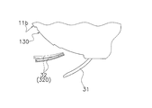
- wing of the air-conditioning indoor unit which concerns on a modification.
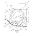
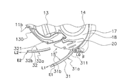
- FIG. 1 is a cross-sectional view of the air conditioning indoor unit 10 when operation is stopped according to an embodiment of the present invention.
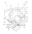
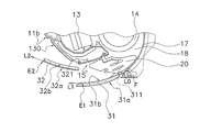
- FIG. 2 is a cross-sectional view of the air conditioning indoor unit 10 during operation. 1 and 2, the air conditioning indoor unit 10 is a wall-hanging type, and a main body casing 11, an indoor heat exchanger 13, an indoor fan 14, a bottom frame 16, and a control unit 40 are mounted thereon.
- the main body casing 11 has a top surface portion 11a, a front panel 11b, a back plate 11c, and a lower horizontal plate 11d, and houses an indoor heat exchanger 13, an indoor fan 14, a bottom frame 16, and a control unit 40 therein. .
- the top surface part 11a is located in the upper part of the main body casing 11, and the inlet (not shown) is provided in the front part of the top surface part 11a.
- the front panel 11b constitutes the front part of the indoor unit, and has a flat shape without a suction port. Further, the upper end of the front panel 11b is rotatably supported by the top surface portion 11a, and can operate in a hinged manner.
- the indoor heat exchanger 13 and the indoor fan 14 are attached to the bottom frame 16.
- the indoor heat exchanger 13 exchanges heat with the passing air.
- the indoor heat exchanger 13 has an inverted V-shape in which both ends are bent downward in a side view, and the indoor fan 14 is located below the indoor heat exchanger 13.
- the indoor fan 14 is a cross-flow fan, blows air taken in from the room against the indoor heat exchanger 13 and then blows it into the room.
- An air outlet 15 is provided at the lower part of the main body casing 11.
- a wind direction adjusting blade 31 that changes the direction of the blown air blown from the blower outlet 15 is rotatably attached to the blower outlet 15.
- the wind direction adjusting blade 31 is driven by a motor (not shown) and can change the direction of the blown air, and can also open and close the blowout port 15.
- the wind direction adjusting blade 31 can take a plurality of postures having different inclination angles.
- a Coanda blade 32 is provided in the vicinity of the air outlet 15.
- the Coanda blade 32 can take a posture inclined in the front-rear direction by a motor (not shown), and is accommodated in the accommodating portion 130 provided in the front panel 11b when the operation is stopped.
- the Coanda blade 32 can take a plurality of postures having different inclination angles. Further, the air outlet 15 is connected to the inside of the main body casing 11 by the air outlet channel 18. The blowout channel 18 is formed along the scroll 17 of the bottom frame 16 from the blowout port 15.
- the indoor air is sucked into the indoor fan 14 through the suction port and the indoor heat exchanger 13 by the operation of the indoor fan 14, and blown out from the blower outlet 15 through the blowout passage 18 from the indoor fan 14.
- the control unit 40 is located on the right side of the indoor heat exchanger 13 and the indoor fan 14 when the main body casing 11 is viewed from the front panel 11b, and controls the rotational speed of the indoor fan 14, the wind direction adjusting blade 31 and the Coanda blade 32. Perform motion control.
- the depth of the depression in this region is set so as to match the thickness dimension of the Coanda blade 32, and constitutes a housing portion 130 in which the Coanda blade 32 is housed.
- the surface of the accommodating part 130 is also a gentle circular curved surface.
- the blower outlet 15 is formed in the lower part of the main body casing 11, and is a rectangular opening which makes a horizontal direction (direction orthogonal to the paper surface of FIG. 1) a long side.
- the lower end of the blower outlet 15 is in contact with the front edge of the lower horizontal plate 11d, and the virtual plane connecting the lower end and the upper end of the blower outlet 15 is inclined forward and upward.
- Scroll 17 The scroll 17 is a partition wall curved so as to face the indoor fan 14 and is a part of the bottom frame 16.
- the end F of the scroll 17 reaches the vicinity of the periphery of the air outlet 15.
- the air passing through the blowout flow path 18 travels along the scroll 17 and is sent in the tangential direction of the end F of the scroll 17. Therefore, if there is no wind direction adjusting blade 31 at the air outlet 15, the air direction of the air blown out from the air outlet 15 is a direction substantially along the tangent L 0 of the terminal end F of the scroll 17.
- the vertical wind direction adjusting plate 20 includes a plurality of blade pieces 201 and a connecting rod 203 that connects the plurality of blade pieces 201. Further, the vertical air direction adjusting plate 20 is disposed nearer the indoor fan 14 than the air direction adjusting blades 31 in the blowout flow path 18. The plurality of blade pieces 201 swing left and right around a state perpendicular to the longitudinal direction as the connecting rod 203 horizontally reciprocates along the longitudinal direction of the outlet 15. The connecting rod 203 is horizontally reciprocated by a motor (not shown). (2-5) Wind direction adjusting blade 31 The wind direction adjusting blade 31 has an area that can block the air outlet 15.
- the outer side surface 31 a is finished to have a gentle circular curved surface that protrudes outwardly as if it is an extension of the curved surface of the front panel 11 b. Further, the inner side surface 31b (see FIG. 2) of the wind direction adjusting blade 31 also forms an arcuate curved surface substantially parallel to the outer surface.
- the wind direction adjusting blade 31 has a rotation shaft 311 at the lower end.
- the rotating shaft 311 is connected to the rotating shaft of a stepping motor (not shown) fixed to the main body casing 11 in the vicinity of the lower end of the air outlet 15.
- the rotation shaft 311 rotates counterclockwise when viewed from the front in FIG. 1, so that the upper end of the airflow direction adjusting blade 31 moves away from the upper end side of the outlet 15 to open the outlet 15.
- the rotation shaft 311 rotates in the clockwise direction in FIG. 1, the upper end of the wind direction adjusting blade 31 operates so as to approach the upper end side of the outlet 15 to close the outlet 15.
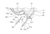
- the Coanda blade 32 is stored in the storage unit 130 while the air-conditioning operation is stopped or in an operation in the normal blowing mode described later.
- the Coanda blade 32 moves away from the accommodating portion 130 by rotating.
- the rotation shaft 321 of the Coanda blade 32 is provided in the vicinity of the lower end of the housing portion 130 and inside the main body casing 11 (a position above the upper wall of the outlet flow passage 18).
- the rotating shaft 321 is connected with a predetermined interval. Therefore, as the rotation shaft 321 rotates and the Coanda blade 32 moves away from the housing portion 130 on the front surface of the casing, the height position of the lower end of the Coanda blade 32 rotates so as to become lower.
- the inclination when the Coanda blade 32 rotates and opens is gentler than the inclination of the casing front surface portion.
- the accommodating portion 130 is provided outside the air passage, and the entire Coanda blade 32 is accommodated outside the air passage when being accommodated.
- only a part of the Coanda blade 32 may be accommodated outside the air passage, and the rest may be accommodated in the air passage (for example, the upper wall portion of the air passage).
- the rotating shaft 321 rotates counterclockwise in the front view of FIG. 1, the upper and lower ends of the Coanda blades 32 are separated from the housing portion 130 while drawing an arc.
- the shortest distance between the casing front portion and the accommodating portion 130 is larger than the shortest distance between the lower end and the accommodating portion 130. That is, the Coanda blade 32 is controlled so as to move away from the front surface of the casing as it goes forward.
- the rotation shaft 321 rotates in the clockwise direction in the front view of FIG. 1
- the Coanda blade 32 approaches the storage unit 130 and is finally stored in the storage unit 130.
- the operating state of the Coanda blade 32 includes a state where the Coanda blade 32 is housed in the storage unit 130, a posture rotated and tilted forward and upward, a posture rotated and substantially horizontal, and a posture rotated and tilted forward and downward. is there.
- the outer surface 32a of the Coanda blade 32 is finished to a gentle circular curved surface that protrudes outwardly as if it is an extension of the gentle circular curved surface of the front panel 11b.
- the inner side surface 32 b of the Coanda blade 32 is finished to have an arcuate curved surface that follows the surface of the housing portion 130.
- the dimension in the longitudinal direction of the Coanda blade 32 is set to be equal to or larger than the dimension in the longitudinal direction of the wind direction adjusting blade 31.
- the reason for this is to receive all of the blown air whose wind direction has been adjusted by the wind direction adjusting blade 31 by the Coanda blade 32, and its purpose is to prevent the blown air from the side of the Coanda blade 32 from short-circuiting.
- Direction control of blown air The air-conditioning indoor unit of the present embodiment, as means for controlling the direction of blown air, is a normal blow mode that adjusts the direction of blown air by rotating only the wind direction adjusting blade 31 and the wind direction.
- the adjustment blade 31 and the Coanda blade 32 are rotated so that the Coanda effect uses the Coanda effect to make the blown air flow along the outer surface 32a of the Coanda blade 32, and the tips of the wind direction adjustment blade 31 and the Coanda blade 32, respectively.
- FIG. 3A is a side view of the wind direction adjusting blade 31 and the Coanda blade 32 when the blown air is normally forward blown. In FIG.
- the control unit 40 rotates the wind direction adjusting blade 31 to a position where the inner side surface 31b of the wind direction adjusting blade 31 becomes substantially horizontal.
- wing 31 has comprised the circular arc curved surface like this embodiment, the wind direction adjustment blade
- FIG. 3B is a side view of the wind direction adjusting blade 31 and the Coanda blade 32 when the blown air is normally forward down blown.
- the control unit 40 rotates the wind direction adjusting blade 31 until the tangent at the front end E1 of the inner side surface 31b of the wind direction adjusting blade 31 becomes lower than the horizontal. As a result, the blown air is in a front lower blowing state.
- Coanda (effect) means that if there is a wall near the flow of gas or liquid, it flows in the direction along the wall surface even if the direction of the flow is different from the direction of the wall. It is a phenomenon to try (Asakura Shoten “Dictionary of Law”).
- the Coanda utilization mode includes “Coanda airflow front blowing” and “Coanda airflow ceiling blowing” using this Coanda effect.
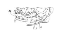
- FIG. 4A is a conceptual diagram showing the direction of blown air and the direction of Coanda airflow.
- the inclination of the blown air direction (D1) changed by the wind direction adjusting blade 31 is close to the posture (inclination) of the Coanda blade 32. There is a need. If they are too far apart, the Coanda effect will not occur.
- the Coanda blade 32 and the wind direction adjusting blade 31 need to be equal to or less than a predetermined opening angle, and both the adjustment plates (31, 32) are within the range, and The relationship is established. Thereby, as shown in FIG. 4A, after the wind direction of the blown air is changed to D1 by the wind direction adjusting blade 31, it is further changed to D2 by the Coanda effect.
- FIG. 4B is a conceptual diagram illustrating an example of an opening angle between the wind direction adjusting blade 31 and the Coanda blade 32.
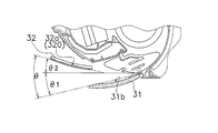
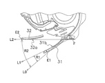
- the wind direction adjusting blade 31 and the Coanda blade 32 have an inner angle formed by the tangent of the end F of the scroll 17 and the Coanda blade 32 and the tangent of the end F of the scroll 17. It is preferable to take a posture that satisfies the condition that it is larger than the inner angle formed by the wind direction adjusting blade 31. 5A (the inner angle R2 formed by the tangent line L0 of the terminal end F of the scroll 17 and the Coanda blade 32 when the Coanda airflow is blown forward and the tangent line L0 of the terminal end F of the scroll 17 and the airflow direction adjusting blade 31 are formed.
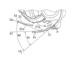
- Comparison diagram with inner angle R1) and FIG. 5B inner angle R2 formed between tangent L0 of end F of scroll 17 and Coanda blade 32 when Coanda airflow ceiling is blown, tangent L0 of end F of scroll 17 and wind direction adjusting blade 31) (Refer to the comparison figure with the internal angle R1).
- 3C is a side view of the wind direction adjusting blade 31 and the Coanda blade 32 during the Coanda airflow forward blow.
- the control unit 40 moves the airflow direction adjustment blade 31 until the tangent L1 at the front end E1 of the inner side surface 31b of the airflow direction adjustment blade 31 becomes lower than the horizontal. Rotate.
- the control unit 40 rotates the Coanda blade 32 until the outer surface 32a of the Coanda blade 32 becomes substantially horizontal.
- the Coanda blade 32 is rotated until the tangent L2 at the front end E2 of the outer surface 32a becomes substantially horizontal. That is, as shown in FIG. 5A, the inner angle R2 formed by the tangent line L0 and the tangent line L2 is larger than the inner angle R1 formed by the tangent line L0 and the tangent line L1.
- the blown air adjusted to the front lower blow by the wind direction adjusting blade 31 becomes a flow attached to the outer surface 32a of the Coanda blade 32 by the Coanda effect, and changes to a Coanda airflow along the outer surface 32a. Therefore, even if the tangential L1 direction at the front end E1 of the airflow direction adjusting blade 31 is the front lower blowing, the tangential L2 direction at the front end E2 of the Coanda blade 32 is horizontal, so that the blown air is blown from the Coanda blade 32 by the Coanda effect. It blows off in the tangent L2 direction at the front end E2 of the outer side surface 32a, that is, in the horizontal direction.
- FIG. 3D is a side view of the wind direction adjusting blade 31 and the Coanda blade 32 when the Coanda airflow ceiling is blown.
- the control unit 40 rotates the airflow direction adjusting blade 31 until the tangent L1 at the front end E1 of the inner side surface 31b of the airflow direction adjusting blade 31 becomes horizontal.
- the control part 40 rotates the Coanda blade
- the blown air adjusted to be blown horizontally by the wind direction adjusting blade 31 becomes a flow attached to the outer surface 32a of the Coanda blade 32 by the Coanda effect, and changes to a Coanda airflow along the outer surface 32a.
- the tangential L2 direction at the front end E2 of the Coanda blade 32 is forward upward blowing, so that the blown air is generated by the Coanda effect by the Coanda effect. It blows out in the tangent L2 direction at the front end E2 of the outer side surface 32a, that is, the ceiling direction. Since the front end portion of the Coanda blade 32 protrudes outward from the air outlet 15, the Coanda airflow reaches further away. Further, since the tip of the Coanda blade 32 is positioned above the outlet 15, the wind is prevented from traveling straightly downward along the scroll 17 on the upper side of the Coanda blade 32. The upward induction of is difficult to be inhibited.
- the Coanda blades 32 are separated from the casing front surface and the inclination becomes gentle, and the blown air becomes more susceptible to the Coanda effect in front of the front panel 11b.
- the blown air whose wind direction is adjusted by the wind direction adjusting blade 31 is forward blowing, it becomes upward air due to the Coanda effect.
- the wind direction is changed while the pressure loss due to the ventilation resistance of the wind direction adjusting blade 31 is suppressed.
- the blown air is guided toward the ceiling while the blower outlet 15 remains open. That is, the blown air is guided toward the ceiling in a state where the ventilation resistance is kept low.
- the size in the longitudinal direction of the Coanda blade 32 is not less than the size in the longitudinal direction of the wind direction adjusting blade 31. Therefore, all of the blown air whose wind direction is adjusted by the wind direction adjusting blade 31 can be received by the Coanda blade 32, and the effect that the blown air is prevented from short-circuiting from the side of the Coanda blade 32 is also achieved.
- FIG. 3E is a side view of the wind direction adjusting blade 31 and the Coanda blade 32 during the down-blowing.
- the control unit 40 rotates the wind direction adjusting blade 31 until the tangent at the front end E1 of the inner side surface 31b of the wind direction adjusting blade 31 is directed downward.
- the control part 40 rotates the Coanda blade
- the blown air passes between the wind direction adjusting blade 31 and the Coanda blade 32 and is blown downward.
- control unit 40 executes the down blowing mode to apply a downward air flow against the outer surface 32 a of the Coanda blade 32. Can be generated.
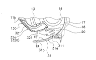
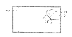
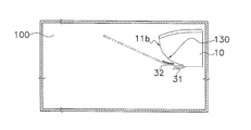
- FIG. 6A is a side view of the air-conditioning indoor unit installation space showing the wind direction of the Coanda airflow when the Coanda blade 32 takes the first posture.
- the air conditioning indoor unit 10 is installed above the indoor side wall.
- the Coanda blade 32 is in a state of being housed in the housing portion 130 (hereinafter referred to as a first posture).
- the air direction adjustment blade 31 is made to face upward from the horizontal so that the blown air whose air direction has been adjusted on the inner surface 31b of the wind direction adjustment blade 31 leaves the inner surface 31b.
- the direction is changed so as to be pulled by the outer surface 32a of the Coanda blade 32, and the first Coanda airflow flows along the outer surface 32a of the Coanda blade 32 and the front panel 11b.
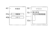
- FIG. 7A is a block diagram showing the relationship between the control unit 40 and the remote controller 50.
- the remote controller 50 transmits an infrared signal wirelessly.
- the remote controller 50 has switching means for switching the wind direction. Specifically, it has a display unit 52 that displays a wind direction selection menu and a cursor 52a for designating each wind direction selection menu so that the user can select the wind direction.
- the user selects “Coanda wind direction setting” from the menu displayed on the display unit 52 with the cursor 52a. Since the technology for selecting and confirming the menu by the remote controller 50 is widely disclosed, detailed description is omitted.
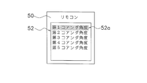
- FIG. 7B is a front view of the display unit 52 showing a lower menu of the “Coanda wind direction setting” menu.
- the first to fifth Coanda angles are prepared in advance in the lower menu of the “Coanda wind direction setting” menu.
- the Coanda blade 32 is displayed.
- the first posture shown in FIG. 6A is taken, and a Coanda airflow in a first direction corresponding to the first Coanda angle is generated.
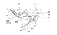
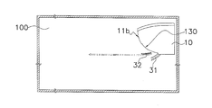
- FIG. 6B is a side view of the air conditioning indoor unit installation space showing the wind direction of the Coanda airflow when the Coanda blade 32 takes the second posture. .
- the second posture of the Coanda blade 32 in FIG. 6B can be achieved by specifying and confirming the second Coanda angle with the cursor 52a in FIG. 7B.
- the Coanda airflow generated when the Coanda blade 32 is in the second posture corresponds to the Coanda airflow described in the section “(3-2-2) Coanda airflow ceiling blowing”.
- the control unit 40 rotates the wind direction adjusting blade 31 until the tangent L1 at the front end E1 of the inner side surface 31b of the wind direction adjusting blade 31 becomes horizontal, Next, the Coanda blade 32 is rotated until the tangent L2 at the front end E2 of the outer side surface 32a is directed upward.
- FIG. 8A is a side view of the wind direction adjusting blade 31 and the Coanda blade 32 when the Coanda blade 32 is in the third posture.
- the third posture of the Coanda blade 32 is downward than the second posture.
- the Coanda blade 32 in the second posture is drawn with a two-dot chain line
- the Coanda blade 32 in the third posture is drawn with a solid line.
- the Coanda airflow is reliably generated in the second posture and the posture of the airflow direction adjusting blade 31 is not changed, the Coanda airflow is directed from the outer surface 32a of the Coanda blade 32 in the third posture that is downward than the second posture. It is clear that it does not peel.
- it can be achieved by selecting the second Coanda angle or the third Coanda angle with the cursor 52a in FIG. 7B.
- the blown air is adjusted by the wind direction adjusting blade 31 in a direction approaching the curved surface 320 of the Coanda blade 32, and the Coanda blade 32 uses the blown air whose air direction is adjusted as its own. Since the air flow is changed to the Coanda airflow along the curved surface 320, the wind direction deflection effect is great.
- the tip of the Coanda blade 32 faces the ceiling, so the Coanda airflow along the curved surface 320 of the Coanda blade 32 is separated from the front panel 11b and You can go upward. In this case, even if there is a suction port above the front surface of the main body casing 11, a short circuit can be prevented.
- the second posture and the third posture of the Coanda blade 32 are selected when it is desired to fly conditioned air far away.
- the Coanda blade 32 is preferably in the second posture.
- the posture of the Coanda blade 32 is preferably the third posture.
- the user can select the posture of the Coanda blade 32 according to the size of the indoor space via the remote controller 50, so that the user can use the conditioned air evenly in the air-conditioning target space. Is possible.
- the outer surface 32a of the Coanda blade 32 may be a convexly curved shape or a planar shape.
- the outer surface 32a is preferably convexly curved in the following points.
- the outer surface 32 a of the Coanda blade 32 is curved in a convex shape to form a curved surface 320. Since the Coanda blade 32 moves away from the front panel 11b as it moves away from the outlet 15, the Coanda airflow along the curved surface 320 of the Coanda blade 32 advances upward while leaving the front panel 11b. be able to. Further, the angle of the tip of the Coanda blade 32 becomes an upward angle, and an upward airflow can be generated without making the inclination angle of the Coanda blade sharp.
- FIG. 6C is a side view of the air-conditioning indoor unit installation space showing the wind direction of the Coanda airflow when the Coanda blade 32 takes the fourth posture.
- 6C can be comprised by specifying and confirming a 4th Coanda angle with the cursor 52a in FIG. 7B.
- the Coanda airflow generated when the Coanda blade 32 is in the fourth posture corresponds to the Coanda airflow described in the section “(3-2-1) Coanda airflow forward blowing”.
- the controller 40 adjusts the wind direction adjusting blade 31 until the tangent line L1 at the front end E1 of the inner side surface 31b of the wind direction adjusting blade 31 becomes lower than the horizontal.
- the Coanda blade 32 is rotated until the outer surface 32a of the Coanda blade 32 becomes substantially horizontal.
- the tangential L1 direction at the front end E1 of the airflow direction adjusting blade 31 is the front lower blowing
- the tangential L2 direction at the front end E2 of the Coanda blade 32 is horizontal, so that the blown air is blown from the Coanda blade 32 by the Coanda effect. It blows off in the tangent L2 direction at the front end E2 of the outer side surface 32a, that is, in the horizontal direction.
- FIG. 8B is a side view of the wind direction adjusting blade 31 and the Coanda blade 32 when the Coanda blade 32 is in the fifth posture.
- the fifth posture of the Coanda blade 32 is more downward than the fourth posture.
- the Coanda blade 32 in the fourth posture is drawn with a two-dot chain line and the Coanda blade 32 in the fifth posture is drawn with a solid line for comparison.
- the Coanda airflow is reliably generated in the fourth posture and the posture of the wind direction adjusting blade 31 is not changed, the Coanda airflow is directed from the outer surface 32a of the Coanda blade 32 in the fifth posture, which is downward than the fourth posture. It is clear that it does not peel.
- it can be achieved by selecting the fourth Coanda angle or the fifth Coanda angle with the cursor 52a in FIG. 7B.
- the attitude of the wind direction adjusting vane 31 is different from each of the first attitude, the second attitude, and the fourth attitude of the Coanda vane 32.
- the Coanda airflow by the Coanda blade 32 can be directed in any direction by a combination of the posture of the wind direction adjusting blade 31 and the posture of the Coanda blade 32.
- a curved surface 320 that is curved in a convex shape is formed on the outer surface 32 a of the Coanda blade 32.
- the Coanda blade 32 moves away from the casing front face as it moves away from the air outlet 15, the Coanda airflow along the curved surface 320 of the Coanda blade 32 advances upward while leaving the casing front face. be able to.
- the angle of the tip of the Coanda blade 32 is an upward angle, and an upward airflow can be generated without making the inclination angle of the Coanda blade 32 abrupt.
- a housing part 130 in which the Coanda blade 32 is housed is formed on the front surface of the casing.
- the Coanda blade 32 is housed in the housing portion 130, and the front surface portion of the casing and the curved surface 320 of the Coanda blade 32 are curved so as to be aligned on one continuous virtual curved surface. Therefore, the appearance of the front portion of the casing when the Coanda blade 32 is accommodated is good, and the deterioration of the design is suppressed.
- the curved surface 320 of the Coanda blade 32 is formed of a plurality of curved surfaces 320 having different degrees of curvature.
- the degree of deflection from the direction of the blown air to the direction of the Coanda airflow can be increased while suppressing the Coanda airflow from being separated from the curved surface 320.
- the control unit 40 controls the postures of the wind direction adjusting blade 31 and the Coanda blade 32 when changing the direction of the Coanda airflow.
- the wind direction adjusting blade 31 adjusts the blowing air in a direction approaching the curved surface 320 of the Coanda blade 32, and the Coanda blade 32 changes the blown air whose wind direction is adjusted to the Coanda airflow along its own curved surface 320.
- Great deflection effect (5-7)
- the control unit 40 adjusts the posture of the Coanda blade 32 so that the rear end portion of the Coanda blade 32 faces downward and the front end portion faces upward.
- the curved surface 320 of the Coanda blade 32 is formed as a single curved surface, but may be formed from a plurality of curved surfaces having different degrees of curvature.
- FIG. 9 is a side view of the Coanda blade 32 of the air conditioning indoor unit 10 according to the modification.
- the curved surface 320 of the Coanda blade 32 is formed by three circular arc surfaces having a radius X, a radius Y, and a radius Z.
- the present invention is useful for a wall-mounted air conditioning indoor unit.
Landscapes
- Engineering & Computer Science (AREA)
- Chemical & Material Sciences (AREA)
- Combustion & Propulsion (AREA)
- Mechanical Engineering (AREA)
- General Engineering & Computer Science (AREA)
- Air-Flow Control Members (AREA)
- Air Conditioning Control Device (AREA)
- Air Filters, Heat-Exchange Apparatuses, And Housings Of Air-Conditioning Units (AREA)
Abstract
Priority Applications (9)
| Application Number | Priority Date | Filing Date | Title |
|---|---|---|---|
| BR112014010240A BR112014010240A2 (pt) | 2011-10-31 | 2012-10-02 | unidade interna de ar condicionado |
| SG11201401920XA SG11201401920XA (en) | 2011-10-31 | 2012-10-02 | Air-conditioning indoor unit |
| KR1020147014189A KR101429427B1 (ko) | 2011-10-31 | 2012-10-02 | 공조 실내기 |
| IN1027KON2014 IN2014KN01027A (fr) | 2011-10-31 | 2012-10-02 | |
| ES12846065.6T ES2653587T3 (es) | 2011-10-31 | 2012-10-02 | Unidad de interior de acondicionamiento de aire |
| CN201280053268.0A CN103906981B (zh) | 2011-10-31 | 2012-10-02 | 空调室内机 |
| AU2012333903A AU2012333903C1 (en) | 2011-10-31 | 2012-10-02 | Air-conditioning indoor unit |
| EP12846065.6A EP2778551B1 (fr) | 2011-10-31 | 2012-10-02 | Unité de climatisation d'intérieur |
| US14/354,896 US9488381B2 (en) | 2011-10-31 | 2012-10-02 | Air-conditioning indoor unit |
Applications Claiming Priority (2)
| Application Number | Priority Date | Filing Date | Title |
|---|---|---|---|
| JP2011-239778 | 2011-10-31 | ||
| JP2011239778A JP5408227B2 (ja) | 2011-10-31 | 2011-10-31 | 空調室内機 |
Publications (1)
| Publication Number | Publication Date |
|---|---|
| WO2013065438A1 true WO2013065438A1 (fr) | 2013-05-10 |
Family
ID=48191796
Family Applications (1)
| Application Number | Title | Priority Date | Filing Date |
|---|---|---|---|
| PCT/JP2012/075462 WO2013065438A1 (fr) | 2011-10-31 | 2012-10-02 | Unité de climatisation d'intérieur |
Country Status (12)
| Country | Link |
|---|---|
| US (1) | US9488381B2 (fr) |
| EP (1) | EP2778551B1 (fr) |
| JP (1) | JP5408227B2 (fr) |
| KR (1) | KR101429427B1 (fr) |
| CN (1) | CN103906981B (fr) |
| AU (1) | AU2012333903C1 (fr) |
| BR (1) | BR112014010240A2 (fr) |
| ES (1) | ES2653587T3 (fr) |
| IN (1) | IN2014KN01027A (fr) |
| MY (1) | MY169353A (fr) |
| SG (1) | SG11201401920XA (fr) |
| WO (1) | WO2013065438A1 (fr) |
Cited By (2)
| Publication number | Priority date | Publication date | Assignee | Title |
|---|---|---|---|---|
| CN107300210A (zh) * | 2016-04-01 | 2017-10-27 | 珠海格力电器股份有限公司 | 空调室内机 |
| JP7082293B2 (ja) | 2019-09-17 | 2022-06-08 | ダイキン工業株式会社 | 空調室内機および空気調和機 |
Families Citing this family (21)
| Publication number | Priority date | Publication date | Assignee | Title |
|---|---|---|---|---|
| JP5365675B2 (ja) * | 2011-09-30 | 2013-12-11 | ダイキン工業株式会社 | 空調室内機 |
| JP5403125B2 (ja) * | 2011-10-31 | 2014-01-29 | ダイキン工業株式会社 | 空調室内機 |
| WO2015058546A1 (fr) | 2013-10-25 | 2015-04-30 | 优视科技有限公司 | Procede et dispositif de prechargement de page web |
| CN104329786B (zh) * | 2014-09-18 | 2018-04-27 | 青岛海尔空调器有限总公司 | 空气处理系统的顶盖 |
| WO2016133261A1 (fr) * | 2015-02-18 | 2016-08-25 | 삼성전자주식회사 | Climatiseur |
| CN106152436B (zh) * | 2015-04-17 | 2019-04-12 | 青岛海尔空调电子有限公司 | 一种卡式空调及其导风装置 |
| JP2017040408A (ja) * | 2015-08-18 | 2017-02-23 | ジョンソンコントロールズ ヒタチ エア コンディショニング テクノロジー(ホンコン)リミテッド | 空気調和機 |
| JP2018084368A (ja) * | 2016-11-24 | 2018-05-31 | 株式会社富士通ゼネラル | 空気調和機の室内機 |
| CN106907829A (zh) * | 2017-02-28 | 2017-06-30 | 广东美的制冷设备有限公司 | 一种室内机制热控制方法、控制装置及空调 |
| FR3065791A1 (fr) * | 2017-05-01 | 2018-11-02 | Eric Convoi Nelson | Deflecteur d'air, recyclant, pour climatiseurs de types mural et plafonnier (unites interieures). |
| CN111295554B (zh) * | 2017-09-06 | 2021-10-29 | Lg电子株式会社 | 空调机的天花板式室内机 |
| WO2019050309A1 (fr) * | 2017-09-06 | 2019-03-14 | 엘지전자 주식회사 | Unité intérieure de plafond pour climatiseur |
| WO2019050308A1 (fr) * | 2017-09-06 | 2019-03-14 | 엘지전자 주식회사 | Unité intérieure du type pour plafond de climatiseur |
| WO2019050307A1 (fr) * | 2017-09-06 | 2019-03-14 | 엘지전자 주식회사 | Unité intérieure de type plafond de climatiseur |
| EP4321816A2 (fr) * | 2017-09-20 | 2024-02-14 | LG Electronics Inc. | Unité intérieure de climatiseur de type plafond |
| JP6515968B2 (ja) * | 2017-09-27 | 2019-05-22 | ダイキン工業株式会社 | 空調室内機 |
| KR102508191B1 (ko) * | 2017-11-10 | 2023-03-09 | 삼성전자주식회사 | 공기조화기 |
| CN114391080A (zh) * | 2019-09-17 | 2022-04-22 | 大金工业株式会社 | 空调室内机 |
| JP6849032B2 (ja) * | 2019-09-17 | 2021-03-24 | ダイキン工業株式会社 | 空調室内機および空気調和機 |
| JP6897735B2 (ja) * | 2019-09-17 | 2021-07-07 | ダイキン工業株式会社 | 空調室内機および空気調和機 |
| JP7025672B2 (ja) * | 2019-09-17 | 2022-02-25 | ダイキン工業株式会社 | 空調室内機 |
Citations (7)
| Publication number | Priority date | Publication date | Assignee | Title |
|---|---|---|---|---|
| JPH109659A (ja) | 1996-06-26 | 1998-01-16 | Toshiba Corp | 空気調和機 |
| JP2003232531A (ja) | 2002-02-06 | 2003-08-22 | Sharp Corp | 空気調和機 |
| JP2004361011A (ja) * | 2003-06-05 | 2004-12-24 | Hitachi Home & Life Solutions Inc | 空気調和機 |
| JP2007051866A (ja) * | 2006-09-11 | 2007-03-01 | Sharp Corp | 空気調和機 |
| JP2009097755A (ja) * | 2007-10-15 | 2009-05-07 | Mitsubishi Electric Corp | 空気調和機 |
| JP2011214727A (ja) * | 2010-03-31 | 2011-10-27 | Hitachi Appliances Inc | 空気調和機 |
| JP2012197970A (ja) * | 2011-03-22 | 2012-10-18 | Panasonic Corp | 空気調和機 |
Family Cites Families (17)
| Publication number | Priority date | Publication date | Assignee | Title |
|---|---|---|---|---|
| US4350472A (en) * | 1978-11-14 | 1982-09-21 | Sanyo Electric Co., Ltd. | Electric fan apparatus |
| AU583505B2 (en) * | 1984-05-10 | 1989-05-04 | Matsushita Electric Industrial Co., Ltd. | Flow deflecting assembly |
| JP2993412B2 (ja) * | 1995-11-20 | 1999-12-20 | 三菱電機株式会社 | 吹出口及び該吹出口を備えた空気調和装置 |
| US5762034A (en) * | 1996-01-16 | 1998-06-09 | Board Of Trustees Operating Michigan State University | Cooling fan shroud |
| JP3302906B2 (ja) * | 1997-07-15 | 2002-07-15 | 三菱電機株式会社 | 空気調和装置 |
| JP3669322B2 (ja) * | 2000-11-21 | 2005-07-06 | ダイキン工業株式会社 | 空気調和機の室内機 |
| JP4017483B2 (ja) * | 2002-09-25 | 2007-12-05 | シャープ株式会社 | 空気調和機 |
| JP3686963B2 (ja) * | 2003-11-28 | 2005-08-24 | シャープ株式会社 | 空気調和機 |
| JP2005188847A (ja) * | 2003-12-26 | 2005-07-14 | Fujitsu General Ltd | 空気調和機 |
| JP4991365B2 (ja) | 2007-03-29 | 2012-08-01 | カヤバ工業株式会社 | 寸法測定装置及び寸法測定方法 |
| EP2149465B1 (fr) * | 2008-07-31 | 2010-09-15 | C.R.F. Società Consortile per Azioni | Tableau de bord de véhicule à moteur doté d'une portion centrale principale dépourvue d'orifices pour la ventilation d'air |
| US20110010958A1 (en) * | 2009-07-16 | 2011-01-20 | Wayne Clark | Quiet hair dryer |
| CN102207327A (zh) * | 2010-03-31 | 2011-10-05 | 日立空调·家用电器株式会社 | 空调机 |
| US20120168117A1 (en) * | 2011-01-04 | 2012-07-05 | Automotive Components Holdings, Llc | Automotive HVAC Diffuser With Cooperating Wall Guide And Vane |
| JP5120482B1 (ja) * | 2011-07-01 | 2013-01-16 | ダイキン工業株式会社 | 空調室内機 |
| DE102012008264A1 (de) * | 2012-04-25 | 2013-10-31 | Airbus Operations Gmbh | Passagierservicesystem mit verbesserter Luftführung |
| JP6015902B2 (ja) * | 2012-05-09 | 2016-10-26 | スズキ株式会社 | 車両の送風構造 |
-
2011
- 2011-10-31 JP JP2011239778A patent/JP5408227B2/ja active Active
-
2012
- 2012-10-02 BR BR112014010240A patent/BR112014010240A2/pt not_active Application Discontinuation
- 2012-10-02 KR KR1020147014189A patent/KR101429427B1/ko not_active IP Right Cessation
- 2012-10-02 CN CN201280053268.0A patent/CN103906981B/zh active Active
- 2012-10-02 EP EP12846065.6A patent/EP2778551B1/fr active Active
- 2012-10-02 SG SG11201401920XA patent/SG11201401920XA/en unknown
- 2012-10-02 AU AU2012333903A patent/AU2012333903C1/en active Active
- 2012-10-02 WO PCT/JP2012/075462 patent/WO2013065438A1/fr active Application Filing
- 2012-10-02 IN IN1027KON2014 patent/IN2014KN01027A/en unknown
- 2012-10-02 US US14/354,896 patent/US9488381B2/en active Active
- 2012-10-02 ES ES12846065.6T patent/ES2653587T3/es active Active
- 2012-10-02 MY MYPI2014700856A patent/MY169353A/en unknown
Patent Citations (7)
| Publication number | Priority date | Publication date | Assignee | Title |
|---|---|---|---|---|
| JPH109659A (ja) | 1996-06-26 | 1998-01-16 | Toshiba Corp | 空気調和機 |
| JP2003232531A (ja) | 2002-02-06 | 2003-08-22 | Sharp Corp | 空気調和機 |
| JP2004361011A (ja) * | 2003-06-05 | 2004-12-24 | Hitachi Home & Life Solutions Inc | 空気調和機 |
| JP2007051866A (ja) * | 2006-09-11 | 2007-03-01 | Sharp Corp | 空気調和機 |
| JP2009097755A (ja) * | 2007-10-15 | 2009-05-07 | Mitsubishi Electric Corp | 空気調和機 |
| JP2011214727A (ja) * | 2010-03-31 | 2011-10-27 | Hitachi Appliances Inc | 空気調和機 |
| JP2012197970A (ja) * | 2011-03-22 | 2012-10-18 | Panasonic Corp | 空気調和機 |
Non-Patent Citations (3)
| Title |
|---|
| "Press Release Room Air Conditioner X Series o Hatsubai", 6 September 2011 (2011-09-06), XP055135824, Retrieved from the Internet <URL:http://panasonic.co.jp/corp/news/official. data/data.dir/jn110906-1/jn110906-1.html> * |
| PANASONIC CORP.: "AIR CONDITIONER TOKUSEN PAMPHLET S X SERIES", 1 October 2011 (2011-10-01), pages 5, 6, 10, 11, XP008172374 * |
| PANASONIC CORP.: "TORIATSUKAI SETSUMEISHO", 21 October 2011 (2011-10-21), pages 1, 6 - 8, 12, 13, 32 TO 37, 52, XP055135825, Retrieved from the Internet <URL:http://dl-ctlg. panasonic.jp/manual/cs/cs_12x_22_56_02.pdf> * |
Cited By (3)
| Publication number | Priority date | Publication date | Assignee | Title |
|---|---|---|---|---|
| CN107300210A (zh) * | 2016-04-01 | 2017-10-27 | 珠海格力电器股份有限公司 | 空调室内机 |
| CN107300210B (zh) * | 2016-04-01 | 2020-10-02 | 珠海格力电器股份有限公司 | 空调室内机 |
| JP7082293B2 (ja) | 2019-09-17 | 2022-06-08 | ダイキン工業株式会社 | 空調室内機および空気調和機 |
Also Published As
| Publication number | Publication date |
|---|---|
| US20140308888A1 (en) | 2014-10-16 |
| ES2653587T3 (es) | 2018-02-07 |
| AU2012333903B2 (en) | 2015-09-10 |
| CN103906981A (zh) | 2014-07-02 |
| EP2778551A4 (fr) | 2015-01-07 |
| AU2012333903C1 (en) | 2015-12-24 |
| US9488381B2 (en) | 2016-11-08 |
| BR112014010240A2 (pt) | 2017-04-18 |
| KR20140079511A (ko) | 2014-06-26 |
| SG11201401920XA (en) | 2014-10-30 |
| EP2778551A1 (fr) | 2014-09-17 |
| CN103906981B (zh) | 2015-04-08 |
| AU2012333903A1 (en) | 2014-06-05 |
| IN2014KN01027A (fr) | 2015-10-09 |
| EP2778551B1 (fr) | 2017-07-26 |
| KR101429427B1 (ko) | 2014-08-12 |
| MY169353A (en) | 2019-03-25 |
| JP2013096637A (ja) | 2013-05-20 |
| JP5408227B2 (ja) | 2014-02-05 |
Similar Documents
| Publication | Publication Date | Title |
|---|---|---|
| JP5408227B2 (ja) | 空調室内機 | |
| JP5408228B2 (ja) | 空調室内機 | |
| JP5365675B2 (ja) | 空調室内機 | |
| WO2013065436A1 (fr) | Unité de climatisation d'intérieur | |
| JP5403125B2 (ja) | 空調室内機 | |
| JP5536158B2 (ja) | 空調室内機 | |
| JP5403046B2 (ja) | 空調室内機 | |
| WO2013099914A1 (fr) | Appareil intérieur pour conditionnement d'air | |
| JP5408318B1 (ja) | 空調室内機 | |
| JP5834911B2 (ja) | 空調室内機 | |
| JP5408319B1 (ja) | 空調室内機 | |
| JP5413535B2 (ja) | 空調室内機 | |
| JP5772589B2 (ja) | 空調室内機 | |
| JP5783041B2 (ja) | 空調室内機 |
Legal Events
| Date | Code | Title | Description |
|---|---|---|---|
| 121 | Ep: the epo has been informed by wipo that ep was designated in this application |
Ref document number: 12846065 Country of ref document: EP Kind code of ref document: A1 |
|
| WWE | Wipo information: entry into national phase |
Ref document number: 14354896 Country of ref document: US |
|
| NENP | Non-entry into the national phase |
Ref country code: DE |
|
| REEP | Request for entry into the european phase |
Ref document number: 2012846065 Country of ref document: EP |
|
| WWE | Wipo information: entry into national phase |
Ref document number: 2012846065 Country of ref document: EP |
|
| ENP | Entry into the national phase |
Ref document number: 20147014189 Country of ref document: KR Kind code of ref document: A |
|
| ENP | Entry into the national phase |
Ref document number: 2012333903 Country of ref document: AU Date of ref document: 20121002 Kind code of ref document: A |
|
| REG | Reference to national code |
Ref country code: BR Ref legal event code: B01A Ref document number: 112014010240 Country of ref document: BR |
|
| ENP | Entry into the national phase |
Ref document number: 112014010240 Country of ref document: BR Kind code of ref document: A2 Effective date: 20140429 |