WO2013065438A1 - Air-conditioning indoor unit - Google Patents
Air-conditioning indoor unit Download PDFInfo
- Publication number
- WO2013065438A1 WO2013065438A1 PCT/JP2012/075462 JP2012075462W WO2013065438A1 WO 2013065438 A1 WO2013065438 A1 WO 2013065438A1 JP 2012075462 W JP2012075462 W JP 2012075462W WO 2013065438 A1 WO2013065438 A1 WO 2013065438A1
- Authority
- WO
- WIPO (PCT)
- Prior art keywords
- coanda
- blade
- air
- coanda blade
- indoor unit
- Prior art date
Links
Images


Classifications
-
- F—MECHANICAL ENGINEERING; LIGHTING; HEATING; WEAPONS; BLASTING
- F24—HEATING; RANGES; VENTILATING
- F24F—AIR-CONDITIONING; AIR-HUMIDIFICATION; VENTILATION; USE OF AIR CURRENTS FOR SCREENING
- F24F13/00—Details common to, or for air-conditioning, air-humidification, ventilation or use of air currents for screening
- F24F13/08—Air-flow control members, e.g. louvres, grilles, flaps or guide plates
- F24F13/10—Air-flow control members, e.g. louvres, grilles, flaps or guide plates movable, e.g. dampers
-
- F—MECHANICAL ENGINEERING; LIGHTING; HEATING; WEAPONS; BLASTING
- F24—HEATING; RANGES; VENTILATING
- F24F—AIR-CONDITIONING; AIR-HUMIDIFICATION; VENTILATION; USE OF AIR CURRENTS FOR SCREENING
- F24F11/00—Control or safety arrangements
- F24F11/89—Arrangement or mounting of control or safety devices
-
- F—MECHANICAL ENGINEERING; LIGHTING; HEATING; WEAPONS; BLASTING
- F24—HEATING; RANGES; VENTILATING
- F24F—AIR-CONDITIONING; AIR-HUMIDIFICATION; VENTILATION; USE OF AIR CURRENTS FOR SCREENING
- F24F13/00—Details common to, or for air-conditioning, air-humidification, ventilation or use of air currents for screening
- F24F13/08—Air-flow control members, e.g. louvres, grilles, flaps or guide plates
- F24F13/10—Air-flow control members, e.g. louvres, grilles, flaps or guide plates movable, e.g. dampers
- F24F13/14—Air-flow control members, e.g. louvres, grilles, flaps or guide plates movable, e.g. dampers built up of tilting members, e.g. louvre
-
- F—MECHANICAL ENGINEERING; LIGHTING; HEATING; WEAPONS; BLASTING
- F24—HEATING; RANGES; VENTILATING
- F24F—AIR-CONDITIONING; AIR-HUMIDIFICATION; VENTILATION; USE OF AIR CURRENTS FOR SCREENING
- F24F1/00—Room units for air-conditioning, e.g. separate or self-contained units or units receiving primary air from a central station
- F24F1/0007—Indoor units, e.g. fan coil units
- F24F1/0011—Indoor units, e.g. fan coil units characterised by air outlets
-
- F—MECHANICAL ENGINEERING; LIGHTING; HEATING; WEAPONS; BLASTING
- F24—HEATING; RANGES; VENTILATING
- F24F—AIR-CONDITIONING; AIR-HUMIDIFICATION; VENTILATION; USE OF AIR CURRENTS FOR SCREENING
- F24F1/00—Room units for air-conditioning, e.g. separate or self-contained units or units receiving primary air from a central station
- F24F1/0007—Indoor units, e.g. fan coil units
- F24F1/0043—Indoor units, e.g. fan coil units characterised by mounting arrangements
- F24F1/0047—Indoor units, e.g. fan coil units characterised by mounting arrangements mounted in the ceiling or at the ceiling
-
- F—MECHANICAL ENGINEERING; LIGHTING; HEATING; WEAPONS; BLASTING
- F24—HEATING; RANGES; VENTILATING
- F24F—AIR-CONDITIONING; AIR-HUMIDIFICATION; VENTILATION; USE OF AIR CURRENTS FOR SCREENING
- F24F11/00—Control or safety arrangements
- F24F11/70—Control systems characterised by their outputs; Constructional details thereof
- F24F11/72—Control systems characterised by their outputs; Constructional details thereof for controlling the supply of treated air, e.g. its pressure
- F24F11/79—Control systems characterised by their outputs; Constructional details thereof for controlling the supply of treated air, e.g. its pressure for controlling the direction of the supplied air
-
- F—MECHANICAL ENGINEERING; LIGHTING; HEATING; WEAPONS; BLASTING
- F24—HEATING; RANGES; VENTILATING
- F24F—AIR-CONDITIONING; AIR-HUMIDIFICATION; VENTILATION; USE OF AIR CURRENTS FOR SCREENING
- F24F13/00—Details common to, or for air-conditioning, air-humidification, ventilation or use of air currents for screening
- F24F13/08—Air-flow control members, e.g. louvres, grilles, flaps or guide plates
- F24F13/081—Air-flow control members, e.g. louvres, grilles, flaps or guide plates for guiding air around a curve
-
- F—MECHANICAL ENGINEERING; LIGHTING; HEATING; WEAPONS; BLASTING
- F24—HEATING; RANGES; VENTILATING
- F24F—AIR-CONDITIONING; AIR-HUMIDIFICATION; VENTILATION; USE OF AIR CURRENTS FOR SCREENING
- F24F13/00—Details common to, or for air-conditioning, air-humidification, ventilation or use of air currents for screening
- F24F13/20—Casings or covers
-
- F—MECHANICAL ENGINEERING; LIGHTING; HEATING; WEAPONS; BLASTING
- F24—HEATING; RANGES; VENTILATING
- F24F—AIR-CONDITIONING; AIR-HUMIDIFICATION; VENTILATION; USE OF AIR CURRENTS FOR SCREENING
- F24F2221/00—Details or features not otherwise provided for
- F24F2221/28—Details or features not otherwise provided for using the Coanda effect
Definitions
- the present invention relates to an air conditioning indoor unit.
- Patent Document 1 Japanese Patent Application Laid-Open No. 2003-232531
- Patent Document 1 Japanese Patent Application Laid-Open No. 2003-232531
- Patent Document 1 Japanese Patent Application Laid-Open No. 2003-232531
- This upward Coanda airflow causes a so-called short circuit that is drawn into the suction port along the front surface of the casing. Therefore, in this air conditioner, it is necessary to correct the Coanda airflow obliquely upward by the air guide plate. Therefore, there is a demand for a configuration that generates a Coanda airflow that avoids a short circuit without the air guide plate as described above.
- the subject of this invention is providing the air-conditioning indoor unit which can generate
- An air conditioning indoor unit is an air conditioning indoor unit having a Coanda effect utilization mode for guiding a flow of blown air blown from a blower outlet in a predetermined direction by a Coanda effect, and Coanda blades, And a control unit.
- the Coanda blade is provided in the vicinity of the air outlet, and in the Coanda effect utilization mode, the Coanda airflow is changed to a Coanda airflow along the lower surface of itself.
- the control unit controls the posture of the Coanda blade.
- a curved surface that is curved in a convex shape is formed on the lower surface of the Coanda blade.
- the control unit adjusts the Coanda blade to a posture that moves away from the casing front portion as it moves away from the outlet.
- the Coanda blades are positioned away from the front surface of the casing as they move away from the air outlet, so the Coanda airflow along the curved surface of the Coanda blades is separated from the front surface of the casing and upwards. You can proceed to. As a result, it is possible to prevent the short circuit from occurring even if the blow-up air is blown up and a suction port is provided above the front surface of the casing.
- the angle of the Coanda blade tip is an upward angle compared to the case where the Coanda blade is flat, and the Coanda blade has a sharp inclination angle.
- An upward airflow can be generated without any problems. Therefore, the distance between the tip of the Coanda blade and the front portion of the casing can be secured, and a Coanda airflow that avoids a short circuit can be generated.
- the air conditioning indoor unit according to the second aspect of the present invention is the air conditioning indoor unit according to the first aspect, and further includes a scroll.
- the scroll guides air conditioned to the air outlet.
- the tangent line at the end of the scroll is downward.
- the control unit adjusts the posture of the Coanda blade so that the tip portion of the Coanda blade faces upward.
- the Coanda blades are arranged on the front surface of the blowout port and in the passage of the blown air, the Coanda airflow directed upward by the Coanda blades is not drawn into the suction port along the front surface portion of the casing. It is necessary to correct diagonally upward with a baffle plate.
- An air conditioner indoor unit is the air conditioner indoor unit according to the first aspect, wherein the control unit is configured to control the Coanda blade so that the tip of the Coanda blade faces the ceiling in the Coanda effect utilization mode. Adjust posture.
- the Coanda blades are arranged in front of the air outlet and in the passage of the blown air. Therefore, even if the tip of the Coanda blade is facing the ceiling, the generated Coanda airflow is guided to prevent short circuit.
- the plate needs to be corrected in the direction away from the front surface of the casing.
- An air conditioner indoor unit is the air conditioner indoor unit according to the third aspect, and when the control unit turns the tip of the Coanda blade toward the ceiling, the tip of the Coanda blade is the outlet. Adjust the posture so that it is located above the top wall.
- the tip of the Coanda blade is positioned above the uppermost wall on the most downstream side of the outlet, so that the wind is along the lowermost wall on the most downstream side of the outlet on the Coanda blade. Therefore, it is difficult to prevent the Coanda airflow from being guided upward.
- the air conditioning indoor unit is the air conditioning indoor unit according to the first aspect, and further includes a normal mode in which the Coanda blades do not generate a Coanda airflow. Moreover, the accommodating part in which a Coanda blade
- the air conditioning indoor unit pertaining to the sixth aspect of the present invention is the air conditioning indoor unit pertaining to the first aspect, wherein the curved surfaces of the Coanda blades are formed of a plurality of curved surfaces with different degrees of curvature.
- this air-conditioning indoor unit in order to increase the degree of deflection from the direction of the blown air to the direction of the Coanda airflow, if it is attempted to deflect at once with one curved surface, the Coanda airflow may be separated from the curved surface.
- An air conditioning indoor unit is the air conditioning indoor unit according to the first aspect, and further includes a movable wind direction adjusting blade that changes the vertical direction of the blown air.
- the control unit controls the attitudes of the wind direction adjusting blade and the Coanda blade when changing the direction of the Coanda airflow.
- the wind direction adjusting blade adjusts the blown air in the direction approaching the curved surface of the Coanda blade, and the Coanda blade changes the blown air whose wind direction is adjusted to the Coanda airflow along its curved surface, Large wind direction deflection effect.
- An air conditioning indoor unit is the air conditioning indoor unit according to the first aspect, wherein the control unit has a Coanda blade rear end portion facing downward and a tip portion facing upward in the Coanda effect utilization mode. Adjust the posture of the Coanda blades.
- the rear end portion of the Coanda blade is downward, and therefore the angle of the scroll itself, that is, an angle close to the downward angle, makes it easier for the blown air to follow the Coanda blade. If the rear end portion is upward, the gap with the scroll angle becomes large, and the blown air does not follow the Coanda blade.
- the tip of the Coanda blade is facing upward and the trailing edge is facing downward, it is possible to keep the airflow along the bottom surface at the rear edge of the Coanda blade so as to catch the wind and bend it upwards gradually. It becomes.
- the air conditioning indoor unit according to the ninth aspect of the present invention is the air conditioning indoor unit according to any one of the first to eighth aspects, wherein the radius of the curved surface of the Coanda blade is 50 mm or more and 300 mm or less. .
- the degree of deflection from the direction of the blown air to the direction of the Coanda airflow can be increased while suppressing the Coanda airflow from peeling from the curved surface.
- the air conditioner indoor unit it is possible to realize the upward blowing of the blown air and to prevent a short circuit even if there is a suction port above the casing front surface. Furthermore, the distance between the Coanda blade tip and the casing front surface can be secured, and a Coanda airflow that avoids a short circuit can be generated.
- the air conditioning indoor unit even if the tangent line of the end of the scroll is downward, the blown air becomes an upward Coanda airflow along the curved surface of the Coanda blades. Even without such a wind guide plate, the air flow avoids the short circuit.
- the air conditioning indoor unit according to the third aspect of the present invention it is possible to prevent the short circuit from occurring even when the air is blown from the top and there is a suction port above the front surface of the casing.
- the air conditioning indoor unit pertaining to the fourth aspect of the present invention on the upper side of the Coanda blade, since the wind is restrained from going diagonally downward along the lowermost wall on the most downstream side of the blowout port, upward of the Coanda airflow. Induction is difficult to be inhibited.
- the appearance of the casing front surface when the Coanda blades are accommodated is good, and the deterioration of the design is suppressed.
- the direction of the Coanda airflow from the direction of the blown air is suppressed while suppressing the separation of the Coanda airflow from the curved surface by gradually increasing the degree of deflection at the plurality of curved surfaces. The degree of deflection can be increased.
- the wind direction adjusting blade adjusts the blowing air in a direction approaching the curved surface of the Coanda blade, and the Coanda blade moves the blown air whose wind direction is adjusted along its own curved surface. Since it changes to a Coanda airflow, the wind direction deflection effect is great.
- the air conditioning indoor unit pertaining to the eighth aspect of the present invention since the rear end of the Coanda blade is downward, the angle of the scroll itself, that is, an angle close to the downward angle, makes it easier for the blown air to follow the Coanda blade. Further, the airflow can be bent along the lower surface at the rear end portion of the Coanda blade so as to catch the wind, and gradually bent upward.
- the degree of deflection from the direction of the blown air to the direction of the Coanda airflow can be increased while suppressing the Coanda airflow from peeling from the curved surface.
- wing The conceptual diagram which shows the direction of blowing air and the direction of Coanda airflow.
- wing consist, and the internal angle which the tangent of the terminal F of a scroll and a wind direction adjustment blade
- the side view of the air-conditioning indoor unit installation space which shows the wind direction of Coanda airflow when a Coanda blade
- the block diagram which shows the relationship between a control part and a remote control.
- the front view of the display part showing the low-order menu of the "Coanda wind direction setting" menu.
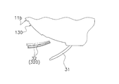
- wing of the air-conditioning indoor unit which concerns on a modification.
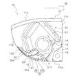
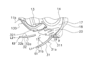
- FIG. 1 is a cross-sectional view of the air conditioning indoor unit 10 when operation is stopped according to an embodiment of the present invention.
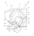
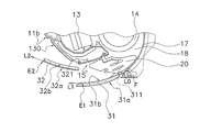
- FIG. 2 is a cross-sectional view of the air conditioning indoor unit 10 during operation. 1 and 2, the air conditioning indoor unit 10 is a wall-hanging type, and a main body casing 11, an indoor heat exchanger 13, an indoor fan 14, a bottom frame 16, and a control unit 40 are mounted thereon.
- the main body casing 11 has a top surface portion 11a, a front panel 11b, a back plate 11c, and a lower horizontal plate 11d, and houses an indoor heat exchanger 13, an indoor fan 14, a bottom frame 16, and a control unit 40 therein. .
- the top surface part 11a is located in the upper part of the main body casing 11, and the inlet (not shown) is provided in the front part of the top surface part 11a.
- the front panel 11b constitutes the front part of the indoor unit, and has a flat shape without a suction port. Further, the upper end of the front panel 11b is rotatably supported by the top surface portion 11a, and can operate in a hinged manner.
- the indoor heat exchanger 13 and the indoor fan 14 are attached to the bottom frame 16.
- the indoor heat exchanger 13 exchanges heat with the passing air.
- the indoor heat exchanger 13 has an inverted V-shape in which both ends are bent downward in a side view, and the indoor fan 14 is located below the indoor heat exchanger 13.
- the indoor fan 14 is a cross-flow fan, blows air taken in from the room against the indoor heat exchanger 13 and then blows it into the room.
- An air outlet 15 is provided at the lower part of the main body casing 11.
- a wind direction adjusting blade 31 that changes the direction of the blown air blown from the blower outlet 15 is rotatably attached to the blower outlet 15.
- the wind direction adjusting blade 31 is driven by a motor (not shown) and can change the direction of the blown air, and can also open and close the blowout port 15.
- the wind direction adjusting blade 31 can take a plurality of postures having different inclination angles.
- a Coanda blade 32 is provided in the vicinity of the air outlet 15.
- the Coanda blade 32 can take a posture inclined in the front-rear direction by a motor (not shown), and is accommodated in the accommodating portion 130 provided in the front panel 11b when the operation is stopped.
- the Coanda blade 32 can take a plurality of postures having different inclination angles. Further, the air outlet 15 is connected to the inside of the main body casing 11 by the air outlet channel 18. The blowout channel 18 is formed along the scroll 17 of the bottom frame 16 from the blowout port 15.
- the indoor air is sucked into the indoor fan 14 through the suction port and the indoor heat exchanger 13 by the operation of the indoor fan 14, and blown out from the blower outlet 15 through the blowout passage 18 from the indoor fan 14.
- the control unit 40 is located on the right side of the indoor heat exchanger 13 and the indoor fan 14 when the main body casing 11 is viewed from the front panel 11b, and controls the rotational speed of the indoor fan 14, the wind direction adjusting blade 31 and the Coanda blade 32. Perform motion control.
- the depth of the depression in this region is set so as to match the thickness dimension of the Coanda blade 32, and constitutes a housing portion 130 in which the Coanda blade 32 is housed.
- the surface of the accommodating part 130 is also a gentle circular curved surface.
- the blower outlet 15 is formed in the lower part of the main body casing 11, and is a rectangular opening which makes a horizontal direction (direction orthogonal to the paper surface of FIG. 1) a long side.
- the lower end of the blower outlet 15 is in contact with the front edge of the lower horizontal plate 11d, and the virtual plane connecting the lower end and the upper end of the blower outlet 15 is inclined forward and upward.
- Scroll 17 The scroll 17 is a partition wall curved so as to face the indoor fan 14 and is a part of the bottom frame 16.
- the end F of the scroll 17 reaches the vicinity of the periphery of the air outlet 15.
- the air passing through the blowout flow path 18 travels along the scroll 17 and is sent in the tangential direction of the end F of the scroll 17. Therefore, if there is no wind direction adjusting blade 31 at the air outlet 15, the air direction of the air blown out from the air outlet 15 is a direction substantially along the tangent L 0 of the terminal end F of the scroll 17.
- the vertical wind direction adjusting plate 20 includes a plurality of blade pieces 201 and a connecting rod 203 that connects the plurality of blade pieces 201. Further, the vertical air direction adjusting plate 20 is disposed nearer the indoor fan 14 than the air direction adjusting blades 31 in the blowout flow path 18. The plurality of blade pieces 201 swing left and right around a state perpendicular to the longitudinal direction as the connecting rod 203 horizontally reciprocates along the longitudinal direction of the outlet 15. The connecting rod 203 is horizontally reciprocated by a motor (not shown). (2-5) Wind direction adjusting blade 31 The wind direction adjusting blade 31 has an area that can block the air outlet 15.
- the outer side surface 31 a is finished to have a gentle circular curved surface that protrudes outwardly as if it is an extension of the curved surface of the front panel 11 b. Further, the inner side surface 31b (see FIG. 2) of the wind direction adjusting blade 31 also forms an arcuate curved surface substantially parallel to the outer surface.
- the wind direction adjusting blade 31 has a rotation shaft 311 at the lower end.
- the rotating shaft 311 is connected to the rotating shaft of a stepping motor (not shown) fixed to the main body casing 11 in the vicinity of the lower end of the air outlet 15.
- the rotation shaft 311 rotates counterclockwise when viewed from the front in FIG. 1, so that the upper end of the airflow direction adjusting blade 31 moves away from the upper end side of the outlet 15 to open the outlet 15.
- the rotation shaft 311 rotates in the clockwise direction in FIG. 1, the upper end of the wind direction adjusting blade 31 operates so as to approach the upper end side of the outlet 15 to close the outlet 15.
- the Coanda blade 32 is stored in the storage unit 130 while the air-conditioning operation is stopped or in an operation in the normal blowing mode described later.
- the Coanda blade 32 moves away from the accommodating portion 130 by rotating.
- the rotation shaft 321 of the Coanda blade 32 is provided in the vicinity of the lower end of the housing portion 130 and inside the main body casing 11 (a position above the upper wall of the outlet flow passage 18).
- the rotating shaft 321 is connected with a predetermined interval. Therefore, as the rotation shaft 321 rotates and the Coanda blade 32 moves away from the housing portion 130 on the front surface of the casing, the height position of the lower end of the Coanda blade 32 rotates so as to become lower.
- the inclination when the Coanda blade 32 rotates and opens is gentler than the inclination of the casing front surface portion.
- the accommodating portion 130 is provided outside the air passage, and the entire Coanda blade 32 is accommodated outside the air passage when being accommodated.
- only a part of the Coanda blade 32 may be accommodated outside the air passage, and the rest may be accommodated in the air passage (for example, the upper wall portion of the air passage).
- the rotating shaft 321 rotates counterclockwise in the front view of FIG. 1, the upper and lower ends of the Coanda blades 32 are separated from the housing portion 130 while drawing an arc.
- the shortest distance between the casing front portion and the accommodating portion 130 is larger than the shortest distance between the lower end and the accommodating portion 130. That is, the Coanda blade 32 is controlled so as to move away from the front surface of the casing as it goes forward.
- the rotation shaft 321 rotates in the clockwise direction in the front view of FIG. 1
- the Coanda blade 32 approaches the storage unit 130 and is finally stored in the storage unit 130.
- the operating state of the Coanda blade 32 includes a state where the Coanda blade 32 is housed in the storage unit 130, a posture rotated and tilted forward and upward, a posture rotated and substantially horizontal, and a posture rotated and tilted forward and downward. is there.
- the outer surface 32a of the Coanda blade 32 is finished to a gentle circular curved surface that protrudes outwardly as if it is an extension of the gentle circular curved surface of the front panel 11b.
- the inner side surface 32 b of the Coanda blade 32 is finished to have an arcuate curved surface that follows the surface of the housing portion 130.
- the dimension in the longitudinal direction of the Coanda blade 32 is set to be equal to or larger than the dimension in the longitudinal direction of the wind direction adjusting blade 31.
- the reason for this is to receive all of the blown air whose wind direction has been adjusted by the wind direction adjusting blade 31 by the Coanda blade 32, and its purpose is to prevent the blown air from the side of the Coanda blade 32 from short-circuiting.
- Direction control of blown air The air-conditioning indoor unit of the present embodiment, as means for controlling the direction of blown air, is a normal blow mode that adjusts the direction of blown air by rotating only the wind direction adjusting blade 31 and the wind direction.
- the adjustment blade 31 and the Coanda blade 32 are rotated so that the Coanda effect uses the Coanda effect to make the blown air flow along the outer surface 32a of the Coanda blade 32, and the tips of the wind direction adjustment blade 31 and the Coanda blade 32, respectively.
- FIG. 3A is a side view of the wind direction adjusting blade 31 and the Coanda blade 32 when the blown air is normally forward blown. In FIG.
- the control unit 40 rotates the wind direction adjusting blade 31 to a position where the inner side surface 31b of the wind direction adjusting blade 31 becomes substantially horizontal.
- wing 31 has comprised the circular arc curved surface like this embodiment, the wind direction adjustment blade
- FIG. 3B is a side view of the wind direction adjusting blade 31 and the Coanda blade 32 when the blown air is normally forward down blown.
- the control unit 40 rotates the wind direction adjusting blade 31 until the tangent at the front end E1 of the inner side surface 31b of the wind direction adjusting blade 31 becomes lower than the horizontal. As a result, the blown air is in a front lower blowing state.
- Coanda (effect) means that if there is a wall near the flow of gas or liquid, it flows in the direction along the wall surface even if the direction of the flow is different from the direction of the wall. It is a phenomenon to try (Asakura Shoten “Dictionary of Law”).
- the Coanda utilization mode includes “Coanda airflow front blowing” and “Coanda airflow ceiling blowing” using this Coanda effect.
- FIG. 4A is a conceptual diagram showing the direction of blown air and the direction of Coanda airflow.
- the inclination of the blown air direction (D1) changed by the wind direction adjusting blade 31 is close to the posture (inclination) of the Coanda blade 32. There is a need. If they are too far apart, the Coanda effect will not occur.
- the Coanda blade 32 and the wind direction adjusting blade 31 need to be equal to or less than a predetermined opening angle, and both the adjustment plates (31, 32) are within the range, and The relationship is established. Thereby, as shown in FIG. 4A, after the wind direction of the blown air is changed to D1 by the wind direction adjusting blade 31, it is further changed to D2 by the Coanda effect.
- FIG. 4B is a conceptual diagram illustrating an example of an opening angle between the wind direction adjusting blade 31 and the Coanda blade 32.
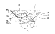
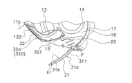
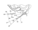
- the wind direction adjusting blade 31 and the Coanda blade 32 have an inner angle formed by the tangent of the end F of the scroll 17 and the Coanda blade 32 and the tangent of the end F of the scroll 17. It is preferable to take a posture that satisfies the condition that it is larger than the inner angle formed by the wind direction adjusting blade 31. 5A (the inner angle R2 formed by the tangent line L0 of the terminal end F of the scroll 17 and the Coanda blade 32 when the Coanda airflow is blown forward and the tangent line L0 of the terminal end F of the scroll 17 and the airflow direction adjusting blade 31 are formed.
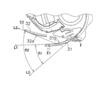
- Comparison diagram with inner angle R1) and FIG. 5B inner angle R2 formed between tangent L0 of end F of scroll 17 and Coanda blade 32 when Coanda airflow ceiling is blown, tangent L0 of end F of scroll 17 and wind direction adjusting blade 31) (Refer to the comparison figure with the internal angle R1).
- 3C is a side view of the wind direction adjusting blade 31 and the Coanda blade 32 during the Coanda airflow forward blow.
- the control unit 40 moves the airflow direction adjustment blade 31 until the tangent L1 at the front end E1 of the inner side surface 31b of the airflow direction adjustment blade 31 becomes lower than the horizontal. Rotate.
- the control unit 40 rotates the Coanda blade 32 until the outer surface 32a of the Coanda blade 32 becomes substantially horizontal.
- the Coanda blade 32 is rotated until the tangent L2 at the front end E2 of the outer surface 32a becomes substantially horizontal. That is, as shown in FIG. 5A, the inner angle R2 formed by the tangent line L0 and the tangent line L2 is larger than the inner angle R1 formed by the tangent line L0 and the tangent line L1.
- the blown air adjusted to the front lower blow by the wind direction adjusting blade 31 becomes a flow attached to the outer surface 32a of the Coanda blade 32 by the Coanda effect, and changes to a Coanda airflow along the outer surface 32a. Therefore, even if the tangential L1 direction at the front end E1 of the airflow direction adjusting blade 31 is the front lower blowing, the tangential L2 direction at the front end E2 of the Coanda blade 32 is horizontal, so that the blown air is blown from the Coanda blade 32 by the Coanda effect. It blows off in the tangent L2 direction at the front end E2 of the outer side surface 32a, that is, in the horizontal direction.
- FIG. 3D is a side view of the wind direction adjusting blade 31 and the Coanda blade 32 when the Coanda airflow ceiling is blown.
- the control unit 40 rotates the airflow direction adjusting blade 31 until the tangent L1 at the front end E1 of the inner side surface 31b of the airflow direction adjusting blade 31 becomes horizontal.
- the control part 40 rotates the Coanda blade
- the blown air adjusted to be blown horizontally by the wind direction adjusting blade 31 becomes a flow attached to the outer surface 32a of the Coanda blade 32 by the Coanda effect, and changes to a Coanda airflow along the outer surface 32a.
- the tangential L2 direction at the front end E2 of the Coanda blade 32 is forward upward blowing, so that the blown air is generated by the Coanda effect by the Coanda effect. It blows out in the tangent L2 direction at the front end E2 of the outer side surface 32a, that is, the ceiling direction. Since the front end portion of the Coanda blade 32 protrudes outward from the air outlet 15, the Coanda airflow reaches further away. Further, since the tip of the Coanda blade 32 is positioned above the outlet 15, the wind is prevented from traveling straightly downward along the scroll 17 on the upper side of the Coanda blade 32. The upward induction of is difficult to be inhibited.
- the Coanda blades 32 are separated from the casing front surface and the inclination becomes gentle, and the blown air becomes more susceptible to the Coanda effect in front of the front panel 11b.
- the blown air whose wind direction is adjusted by the wind direction adjusting blade 31 is forward blowing, it becomes upward air due to the Coanda effect.
- the wind direction is changed while the pressure loss due to the ventilation resistance of the wind direction adjusting blade 31 is suppressed.
- the blown air is guided toward the ceiling while the blower outlet 15 remains open. That is, the blown air is guided toward the ceiling in a state where the ventilation resistance is kept low.
- the size in the longitudinal direction of the Coanda blade 32 is not less than the size in the longitudinal direction of the wind direction adjusting blade 31. Therefore, all of the blown air whose wind direction is adjusted by the wind direction adjusting blade 31 can be received by the Coanda blade 32, and the effect that the blown air is prevented from short-circuiting from the side of the Coanda blade 32 is also achieved.
- FIG. 3E is a side view of the wind direction adjusting blade 31 and the Coanda blade 32 during the down-blowing.
- the control unit 40 rotates the wind direction adjusting blade 31 until the tangent at the front end E1 of the inner side surface 31b of the wind direction adjusting blade 31 is directed downward.
- the control part 40 rotates the Coanda blade
- the blown air passes between the wind direction adjusting blade 31 and the Coanda blade 32 and is blown downward.
- control unit 40 executes the down blowing mode to apply a downward air flow against the outer surface 32 a of the Coanda blade 32. Can be generated.
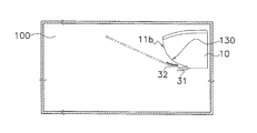
- FIG. 6A is a side view of the air-conditioning indoor unit installation space showing the wind direction of the Coanda airflow when the Coanda blade 32 takes the first posture.
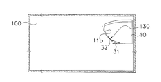
- the air conditioning indoor unit 10 is installed above the indoor side wall.
- the Coanda blade 32 is in a state of being housed in the housing portion 130 (hereinafter referred to as a first posture).
- the air direction adjustment blade 31 is made to face upward from the horizontal so that the blown air whose air direction has been adjusted on the inner surface 31b of the wind direction adjustment blade 31 leaves the inner surface 31b.
- the direction is changed so as to be pulled by the outer surface 32a of the Coanda blade 32, and the first Coanda airflow flows along the outer surface 32a of the Coanda blade 32 and the front panel 11b.
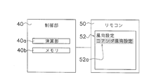
- FIG. 7A is a block diagram showing the relationship between the control unit 40 and the remote controller 50.
- the remote controller 50 transmits an infrared signal wirelessly.
- the remote controller 50 has switching means for switching the wind direction. Specifically, it has a display unit 52 that displays a wind direction selection menu and a cursor 52a for designating each wind direction selection menu so that the user can select the wind direction.
- the user selects “Coanda wind direction setting” from the menu displayed on the display unit 52 with the cursor 52a. Since the technology for selecting and confirming the menu by the remote controller 50 is widely disclosed, detailed description is omitted.
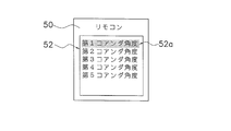
- FIG. 7B is a front view of the display unit 52 showing a lower menu of the “Coanda wind direction setting” menu.
- the first to fifth Coanda angles are prepared in advance in the lower menu of the “Coanda wind direction setting” menu.
- the Coanda blade 32 is displayed.
- the first posture shown in FIG. 6A is taken, and a Coanda airflow in a first direction corresponding to the first Coanda angle is generated.
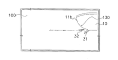
- FIG. 6B is a side view of the air conditioning indoor unit installation space showing the wind direction of the Coanda airflow when the Coanda blade 32 takes the second posture. .
- the second posture of the Coanda blade 32 in FIG. 6B can be achieved by specifying and confirming the second Coanda angle with the cursor 52a in FIG. 7B.
- the Coanda airflow generated when the Coanda blade 32 is in the second posture corresponds to the Coanda airflow described in the section “(3-2-2) Coanda airflow ceiling blowing”.
- the control unit 40 rotates the wind direction adjusting blade 31 until the tangent L1 at the front end E1 of the inner side surface 31b of the wind direction adjusting blade 31 becomes horizontal, Next, the Coanda blade 32 is rotated until the tangent L2 at the front end E2 of the outer side surface 32a is directed upward.
- FIG. 8A is a side view of the wind direction adjusting blade 31 and the Coanda blade 32 when the Coanda blade 32 is in the third posture.
- the third posture of the Coanda blade 32 is downward than the second posture.
- the Coanda blade 32 in the second posture is drawn with a two-dot chain line
- the Coanda blade 32 in the third posture is drawn with a solid line.
- the Coanda airflow is reliably generated in the second posture and the posture of the airflow direction adjusting blade 31 is not changed, the Coanda airflow is directed from the outer surface 32a of the Coanda blade 32 in the third posture that is downward than the second posture. It is clear that it does not peel.
- it can be achieved by selecting the second Coanda angle or the third Coanda angle with the cursor 52a in FIG. 7B.
- the blown air is adjusted by the wind direction adjusting blade 31 in a direction approaching the curved surface 320 of the Coanda blade 32, and the Coanda blade 32 uses the blown air whose air direction is adjusted as its own. Since the air flow is changed to the Coanda airflow along the curved surface 320, the wind direction deflection effect is great.
- the tip of the Coanda blade 32 faces the ceiling, so the Coanda airflow along the curved surface 320 of the Coanda blade 32 is separated from the front panel 11b and You can go upward. In this case, even if there is a suction port above the front surface of the main body casing 11, a short circuit can be prevented.
- the second posture and the third posture of the Coanda blade 32 are selected when it is desired to fly conditioned air far away.
- the Coanda blade 32 is preferably in the second posture.
- the posture of the Coanda blade 32 is preferably the third posture.
- the user can select the posture of the Coanda blade 32 according to the size of the indoor space via the remote controller 50, so that the user can use the conditioned air evenly in the air-conditioning target space. Is possible.
- the outer surface 32a of the Coanda blade 32 may be a convexly curved shape or a planar shape.
- the outer surface 32a is preferably convexly curved in the following points.
- the outer surface 32 a of the Coanda blade 32 is curved in a convex shape to form a curved surface 320. Since the Coanda blade 32 moves away from the front panel 11b as it moves away from the outlet 15, the Coanda airflow along the curved surface 320 of the Coanda blade 32 advances upward while leaving the front panel 11b. be able to. Further, the angle of the tip of the Coanda blade 32 becomes an upward angle, and an upward airflow can be generated without making the inclination angle of the Coanda blade sharp.
- FIG. 6C is a side view of the air-conditioning indoor unit installation space showing the wind direction of the Coanda airflow when the Coanda blade 32 takes the fourth posture.
- 6C can be comprised by specifying and confirming a 4th Coanda angle with the cursor 52a in FIG. 7B.
- the Coanda airflow generated when the Coanda blade 32 is in the fourth posture corresponds to the Coanda airflow described in the section “(3-2-1) Coanda airflow forward blowing”.
- the controller 40 adjusts the wind direction adjusting blade 31 until the tangent line L1 at the front end E1 of the inner side surface 31b of the wind direction adjusting blade 31 becomes lower than the horizontal.
- the Coanda blade 32 is rotated until the outer surface 32a of the Coanda blade 32 becomes substantially horizontal.
- the tangential L1 direction at the front end E1 of the airflow direction adjusting blade 31 is the front lower blowing
- the tangential L2 direction at the front end E2 of the Coanda blade 32 is horizontal, so that the blown air is blown from the Coanda blade 32 by the Coanda effect. It blows off in the tangent L2 direction at the front end E2 of the outer side surface 32a, that is, in the horizontal direction.
- FIG. 8B is a side view of the wind direction adjusting blade 31 and the Coanda blade 32 when the Coanda blade 32 is in the fifth posture.
- the fifth posture of the Coanda blade 32 is more downward than the fourth posture.
- the Coanda blade 32 in the fourth posture is drawn with a two-dot chain line and the Coanda blade 32 in the fifth posture is drawn with a solid line for comparison.
- the Coanda airflow is reliably generated in the fourth posture and the posture of the wind direction adjusting blade 31 is not changed, the Coanda airflow is directed from the outer surface 32a of the Coanda blade 32 in the fifth posture, which is downward than the fourth posture. It is clear that it does not peel.
- it can be achieved by selecting the fourth Coanda angle or the fifth Coanda angle with the cursor 52a in FIG. 7B.
- the attitude of the wind direction adjusting vane 31 is different from each of the first attitude, the second attitude, and the fourth attitude of the Coanda vane 32.
- the Coanda airflow by the Coanda blade 32 can be directed in any direction by a combination of the posture of the wind direction adjusting blade 31 and the posture of the Coanda blade 32.
- a curved surface 320 that is curved in a convex shape is formed on the outer surface 32 a of the Coanda blade 32.
- the Coanda blade 32 moves away from the casing front face as it moves away from the air outlet 15, the Coanda airflow along the curved surface 320 of the Coanda blade 32 advances upward while leaving the casing front face. be able to.
- the angle of the tip of the Coanda blade 32 is an upward angle, and an upward airflow can be generated without making the inclination angle of the Coanda blade 32 abrupt.
- a housing part 130 in which the Coanda blade 32 is housed is formed on the front surface of the casing.
- the Coanda blade 32 is housed in the housing portion 130, and the front surface portion of the casing and the curved surface 320 of the Coanda blade 32 are curved so as to be aligned on one continuous virtual curved surface. Therefore, the appearance of the front portion of the casing when the Coanda blade 32 is accommodated is good, and the deterioration of the design is suppressed.
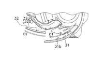
- the curved surface 320 of the Coanda blade 32 is formed of a plurality of curved surfaces 320 having different degrees of curvature.
- the degree of deflection from the direction of the blown air to the direction of the Coanda airflow can be increased while suppressing the Coanda airflow from being separated from the curved surface 320.
- the control unit 40 controls the postures of the wind direction adjusting blade 31 and the Coanda blade 32 when changing the direction of the Coanda airflow.
- the wind direction adjusting blade 31 adjusts the blowing air in a direction approaching the curved surface 320 of the Coanda blade 32, and the Coanda blade 32 changes the blown air whose wind direction is adjusted to the Coanda airflow along its own curved surface 320.
- Great deflection effect (5-7)
- the control unit 40 adjusts the posture of the Coanda blade 32 so that the rear end portion of the Coanda blade 32 faces downward and the front end portion faces upward.
- the curved surface 320 of the Coanda blade 32 is formed as a single curved surface, but may be formed from a plurality of curved surfaces having different degrees of curvature.
- FIG. 9 is a side view of the Coanda blade 32 of the air conditioning indoor unit 10 according to the modification.
- the curved surface 320 of the Coanda blade 32 is formed by three circular arc surfaces having a radius X, a radius Y, and a radius Z.
- the present invention is useful for a wall-mounted air conditioning indoor unit.
Abstract
Description
それゆえ、上記のような導風板がなくともショートサーキットを回避したコアンダ気流を発生させる構成が望まれている。
本願発明の課題は、従来品のような導風板がなくともショートサーキットを回避する方向へ進むコアンダ気流を発生させることができる空調室内機を提供することにある。 This upward Coanda airflow causes a so-called short circuit that is drawn into the suction port along the front surface of the casing. Therefore, in this air conditioner, it is necessary to correct the Coanda airflow obliquely upward by the air guide plate.
Therefore, there is a demand for a configuration that generates a Coanda airflow that avoids a short circuit without the air guide plate as described above.
The subject of this invention is providing the air-conditioning indoor unit which can generate | occur | produce the Coanda airflow which advances to the direction which avoids a short circuit, even if there is no baffle like a conventional product.
この空調室内機では、コアンダ羽根の姿勢は、吹出口から離れるにしたがってケーシング前面部から離れる姿勢となるので、コアンダ羽根の湾曲面に沿ったコアンダ気流は、ケーシング前面部から離れながら、且つ、上向きに進むことができる。その結果、吹出空気の上吹きを実現し、且つ、ケーシング前面部の上方に吸込口があってもショートサーキットを防止することができる。さらに、コアンダ羽根の下面が凸状に湾曲しているので、コアンダ羽根が平板状である場合と比較して、コアンダ羽根先端部の角度が上向きの角度となり、コアンダ羽根の傾斜角度を急にすることなく、上向きの気流を発生させることができる。それゆえ、コアンダ羽根先端部とケーシング前面部との距離を確保することができ、ショートサーキットを回避したコアンダ気流を発生させることができる。 An air conditioning indoor unit according to a first aspect of the present invention is an air conditioning indoor unit having a Coanda effect utilization mode for guiding a flow of blown air blown from a blower outlet in a predetermined direction by a Coanda effect, and Coanda blades, And a control unit. The Coanda blade is provided in the vicinity of the air outlet, and in the Coanda effect utilization mode, the Coanda airflow is changed to a Coanda airflow along the lower surface of itself. The control unit controls the posture of the Coanda blade. In addition, a curved surface that is curved in a convex shape is formed on the lower surface of the Coanda blade. In the Coanda effect utilization mode, the control unit adjusts the Coanda blade to a posture that moves away from the casing front portion as it moves away from the outlet.
In this air conditioner indoor unit, the Coanda blades are positioned away from the front surface of the casing as they move away from the air outlet, so the Coanda airflow along the curved surface of the Coanda blades is separated from the front surface of the casing and upwards. You can proceed to. As a result, it is possible to prevent the short circuit from occurring even if the blow-up air is blown up and a suction port is provided above the front surface of the casing. Furthermore, since the lower surface of the Coanda blade is convexly curved, the angle of the Coanda blade tip is an upward angle compared to the case where the Coanda blade is flat, and the Coanda blade has a sharp inclination angle. An upward airflow can be generated without any problems. Therefore, the distance between the tip of the Coanda blade and the front portion of the casing can be secured, and a Coanda airflow that avoids a short circuit can be generated.
従来の空気調和機は、吹出口の前面で且つ吹出空気の通り道にコアンダ羽根が配置されているので、コアンダ羽根で上向きになったコアンダ気流がケーシング前面部に沿って吸込口に引き込まれないように導風板で斜め上方へ矯正する必要がある。
しかし、この空調室内機では、コアンダ羽根の先端部が上向きになっている。その結果、たとえ、スクロールの終端部の接線が下向きであっても、吹出空気がコアンダ羽根の湾曲面に沿った上向きのコアンダ気流となり、さらに、従来品のような導風板がなくともショートサーキットを回避した気流となる。 The air conditioning indoor unit according to the second aspect of the present invention is the air conditioning indoor unit according to the first aspect, and further includes a scroll. The scroll guides air conditioned to the air outlet. The tangent line at the end of the scroll is downward. In the Coanda effect utilization mode, the control unit adjusts the posture of the Coanda blade so that the tip portion of the Coanda blade faces upward.
In the conventional air conditioner, since the Coanda blades are arranged on the front surface of the blowout port and in the passage of the blown air, the Coanda airflow directed upward by the Coanda blades is not drawn into the suction port along the front surface portion of the casing. It is necessary to correct diagonally upward with a baffle plate.
However, in this air conditioning indoor unit, the tip of the Coanda blade is facing upward. As a result, even if the tangent at the end of the scroll is downward, the blown air becomes an upward Coanda airflow along the curved surface of the Coanda blade, and even if there is no wind guide plate like the conventional product, it is a short circuit The airflow is avoided.
従来の空気調和機は、吹出口の前面で且つ吹出空気の通り道にコアンダ羽根が配置されているので、コアンダ羽根の先端を天井向きにしても、発生したコアンダ気流はショートサーキット防止のため導風板でケーシング前面部から離れる方向へ矯正される必要がある。しかし、この空調室内機では、コアンダ羽根の先端部が天井向きになっているので、コアンダ羽根の湾曲面に沿ったコアンダ気流は、ケーシング前面部から離れながら、且つ、天上向きに進むことができる。その結果、空気の天上吹きを実現し、且つ、ケーシング前面部の上方に吸込口があってもショートサーキットを防止することができる。 An air conditioner indoor unit according to a third aspect of the present invention is the air conditioner indoor unit according to the first aspect, wherein the control unit is configured to control the Coanda blade so that the tip of the Coanda blade faces the ceiling in the Coanda effect utilization mode. Adjust posture.
In the conventional air conditioner, the Coanda blades are arranged in front of the air outlet and in the passage of the blown air. Therefore, even if the tip of the Coanda blade is facing the ceiling, the generated Coanda airflow is guided to prevent short circuit. The plate needs to be corrected in the direction away from the front surface of the casing. However, in this air conditioning indoor unit, since the tip of the Coanda blade is facing the ceiling, the Coanda airflow along the curved surface of the Coanda blade can travel upward and away from the casing front portion. . As a result, air can be blown on the top, and a short circuit can be prevented even if there is a suction port above the front surface of the casing.
この空調室内機では、コアンダ羽根の先端部が吹出口の最下流側の上壁よりも上方に位置しているので、コアンダ羽根の上側において、風が吹出口の最下流側の下壁に沿って斜め下方に直進することが抑制されるため、コアンダ気流の上方への誘導が阻害されにくい。 An air conditioner indoor unit according to a fourth aspect of the present invention is the air conditioner indoor unit according to the third aspect, and when the control unit turns the tip of the Coanda blade toward the ceiling, the tip of the Coanda blade is the outlet. Adjust the posture so that it is located above the top wall.
In this air conditioning indoor unit, the tip of the Coanda blade is positioned above the uppermost wall on the most downstream side of the outlet, so that the wind is along the lowermost wall on the most downstream side of the outlet on the Coanda blade. Therefore, it is difficult to prevent the Coanda airflow from being guided upward.
この空調室内機では、コアンダ羽根収容時のケーシング前面部の見栄えがよく、意匠性の低下が抑制される。 The air conditioning indoor unit according to the fifth aspect of the present invention is the air conditioning indoor unit according to the first aspect, and further includes a normal mode in which the Coanda blades do not generate a Coanda airflow. Moreover, the accommodating part in which a Coanda blade | wing is accommodated is formed in the casing front part. In the normal mode, the Coanda blade is housed in the housing portion, and the casing front surface portion and the curved surface of the Coanda blade are curved so as to be aligned on one continuous virtual curved surface.
In this air conditioning indoor unit, the appearance of the front surface of the casing when the Coanda blades are accommodated is good, and the deterioration of the design is suppressed.
この空調室内機では、吹出空気の方向からコアンダ気流の方向への偏向度合いを高めるために、1つの湾曲面で一気に偏向しようとすると、コアンダ気流が湾曲面から剥離する可能性がある。しかし、複数の湾曲面で偏向度合いを徐々に高めることによって、コアンダ気流が湾曲面から剥離することを抑制しつつ、吹出空気の方向からコアンダ気流の方向への偏向度合いを高めることができる。 The air conditioning indoor unit pertaining to the sixth aspect of the present invention is the air conditioning indoor unit pertaining to the first aspect, wherein the curved surfaces of the Coanda blades are formed of a plurality of curved surfaces with different degrees of curvature.
In this air-conditioning indoor unit, in order to increase the degree of deflection from the direction of the blown air to the direction of the Coanda airflow, if it is attempted to deflect at once with one curved surface, the Coanda airflow may be separated from the curved surface. However, by gradually increasing the degree of deflection at the plurality of curved surfaces, it is possible to increase the degree of deflection from the direction of the blown air to the direction of the Coanda airflow while suppressing separation of the Coanda airflow from the curved surface.
この空調室内機では、風向調整羽根が吹出空気をコアンダ羽根の湾曲面に近づく方向へ風向調整し、コアンダ羽根がその風向調整された吹出空気を自己の湾曲面に沿ったコアンダ気流に変えるので、風向偏向効果が大きい。 An air conditioning indoor unit according to a seventh aspect of the present invention is the air conditioning indoor unit according to the first aspect, and further includes a movable wind direction adjusting blade that changes the vertical direction of the blown air. The control unit controls the attitudes of the wind direction adjusting blade and the Coanda blade when changing the direction of the Coanda airflow.
In this air conditioning indoor unit, the wind direction adjusting blade adjusts the blown air in the direction approaching the curved surface of the Coanda blade, and the Coanda blade changes the blown air whose wind direction is adjusted to the Coanda airflow along its curved surface, Large wind direction deflection effect.
この空調室内機では、コアンダ羽根の後端部が下向きであるので、スクロール自体の角度、つまり下向きの角度に近い角度となり、コアンダ羽根に吹出空気が沿いやすくなる。仮に、後端部が上向きならば、スクロール角度とのギャップが大きくなり、コアンダ羽根に吹出空気が沿わなくなる。
また、コアンダ羽根の先端部が上向きで後端部が下向きであるので、風を捕まえるようにコアンダ羽根の後端部で気流を下面に沿わせておき、段々と上向きに曲げていくことが可能となる。 An air conditioning indoor unit according to an eighth aspect of the present invention is the air conditioning indoor unit according to the first aspect, wherein the control unit has a Coanda blade rear end portion facing downward and a tip portion facing upward in the Coanda effect utilization mode. Adjust the posture of the Coanda blades.
In this air conditioner indoor unit, the rear end portion of the Coanda blade is downward, and therefore the angle of the scroll itself, that is, an angle close to the downward angle, makes it easier for the blown air to follow the Coanda blade. If the rear end portion is upward, the gap with the scroll angle becomes large, and the blown air does not follow the Coanda blade.
In addition, since the tip of the Coanda blade is facing upward and the trailing edge is facing downward, it is possible to keep the airflow along the bottom surface at the rear edge of the Coanda blade so as to catch the wind and bend it upwards gradually. It becomes.
この空調室内機では、コアンダ気流が湾曲面から剥離することを抑制しつつ、吹出空気の方向からコアンダ気流の方向への偏向度合いを高めることができる。 The air conditioning indoor unit according to the ninth aspect of the present invention is the air conditioning indoor unit according to any one of the first to eighth aspects, wherein the radius of the curved surface of the Coanda blade is 50 mm or more and 300 mm or less. .
In this air conditioning indoor unit, the degree of deflection from the direction of the blown air to the direction of the Coanda airflow can be increased while suppressing the Coanda airflow from peeling from the curved surface.
本発明の第2観点に係る空調室内機では、たとえ、スクロールの終端部の接線が下向きであっても、吹出空気がコアンダ羽根の湾曲面に沿った上向きのコアンダ気流となり、さらに、従来品のような導風板がなくともショートサーキットを回避した気流となる。
本発明の第3観点に係る空調室内機では、空気の天上吹きを実現し、且つ、ケーシング前面部の上方に吸込口があってもショートサーキットを防止することができる。
本発明の第4観点に係る空調室内機では、コアンダ羽根の上側において、風が吹出口の最下流側の下壁に沿って斜め下方に直進することが抑制されるため、コアンダ気流の上方への誘導が阻害されにくい。 In the air conditioner indoor unit according to the first aspect of the present invention, it is possible to realize the upward blowing of the blown air and to prevent a short circuit even if there is a suction port above the casing front surface. Furthermore, the distance between the Coanda blade tip and the casing front surface can be secured, and a Coanda airflow that avoids a short circuit can be generated.
In the air conditioning indoor unit according to the second aspect of the present invention, even if the tangent line of the end of the scroll is downward, the blown air becomes an upward Coanda airflow along the curved surface of the Coanda blades. Even without such a wind guide plate, the air flow avoids the short circuit.
In the air conditioning indoor unit according to the third aspect of the present invention, it is possible to prevent the short circuit from occurring even when the air is blown from the top and there is a suction port above the front surface of the casing.
In the air conditioning indoor unit pertaining to the fourth aspect of the present invention, on the upper side of the Coanda blade, since the wind is restrained from going diagonally downward along the lowermost wall on the most downstream side of the blowout port, upward of the Coanda airflow. Induction is difficult to be inhibited.
本発明の第6観点に係る空調室内機では、複数の湾曲面で偏向度合いを徐々に高めることによって、コアンダ気流が湾曲面から剥離することを抑制しつつ、吹出空気の方向からコアンダ気流の方向への偏向度合いを高めることができる。
本発明の第7観点に係る空調室内機では、風向調整羽根が吹出空気をコアンダ羽根の湾曲面に近づく方向へ風向調整し、コアンダ羽根がその風向調整された吹出空気を自己の湾曲面に沿ったコアンダ気流に変えるので、風向偏向効果が大きい。
本発明の第8観点に係る空調室内機では、コアンダ羽根の後端部が下向きであるので、スクロール自体の角度、つまり下向きの角度に近い角度となり、コアンダ羽根に吹出空気が沿いやすくなる。また、風を捕まえるようにコアンダ羽根の後端部で気流を下面に沿わせて、段々と上向きに曲げていくことが可能となる。 In the air conditioning indoor unit pertaining to the fifth aspect of the present invention, the appearance of the casing front surface when the Coanda blades are accommodated is good, and the deterioration of the design is suppressed.
In the air conditioning indoor unit pertaining to the sixth aspect of the present invention, the direction of the Coanda airflow from the direction of the blown air is suppressed while suppressing the separation of the Coanda airflow from the curved surface by gradually increasing the degree of deflection at the plurality of curved surfaces. The degree of deflection can be increased.
In the air conditioning indoor unit according to the seventh aspect of the present invention, the wind direction adjusting blade adjusts the blowing air in a direction approaching the curved surface of the Coanda blade, and the Coanda blade moves the blown air whose wind direction is adjusted along its own curved surface. Since it changes to a Coanda airflow, the wind direction deflection effect is great.
In the air conditioning indoor unit pertaining to the eighth aspect of the present invention, since the rear end of the Coanda blade is downward, the angle of the scroll itself, that is, an angle close to the downward angle, makes it easier for the blown air to follow the Coanda blade. Further, the airflow can be bent along the lower surface at the rear end portion of the Coanda blade so as to catch the wind, and gradually bent upward.
(1)空調室内機10の構成
図1は、本発明の一実施形態に係る運転停止時の空調室内機10の断面図である。また、図2は、運転時の空調室内機10の断面図である。図1及び図2において、空調室内機10は壁掛けタイプであり、本体ケーシング11、室内熱交換器13、室内ファン14、底フレーム16、及び制御部40が搭載されている。
本体ケーシング11は、天面部11a、前面パネル11b、背面板11c及び下部水平板11dを有し、内部に室内熱交換器13、室内ファン14、底フレーム16、及び制御部40を収納している。 Hereinafter, embodiments of the present invention will be described with reference to the drawings. The following embodiments are specific examples of the present invention and do not limit the technical scope of the present invention.
(1) Configuration of Air Conditioning
The
前面パネル11bは室内機の前面部を構成しており、吸込口がないフラットな形状を成している。また、前面パネル11bは、その上端が天面部11aに回動自在に支持され、ヒンジ式に動作することができる。
室内熱交換器13及び室内ファン14は、底フレーム16に取り付けられている。室内熱交換器13は、通過する空気との間で熱交換を行う。また、室内熱交換器13は、側面視において両端が下方に向いて屈曲する逆V字状の形状を成し、その下方に室内ファン14が位置する。室内ファン14は、クロスフローファンであり、室内から取り込んだ空気を、室内熱交換器13に当てて通過させた後、室内に吹き出す。 The
The
The
また、吹出口15の近傍にはコアンダ羽根32が設けられている。コアンダ羽根32は、モータ(図示せず)によって前後方向に傾斜した姿勢をとることが可能であり、運転停止時に前面パネル11bに設けられた収容部130に収容される。コアンダ羽根32は、傾斜角が異なる複数の姿勢をとることが可能である。
また、吹出口15は、吹出流路18によって本体ケーシング11の内部と繋がっている。吹出流路18は、吹出口15から底フレーム16のスクロール17に沿って形成されている。 An
A
Further, the
制御部40は、本体ケーシング11を前面パネル11bから視て室内熱交換器13及び室内ファン14の右側方に位置しており、室内ファン14の回転数制御、風向調整羽根31及びコアンダ羽根32の動作制御を行う。
(2)詳細構成
(2-1)前面パネル11b
図1に示すように、前面パネル11bは本体ケーシング11の上部前方からなだらかな円弧曲面を描きながら下部水平板11dの前方エッジに向かって延びている。前面パネル11bの下部に本体ケーシング11の内側に向かって窪んだ領域がある。この領域の窪み深さはコアンダ羽根32の厚み寸法に合うように設定されており、コアンダ羽根32が収容される収容部130を成している。収容部130の表面もなだらかな円弧曲面である。 The indoor air is sucked into the
The
(2) Detailed configuration (2-1)
As shown in FIG. 1, the
図1に示すように、吹出口15は、本体ケーシング11の下部に形成されており、横方向(図1紙面と直交する方向)を長辺とする長方形の開口である。吹出口15の下端は下部水平板11dの前方エッジに接しており、吹出口15の下端と上端とを結ぶ仮想面は前方上向きに傾斜している。
(2-3)スクロール17
スクロール17は、室内ファン14に対峙するように湾曲した隔壁であり、底フレーム16の一部である。スクロール17の終端Fは、吹出口15の周縁近傍まで到達している。吹出流路18を通る空気は、スクロール17に沿って進み、スクロール17の終端Fの接線方向に送られる。したがって、吹出口15に風向調整羽根31がなければ、吹出口15から吹き出される吹出空気の風向は、スクロール17の終端Fの接線L0に概ね沿った方向である。 (2-2)
As shown in FIG. 1, the
(2-3)
The
垂直風向調整板20は、図1及び図2に示すように、複数の羽根片201と、複数の羽根片201を連結する連結棒203を有している。また、垂直風向調整板20は、吹出流路18において、風向調整羽根31よりも室内ファン14近傍に配置されている。
複数枚の羽根片201は、連結棒203が吹出口15の長手方向に沿って水平往復移動することによって、その長手方向に対して垂直な状態を中心に左右に揺動する。なお、連結棒203は、モータ(図示せず)によって水平往復移動する。
(2-5)風向調整羽根31
風向調整羽根31は、吹出口15を塞ぐことができる程度の面積を有している。風向調整羽根31が吹出口15を閉じた状態において、その外側面31aは前面パネル11bの曲面の延長上にあるような外側に凸のなだらかな円弧曲面に仕上げられている。また、風向調整羽根31の内側面31b(図2参照)も、外面にほぼ平行な円弧曲面を成している。 (2-4) Vertical wind
As shown in FIGS. 1 and 2, the vertical wind
The plurality of
(2-5) Wind
The wind
回動軸311が図1正面視反時計方向に回動することによって、風向調整羽根31の上端が吹出口15の上端側から遠ざかるように動作して吹出口15を開ける。逆に、回動軸311が図1正面視時計方向に回動することによって、風向調整羽根31の上端が吹出口15の上端側へ近づくように動作して吹出口15を閉じる。
風向調整羽根31が吹出口15を開けている状態において、吹出口15から吹き出された吹出空気は、風向調整羽根31の内側面31bに概ね沿って流れる。すなわち、スクロール17の終端Fの接線方向に概ね沿って吹き出された吹出空気は、その風向が風向調整羽根31によってやや上向きに変更される。 The wind
The
In a state where the airflow
コアンダ羽根32は、空調運転が停止している間や後述する通常吹出モードでの運転では収容部130に収納されている。コアンダ羽根32は回動することによって収容部130から離れる。コアンダ羽根32の回動軸321は、収容部130の下端近傍で且つ本体ケーシング11の内側の位置(吹出流路18上壁の上方の位置)に設けられており、コアンダ羽根32の下端部と回動軸321とは所定の間隔を保って連結されている。それゆえ、回動軸321が回動してコアンダ羽根32がケーシング前面部の収容部130から離れるほど、コアンダ羽根32の下端の高さ位置は低くなるように回転する。また、コアンダ羽根32が回転して開いたときの傾斜はケーシング前面部の傾斜よりも緩やかである。
本実施形態では、収容部130は、送風路の外に設けられており、収容時にコアンダ羽根32の全体が送風路の外側に収容される。かかる構造に代えて、コアンダ羽根32の一部のみが送風路の外側に収容され、残りが送風路内(たとえば、送風経路の上壁部)に収容されるようにしてもよい。 (2-6)
The
In the present embodiment, the
コアンダ羽根32が収容部130に収容された状態で、コアンダ羽根32の外側面32aは前面パネル11bのなだらかな円弧曲面の延長上にあるような外側に凸のなだらかな円弧曲面に仕上げられている。また、コアンダ羽根32の内側面32bは、収容部130の表面に沿うような円弧曲面に仕上げられている。 Further, when the
In a state where the
(3)吹出空気の方向制御
本実施形態の空調室内機は、吹出空気の方向を制御する手段として、風向調整羽根31のみを回動させて吹出空気の方向を調整する通常吹出モードと、風向調整羽根31及びコアンダ羽根32を回動させてコアンダ効果によって吹出空気をコアンダ羽根32の外側面32aに沿わせたコアンダ気流にするコアンダ効果利用モードと、風向調整羽根31及びコアンダ羽根32それぞれの先端を前方下向きにして吹出空気を下方に導く下吹きモードを有している。 Further, the dimension in the longitudinal direction of the
(3) Direction control of blown air The air-conditioning indoor unit of the present embodiment, as means for controlling the direction of blown air, is a normal blow mode that adjusts the direction of blown air by rotating only the wind
(3-1)通常吹出モード
通常吹出モードは、風向調整羽根31のみを回動させて吹出空気の方向を調整するモードであり、「通常前吹き」と「通常前方下吹き」とを含む。
(3-1-1)通常前吹き
図3Aは、吹出空気が通常前吹き時の風向調整羽根31及びコアンダ羽根32の側面図である。図3Aにおいて、ユーザーが「通常前吹き」を選択したとき、制御部40は風向調整羽根31の内側面31bが略水平になる位置まで風向調整羽根31を回動させる。なお、本願実施形態のように風向調整羽根31の内側面31bが円弧曲面をなしている場合は、内側面31bの前方端E1における接線が略水平になるまで風向調整羽根31を回動させる。その結果、吹出空気は、前吹き状態となる。 Since the postures of the wind
(3-1) Normal blowout mode The normal blowout mode is a mode in which only the wind
(3-1-1) Normal Front Blow FIG. 3A is a side view of the wind
図3Bは、吹出空気が通常前方下吹き時の風向調整羽根31及びコアンダ羽根32の側面図である。図3Bにおいて、ユーザーは吹出方向を「通常前吹き」よりも下方に向けたいとき、「通常前方下吹き」を選択すればよい。
このとき、制御部40は、風向調整羽根31の内側面31bの前方端E1における接線が水平よりも前下がりになるまで風向調整羽根31を回動させる。その結果、吹出空気は、前方下吹き状態となる。
(3-2)コアンダ効果利用モード
コアンダ(効果)とは、気体や液体の流れのそばに壁があると、流れの方向と壁の方向とが異なっていても、壁面に沿った方向に流れようとする現象である(朝倉書店「法則の辞典」)。コアンダ利用モードは、このコアンダ効果を利用した「コアンダ気流前方吹き」および「コアンダ気流天井吹き」を含む。 (3-1-2) Normal Front Down Blow FIG. 3B is a side view of the wind
At this time, the
(3-2) Coanda effect utilization mode Coanda (effect) means that if there is a wall near the flow of gas or liquid, it flows in the direction along the wall surface even if the direction of the flow is different from the direction of the wall. It is a phenomenon to try (Asakura Shoten "Dictionary of Law"). The Coanda utilization mode includes “Coanda airflow front blowing” and “Coanda airflow ceiling blowing” using this Coanda effect.
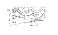
また、風向調整羽根31とコアンダ羽根32との開き角度については、基準位置の取り方次第で定義の方法が異なるので、以下に一例を示す。但し、それに限定されるものではない。図4Bは、風向調整羽根31とコアンダ羽根32との開き角度の一例を表す概念図である。図4Bにおいて、風向調整羽根31の内側面31bの前後端を結ぶ直線と水平線との角度を風向調整羽根31の傾斜角θ1とし、コアンダ羽根32の外側面32aの前後端を結ぶ直線と水平線との角度をコアンダ羽根32の傾斜角θ2としたとき、風向調整羽根31とコアンダ羽根32との開き角度θ=θ2-θ1である。なお、θ1及びθ2は絶対値ではなく、図4B正面視において水平線よりも下方となる場合は負の値である。 Moreover, in the Coanda effect utilization mode of this embodiment, it is preferable that the Coanda blade |
The opening angle between the wind
なお、内角については、図5A(コアンダ気流前方吹き時のスクロール17の終端Fの接線L0とコアンダ羽根32とが成す内角R2と、スクロール17の終端Fの接線L0と風向調整羽根31とが成す内角R1との比較図)、および図5B(コアンダ気流天井吹き時のスクロール17の終端Fの接線L0とコアンダ羽根32とが成す内角R2と、スクロール17の終端Fの接線L0と風向調整羽根31とが成す内角R1との比較図)を参照のこと。 In both “Coanda airflow forward blowing” and “Coanda airflow ceiling blowing”, the wind
5A (the inner angle R2 formed by the tangent line L0 of the terminal end F of the
また、コアンダ羽根32の後端部の高さ位置は運転停止時よりも低くなっているので、上流側でのコアンダ効果によるコアンダ気流が生成し易い。
(3-2-1)コアンダ気流前方吹き
図3Cは、コアンダ気流前方吹き時の風向調整羽根31及びコアンダ羽根32の側面図である。図3Cにおいて、「コアンダ気流前方吹き」が選択されたとき、制御部40は、風向調整羽根31の内側面31bの前方端E1における接線L1が水平よりも前下がりになるまで風向調整羽根31を回動させる。 Further, as shown in FIG. 5B, in the
In addition, since the height position of the rear end portion of the
(3-2-1) Coanda Airflow Forward Blow FIG. 3C is a side view of the wind
風向調整羽根31で前方下吹きに調整された吹出空気は、コアンダ効果によってコアンダ羽根32の外側面32aに付着した流れとなり、この外側面32aに沿ったコアンダ気流に変わる。
したがって、風向調整羽根31の前方端E1における接線L1方向が前方下吹きであっても、コアンダ羽根32の前方端E2における接線L2方向が水平であるので、吹出空気は、コアンダ効果によってコアンダ羽根32の外側面32aの前方端E2における接線L2方向、すなわち水平方向に吹き出される。 Next, the
The blown air adjusted to the front lower blow by the wind
Therefore, even if the tangential L1 direction at the front end E1 of the airflow
(3-2-2)コアンダ気流天井吹き
図3Dは、コアンダ気流天井吹き時の風向調整羽根31及びコアンダ羽根32の側面図である。図3Dにおいて、「コアンダ気流天井吹き」が選択されたとき、制御部40は風向調整羽根31の内側面31bの前方端E1における接線L1が水平になるまで風向調整羽根31を回動させる。 Thus, the
(3-2-2) Coanda Airflow Ceiling Blow FIG. 3D is a side view of the wind
したがって、風向調整羽根31の前方端E1における接線L1方向が前方吹きであっても、コアンダ羽根32の前方端E2における接線L2方向が前方上吹きであるので、吹出空気は、コアンダ効果によってコアンダ羽根32の外側面32aの前方端E2における接線L2方向、すなわち天井方向に吹き出される。コアンダ羽根32の先端部は吹出口15より外側に突出しているので、コアンダ気流はより遠方に到達する。さらに、コアンダ羽根32の先端部は吹出口15よりも上方に位置しているので、コアンダ羽根32の上側において、風がスクロール17に沿って斜め下方に直進することが抑制されるため、コアンダ気流の上方への誘導が阻害されにくい。 Next, the
Therefore, even if the tangential L1 direction at the front end E1 of the wind
その結果、吹出口15が開き気味のまま、吹出空気が天井方向へ誘導される。つまり、通風抵抗が低く保たれた状態で吹出空気が天井方向へ誘導される。
なお、コアンダ羽根32の長手方向の寸法は、風向調整羽根31の長手方向の寸法以上である。それゆえ、風向調整羽根31で風向調節された吹出空気すべてをコアンダ羽根32で受けることができ、コアンダ羽根32の側方から吹出空気がショートサーキットすることが防止されるという効果も奏している。 Thus, the
As a result, the blown air is guided toward the ceiling while the
The size in the longitudinal direction of the
図3Eは、下吹き時の風向調整羽根31及びコアンダ羽根32の側面図である。図3Eにおいて、「下吹き」が選択されたとき、制御部40は風向調整羽根31の内側面31bの前方端E1における接線が下向きなるまで風向調整羽根31を回動させる。
次に、制御部40は、外側面32aの前方端E2における接線が下向きとなるまでコアンダ羽根32を回動させる。その結果、吹出空気は、風向調整羽根31とコアンダ羽根32との間を通過し、下向きに吹き出される。
特に、風向調整羽根31がスクロール17の終端部の接線角度より下向きになったときでも、制御部40が下吹きモードを実行することによって、コアンダ羽根32の外側面32aに当てて下向きの気流を生成することができる。 (3-3) Down-blowing mode FIG. 3E is a side view of the wind
Next, the
In particular, even when the wind
上記のような吹出空気の方向制御を利用した空調室内機の動作について、以下、図面を参照しながら説明する。
(4-1)コアンダ羽根32の第1姿勢
図6Aは、コアンダ羽根32が第1姿勢をとるときのコアンダ気流の風向を示す空調室内機設置空間の側面図である。図6Aにおいて、空調室内機10は室内側壁の上方に設置されている。コアンダ羽根32は、収納部130に収納されている状態(以後、第1姿勢とよぶ)である。コアンダ羽根32が第1姿勢のときに風向調整羽根31の姿勢を水平よりも上向きにすることによって、風向調整羽根31の内側面31bで風向調整された吹出空気がその内側面31bを離れた後、コアンダ羽根32の外側面32aに引っ張られるように方向を変え、第1コアンダ気流となってコアンダ羽根32の外側面32aおよび前面パネル11bに沿うように流れる。 (4) Operation The operation of the air-conditioning indoor unit using the blown air direction control as described above will be described below with reference to the drawings.
(4-1) First posture of
ここで、ユーザーがコアンダ気流を選択する方法について説明する。図7Aは、制御部40とリモコン50との関係を示すブロック図である。図7Aにおいて、リモコン50は赤外線信号を無線で送信する。リモコン50には、風向を切り換えるための切換手段を有している。具体的には、ユーザーが風向を選択できるように、風向選択メニューを表示する表示部52と、各風向選択メニューを指定するためのカーソル52aを有している。
先ず、ユーザーは、表示部52に表示されたメニューの中から「コアンダ風向設定」をカーソル52aで選択する。なお、リモコン50によるメニューの選択および確定するための技術は広く公開されているので詳細な説明は省略する。 This first posture is selected when it is desired to form a short circuit. The purpose is to dehumidify the room without causing a feeling of cold wind as disclosed in a publicly known document (Japanese Patent Laid-Open No. 10-9659).
Here, a method for the user to select the Coanda airflow will be described. FIG. 7A is a block diagram showing the relationship between the
First, the user selects “Coanda wind direction setting” from the menu displayed on the
(4-2)コアンダ羽根32の第2姿勢および第3姿勢
次に、図6Bは、コアンダ羽根32が第2姿勢をとるときのコアンダ気流の風向を示す空調室内機設置空間の側面図である。図6Bにおけるコアンダ羽根32の第2姿勢は、図7Bにおいてカーソル52aで第2コアンダ角度を指定し確定することによって成し得る。コアンダ羽根32が第2姿勢のときに発生するコアンダ気流は、「(3-2-2)コアンダ気流天井吹き」の段で説明したコアンダ気流に相当する。第2コアンダ角度が選択されたとき、図3Dに示すように、制御部40は風向調整羽根31の内側面31bの前方端E1における接線L1が水平になるまで風向調整羽根31を回動させ、次に、外側面32aの前方端E2における接線L2が前方上向きとなるまでコアンダ羽根32を回動させる。したがって、風向調整羽根31の前方端E1における接線L1方向が前方吹きであっても、コアンダ羽根32の前方端E2における接線L2方向が前方上吹きであるので、吹出空気は、コアンダ効果によってコアンダ羽根32の外側面32aの前方端E2における接線L2方向、すなわち天井方向に吹き出される。 FIG. 7B is a front view of the
(4-2) Second posture and third posture of
第2姿勢でコアンダ気流が確実に発生し、且つ、風向調整羽根31の姿勢が変わらないとすれば、第2姿勢よりも下向きである第3姿勢でコアンダ気流がコアンダ羽根32の外側面32aから剥離しないことは明らかである。このように、コアンダ気流天井吹きを実施したいときは、図7Bにおいてカーソル52aで第2コアンダ角度、若しくは第3コアンダ角度を選択することによって成し得る。 Once the Coanda airflow is generated, it is possible to adjust the wind direction of the Coanda airflow by changing only the angle of the
If the Coanda airflow is reliably generated in the second posture and the posture of the airflow
また、第2姿勢および第3姿勢では、コアンダ羽根32の先端部は天井向きになっているので、コアンダ羽根32の湾曲面320に沿ったコアンダ気流は、前面パネル11bから離れながら、且つ、天上向きに進むことができる。この場合は、本体ケーシング11の前面上方に吸込口があってもショートサーキットを防止することができる。
他方、コアンダ羽根32の後端部は下向きであるので、スクロール17自体の角度、つまり下向きの角度に近い角度となり、コアンダ羽根32に吹出空気が沿いやすくなる。なお、仮に後端部が上向きならば、スクロール角度とのギャップが大きくなり、コアンダ羽根に吹出空気が沿わなくなる。 In the second posture and the third posture of the
In the second posture and the third posture, the tip of the
On the other hand, since the rear end portion of the
本実施形態では、コアンダ羽根32の第2姿勢および第3姿勢は、調和空気を遠方に飛ばしたいときに選択されることを想定している。例えば、吹出口15から天井までの高さ距離、および吹出口15からその対面壁までの対面距離がともに大きい場合は、コアンダ羽根32の姿勢は第2姿勢が好ましい。他方、吹出口15から天井までの高さ距離は小さいが、吹出口15からその対面壁までの対面距離が大きい場合などはコアンダ羽根32の姿勢は第3姿勢が好ましい。このようにユーザーは、リモコン50を介して室内空間の大きさに応じてコアンダ羽根32の姿勢を選択することができるので、使い勝手がよい上に、調和空気を空調対象空間に均一に行き渡らせることが可能となる。 Further, since the front end portion of the
In the present embodiment, it is assumed that the second posture and the third posture of the
コアンダ羽根32の形状について、コアンダ羽根32の外側面32aは、凸状に湾曲している形状であっても、平面形状であってもよいが、以下の点で、外側面32aは凸状に湾曲していることが好ましい。
図8Aにおいて、コアンダ羽根32の外側面32aは、凸状に湾曲して湾曲面320を形成している。コアンダ羽根32の姿勢は、吹出口15から離れるにしたがって前面パネル11bから離れる姿勢となるので、コアンダ羽根32の湾曲面320に沿ったコアンダ気流は、前面パネル11bから離れながら、且つ、上向きに進むことができる。また、コアンダ羽根32先端部の角度が上向きの角度となり、コアンダ羽根の傾斜角度を急にすることなく、上向きの気流を発生させることができる。 (4-2-1) About the shape of the
In FIG. 8A, the
また、前面パネル11bとコアンダ羽根32の湾曲面320とは1つの連続的な仮想曲面上に並ぶように湾曲させることによって、コアンダ羽根32収容時のケーシング前面部の見栄えがよくなる。
(4-3)コアンダ羽根32の第4姿勢および第5姿勢
さらに、図6Cは、コアンダ羽根32が第4姿勢をとるときのコアンダ気流の風向を示す空調室内機設置空間の側面図である。図6Cにおけるコアンダ羽根32の第4姿勢は、図7Bにおいてカーソル52aで第4コアンダ角度を指定し確定することによって成し得る。コアンダ羽根32が第4姿勢のときに発生するコアンダ気流は、「(3-2-1)コアンダ気流前方吹き」の段で説明したコアンダ気流に相当する。第4コアンダ角度が選択されたとき、図3Cに示すように、制御部40は、風向調整羽根31の内側面31bの前方端E1における接線L1が水平よりも前下がりになるまで風向調整羽根31を回動させ、次に、コアンダ羽根32の外側面32aが略水平になる位置までコアンダ羽根32を回動させる。したがって、風向調整羽根31の前方端E1における接線L1方向が前方下吹きであっても、コアンダ羽根32の前方端E2における接線L2方向が水平であるので、吹出空気は、コアンダ効果によってコアンダ羽根32の外側面32aの前方端E2における接線L2方向、すなわち水平方向に吹き出される。 Further, even if the tangent line of the end portion of the
Further, the
(4-3) Fourth posture and fifth posture of
第4姿勢でコアンダ気流が確実に発生し、且つ、風向調整羽根31の姿勢が変わらないとすれば、第4姿勢よりも下向きである第5姿勢でコアンダ気流がコアンダ羽根32の外側面32aから剥離しないことは明らかである。このように、コアンダ気流前方吹きを実施したいときは、図7Bにおいてカーソル52aで第4コアンダ角度、若しくは第5コアンダ角度を選択することによって成し得る。 Once the Coanda airflow is generated, it is possible to adjust the wind direction of the Coanda airflow by changing only the angle of the
If the Coanda airflow is reliably generated in the fourth posture and the posture of the wind
(5)特徴
(5-1)
空調室内機10では、コアンダ羽根32の外側面32aには、凸状に湾曲する湾曲面320が形成されている。コアンダ羽根32の姿勢は、吹出口15から離れるにしたがってケーシング前面部から離れる姿勢となるので、コアンダ羽根32の湾曲面320に沿ったコアンダ気流は、ケーシング前面部から離れながら、且つ、上向きに進むことができる。コアンダ羽根32が平板状である場合と比較して、コアンダ羽根32先端部の角度が上向きの角度となり、コアンダ羽根32の傾斜角度を急にすることなく、上向きの気流を発生させることができる。 As apparent from the above description, the attitude of the wind
(5) Features (5-1)
In the air conditioning
空調室内機10では、スクロールの終端部の接線は下向きである。他方、コアンダ羽根32の先端部が上向きになっている。それゆえ、たとえ、スクロール17の終端部の接線が下向きであっても、吹出空気がコアンダ羽根32の湾曲面320に沿った上向きのコアンダ気流となる。
(5-3)
空調室内機10では、制御部40は、コアンダ効果利用モードにおいて、コアンダ羽根32の先端部が天井向きとなるようにコアンダ羽根32の姿勢を調整する。コアンダ羽根の先端部が天井向きになっているので、コアンダ羽根32の湾曲面320に沿ったコアンダ気流は、ケーシング前面部から離れながら、且つ、天上向きに進むことができる。その結果、空気の天上吹きを実現し、且つ、ケーシング前面部の上方に吸込口があってもショートサーキットを防止することができる。 (5-2)
In the air conditioning
(5-3)
In the air conditioning
空調室内機10では、ケーシング前面部には、コアンダ羽根32が収容される収容部130が形成されている。通常モードでは、コアンダ羽根32が収容部130に収容され、ケーシング前面部とコアンダ羽根32の湾曲面320とは1つの連続的な仮想曲面上に並ぶように湾曲している。それゆえ、コアンダ羽根32収容時のケーシング前面部の見栄えがよく、意匠性の低下が抑制される。
(5-5)
空調室内機10では、コアンダ羽根32の湾曲面320が、湾曲度合いの異なる複数の湾曲面320で形成されている。複数の湾曲面320で偏向度合いを徐々に高めることによって、コアンダ気流が湾曲面320から剥離することを抑制しつつ、吹出空気の方向からコアンダ気流の方向への偏向度合いを高めることができる。 (5-4)
In the air conditioning
(5-5)
In the air conditioning
空調室内機10では、制御部40は、コアンダ気流の向きを変更するとき風向調整羽根31およびコアンダ羽根32の姿勢を制御する。風向調整羽根31は吹出空気をコアンダ羽根32の湾曲面320に近づく方向へ風向調整し、コアンダ羽根32がその風向調整された吹出空気を自己の湾曲面320に沿ったコアンダ気流に変えるので、風向偏向効果が大きい。
(5-7)
空調室内機10では、制御部40が、コアンダ効果利用モードにおいて、コアンダ羽根32の後端部が下向き、先端部が上向きとなるようにコアンダ羽根32の姿勢を調整する。コアンダ羽根32の後端部が下向きであるので、スクロール自体の角度、つまり下向きの角度に近い角度となり、コアンダ羽根32に吹出空気が沿いやすくなる。なお、仮に後端部が上向きならば、スクロール角度とのギャップが大きくなり、コアンダ羽根32に吹出空気が沿わなくなる。 (5-6)
In the air conditioning
(5-7)
In the air conditioning
(5-8)
空調室内機10では、コアンダ羽根32の湾曲面320の半径が、50mm以上、300mm以下である。その結果、コアンダ気流が湾曲面320から剥離することを抑制しつつ、吹出空気の方向からコアンダ気流の方向への偏向度合いを高めることができる。
(6)変形例
上記実施形態では、コアンダ羽根32の湾曲面320は単一曲面で形成されているが、湾曲度合いの異なる複数の湾曲面で形成されてもよい。 Further, since the front end portion of the
(5-8)
In the air conditioning
(6) Modification In the above embodiment, the
15 吹出口
17 スクロール
31 風向調整羽根
32 コアンダ羽根
32a 外側面(下面)
40 制御部
130 収容部
320 湾曲面 DESCRIPTION OF
40
Claims (9)
- 吹出口(15)から吹き出される吹出空気の流れをコアンダ効果により所定の方向へ誘導するコアンダ効果利用モードを有する空調室内機であって、
前記吹出口(15)の近傍に設けられ、前記コアンダ効果利用モードにおいて前記吹出空気を自己の下面(32a)に沿わせたコアンダ気流にするコアンダ羽根(32)と、
前記コアンダ羽根(32)の姿勢を制御する制御部(40)と、
を備え、
前記コアンダ羽根(32)の前記下面(32a)には、凸状に湾曲する湾曲面(320)が形成されており、
前記制御部(40)は、前記コアンダ効果利用モードにおいて、前記コアンダ羽根(32)を前記吹出口(15)から離れるにしたがってケーシング前面部から離れる姿勢へ調整する、
空調室内機(10)。 An air conditioning indoor unit having a Coanda effect use mode for guiding the flow of blown air blown from the blowout port (15) in a predetermined direction by the Coanda effect,
A Coanda blade (32) provided in the vicinity of the air outlet (15), and in the Coanda effect utilization mode, the Coanda blade (32) for making the air blown along the self lower surface (32a).
A control unit (40) for controlling the posture of the Coanda blade (32);
With
The lower surface (32a) of the Coanda blade (32) is formed with a curved surface (320) that curves in a convex shape.
The control unit (40) adjusts the Coanda blade (32) to a posture away from the casing front surface as the Coanda blade (32) moves away from the outlet (15) in the Coanda effect utilization mode.
Air conditioning indoor unit (10). - 空気調和された空気を前記吹出口(15)まで導くスクロール(17)をさらに備え、
前記スクロール(17)の終端部の接線は下向きであり、
前記制御部(40)は、前記コアンダ効果利用モードにおいて、前記コアンダ羽根(32)の先端部が上向きとなるように前記コアンダ羽根(32)の姿勢を調整する、
請求項1に記載の空調室内機(10)。 A scroll (17) for guiding air-conditioned air to the outlet (15);
The tangent at the end of the scroll (17) is downward,
The control unit (40) adjusts the attitude of the Coanda blade (32) so that the tip of the Coanda blade (32) faces upward in the Coanda effect utilization mode.
The air conditioning indoor unit (10) according to claim 1. - 前記制御部(40)は、前記コアンダ効果利用モードにおいて、前記コアンダ羽根(32)の先端部が天井向きとなるように前記コアンダ羽根(32)の姿勢を調整する、
請求項1に記載の空調室内機(10)。 The control unit (40) adjusts the posture of the Coanda blade (32) so that a tip portion of the Coanda blade (32) faces the ceiling in the Coanda effect utilization mode.
The air conditioning indoor unit (10) according to claim 1. - 前記制御部(40)は、前記コアンダ羽根(32)の先端部を天井向きにする際に、前記コアンダ羽根(32)の先端部が前記吹出口(15)の上壁よりも上に位置するように姿勢を調整する、
請求項3に記載の空調室内機(10)。 The control unit (40) has the tip of the Coanda blade (32) positioned above the upper wall of the outlet (15) when the tip of the Coanda blade (32) faces the ceiling. Adjust the posture so that
The air conditioning indoor unit (10) according to claim 3. - 前記コアンダ羽根(32)が前記コアンダ気流を発生させない通常モードをさらに有する請求項1に記載の空調室内機であって、
前記ケーシング前面部に前記コアンダ羽根(32)が収容される収容部(130)が形成されており、
前記通常モードでは、前記コアンダ羽根(32)が前記収容部(130)に収容され、前記ケーシング前面部と前記コアンダ羽根(32)の前記湾曲面(320)とは1つの連続的な仮想曲面上に並ぶように湾曲している、
空調室内機(10)。 The air conditioning indoor unit according to claim 1, further comprising a normal mode in which the Coanda blades (32) do not generate the Coanda airflow.
A housing part (130) in which the Coanda blade (32) is housed is formed in the casing front surface part,
In the normal mode, the Coanda blade (32) is housed in the housing portion (130), and the casing front surface portion and the curved surface (320) of the Coanda blade (32) are on one continuous virtual curved surface. Curved to line up,
Air conditioning indoor unit (10). - 前記コアンダ羽根(32)の前記湾曲面(320)は、湾曲度合いの異なる複数の湾曲面で形成されている、
請求項1に記載の空調室内機(10)。 The curved surface (320) of the Coanda blade (32) is formed of a plurality of curved surfaces having different degrees of curvature.
The air conditioning indoor unit (10) according to claim 1. - 前記吹出空気の上下方向を変更する可動の風向調整羽根(31)をさらに備え、
前記制御部(40)は、前記コアンダ気流の向きを変更するとき前記風向調整羽根(31)及び前記コアンダ羽根(32)の姿勢を制御する、
請求項1に記載の空調室内機(10)。 A movable wind direction adjusting blade (31) for changing the vertical direction of the blown air;
The control unit (40) controls the attitude of the wind direction adjusting blade (31) and the Coanda blade (32) when changing the direction of the Coanda airflow.
The air conditioning indoor unit (10) according to claim 1. - 前記制御部(40)は、前記コアンダ効果利用モードにおいて、前記コアンダ羽根(32)の後端部が下向き、先端部が上向きとなるように前記コアンダ羽根(32)の姿勢を調整する、
請求項1に記載の空調室内機(10)。 The controller (40) adjusts the posture of the Coanda blade (32) in the Coanda effect utilization mode so that the rear end portion of the Coanda blade (32) faces downward and the tip portion faces upward.
The air conditioning indoor unit (10) according to claim 1. - 前記コアンダ羽根(32)の湾曲面(320)の半径は、50mm以上、300mm以下である、
請求項1から請求項8に記載の空調室内機(10)。 The radius of the curved surface (320) of the Coanda blade (32) is not less than 50 mm and not more than 300 mm.
The air conditioning indoor unit (10) according to claim 1 to 8.
Priority Applications (9)
| Application Number | Priority Date | Filing Date | Title |
|---|---|---|---|
| CN201280053268.0A CN103906981B (en) | 2011-10-31 | 2012-10-02 | Air-conditioning indoor unit |
| BR112014010240A BR112014010240A2 (en) | 2011-10-31 | 2012-10-02 | indoor air conditioning unit |
| KR1020147014189A KR101429427B1 (en) | 2011-10-31 | 2012-10-02 | Air-conditioning indoor unit |
| SG11201401920XA SG11201401920XA (en) | 2011-10-31 | 2012-10-02 | Air-conditioning indoor unit |
| EP12846065.6A EP2778551B1 (en) | 2011-10-31 | 2012-10-02 | Air-conditioning indoor unit |
| ES12846065.6T ES2653587T3 (en) | 2011-10-31 | 2012-10-02 | Indoor air conditioning unit |
| IN1027KON2014 IN2014KN01027A (en) | 2011-10-31 | 2012-10-02 | |
| AU2012333903A AU2012333903C1 (en) | 2011-10-31 | 2012-10-02 | Air-conditioning indoor unit |
| US14/354,896 US9488381B2 (en) | 2011-10-31 | 2012-10-02 | Air-conditioning indoor unit |
Applications Claiming Priority (2)
| Application Number | Priority Date | Filing Date | Title |
|---|---|---|---|
| JP2011239778A JP5408227B2 (en) | 2011-10-31 | 2011-10-31 | Air conditioning indoor unit |
| JP2011-239778 | 2011-10-31 |
Publications (1)
| Publication Number | Publication Date |
|---|---|
| WO2013065438A1 true WO2013065438A1 (en) | 2013-05-10 |
Family
ID=48191796
Family Applications (1)
| Application Number | Title | Priority Date | Filing Date |
|---|---|---|---|
| PCT/JP2012/075462 WO2013065438A1 (en) | 2011-10-31 | 2012-10-02 | Air-conditioning indoor unit |
Country Status (12)
| Country | Link |
|---|---|
| US (1) | US9488381B2 (en) |
| EP (1) | EP2778551B1 (en) |
| JP (1) | JP5408227B2 (en) |
| KR (1) | KR101429427B1 (en) |
| CN (1) | CN103906981B (en) |
| AU (1) | AU2012333903C1 (en) |
| BR (1) | BR112014010240A2 (en) |
| ES (1) | ES2653587T3 (en) |
| IN (1) | IN2014KN01027A (en) |
| MY (1) | MY169353A (en) |
| SG (1) | SG11201401920XA (en) |
| WO (1) | WO2013065438A1 (en) |
Cited By (2)
| Publication number | Priority date | Publication date | Assignee | Title |
|---|---|---|---|---|
| CN107300210A (en) * | 2016-04-01 | 2017-10-27 | 珠海格力电器股份有限公司 | Indoor apparatus of air conditioner |
| JP7082293B2 (en) | 2019-09-17 | 2022-06-08 | ダイキン工業株式会社 | Air conditioning indoor unit and air conditioner |
Families Citing this family (21)
| Publication number | Priority date | Publication date | Assignee | Title |
|---|---|---|---|---|
| JP5365675B2 (en) * | 2011-09-30 | 2013-12-11 | ダイキン工業株式会社 | Air conditioning indoor unit |
| JP5403125B2 (en) * | 2011-10-31 | 2014-01-29 | ダイキン工業株式会社 | Air conditioning indoor unit |
| WO2015058546A1 (en) | 2013-10-25 | 2015-04-30 | 优视科技有限公司 | Webpage preloading method and device |
| CN104329786B (en) * | 2014-09-18 | 2018-04-27 | 青岛海尔空调器有限总公司 | The head cover of air treatment system |
| WO2016133261A1 (en) * | 2015-02-18 | 2016-08-25 | 삼성전자주식회사 | Air conditioner |
| CN106152436B (en) * | 2015-04-17 | 2019-04-12 | 青岛海尔空调电子有限公司 | A kind of cassette air-conditioning and its air ducting |
| JP2017040408A (en) * | 2015-08-18 | 2017-02-23 | ジョンソンコントロールズ ヒタチ エア コンディショニング テクノロジー(ホンコン)リミテッド | Air conditioner |
| JP2018084368A (en) * | 2016-11-24 | 2018-05-31 | 株式会社富士通ゼネラル | Indoor equipment of air conditioner |
| CN106907829A (en) * | 2017-02-28 | 2017-06-30 | 广东美的制冷设备有限公司 | A kind of indoor set heat-production control method, control device and air-conditioning |
| FR3065791A1 (en) * | 2017-05-01 | 2018-11-02 | Eric Convoi Nelson | AIR DEFLECTOR, RECYCLING, FOR WALL TYPE AIR CONDITIONERS AND CEILING LIGHTS (INDOOR UNITS). |
| CN111295554B (en) * | 2017-09-06 | 2021-10-29 | Lg电子株式会社 | Ceiling type indoor unit of air conditioner |
| WO2019050307A1 (en) * | 2017-09-06 | 2019-03-14 | 엘지전자 주식회사 | Ceiling-type indoor unit of air conditioner |
| WO2019050309A1 (en) * | 2017-09-06 | 2019-03-14 | 엘지전자 주식회사 | Ceiling-type indoor unit of air conditioner |
| WO2019050308A1 (en) * | 2017-09-06 | 2019-03-14 | 엘지전자 주식회사 | Ceiling-type indoor unit of air conditioner |
| CN111373208B (en) * | 2017-09-20 | 2022-04-01 | Lg电子株式会社 | Ceiling type indoor unit of air conditioner |
| JP6515968B2 (en) * | 2017-09-27 | 2019-05-22 | ダイキン工業株式会社 | Air conditioning indoor unit |
| KR102508191B1 (en) | 2017-11-10 | 2023-03-09 | 삼성전자주식회사 | Air conditioner |
| JP7025672B2 (en) * | 2019-09-17 | 2022-02-25 | ダイキン工業株式会社 | Air conditioner indoor unit |
| CN114391080A (en) | 2019-09-17 | 2022-04-22 | 大金工业株式会社 | Indoor unit of air conditioner |
| JP6849032B2 (en) * | 2019-09-17 | 2021-03-24 | ダイキン工業株式会社 | Air conditioning indoor unit and air conditioner |
| JP6897735B2 (en) * | 2019-09-17 | 2021-07-07 | ダイキン工業株式会社 | Air conditioning indoor unit and air conditioner |
Citations (7)
| Publication number | Priority date | Publication date | Assignee | Title |
|---|---|---|---|---|
| JPH109659A (en) | 1996-06-26 | 1998-01-16 | Toshiba Corp | Air conditioner |
| JP2003232531A (en) | 2002-02-06 | 2003-08-22 | Sharp Corp | Air conditioner |
| JP2004361011A (en) * | 2003-06-05 | 2004-12-24 | Hitachi Home & Life Solutions Inc | Air conditioner |
| JP2007051866A (en) * | 2006-09-11 | 2007-03-01 | Sharp Corp | Air conditioner |
| JP2009097755A (en) * | 2007-10-15 | 2009-05-07 | Mitsubishi Electric Corp | Air conditioner |
| JP2011214727A (en) * | 2010-03-31 | 2011-10-27 | Hitachi Appliances Inc | Air conditioner |
| JP2012197970A (en) * | 2011-03-22 | 2012-10-18 | Panasonic Corp | Air conditioner |
Family Cites Families (17)
| Publication number | Priority date | Publication date | Assignee | Title |
|---|---|---|---|---|
| US4350472A (en) * | 1978-11-14 | 1982-09-21 | Sanyo Electric Co., Ltd. | Electric fan apparatus |
| AU583505B2 (en) * | 1984-05-10 | 1989-05-04 | Matsushita Electric Industrial Co., Ltd. | Flow deflecting assembly |
| JP2993412B2 (en) * | 1995-11-20 | 1999-12-20 | 三菱電機株式会社 | Air outlet and air conditioner provided with the air outlet |
| US5762034A (en) * | 1996-01-16 | 1998-06-09 | Board Of Trustees Operating Michigan State University | Cooling fan shroud |
| JP3302906B2 (en) * | 1997-07-15 | 2002-07-15 | 三菱電機株式会社 | Air conditioner |
| JP3669322B2 (en) * | 2000-11-21 | 2005-07-06 | ダイキン工業株式会社 | Air conditioner indoor unit |
| JP4017483B2 (en) * | 2002-09-25 | 2007-12-05 | シャープ株式会社 | Air conditioner |
| JP3686963B2 (en) * | 2003-11-28 | 2005-08-24 | シャープ株式会社 | Air conditioner |
| JP2005188847A (en) * | 2003-12-26 | 2005-07-14 | Fujitsu General Ltd | Air conditioner |
| JP4991365B2 (en) | 2007-03-29 | 2012-08-01 | カヤバ工業株式会社 | Dimension measuring apparatus and dimension measuring method |
| DE602008002586D1 (en) * | 2008-07-31 | 2010-10-28 | Fiat Ricerche | Motor vehicle dashboard with main center and outlet openings for the ventilation air |
| US20110010958A1 (en) * | 2009-07-16 | 2011-01-20 | Wayne Clark | Quiet hair dryer |
| CN102207327A (en) * | 2010-03-31 | 2011-10-05 | 日立空调·家用电器株式会社 | Air conditioner |
| US20120168117A1 (en) * | 2011-01-04 | 2012-07-05 | Automotive Components Holdings, Llc | Automotive HVAC Diffuser With Cooperating Wall Guide And Vane |
| JP5120482B1 (en) * | 2011-07-01 | 2013-01-16 | ダイキン工業株式会社 | Air conditioning indoor unit |
| DE102012008264A1 (en) * | 2012-04-25 | 2013-10-31 | Airbus Operations Gmbh | Passenger service system with improved airflow |
| JP6015902B2 (en) * | 2012-05-09 | 2016-10-26 | スズキ株式会社 | Vehicle ventilation structure |
-
2011
- 2011-10-31 JP JP2011239778A patent/JP5408227B2/en active Active
-
2012
- 2012-10-02 IN IN1027KON2014 patent/IN2014KN01027A/en unknown
- 2012-10-02 EP EP12846065.6A patent/EP2778551B1/en active Active
- 2012-10-02 SG SG11201401920XA patent/SG11201401920XA/en unknown
- 2012-10-02 BR BR112014010240A patent/BR112014010240A2/en not_active Application Discontinuation
- 2012-10-02 US US14/354,896 patent/US9488381B2/en active Active
- 2012-10-02 AU AU2012333903A patent/AU2012333903C1/en active Active
- 2012-10-02 ES ES12846065.6T patent/ES2653587T3/en active Active
- 2012-10-02 MY MYPI2014700856A patent/MY169353A/en unknown
- 2012-10-02 CN CN201280053268.0A patent/CN103906981B/en active Active
- 2012-10-02 KR KR1020147014189A patent/KR101429427B1/en not_active IP Right Cessation
- 2012-10-02 WO PCT/JP2012/075462 patent/WO2013065438A1/en active Application Filing
Patent Citations (7)
| Publication number | Priority date | Publication date | Assignee | Title |
|---|---|---|---|---|
| JPH109659A (en) | 1996-06-26 | 1998-01-16 | Toshiba Corp | Air conditioner |
| JP2003232531A (en) | 2002-02-06 | 2003-08-22 | Sharp Corp | Air conditioner |
| JP2004361011A (en) * | 2003-06-05 | 2004-12-24 | Hitachi Home & Life Solutions Inc | Air conditioner |
| JP2007051866A (en) * | 2006-09-11 | 2007-03-01 | Sharp Corp | Air conditioner |
| JP2009097755A (en) * | 2007-10-15 | 2009-05-07 | Mitsubishi Electric Corp | Air conditioner |
| JP2011214727A (en) * | 2010-03-31 | 2011-10-27 | Hitachi Appliances Inc | Air conditioner |
| JP2012197970A (en) * | 2011-03-22 | 2012-10-18 | Panasonic Corp | Air conditioner |
Non-Patent Citations (3)
| Title |
|---|
| "Press Release Room Air Conditioner X Series o Hatsubai", 6 September 2011 (2011-09-06), XP055135824, Retrieved from the Internet <URL:http://panasonic.co.jp/corp/news/official. data/data.dir/jn110906-1/jn110906-1.html> * |
| PANASONIC CORP.: "AIR CONDITIONER TOKUSEN PAMPHLET S X SERIES", 1 October 2011 (2011-10-01), pages 5, 6, 10, 11, XP008172374 * |
| PANASONIC CORP.: "TORIATSUKAI SETSUMEISHO", 21 October 2011 (2011-10-21), pages 1, 6 - 8, 12, 13, 32 TO 37, 52, XP055135825, Retrieved from the Internet <URL:http://dl-ctlg. panasonic.jp/manual/cs/cs_12x_22_56_02.pdf> * |
Cited By (3)
| Publication number | Priority date | Publication date | Assignee | Title |
|---|---|---|---|---|
| CN107300210A (en) * | 2016-04-01 | 2017-10-27 | 珠海格力电器股份有限公司 | Indoor apparatus of air conditioner |
| CN107300210B (en) * | 2016-04-01 | 2020-10-02 | 珠海格力电器股份有限公司 | Indoor unit of air conditioner |
| JP7082293B2 (en) | 2019-09-17 | 2022-06-08 | ダイキン工業株式会社 | Air conditioning indoor unit and air conditioner |
Also Published As
| Publication number | Publication date |
|---|---|
| JP2013096637A (en) | 2013-05-20 |
| ES2653587T3 (en) | 2018-02-07 |
| KR20140079511A (en) | 2014-06-26 |
| AU2012333903A1 (en) | 2014-06-05 |
| CN103906981B (en) | 2015-04-08 |
| AU2012333903B2 (en) | 2015-09-10 |
| AU2012333903C1 (en) | 2015-12-24 |
| EP2778551A4 (en) | 2015-01-07 |
| US9488381B2 (en) | 2016-11-08 |
| KR101429427B1 (en) | 2014-08-12 |
| SG11201401920XA (en) | 2014-10-30 |
| EP2778551A1 (en) | 2014-09-17 |
| CN103906981A (en) | 2014-07-02 |
| US20140308888A1 (en) | 2014-10-16 |
| EP2778551B1 (en) | 2017-07-26 |
| MY169353A (en) | 2019-03-25 |
| BR112014010240A2 (en) | 2017-04-18 |
| IN2014KN01027A (en) | 2015-10-09 |
| JP5408227B2 (en) | 2014-02-05 |
Similar Documents
| Publication | Publication Date | Title |
|---|---|---|
| JP5408227B2 (en) | Air conditioning indoor unit | |
| JP5408228B2 (en) | Air conditioning indoor unit | |
| JP5365675B2 (en) | Air conditioning indoor unit | |
| WO2013065436A1 (en) | Air-conditioning indoor unit | |
| JP5403125B2 (en) | Air conditioning indoor unit | |
| JP5536158B2 (en) | Air conditioning indoor unit | |
| JP5403046B2 (en) | Air conditioning indoor unit | |
| WO2013099914A1 (en) | Air-conditioning indoor unit | |
| JP5408318B1 (en) | Air conditioning indoor unit | |
| JP5834911B2 (en) | Air conditioning indoor unit | |
| JP5408319B1 (en) | Air conditioning indoor unit | |
| JP5413535B2 (en) | Air conditioning indoor unit | |
| JP5772589B2 (en) | Air conditioning indoor unit | |
| JP5783041B2 (en) | Air conditioning indoor unit |
Legal Events
| Date | Code | Title | Description |
|---|---|---|---|
| 121 | Ep: the epo has been informed by wipo that ep was designated in this application |
Ref document number: 12846065 Country of ref document: EP Kind code of ref document: A1 |
|
| WWE | Wipo information: entry into national phase |
Ref document number: 14354896 Country of ref document: US |
|
| NENP | Non-entry into the national phase |
Ref country code: DE |
|
| REEP | Request for entry into the european phase |
Ref document number: 2012846065 Country of ref document: EP |
|
| WWE | Wipo information: entry into national phase |
Ref document number: 2012846065 Country of ref document: EP |
|
| ENP | Entry into the national phase |
Ref document number: 20147014189 Country of ref document: KR Kind code of ref document: A |
|
| ENP | Entry into the national phase |
Ref document number: 2012333903 Country of ref document: AU Date of ref document: 20121002 Kind code of ref document: A |
|
| REG | Reference to national code |
Ref country code: BR Ref legal event code: B01A Ref document number: 112014010240 Country of ref document: BR |
|
| ENP | Entry into the national phase |
Ref document number: 112014010240 Country of ref document: BR Kind code of ref document: A2 Effective date: 20140429 |