WO2013058389A1 - 非空気入りタイヤ - Google Patents
非空気入りタイヤ Download PDFInfo
- Publication number
- WO2013058389A1 WO2013058389A1 PCT/JP2012/077166 JP2012077166W WO2013058389A1 WO 2013058389 A1 WO2013058389 A1 WO 2013058389A1 JP 2012077166 W JP2012077166 W JP 2012077166W WO 2013058389 A1 WO2013058389 A1 WO 2013058389A1
- Authority
- WO
- WIPO (PCT)
- Prior art keywords
- tire
- elastic connecting
- connecting plate
- ring member
- width direction
- Prior art date
Links
Images


Classifications
-
- B—PERFORMING OPERATIONS; TRANSPORTING
- B60—VEHICLES IN GENERAL
- B60C—VEHICLE TYRES; TYRE INFLATION; TYRE CHANGING; CONNECTING VALVES TO INFLATABLE ELASTIC BODIES IN GENERAL; DEVICES OR ARRANGEMENTS RELATED TO TYRES
- B60C7/00—Non-inflatable or solid tyres
- B60C7/10—Non-inflatable or solid tyres characterised by means for increasing resiliency
- B60C7/14—Non-inflatable or solid tyres characterised by means for increasing resiliency using springs
-
- B—PERFORMING OPERATIONS; TRANSPORTING
- B60—VEHICLES IN GENERAL
- B60B—VEHICLE WHEELS; CASTORS; AXLES FOR WHEELS OR CASTORS; INCREASING WHEEL ADHESION
- B60B9/00—Wheels of high resiliency, e.g. with conical interacting pressure-surfaces
- B60B9/02—Wheels of high resiliency, e.g. with conical interacting pressure-surfaces using springs resiliently mounted bicycle rims
- B60B9/04—Wheels of high resiliency, e.g. with conical interacting pressure-surfaces using springs resiliently mounted bicycle rims in leaf form
-
- B—PERFORMING OPERATIONS; TRANSPORTING
- B60—VEHICLES IN GENERAL
- B60C—VEHICLE TYRES; TYRE INFLATION; TYRE CHANGING; CONNECTING VALVES TO INFLATABLE ELASTIC BODIES IN GENERAL; DEVICES OR ARRANGEMENTS RELATED TO TYRES
- B60C7/00—Non-inflatable or solid tyres
- B60C7/10—Non-inflatable or solid tyres characterised by means for increasing resiliency
- B60C7/14—Non-inflatable or solid tyres characterised by means for increasing resiliency using springs
- B60C7/146—Non-inflatable or solid tyres characterised by means for increasing resiliency using springs extending substantially radially, e.g. like spokes
-
- B—PERFORMING OPERATIONS; TRANSPORTING
- B60—VEHICLES IN GENERAL
- B60C—VEHICLE TYRES; TYRE INFLATION; TYRE CHANGING; CONNECTING VALVES TO INFLATABLE ELASTIC BODIES IN GENERAL; DEVICES OR ARRANGEMENTS RELATED TO TYRES
- B60C7/00—Non-inflatable or solid tyres
- B60C7/22—Non-inflatable or solid tyres having inlays other than for increasing resiliency, e.g. for armouring
Definitions
- the present invention relates to a non-pneumatic tire that does not need to be filled with pressurized air when in use.
- This application claims priority based on Japanese Patent Application No. 2011-230680 for which it applied to Japan on October 20, 2011, and uses the content here.
- the present invention has been made in consideration of such circumstances, and an object of the present invention is to provide a non-pneumatic tire that can be easily assembled and can also reduce the weight.
- a non-pneumatic tire in order to solve the above-described problems and achieve such an object, includes an attachment body attached to an axle, an inner cylinder body that is externally attached to the attachment body, and A ring member including an outer cylinder surrounding the inner cylinder from the outer side in the tire radial direction.
- a plurality of non-pneumatic tires are disposed along the tire circumferential direction between the inner cylindrical body and the outer cylindrical body, and a connecting member that relatively elastically displaces both the cylindrical bodies.
- the ring member and the plurality of connecting members are integrally formed.
- a non-pneumatic tire that can be easily assembled and has a reduced weight can be obtained.
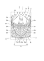
- FIG. 1 it is the schematic perspective view which decomposed
- the non-pneumatic tire 1 includes an attachment body 11 that is attached to an axle (not shown), an inner cylinder body 12 that is externally attached to the attachment body 11, and an outer cylinder body 13 that surrounds the inner cylinder body 12 from the outside in the tire radial direction.
- a ring member 14 provided.
- a plurality of non-pneumatic tires 1 are disposed between the inner cylinder 12 and the outer cylinder 13 along the tire circumferential direction, and the cylinders 12 and 13 can be relatively elastically displaced.
- a tread member 16 disposed on the outer peripheral surface side of the outer cylindrical body 13 over the entire circumference thereof.
- the attachment body 11, the inner cylinder body 12, the outer cylinder body 13, and the tread member 16 are each arranged coaxially with the common shaft.
- this common axis is referred to as an axis O
- a direction along the axis O is referred to as a tire width direction H
- a direction orthogonal to the axis O is referred to as a tire radial direction
- a direction around the axis O is referred to as a tire circumferential direction.
- the attachment body 11, the inner cylinder body 12, the outer cylinder body 13, and the tread member 16 are disposed such that the center portions in the tire width direction H are aligned with each other.
- the outer cylinder 13 of the ring member 14 is larger in the tire width direction H (that is, the width) than the inner cylinder 12.
- a plurality of protrusions 12a that protrude toward the inner side in the tire radial direction and extend over the entire length in the tire width direction H are disposed on the inner peripheral surface of the inner cylindrical body 12 at intervals in the tire circumferential direction. ing.
- the mounting body 11 includes a mounting cylinder portion 17 to which the front end portion of the axle is mounted, an outer ring portion 18 that surrounds the mounting cylinder portion 17 from the outside in the tire radial direction, and a mounting body 11 And a plurality of ribs 19 that connect the cylindrical portion 17 and the outer ring portion 18.
- the mounting cylinder part 17, the outer ring part 18, and the rib 19 are integrally formed of a metal material such as an aluminum alloy.
- the mounting cylinder portion 17 and the outer ring portion 18 are formed in a cylindrical shape and are arranged coaxially with the axis O.
- the plurality of ribs 19 are arranged point-symmetrically with respect to the axis O.
- a plurality of key groove portions 18a that are recessed toward the inside in the tire radial direction and that extend in the tire width direction H are formed on the outer peripheral surface of the outer ring portion 18 at intervals in the tire circumferential direction.
- the key groove portion 18a opens only on one side of both ends in the tire width direction H on the outer peripheral surface of the outer ring portion 18, and the other side is closed.
- the protrusions 12a of the inner cylindrical body 12 of the ring member 14 are fitted into these key groove portions 18a.
- the pair of side wall surfaces and the bottom wall surface facing each other in the tire circumferential direction form a right angle.
- a pair of side wall surfaces rising from the inner peripheral surface of the inner cylindrical body 12 and a top wall surface facing the inner side in the tire radial direction out of the outer surface of the protruding portion 12a form a right angle.
- the sizes in the tire circumferential direction of the ridge portion 12a and the key groove portion 18a are equal to each other.
- a concave portion 18b that is recessed toward the other side in the tire width direction H and into which the plate material 28 is fitted is formed at the edge corresponding to the key groove portion 18a at one edge of the outer ring portion 18 in the tire width direction H. Yes.
- a through hole is formed in the plate material 28.
- a female screw portion communicating with the through hole of the plate member 28 fitted in the concave portion 18b is formed on the wall surface facing the one side in the tire width direction H among the wall surfaces forming the concave portion 18b. Note that a plurality of these female screw portions and through holes are formed at intervals in the tire circumferential direction.
- a plurality of lightening holes penetrating in the tire radial direction are arranged at intervals in the tire width direction H at portions located between the key groove portions 18 a adjacent in the tire circumferential direction.
- a plurality of hole rows 18c are formed at intervals in the tire circumferential direction.
- the rib 19 is also formed with a lightening hole 19a penetrating in the tire width direction H.
- the tread member 16 is formed in a cylindrical shape and integrally covers the outer peripheral surface side of the outer cylinder portion 13 of the ring member 14 over the entire area.
- the tread member 16 is made of, for example, vulcanized rubber obtained by vulcanizing natural rubber and / or a rubber composition, or a thermoplastic material.
- the thermoplastic material include a thermoplastic elastomer or a thermoplastic resin.
- thermoplastic elastomer examples include an amide-based thermoplastic elastomer (TPA), an ester-based thermoplastic elastomer (TPC), an olefin-based thermoplastic elastomer (TPO), a styrene-based thermoplastic elastomer (TPS), and urethane as defined in JIS K6418.
- TPA amide-based thermoplastic elastomer
- TPC ester-based thermoplastic elastomer
- TPO olefin-based thermoplastic elastomer
- TPS styrene-based thermoplastic elastomer
- urethane examples include urethane resin, olefin resin, vinyl chloride resin, and polyamide resin. From the viewpoint of wear resistance, it is preferable to form the tread member 16 from vulcanized rubber.
- the connecting member 15 includes a first elastic connecting plate 21 and a second elastic connecting plate 22 that connect the inner cylinder 12 and the outer cylinder 13 in the ring member 14 to each other.
- the connecting member 15 includes a plurality of first elastic connecting plates 21 arranged along the tire circumferential direction at a position in one tire width direction H, and the second elastic connecting plates 22 in the one tire width direction H.
- a plurality (60 in the illustrated example) are provided along the tire circumferential direction so that a plurality of the tires are arranged along the tire circumferential direction at different positions in the tire width direction H different from the positions. That is, the plurality of first elastic connecting plates 21 are arranged at the same position in the tire width direction H along the tire circumferential direction.
- a plurality of second elastic connecting plates 22 are arranged along the tire circumferential direction at the same position in the tire width direction H away from the first elastic connecting plate 21 in the tire width direction H.
- the plurality of connecting members 15 are separately disposed between the inner cylinder 12 and the outer cylinder 13 in the ring member 14 at positions that are point-symmetric with respect to the axis O. Further, all the connecting members 15 have the same shape and size. Furthermore, the width of the connecting member 15 is smaller than the width of the outer cylinder 13.
- the first elastic connecting plates 21 adjacent to each other in the tire circumferential direction are arranged in non-contact with each other.
- the second elastic connecting plates 22 adjacent in the tire circumferential direction are also arranged in a non-contact manner.
- the first elastic connecting plate 21 and the second elastic connecting plate 22 which are adjacent in the tire width direction H are also arranged in a non-contact manner.
- the widths of the first elastic connecting plate 21 and the second elastic connecting plate 22 are equal to each other.
- the thicknesses of the first elastic connecting plate 21 and the second elastic connecting plate 22 are also equivalent to each other.
- one end 21 a connected to the outer cylinder 13 is located on one side in the tire circumferential direction with respect to the other end 21 b connected to the inner cylinder 12. Further, in the second elastic connecting plate 22, one end 22 a connected to the outer cylinder 13 is positioned on the other side in the tire circumferential direction with respect to the other end 22 b connected to the inner cylinder 12.
- the one end portions 21 a and 22 a of the first elastic connecting plate 21 and the second elastic connecting plate 22 in one connecting member 15 are different from each other in the position in the tire width direction H on the inner peripheral surface of the outer cylindrical body 13. It is connected to the same position in the tire circumferential direction.
- each of the first elastic connecting plate 21 and the second elastic connecting plate 22 intermediate portions 21c and 22c located between the one end portions 21a and 22a and the other end portions 21b and 22b are arranged in the tire circumferential direction.
- a plurality of curved portions 21d to 21f and 22d to 22f that are curved in the tire width direction are formed along the direction in which the connecting plates 21 and 22 extend in a tire side view when the tire 1 is viewed from the tire width direction H.
- the bending directions of the bending portions 21d to 21f and 22d to 22f adjacent to each other in the extending direction among the plurality of bending portions 21d to 21f and 22d to 22f are opposite to each other. It is.
- the plurality of curved portions 21d to 21f formed on the first elastic connecting plate 21 have a first curved portion 21d that is curved so as to protrude toward the other side in the tire circumferential direction. Further, the plurality of bending portions 21d to 21f are located between the first bending portion 21d and the one end portion 21a, and are curved so as to protrude toward one side in the tire circumferential direction, There is a third curved portion 21f that is located between the first curved portion 21d and the other end portion 21b and curved so as to protrude toward one side in the tire circumferential direction.
- the plurality of curved portions 22d to 22f formed on the second elastic connecting plate 22 have first curved portions 22d that are curved so as to protrude toward one side in the tire circumferential direction.
- the plurality of bending portions 22d to 22f are located between the first bending portion 22d and the one end portion 22a, and are bent so as to protrude toward the other side in the tire circumferential direction,
- the first bending portions 21d and 22d have a larger radius of curvature in the tire side view than the second bending portions 21e and 22e and the third bending portions 21f and 22f.
- the first curved portions 21d and 22d are disposed at the center in the extending direction of the first elastic connecting plate 21 and the second elastic connecting plate 22.
- both elastic connecting plates 21 and 22 are equal to each other, and the other end portions 21 b and 22 b of both elastic connecting plates 21 and 22 are in the tire side view,
- the same angle (for example, 20 ° or more and 135 ° or less) on one side and the other side in the tire circumferential direction around the axis O from the position facing the one end portions 21a, 22a in the tire radial direction on the outer peripheral surface of the inner cylinder 12 It is connected to each position separated by one.
- the first bending portions 21d and 22d, the second bending portions 21e and 22e, and the third bending portions 21f and 22f of the first elastic connecting plate 21 and the second elastic connecting plate 22 are mutually connected to the tire.
- the direction of protrusion in the circumferential direction is opposite and the size is the same.
- each connecting member 15 in the side view of the tire extends along the tire radial direction and passes through one end portions 21 a and 22 a of both connecting plates 21 and 22. Is line symmetric.
- the thickness of the one end side portion extending from the central portion in the extending direction to the one end portions 21a and 22a is larger than that of the other end side portion extending from the central portion to the other end portions 21b and 22b. Is also big. Thereby, while suppressing the increase in the weight of the connecting member 15 and ensuring the flexibility of the connecting member 15, the strength of the one end side portion where a large load is easily applied to the first and second elastic connecting plates 21 and 22 is increased. Can be increased. In addition, the one end side part and the other end side part are smoothly connected without a step.
- the ring member 14 and the plurality of connecting members 15 are integrally formed.
- the ring member 14 includes a one-side split ring member 23 located on one side in the tire width direction H and a second-side split ring member 24 located on the other side in the tire width direction H. It is divided. In the illustrated example, the ring member 14 is divided at the center in the tire width direction H.
- the one side split ring member 23 is formed integrally with the first elastic connecting plate 21, and the other side split ring member 24 is formed integrally with the second elastic connecting plate 22. Further, the one-side split ring member 23 and the first elastic connecting plate 21 are integrally formed by casting or injection molding. The other side split ring member 24 and the second elastic connecting plate 22 are integrally formed by casting or injection molding.
- a structure in which the one-side split ring member 23 and the first elastic connecting plate 21 are integrally formed is referred to as a first split case body 31, and the other-side split ring member 24 and the second elastic connecting plate 22 are integrally formed. This is referred to as a second divided case body 32.
- the injection molding may be a general method in which the entire first and second divided case bodies 31 and 32 are simultaneously molded separately.
- the injection molding in each of the first and second divided case bodies 31 and 32, one of the one-side and other-side divided ring members 23 and 24 and the first and second elastic connecting plates 21 and 22 is used as an insert product. It is also possible to use insert molding in which the other is injection molded. Alternatively, the injection molding may be so-called two-color molding or the like.
- the one side and the other side split ring members 23 and 24 and the first and second elastic connecting plates 21 and 22 are formed of different materials. Alternatively, the same material may be used.
- this material examples include a metal material and a resin material, but a resin material, particularly a thermoplastic resin is preferable from the viewpoint of weight reduction.
- a plurality of protrusions 12a formed on the inner cylindrical body 12 may be used as the gate portion.
- the central portion of the cylindrical body 12 in the tire width direction H coincides with each other.
- the width of the inner cylinder 12 is smaller than the width of the outer cylinder 13 and is equal to the width of the first elastic connecting plate 21 and the width of the second elastic connecting plate 22.
- the ends in the tire width direction H of the outer cylindrical body 13 of the one-side divided ring member 23 and the outer cylindrical body 13 of the other-side divided ring member 24 are connected by, for example, welding, fusion, or adhesion.
- welding you may employ
- the edges in the tire width direction H of the inner cylinder 12 of the one-side split ring member 23 and the inner cylinder 12 of the other-side split ring member 24 are separated in the tire width direction H. Thereby, it is prevented that a burr
- first divided case body 31 and the second divided case body 32 have the same shape and the same size as shown in FIG. 3 in a state before the connection between the 31 and 32 as described above.
- the positions of the first divided case body 31 and the second divided case body 32 in the tire circumferential direction are set so that each connecting member 15 is line-symmetrical as described above in the tire side view.
- the end edges in direction H are butted together and connected. Thereby, the non-pneumatic tire 1 is obtained.
- an integrally molded curved portion (that is, the inner cylinder)
- the non-pneumatic tire 1 having high rigidity can be obtained with respect to stress concentrated on the body 12, the outer cylindrical body 13, the first divided case body 31, and the curved portions of the second divided case body 32).
- the non-pneumatic tire 1 includes first and second divided case bodies 31 and 32. Thereby, for example, weight can be suppressed compared with the case where both ends 21a, 22a, 21b, and 22b of connecting member 15, and inner cylinder 12 and outer cylinder 13 are connected using a fastening member etc.
- a plurality of first elastic connecting plates 21 are arranged along the tire circumferential direction at a position in one tire width direction H, and the second elastic connecting plates 22 are arranged around the tire circumference at other tire width direction H positions. A plurality are arranged along the direction. Therefore, it is possible to prevent the connecting members 15 adjacent in the tire circumferential direction from interfering with each other, and it is possible to suppress the number of the arrangement members from being limited.
- one end 21 a connected to the outer cylinder 13 is located on one side in the tire circumferential direction with respect to the other end 21 b connected to the inner cylinder 12.
- one end 22 a connected to the outer cylinder 13 is located on the other side in the tire circumferential direction with respect to the other end 22 b connected to the inner cylinder 12.
- the first elastic connection plate 21 and the second elastic connection plate 22 are In the tire side view, only one of a plurality extending in a certain direction is provided, and the other extending in the other direction is not provided. For this reason, when forming the ring member 14 and the connecting member 15, first, the first and second divided case bodies 31, 32 that have a simple structure and can be easily formed are formed separately. Thereby, the non-pneumatic tire 1 can be formed easily and reliably as compared with the case where the entire ring member 14 and the connecting member 15 are integrally formed to form a case body having a complicated structure.
- segmentation case bodies 31 and 32 are each integrally formed by casting or injection molding. For this reason, the non-pneumatic tire 1 can be formed more easily.
- the divided case bodies 31 and 32 only one of the elastic connecting plates 21 and 22 is disposed between the outer cylinder body 13 and the inner cylinder body 12.
- the divided case bodies 31 and 32 are integrally formed by casting or injection molding, it becomes possible to easily make the molten metal or molten resin easily reach every corner of the mold. It is also possible to suppress the complexity of the structure. Therefore, the non-pneumatic tire 1 can be formed more easily and reliably.
- the connecting member 15 is formed symmetrically with respect to the virtual line L in the tire side view. For this reason, it becomes possible to suppress a difference between the spring constant along one side of the tire circumferential direction in the non-pneumatic tire 1 and the spring constant along the other side, and good maneuverability can be provided. .
- the bending direction of the bending portions 21d to 21f in the first elastic connecting plate 21 and the bending direction of the bending portions 22d to 22f in the second elastic connecting plate 22 are not limited to the above embodiment, and may be changed as appropriate.
- the structure provided with the 1st elastic connection board 21 and the 2nd elastic connection board 22 each as the connection member 15 was shown, it replaced with this and the 1st connection member 15 is 1st.
- a configuration may be adopted in which a plurality of elastic connecting plates 21 and a plurality of second elastic connecting plates 22 are provided in different positions in the tire width direction H.
- a plurality of connecting members 15 may be provided along the tire width direction H between the inner cylinder 12 and the outer cylinder 13.
- each of the other end portions 21b and 22b of the first elastic connecting plate 21 and the second elastic connecting plate 22 is, for example, sandwiching the axis O in the tire radial direction on the outer peripheral surface of the inner cylindrical body 12 instead of the embodiment. May be connected to each position opposite to each other, or on the outer peripheral surface of the inner cylindrical body 12, tires are connected to the respective one end portions 21a, 22a of the first elastic connecting plate 21 and the second elastic connecting plate 22. You may connect with the position etc. which oppose in radial direction. Further, instead of the above-described embodiment, the one end portions 21a and 22a of both the connecting plates 21 and 22 may be connected to the inner peripheral surface of the outer cylindrical body 13 at different positions in the tire circumferential direction.
- first and second divided case bodies 31 and 32 are not limited to the above embodiment, and may be formed by, for example, cutting.
- the non-pneumatic tire 1 shown in FIGS. 1 to 4 was adopted as an example, and the non-pneumatic tire described in the above-mentioned prior art document was adopted as a comparative example.
- the tires were the same size.
- the time and weight required for assembly were measured. As a result, it was confirmed that the time required for assembly was 1/100 in the example compared to the comparative example, and the weight was reduced by 25% in the example compared to the comparative example.
- a non-pneumatic tire that can be easily assembled and has a reduced weight can be obtained.
Landscapes
- Engineering & Computer Science (AREA)
- Mechanical Engineering (AREA)
- Tires In General (AREA)
- Moulds For Moulding Plastics Or The Like (AREA)
- Tyre Moulding (AREA)
Abstract
Description
このような問題を解決するために、例えば下記特許文献1に示されるような、車軸に取り付けられる取り付け体と、前記取り付け体をタイヤ径方向の外側から囲むリング状体と、これらの取り付け体とリング状体との間にタイヤ周方向に沿って複数配設された連結部材と、を備える非空気入りタイヤが提案されている。
非空気入りタイヤ1は、車軸(図示せず)に取り付けられる取り付け体11と、取り付け体11に外装される内筒体12および内筒体12をタイヤ径方向の外側から囲む外筒体13を備えるリング部材14と、を備えている。また、非空気入りタイヤ1は、内筒体12と外筒体13との間にタイヤ周方向に沿って複数配設されるとともに、これら両筒体12、13同士を相対的に弾性変位自在に連結する連結部材15と、外筒体13の外周面側にその全周にわたって配設されたトレッド部材16と、を備えている。
装着筒部17、外リング部18、およびリブ19は、例えばアルミニウム合金等の金属材料で一体に形成されている。装着筒部17および外リング部18は、円筒状に形成され、軸線Oと同軸に配設されている。複数のリブ19は、軸線Oを基準とする点対称に配置されている。
なお、キー溝部18aを形成する壁面のうち、タイヤ周方向で互いに対向する一対の側壁面と底壁面とは直角をなしている。また、突条部12aの外表面のうち、内筒体12の内周面から立ち上がる一対の側壁面と、タイヤ径方向の内側を向く頂壁面と、は直角をなしている。突条部12aおよびキー溝部18aのタイヤ周方向の大きさは、互いに同等である。
なお、外リング部18において、タイヤ周方向で隣り合うキー溝部18a同士の間に位置する部分には、タイヤ径方向に貫通する肉抜き孔がタイヤ幅方向Hに間隔をあけて複数配置されてなる孔列18cが、タイヤ周方向に間隔をあけて複数形成されている。また、リブ19にも、タイヤ幅方向Hに貫通する肉抜き孔19aが形成されている。
連結部材15は、第1弾性連結板21が一のタイヤ幅方向Hの位置にタイヤ周方向に沿って複数配置されるように、かつ第2弾性連結板22が前記一のタイヤ幅方向Hの位置とは異なる他のタイヤ幅方向Hの位置にタイヤ周方向に沿って複数配置されるように、タイヤ周方向に沿って複数(図示の例では60個)設けられている。
すなわち、複数の第1弾性連結板21は、タイヤ幅方向Hにおける同一の位置にタイヤ周方向に沿って複数配置されている。また、複数の第2弾性連結板22は、第1弾性連結板21からタイヤ幅方向Hに離れた同一のタイヤ幅方向Hの位置にタイヤ周方向に沿って複数配置されている。
タイヤ周方向で隣り合う第1弾性連結板21同士は、互いに非接触に配置されている。タイヤ周方向で隣り合う第2弾性連結板22同士も、互いに非接触に配置されている。さらに、タイヤ幅方向Hで隣り合う第1弾性連結板21および第2弾性連結板22同士も、互いに非接触に配置されている。
第1弾性連結板21および第2弾性連結板22のそれぞれの幅は、互いに同等である。また、第1弾性連結板21および第2弾性連結板22のそれぞれの厚さも、互いに同等である。
1つの連結部材15における第1弾性連結板21および第2弾性連結板22の各一端部21a、22aは、外筒体13の内周面において、タイヤ幅方向Hの位置を互いに異ならせて、タイヤ周方向における同一の位置に連結されている。
第2弾性連結板22に形成された複数の湾曲部22d~22fは、タイヤ周方向の一方側に向けて突となるように湾曲した第1湾曲部22dを有している。また、複数の湾曲部22d~22fは、第1湾曲部22dと一端部22aとの間に位置しかつタイヤ周方向の他方側に向けて突となるように湾曲した第2湾曲部22eと、第1湾曲部22dと他端部22bとの間に位置しかつタイヤ周方向の他方側に向けて突となるように湾曲した第3湾曲部22fと、を有している。
図示の例では、第1湾曲部21d、22dは、第2湾曲部21e、22eおよび第3湾曲部21f、22fよりも、前記タイヤ側面視の曲率半径が大きい。なお、第1湾曲部21d、22dは、第1弾性連結板21および第2弾性連結板22の延びる方向における中央部に配置されている。
また、両弾性連結板21、22それぞれにおいて、前述した延びる方向の中央部から一端部21a、22aにわたる一端側部分の厚さは、前記中央部から他端部21b、22bにわたる他端側部分よりも大きい。これにより、連結部材15の重量の増大を抑えたり、連結部材15の柔軟性を確保したりしながら、第1、第2弾性連結板21、22において大きな負荷がかかり易い一端側部分の強度を高めることができる。なお、これら一端側部分と他端側部分とは、段差なく滑らかに連なっている。
図1に示されるように、リング部材14は、タイヤ幅方向Hの一方側に位置する一方側分割リング部材23と、タイヤ幅方向Hの他方側に位置する他方側分割リング部材24と、に分割されている。図示の例では、リング部材14はタイヤ幅方向Hの中央部で分割されている。
さらに、一方側分割リング部材23および第1弾性連結板21は、鋳造若しくは射出成形により一体に形成されている。また、他方側分割リング部材24および第2弾性連結板22は、鋳造若しくは射出成形により一体に形成されている。
以下、一方側分割リング部材23および第1弾性連結板21が一体に形成されたものを第1分割ケース体31といい、他方側分割リング部材24および第2弾性連結板22が一体に形成されたものを第2分割ケース体32という。
また、第1、第2分割ケース体31、32それぞれにおいて、一方側、他方側分割リング部材23、24と、第1、第2弾性連結板21、22と、は、互いに異なる材質で形成してもよいし、同一の材質で形成してもよい。なお、この材質としては、金属材料や樹脂材料等が挙げられるが、軽量化の観点から樹脂材料、特に熱可塑性樹脂が好ましい。
なお、第1、第2分割ケース体31、32それぞれの全体を各別に同時に射出成形する場合には、内筒体12に形成された複数の突条部12aをゲート部分としてもよい。
また、一方側分割リング部材23の内筒体12、および他方側分割リング部材24の内筒体12それぞれのタイヤ幅方向Hの端縁同士は、タイヤ幅方向Hに離れている。これにより、取り付け体11に外嵌される内筒体12の内周面にバリが生じることが防止されている。
前述のように連結するに際し、各連結部材15が前記タイヤ側面視で前述のように線対称となるように、第1分割ケース体31および第2分割ケース体32それぞれのタイヤ周方向の位置を合わせつつ、これらの両分割ケース体31、32のタイヤ幅方向Hの向きを互いに逆向きにした状態で、第1分割ケース体31および第2分割ケース体32の各外筒体13のタイヤ幅方向Hの端縁同士を突き合わせて連結する。これにより、非空気入りタイヤ1が得られる。
また、複数の連結部材15それぞれの両端部21a、22a、21b、22bを、内筒体12および外筒体13にそれぞれ連結した場合と比較して、一体成形された湾曲部(すなわち、内筒体12、外筒体13、第1分割ケース体31、及び第2分割ケース体32の湾曲部)に集中する応力に対して、高い剛性を有する非空気入りタイヤ1を得ることができる。
さらに、第1弾性連結板21が、一のタイヤ幅方向Hの位置にタイヤ周方向に沿って複数配置されるとともに、第2弾性連結板22が、他のタイヤ幅方向Hの位置にタイヤ周方向に沿って複数配置されている。したがって、タイヤ周方向で隣り合う連結部材15同士が干渉し合うことを抑えることが可能になり、その配設個数に制限が生じることを抑制することができる。
しかも、前述のように、各分割ケース体31、32において、外筒体13と内筒体12との間には、両弾性連結板21、22のうちの一方だけが配設されている。これにより、各分割ケース体31、32を鋳造若しくは射出成形により一体に形成するに際し、溶湯や溶融樹脂を、型の内部の隅々にまで確実に到達させ易くすることが可能になり、型の構造が複雑になることを抑えることも可能になる。したがって、非空気入りタイヤ1をより一層容易かつ確実に形成することができる。
また、前記実施形態では、連結部材15として第1弾性連結板21および第2弾性連結板22をそれぞれ1つずつ備えた構成を示したが、これに代えて、1つの連結部材15に第1弾性連結板21および第2弾性連結板22がそれぞれ複数ずつ、互いのタイヤ幅方向Hの位置を異ならせて備えられた構成を採用してもよい。
また、連結部材15を、内筒体12と外筒体13との間にタイヤ幅方向Hに沿って複数設けてもよい。
また、前記実施形態に代えて、両連結板21、22の各一端部21a、22aを、外筒体13の内周面にタイヤ周方向位置を互いに異ならせて連結してもよい。
また、リング部材14をタイヤ幅方向Hに3個以上分割してもよいし、分割しなくてもよい。
さらに、第1、第2分割ケース体31、32は、前記実施形態に限らず例えば、切削加工等で形成してもよい。
実施例として、図1から図4で示した非空気入りタイヤ1を採用し、また比較例として、前述の先行技術文献に記載された非空気入りタイヤを採用した。なお、両タイヤのサイズは同じものとした。
両タイヤのそれぞれについて、組み立てに要した時間、および重量を測定した。
その結果、組み立てに要した時間が、実施例では比較例と比べて100分の1となり、重量が、実施例では比較例と比べて25%軽減できたことが確認された。
11 取り付け体
12 内筒体
13 外筒体
14 リング部材
15 連結部材
21 第1弾性連結板
22 第2弾性連結板
21a、22a 一端部
21b、22b 他端部
23 一方側分割リング部材
24 他方側分割リング部材
H タイヤ幅方向
L 仮想線
O 軸線
Claims (5)
- 車軸に取り付けられる取り付け体と、
前記取り付け体に外装される内筒体、および前記内筒体をタイヤ径方向の外側から囲む外筒体を備えるリング部材と、
前記内筒体と前記外筒体との間にタイヤ周方向に沿って複数配設されるとともに、これらの両筒体同士を相対的に弾性変位自在に連結する連結部材と、を備え、
前記リング部材および複数の前記連結部材は一体に形成されている非空気入りタイヤ。 - 前記連結部材は、前記両筒体同士を連結する第1弾性連結板および第2弾性連結板を備え、
前記第1弾性連結板のうち、前記外筒体に連結された一端部は、前記内筒体に連結された他端部よりもタイヤ周方向の一方側に位置し、
前記第2弾性連結板のうち、前記外筒体に連結された一端部は、前記内筒体に連結された他端部よりもタイヤ周方向の他方側に位置し、
前記第1弾性連結板は、一のタイヤ幅方向位置にタイヤ周方向に沿って複数配置されるとともに、前記第2弾性連結板は、前記一のタイヤ幅方向位置とは異なる他のタイヤ幅方向位置にタイヤ周方向に沿って複数配置されている請求項1に記載の非空気入りタイヤ。 - 前記リング部材は、タイヤ幅方向の一方側に位置する一方側分割リング部材と、タイヤ幅方向の他方側に位置する他方側分割リング部材と、に分割され、
前記一方側分割リング部材は、前記第1弾性連結板と一体に形成され、
前記他方側分割リング部材は、前記第2弾性連結板と一体に形成されている請求項2に記載の非空気入りタイヤ。 - 前記一方側分割リング部材および第1弾性連結板、並びに前記他方側分割リング部材および第2弾性連結板はそれぞれ、鋳造若しくは射出成形により一体に形成されている請求項3に記載の非空気入りタイヤ。
- 1つの前記連結部材における第1弾性連結板および第2弾性連結板の各一端部は、前記外筒体の内周面において、タイヤ幅方向の位置を互いに異ならせて、タイヤ周方向における同一の位置に連結され、
前記連結部材は、このタイヤをタイヤ幅方向から見たタイヤ側面視で、タイヤ径方向に沿って延在し、かつ前記各一端部を通る仮想線に対して線対称に形成されている請求項2から4のいずれか一項に記載の非空気入りタイヤ。
Priority Applications (6)
| Application Number | Priority Date | Filing Date | Title |
|---|---|---|---|
| EP12842653.3A EP2769852B1 (en) | 2011-10-20 | 2012-10-19 | Non-pneumatic tire |
| RU2014117794/11A RU2575970C2 (ru) | 2011-10-20 | 2012-10-19 | Непневматическая шина |
| US14/352,111 US20140251518A1 (en) | 2011-10-20 | 2012-10-19 | Non-pneumatic tire |
| EP19155456.7A EP3498495A1 (en) | 2011-10-20 | 2012-10-19 | Non-pneumatic tire |
| BR112014009402-0A BR112014009402A2 (ja) | 2011-10-20 | 2012-10-19 | A non-pneumatic tire |
| CN201280050896.3A CN103874589B (zh) | 2011-10-20 | 2012-10-19 | 非充气轮胎 |
Applications Claiming Priority (2)
| Application Number | Priority Date | Filing Date | Title |
|---|---|---|---|
| JP2011-230680 | 2011-10-20 | ||
| JP2011230680A JP5879089B2 (ja) | 2011-10-20 | 2011-10-20 | 非空気入りタイヤの製造方法 |
Publications (1)
| Publication Number | Publication Date |
|---|---|
| WO2013058389A1 true WO2013058389A1 (ja) | 2013-04-25 |
Family
ID=48141032
Family Applications (1)
| Application Number | Title | Priority Date | Filing Date |
|---|---|---|---|
| PCT/JP2012/077166 WO2013058389A1 (ja) | 2011-10-20 | 2012-10-19 | 非空気入りタイヤ |
Country Status (7)
| Country | Link |
|---|---|
| US (1) | US20140251518A1 (ja) |
| EP (2) | EP3498495A1 (ja) |
| JP (1) | JP5879089B2 (ja) |
| CN (1) | CN103874589B (ja) |
| BR (1) | BR112014009402A2 (ja) |
| RU (1) | RU2575970C2 (ja) |
| WO (1) | WO2013058389A1 (ja) |
Cited By (4)
| Publication number | Priority date | Publication date | Assignee | Title |
|---|---|---|---|---|
| WO2015175002A1 (en) * | 2014-05-16 | 2015-11-19 | Compagnie Generale Des Etablissements Michelin | Thermoplastic wheel hub and non-pneumatic tire |
| CN105682937A (zh) * | 2013-10-22 | 2016-06-15 | 株式会社普利司通 | 非充气轮胎 |
| CN107000482A (zh) * | 2014-11-28 | 2017-08-01 | 株式会社普利司通 | 非充气轮胎 |
| JP2020168897A (ja) * | 2019-04-01 | 2020-10-15 | 学校法人 芝浦工業大学 | エアレス車輪 |
Families Citing this family (58)
| Publication number | Priority date | Publication date | Assignee | Title |
|---|---|---|---|---|
| JP6027392B2 (ja) | 2012-10-19 | 2016-11-16 | 株式会社ブリヂストン | 非空気入りタイヤ |
| JP6043582B2 (ja) | 2012-10-22 | 2016-12-14 | 株式会社ブリヂストン | 非空気入りタイヤ |
| JP5930941B2 (ja) | 2012-10-31 | 2016-06-08 | 株式会社ブリヂストン | 非空気入りタイヤ |
| JP6061625B2 (ja) | 2012-11-05 | 2017-01-18 | 株式会社ブリヂストン | 非空気入りタイヤ |
| JP6051037B2 (ja) * | 2012-12-26 | 2016-12-21 | 株式会社ブリヂストン | 非空気入りタイヤ |
| CN104797435B (zh) * | 2012-12-26 | 2018-05-15 | 株式会社普利司通 | 非充气轮胎 |
| JP6293060B2 (ja) * | 2012-12-26 | 2018-03-14 | 株式会社ブリヂストン | 非空気入りタイヤ |
| USD731962S1 (en) * | 2013-03-15 | 2015-06-16 | Caterpillar Inc. | Surface pattern for a tire |
| JP5851449B2 (ja) * | 2013-06-03 | 2016-02-03 | 株式会社ブリヂストン | 非空気入りタイヤ |
| JP5851450B2 (ja) * | 2013-06-06 | 2016-02-03 | 株式会社ブリヂストン | 非空気入りタイヤ |
| US9751270B2 (en) | 2013-06-15 | 2017-09-05 | Advancing Mobility, Llc | Annular ring and non-pneumatic tire |
| JP2015074399A (ja) * | 2013-10-10 | 2015-04-20 | 株式会社ブリヂストン | 非空気入りタイヤ |
| JP6152036B2 (ja) | 2013-10-21 | 2017-06-21 | 株式会社ブリヂストン | 非空気入りタイヤ |
| JP6221113B2 (ja) * | 2013-11-15 | 2017-11-01 | 株式会社ブリヂストン | 非空気入りタイヤ |
| CN105722690B (zh) | 2013-11-15 | 2018-10-09 | 株式会社普利司通 | 非充气轮胎 |
| US10744821B2 (en) | 2014-03-17 | 2020-08-18 | Bridgestone Corporation | Non-pneumatic tire |
| JP6492076B2 (ja) * | 2014-06-16 | 2019-03-27 | 株式会社ブリヂストン | タイヤ |
| JP6492077B2 (ja) * | 2014-06-16 | 2019-03-27 | 株式会社ブリヂストン | タイヤ |
| JP6708364B2 (ja) * | 2014-06-26 | 2020-06-10 | 株式会社ブリヂストン | 非空気入りタイヤ |
| CN104118276B (zh) * | 2014-07-08 | 2016-08-10 | 清华大学 | 一种空间桁架式免充气轮胎 |
| JP6534795B2 (ja) * | 2014-08-08 | 2019-06-26 | 株式会社ブリヂストン | 非空気入りタイヤ |
| JP6619552B2 (ja) * | 2014-11-07 | 2019-12-11 | 株式会社ブリヂストン | 非空気入りタイヤ |
| USD777655S1 (en) | 2014-12-02 | 2017-01-31 | Caterpillar Inc. | Urethane tire |
| WO2016099480A1 (en) * | 2014-12-17 | 2016-06-23 | Compagnie Generale Des Etablissements Michelin | A non-pneumatic tire with integrated polymeric flexible wheel center mount |
| WO2016099476A1 (en) | 2014-12-17 | 2016-06-23 | Compagnie Generale Des Etablissements Michelin | Method and apparatus for molding non-pneumatic wheels |
| WO2016099474A1 (en) | 2014-12-17 | 2016-06-23 | Compagnie Generale Des Etablissements Michelin | Method and apparatus for molding non-pneumatic wheels |
| JP2016113078A (ja) * | 2014-12-17 | 2016-06-23 | 株式会社ブリヂストン | 非空気入りタイヤ |
| JP6538853B2 (ja) * | 2014-12-31 | 2019-07-03 | コンパニー ゼネラール デ エタブリッスマン ミシュラン | 交差スポークの非空気式タイヤ |
| EP3253591B1 (en) | 2015-02-04 | 2021-06-30 | Camso Inc. | Non-pneumatic tire and other annular devices |
| USD767483S1 (en) | 2015-02-13 | 2016-09-27 | Caterpillar Inc. | Tire tread |
| JP6618693B2 (ja) | 2015-03-18 | 2019-12-11 | 株式会社ブリヂストン | 非空気入りタイヤ |
| USD773387S1 (en) | 2015-07-10 | 2016-12-06 | Caterpillar Inc. | Tire shear band |
| US10836211B2 (en) | 2015-10-09 | 2020-11-17 | Bridgestone Corporation | Non-pneumatic tire |
| JP6591882B2 (ja) * | 2015-12-02 | 2019-10-16 | 株式会社ブリヂストン | 非空気入りタイヤおよび非空気入りタイヤの製造方法 |
| US11999419B2 (en) | 2015-12-16 | 2024-06-04 | Camso Inc. | Track system for traction of a vehicle |
| JP6605945B2 (ja) * | 2015-12-21 | 2019-11-13 | 株式会社ブリヂストン | 非空気入りタイヤ |
| WO2017116475A1 (en) * | 2015-12-31 | 2017-07-06 | Compagnie Generale Des Etablissements Michelin | Method and apparatus for wheel assembly |
| CN108495895B (zh) * | 2016-01-29 | 2021-03-09 | 株式会社普利司通 | 轮胎 |
| KR101789407B1 (ko) * | 2016-02-26 | 2017-10-23 | 엘지전자 주식회사 | 로봇 청소기 및 바퀴 어셈블리 |
| AU201711183S (en) | 2016-09-02 | 2017-03-15 | Razor Usa Llc | Airless tire |
| JP2019532859A (ja) * | 2016-09-02 | 2019-11-14 | レイザー・ユーエスエー・エルエルシー | エアレスタイヤ |
| CN106394127B (zh) * | 2016-12-06 | 2017-12-22 | 安徽江淮汽车集团股份有限公司 | 无气轮胎及汽车 |
| JP7041671B2 (ja) * | 2017-05-11 | 2022-03-24 | 株式会社ブリヂストン | タイヤ |
| JP6827880B2 (ja) | 2017-05-11 | 2021-02-10 | 株式会社ブリヂストン | 非空気入りタイヤ |
| CA3067053A1 (en) | 2017-06-15 | 2018-12-20 | Camso Inc. | Wheel comprising a non-pneumatic tire |
| KR101958100B1 (ko) | 2017-08-01 | 2019-03-13 | 한국타이어 주식회사 | 분할된 세그먼트를 가지는 비공기입타이어 |
| CA181459S (en) | 2017-11-24 | 2019-04-01 | Michelin & Cie | Pneumatic tyre |
| JP6989082B2 (ja) | 2017-12-14 | 2022-01-05 | ブリヂストン アメリカズ タイヤ オペレーションズ、 エルエルシー | マルチピースウェブを有する非空気圧式タイヤ |
| US11745542B2 (en) * | 2017-12-21 | 2023-09-05 | Compagnie Generale Des Etablissements Michelin | Curved reinforced resilient support for a non-pneumatic tire |
| EP4253085A3 (en) | 2018-07-27 | 2023-11-01 | Bridgestone Americas Tire Operations, LLC | Reusable rim for non-pneumatic tires |
| CN109318438A (zh) * | 2018-10-15 | 2019-02-12 | 安徽世界村新材料有限公司 | 一种中空轮胎模芯和基于模芯的中空轮胎及轮胎制作方法 |
| CN109606027A (zh) * | 2018-11-16 | 2019-04-12 | 江苏大学 | 一种非充气轮胎 |
| KR102169266B1 (ko) | 2019-02-20 | 2020-10-26 | 한국타이어앤테크놀로지 주식회사 | 복수 개의 분할모듈로 형성되는 비공기입 타이어 |
| JP1654441S (ja) * | 2019-05-23 | 2020-03-09 | ||
| JP1654332S (ja) * | 2019-07-12 | 2020-03-09 | ||
| US20210039431A1 (en) * | 2019-08-09 | 2021-02-11 | Berkshire Grey, Inc. | Systems and methods for providing wheels having variable spring rates |
| CA199606S (en) | 2020-06-03 | 2022-06-10 | Michelin & Cie | Tire |
| JP7430624B2 (ja) | 2020-11-27 | 2024-02-13 | 株式会社ブリヂストン | タイヤ組立体 |
Citations (9)
| Publication number | Priority date | Publication date | Assignee | Title |
|---|---|---|---|---|
| JPS5671401U (ja) * | 1979-11-06 | 1981-06-12 | ||
| US20040069385A1 (en) * | 2002-07-01 | 2004-04-15 | Sean Timoney | Wheel |
| WO2008071873A1 (fr) * | 2006-11-24 | 2008-06-19 | Delsey | Roue a amortissement radial |
| JP2008539113A (ja) * | 2005-04-29 | 2008-11-13 | ビッグ タイア プロプライエタリー リミテッド | 非空気圧式タイヤアセンブリ |
| JP2009035050A (ja) * | 2007-07-31 | 2009-02-19 | Toyo Tire & Rubber Co Ltd | 非空気圧タイヤ |
| JP2009061861A (ja) * | 2007-09-05 | 2009-03-26 | Bridgestone Corp | 非空気入りタイヤ |
| WO2010015686A2 (de) * | 2008-08-06 | 2010-02-11 | Edgar Carrasco | Rad-reifenkombination für fahrzeuge. |
| US20110079335A1 (en) * | 2009-07-20 | 2011-04-07 | Resilient Technologies, Llc | Tension-based non-pneumatic tire |
| JP2011156905A (ja) | 2010-01-29 | 2011-08-18 | Bridgestone Corp | 非空気入りタイヤ |
Family Cites Families (27)
| Publication number | Priority date | Publication date | Assignee | Title |
|---|---|---|---|---|
| CA1034855A (en) * | 1975-01-11 | 1978-07-18 | Peter G. Ware | Resilient support means such as a wheel or tyre |
| US4235270A (en) * | 1978-06-30 | 1980-11-25 | The Goodyear Tire & Rubber Company | Tire with supporting and cushioning walls |
| US4287927A (en) * | 1978-06-30 | 1981-09-08 | The Goodyear Tire & Rubber Company | Multiple ring tire |
| US4934425A (en) * | 1988-03-23 | 1990-06-19 | Uniroyal Chemical Company, Inc. | Non-pneumatic tire |
| CA2011473C (en) * | 1989-05-22 | 1998-01-06 | Richard L. Palinkas | Trapezoidal non-pneumatic tire with supporting and cushioning members |
| FR2652310A1 (fr) * | 1989-09-28 | 1991-03-29 | Michelin & Cie | Bandage deformable non pneumatique. |
| US5460213A (en) * | 1992-03-18 | 1995-10-24 | Uniroyal Goodrich Licensing Services, Inc. | Multiple non-pneumatic tire and process for making it |
| US5265659A (en) * | 1992-03-18 | 1993-11-30 | Uniroyal Goodrich Licensing Services, Inc. | Non-pneumatic tire with ride-enhancing insert |
| US6615885B1 (en) * | 2000-10-31 | 2003-09-09 | Irobot Corporation | Resilient wheel structure |
| WO2007137858A2 (en) * | 2006-05-31 | 2007-12-06 | Terramark Markencreation Gmbh | Airless tire for vehicles |
| JP3966895B1 (ja) * | 2006-08-29 | 2007-08-29 | 横浜ゴム株式会社 | 非空気式タイヤ |
| JP4818220B2 (ja) * | 2007-07-31 | 2011-11-16 | 東洋ゴム工業株式会社 | 非空気圧タイヤ及びその製造方法 |
| US8783310B2 (en) * | 2007-09-05 | 2014-07-22 | Bridgestone Corporation | Non-pneumatic tire |
| FR2922159B1 (fr) * | 2007-10-15 | 2011-04-29 | Michelin Soc Tech | Pneumatique a virole et a structure porteuse |
| US20090173421A1 (en) * | 2008-01-08 | 2009-07-09 | Freudenberg-Nok General Partnership | Flatless Hybrid Isolated Tire |
| JP4506853B2 (ja) * | 2008-02-25 | 2010-07-21 | 横浜ゴム株式会社 | 非空気式タイヤ |
| JP2009286208A (ja) * | 2008-05-28 | 2009-12-10 | Yokohama Rubber Co Ltd:The | 非空気式タイヤ |
| JP5033070B2 (ja) * | 2008-06-23 | 2012-09-26 | 東洋ゴム工業株式会社 | 非空気圧タイヤの製造方法 |
| JP5436018B2 (ja) * | 2008-07-09 | 2014-03-05 | 株式会社ブリヂストン | 非空気入りタイヤ |
| JP2011230680A (ja) | 2010-04-28 | 2011-11-17 | Hitachi Automotive Systems Ltd | スタビライザ装置 |
| BR112013004931B1 (pt) * | 2010-09-01 | 2021-06-29 | Compagnie Generale Des Etablissements Michelin | Geometria de borda de raio para um pneu não pneumático |
| JP6027392B2 (ja) * | 2012-10-19 | 2016-11-16 | 株式会社ブリヂストン | 非空気入りタイヤ |
| JP5930941B2 (ja) * | 2012-10-31 | 2016-06-08 | 株式会社ブリヂストン | 非空気入りタイヤ |
| CN104797435B (zh) * | 2012-12-26 | 2018-05-15 | 株式会社普利司通 | 非充气轮胎 |
| JP6293060B2 (ja) * | 2012-12-26 | 2018-03-14 | 株式会社ブリヂストン | 非空気入りタイヤ |
| JP2014125079A (ja) * | 2012-12-26 | 2014-07-07 | Bridgestone Corp | 非空気入りタイヤ |
| JP6051037B2 (ja) * | 2012-12-26 | 2016-12-21 | 株式会社ブリヂストン | 非空気入りタイヤ |
-
2011
- 2011-10-20 JP JP2011230680A patent/JP5879089B2/ja active Active
-
2012
- 2012-10-19 US US14/352,111 patent/US20140251518A1/en not_active Abandoned
- 2012-10-19 RU RU2014117794/11A patent/RU2575970C2/ru active
- 2012-10-19 EP EP19155456.7A patent/EP3498495A1/en not_active Withdrawn
- 2012-10-19 EP EP12842653.3A patent/EP2769852B1/en not_active Not-in-force
- 2012-10-19 BR BR112014009402-0A patent/BR112014009402A2/ja active Search and Examination
- 2012-10-19 CN CN201280050896.3A patent/CN103874589B/zh not_active Expired - Fee Related
- 2012-10-19 WO PCT/JP2012/077166 patent/WO2013058389A1/ja active Application Filing
Patent Citations (9)
| Publication number | Priority date | Publication date | Assignee | Title |
|---|---|---|---|---|
| JPS5671401U (ja) * | 1979-11-06 | 1981-06-12 | ||
| US20040069385A1 (en) * | 2002-07-01 | 2004-04-15 | Sean Timoney | Wheel |
| JP2008539113A (ja) * | 2005-04-29 | 2008-11-13 | ビッグ タイア プロプライエタリー リミテッド | 非空気圧式タイヤアセンブリ |
| WO2008071873A1 (fr) * | 2006-11-24 | 2008-06-19 | Delsey | Roue a amortissement radial |
| JP2009035050A (ja) * | 2007-07-31 | 2009-02-19 | Toyo Tire & Rubber Co Ltd | 非空気圧タイヤ |
| JP2009061861A (ja) * | 2007-09-05 | 2009-03-26 | Bridgestone Corp | 非空気入りタイヤ |
| WO2010015686A2 (de) * | 2008-08-06 | 2010-02-11 | Edgar Carrasco | Rad-reifenkombination für fahrzeuge. |
| US20110079335A1 (en) * | 2009-07-20 | 2011-04-07 | Resilient Technologies, Llc | Tension-based non-pneumatic tire |
| JP2011156905A (ja) | 2010-01-29 | 2011-08-18 | Bridgestone Corp | 非空気入りタイヤ |
Cited By (6)
| Publication number | Priority date | Publication date | Assignee | Title |
|---|---|---|---|---|
| CN105682937A (zh) * | 2013-10-22 | 2016-06-15 | 株式会社普利司通 | 非充气轮胎 |
| WO2015175002A1 (en) * | 2014-05-16 | 2015-11-19 | Compagnie Generale Des Etablissements Michelin | Thermoplastic wheel hub and non-pneumatic tire |
| CN106414104A (zh) * | 2014-05-16 | 2017-02-15 | 米其林集团总公司 | 热塑性轮毂和非充气轮胎 |
| CN107000482A (zh) * | 2014-11-28 | 2017-08-01 | 株式会社普利司通 | 非充气轮胎 |
| JP2020168897A (ja) * | 2019-04-01 | 2020-10-15 | 学校法人 芝浦工業大学 | エアレス車輪 |
| JP7125716B2 (ja) | 2019-04-01 | 2022-08-25 | 学校法人 芝浦工業大学 | エアレス車輪 |
Also Published As
| Publication number | Publication date |
|---|---|
| RU2575970C2 (ru) | 2016-02-27 |
| RU2014117794A (ru) | 2015-11-10 |
| EP3498495A1 (en) | 2019-06-19 |
| BR112014009402A2 (ja) | 2017-06-13 |
| US20140251518A1 (en) | 2014-09-11 |
| JP5879089B2 (ja) | 2016-03-08 |
| CN103874589A (zh) | 2014-06-18 |
| EP2769852B1 (en) | 2019-09-04 |
| EP2769852A1 (en) | 2014-08-27 |
| JP2013086712A (ja) | 2013-05-13 |
| CN103874589B (zh) | 2016-08-17 |
| EP2769852A4 (en) | 2015-08-19 |
Similar Documents
| Publication | Publication Date | Title |
|---|---|---|
| WO2013058389A1 (ja) | 非空気入りタイヤ | |
| JP6061625B2 (ja) | 非空気入りタイヤ | |
| JP6043582B2 (ja) | 非空気入りタイヤ | |
| JP6027392B2 (ja) | 非空気入りタイヤ | |
| JP5930941B2 (ja) | 非空気入りタイヤ | |
| JP6051037B2 (ja) | 非空気入りタイヤ | |
| JP6242015B2 (ja) | 非空気入りタイヤ | |
| JP6293060B2 (ja) | 非空気入りタイヤ | |
| JP6106428B2 (ja) | 非空気入りタイヤ | |
| WO2016084512A1 (ja) | 非空気入りタイヤ | |
| WO2015072222A1 (ja) | 非空気入りタイヤ | |
| JP2014080151A (ja) | 非空気入りタイヤ | |
| JP5851449B2 (ja) | 非空気入りタイヤ | |
| JP5894964B2 (ja) | 非空気入りタイヤ | |
| JP5914409B2 (ja) | 非空気入りタイヤ及び非空気入りタイヤの製造方法 | |
| JP6134204B2 (ja) | 非空気入りタイヤ | |
| JP2014213789A (ja) | 非空気入りタイヤ | |
| JP5851450B2 (ja) | 非空気入りタイヤ | |
| JP5938366B2 (ja) | 非空気入りタイヤ | |
| JP2013199274A (ja) | 非空気入りタイヤ | |
| JP5894966B2 (ja) | 非空気入りタイヤ及び非空気入りタイヤの製造方法 | |
| JP5879184B2 (ja) | 取り付け体および非空気入りタイヤ | |
| JP5879185B2 (ja) | 取り付け体および非空気入りタイヤ | |
| JP6043147B2 (ja) | 非空気入りタイヤ |
Legal Events
| Date | Code | Title | Description |
|---|---|---|---|
| 121 | Ep: the epo has been informed by wipo that ep was designated in this application |
Ref document number: 12842653 Country of ref document: EP Kind code of ref document: A1 |
|
| WWE | Wipo information: entry into national phase |
Ref document number: 2012842653 Country of ref document: EP |
|
| WWE | Wipo information: entry into national phase |
Ref document number: 14352111 Country of ref document: US |
|
| NENP | Non-entry into the national phase |
Ref country code: DE |
|
| ENP | Entry into the national phase |
Ref document number: 2014117794 Country of ref document: RU Kind code of ref document: A |
|
| REG | Reference to national code |
Ref country code: BR Ref legal event code: B01A Ref document number: 112014009402 Country of ref document: BR |
|
| ENP | Entry into the national phase |
Ref document number: 112014009402 Country of ref document: BR Kind code of ref document: A2 Effective date: 20140417 |
|
| REG | Reference to national code |
Ref country code: BR Ref legal event code: B01E Ref document number: 112014009402 Country of ref document: BR Kind code of ref document: A2 Free format text: SOLICITA-SE APRESENTAR A TRADUCAO SIMPLES DA FOLHA DE ROSTO DA CERTIDAO DE DEPOSITO DA PRIORIDADE REIVINDICADA; OU DECLARACAO DE QUE OS DADOS DO PEDIDO INTERNACIONAL ESTAO FIELMENTE CONTIDOS NA PRIORIDADE REIVINDICADA, CONTENDO TODOS OS DADOS IDENTIFICADORES DESTA (TITULARES, NUMERO DE REGISTRO, DATA E TITULO), CONFORME O PARAGRAFO UNICO DO ART. 25 DA RESOLUCAO INPI 77/2013. |
|
| ENP | Entry into the national phase |
Ref document number: 112014009402 Country of ref document: BR Kind code of ref document: A2 Effective date: 20140417 |