WO2013058006A1 - ステアリングコラム支持装置 - Google Patents
ステアリングコラム支持装置 Download PDFInfo
- Publication number
- WO2013058006A1 WO2013058006A1 PCT/JP2012/070382 JP2012070382W WO2013058006A1 WO 2013058006 A1 WO2013058006 A1 WO 2013058006A1 JP 2012070382 W JP2012070382 W JP 2012070382W WO 2013058006 A1 WO2013058006 A1 WO 2013058006A1
- Authority
- WO
- WIPO (PCT)
- Prior art keywords
- side plate
- plate portion
- steering column
- support device
- column support
- Prior art date
Links
Images


Classifications
-
- B—PERFORMING OPERATIONS; TRANSPORTING
- B62—LAND VEHICLES FOR TRAVELLING OTHERWISE THAN ON RAILS
- B62D—MOTOR VEHICLES; TRAILERS
- B62D1/00—Steering controls, i.e. means for initiating a change of direction of the vehicle
- B62D1/02—Steering controls, i.e. means for initiating a change of direction of the vehicle vehicle-mounted
- B62D1/16—Steering columns
- B62D1/18—Steering columns yieldable or adjustable, e.g. tiltable
- B62D1/187—Steering columns yieldable or adjustable, e.g. tiltable with tilt adjustment; with tilt and axial adjustment
- B62D1/189—Steering columns yieldable or adjustable, e.g. tiltable with tilt adjustment; with tilt and axial adjustment the entire column being tiltable as a unit
-
- B—PERFORMING OPERATIONS; TRANSPORTING
- B62—LAND VEHICLES FOR TRAVELLING OTHERWISE THAN ON RAILS
- B62D—MOTOR VEHICLES; TRAILERS
- B62D5/00—Power-assisted or power-driven steering
- B62D5/04—Power-assisted or power-driven steering electrical, e.g. using an electric servo-motor connected to, or forming part of, the steering gear
- B62D5/0403—Power-assisted or power-driven steering electrical, e.g. using an electric servo-motor connected to, or forming part of, the steering gear characterised by constructional features, e.g. common housing for motor and gear box
-
- B—PERFORMING OPERATIONS; TRANSPORTING
- B62—LAND VEHICLES FOR TRAVELLING OTHERWISE THAN ON RAILS
- B62D—MOTOR VEHICLES; TRAILERS
- B62D5/00—Power-assisted or power-driven steering
- B62D5/04—Power-assisted or power-driven steering electrical, e.g. using an electric servo-motor connected to, or forming part of, the steering gear
Definitions
- the present invention relates to an electric power steering apparatus having a tilt mechanism capable of adjusting the height position of a steering wheel, and more particularly to a steering column support apparatus for swingably supporting the steering column on the vehicle body side.
- Automobile steering devices usually incorporate a tilt mechanism that allows the height position of the steering wheel to be adjusted according to the physique and driving posture of the driver, and a telescopic mechanism that allows the front and rear position of the steering wheel to be adjusted. ing.
- an electric power steering apparatus that uses an electric motor as a power source so that a driver can reduce the force of operating a steering wheel.
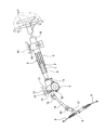
- FIG. 25 shows a conventional example of an electric power steering apparatus including a tilt mechanism and a telescopic mechanism.
- the steering device includes a steering shaft 2 that fixes a steering wheel 1 at a rear end portion, a steering column 3 that rotatably supports the steering shaft 2 on its inner diameter side, and an electric assist for applying auxiliary torque to the steering shaft 2.
- a device 4 and a steering gear unit 6 for pushing and pulling a pair of left and right tie rods 5 based on the rotation of the steering shaft 2 are provided.
- the front-back direction in this specification means the front-back direction of a vehicle body.
- the steering shaft 2 can transmit a rotational force and can be axially displaced relative to the inner shaft 7 disposed on the front side and the outer shaft 8 disposed on the rear side.
- the structure can be expanded and contracted in the axial direction.
- the steering column 3 has a structure capable of extending and contracting in the axial direction by combining the inner column 9 disposed on the front side and the outer column 10 disposed on the rear side so as to allow relative displacement in the axial direction. It has become.
- the outer shaft 8 is rotatably supported inside the outer column 10 in a state where axial displacement with respect to the outer column 10 is suppressed.
- the front end portion of the inner column 9 is coupled and fixed to the rear end surface of the housing 11 constituting the electric assist device 4.
- the inner shaft 7 is inserted into the housing 11, and a front end portion thereof is coupled to an input shaft constituting the electric assist device 4.
- the front end portion of the output shaft 12 constituting the electric assist device 4 connected to the input shaft via a torsion bar protrudes from the front end surface of the housing 11, so that the universal joint 18, the intermediate shaft 19, and another universal shaft are provided.
- the joint 20 is connected to the input shaft 21 of the steering gear unit 6 via the joint 20.
- the inner column 9 is supported on a part of the vehicle body 14 via the housing 11 by the front support bracket 13.
- the front support bracket 13 swings the housing 11 around the tilt pivot shaft 15 supported by the front support bracket 13 and extending in the width direction of the vehicle body 14 (front and back in FIG. 25). Support movably.
- the intermediate part of the outer column 10 is supported by a part of the vehicle body 14 by the rear support bracket 16.
- the outer column 10 has a fixed state in which the rear support bracket 16 cannot be moved back and forth and moved up and down, and a non-fixed state in which the back and forth movement and vertical movement are enabled. Supported to be switchable.
- various structures have been conventionally known and are not a feature of the present invention, and thus detailed description thereof will be omitted.
- the adjustment handle 17 when adjusting the height position and the front-rear position of the steering wheel 1, the adjustment handle 17 (see FIG. 26) is rotated in a predetermined direction (usually downward).
- the intermediate portion of the outer column 10 is set in an unfixed state with respect to the rear support bracket 16.
- the height position of the steering wheel 1 is adjusted by swinging the steering column 3 about the tilt pivot shaft 15.
- the front / rear position of the steering wheel 1 is adjusted by extending / contracting the steering column 3 and the steering shaft 2.
- the adjustment handle 17 is rotated in the direction opposite to the predetermined direction (usually upward), thereby fixing the intermediate portion of the outer column 10 with respect to the rear support bracket 16.
- the electric assist device 4 detects the direction and magnitude of this torque with a torque sensor provided in the housing 11, and detects the detected torque. Accordingly, the electric motor 22 supported on the outer surface of the housing 11 is configured to apply an auxiliary torque (assist force) to the output shaft 12 via a worm-type speed reducer provided in the housing 11. .
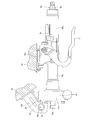
- FIGS. 26 to 31 show a first example of a conventional structure of a steering column support device for an electric power steering device in which a bush is assembled to a tilt pivot portion.
- the front support bracket 13a is made of a metal plate such as a steel plate, and is spaced apart in the width direction of the vehicle body 14 (the front and back directions in FIGS. 26 and 30 and the left and right directions in FIGS. 27, 28, and 29). It has a pair of support plate parts 23 parallel to each other. Further, the tilt pivot shaft 15 a is disposed in the width direction of the vehicle body 14 in a state of being spanned between portions near the lower ends of the pair of support plate portions 23.
- the tilt pivot shaft 15a includes a tilt bolt 24 made of a metal material such as steel, and a cylindrical sleeve 25 made of a metal material such as steel or aluminum alloy.
- the tilt bolt 24 is inserted into a pair of circular holes 26 provided concentrically with each other at the lower end portion of the pair of support plate portions 23, and is connected to a male screw portion provided at the distal end portion of the flange portion.
- the nut 27 is screwed and further tightened, so that the nut 27 is attached between the support plate portions 23.
- the sleeve 25 is clamped and fixed between the support plate portions 23 based on the tightening of the nut 27 in a state where the sleeve 25 is externally fitted to the flange portion of the tilt bolt 24.
- the housing 11a constituting the electric assist device 4a is made of a metal material such as an aluminum alloy, and a swing bracket 28 is integrally provided at a front end portion thereof.
- An insertion hole 29 is provided in the width direction of the vehicle body 14 at the tip of the swing bracket 28.
- the inner peripheral surface of the insertion hole 29 is configured by a stepped cylindrical surface in which the inner diameter dimension at both axial end portions is slightly larger than the inner diameter dimension at the axial intermediate portion.
- the axial end portions and the axial intermediate portion of the stepped cylindrical surface are concentric with each other.
- the swing bracket 28 With the front end portion or intermediate portion of the swing bracket 28 being disposed between the support plate portions 23, the swing bracket 28 is inserted into the support plate via the tilt bolt 24 and the sleeve 25 that pass through the insertion hole 29.
- the housing 11a and the steering column 3a are supported with respect to the front support bracket 13a so as to be able to swing around the tilt pivot shaft 15a.
- a pair of bushes 30 are externally fitted to both ends in the axial direction of the sleeve 25 constituting the tilt pivot shaft 15a.
- Each bush 30 is formed in a circular tube shape as a whole by an elastic material including a synthetic resin such as polyamide resin and an elastomer such as rubber or vinyl, or a low friction material such as an oil-containing metal.
- an annular (outward flange-like) side plate portion 32 extending radially outward from one axial end of the cylindrical portion 31.
- the cylindrical portion 31 of the bush 30 is sandwiched between the axial end portions of the outer peripheral surface of the sleeve 25 and the axial end portions of the inner peripheral surface of the insertion hole 29 so that there is no rattling in the radial direction. Is done.
- the side plate portions 32 of the bush 30 are sandwiched between both side surfaces in the width direction of the swing bracket 28 and the inner side surface of the support plate portion 23 so that there is no backlash in the axial direction.
- the swing bracket 28 is centered on the tilt pivot shaft 15a when the height position of the steering wheel 1 is adjusted.
- the tilt pivot shaft 15a and the swing bracket 28 are not directly rubbed with each other, but the support plate portion 23 and the swing bracket 28 are also prevented from being rubbed directly. Therefore, it is possible to avoid a situation in which a gap that causes rattling is generated in the tilt pivot portion constituted by these members due to wear and plastic deformation that are caused by direct friction between these members.
- the assist reaction force which is the reaction force
- the swing bracket 28 constituting the housing 11a receives an assist reaction force against the tilt pivot shaft 15a and the support plate portion 23, and tends to be displaced and inclined in a direction opposite to the rotation direction of the output shaft 12a.
- the bush 30 supports the assist reaction force while being elastically compressed between the tilt pivot shaft 15a and the support plate portion 23 and the swing bracket 28 or being pressed in the compression direction. The displacement and inclination of the swing bracket 28 are suppressed. This prevents the swing bracket 28, the tilt pivot shaft 15a and the support plate portion 23 from rubbing directly.
- the axial length of the cylindrical portion 31 is ensured in order to ensure the supporting ability of the anti-assist force by the bush 30, that is, the ability to suppress the displacement and inclination of the swing bracket 28.
- the radial direction height of the side-plate part 32 is enlarged to some extent, respectively.
- the inner side surface of the support plate portion 23 and both side surfaces of the swing bracket 28 and both side surfaces of the side plate portion 32 are all parallel planes. For this reason, in a neutral state where no assist force is generated, both side surfaces of the side plate portion 32, the inner side surface of the support plate portion 23, and both side surfaces of the swing bracket 28 are in contact with each other almost entirely.
- both the inner and outer peripheral surfaces of the cylindrical portion 31 and the mating surface are increased by the amount of the axial length of the cylindrical portion 31 and the radial height of the side plate portion 32.
- the contact area with the inner peripheral surface of the insertion hole 29 of the moving bracket 28 and the contact between both side surfaces of the side plate portion 32 and the mating surface is larger.
- FIGS. 32A and 32B show second and third examples of a conventional structure of a steering column support device for an electric power steering device described in Japanese Patent Application Laid-Open No. 2008-30728. Is shown.
- the inner circumferential surface of the insertion hole 29a formed in the swing bracket 28a is away from the outer circumferential surface of the cylindrical portion 31a constituting the bush 30a (30b) as it goes from the central portion in the axial direction toward both ends. It is inclined to.
- substantially cylindrical gaps 33 each having a wedge-shaped cross section are provided on both sides of the axially central portion between the inner peripheral surface of the insertion hole 29a and the outer peripheral surface of the cylindrical portion 31a. .
- the outer surface of the side plate portion 32a constituting the bush 30a is away from the inner surface of the support plate portion 23 as it goes radially outward. It is inclined to.
- a substantially annular gap 34 a having a wedge-shaped cross section is provided between the outer side surface of the side plate portion 32 a and the inner side surface of the support plate portion 23.
- a substantially annular gap 34b having a wedge-shaped cross section is provided between the inner surface of the side plate portion 32a and the outer surface of the swing bracket 28a. Based on the presence of the gaps 33, 34a, 34b thus provided, the swing bracket 28a (the central axis of the insertion hole 29a) is easily inclined with respect to the central axis of the tilt pivot shaft 15a.
- the guide direction of the part may be inclined with respect to a virtual plane orthogonal to the central axis of the tilt pivot shaft 15a.
- the swinging bracket 28a is inclined with respect to the central axis of the tilt pivot shaft 15a.
- the swinging direction of the steering column 3a at the time of adjustment and the guide direction of the intermediate portion of the steering column 3a are in agreement with each other. Therefore, it is possible to avoid a situation in which the adjustment operation of the height position of the steering wheel 1 becomes poor due to the mismatch between the swing direction and the guide direction.
- the contact area between the inner peripheral surface of the insertion hole 29a and the outer peripheral surface of the cylindrical portion 31a is small based on the presence of the gap 33. For this reason, the frictional force which acts between the internal peripheral surface of the through-hole 29a and the outer peripheral surface of the cylindrical part 31a can be made small. Further, based on the presence of the gaps 34a and 34b, in the second example of the conventional structure, the contact surface pressure between the both side surfaces of the swing bracket 28a and the inner surfaces of the side plate portions 32a and 32b (see FIG. 32A). In the third example of the conventional structure, these contact areas (see FIG. 32B) can be reduced.
- the frictional force acting between them can be stably reduced, and the height position of the steering wheel 1 can be adjusted by causing slippage between the swing bracket 28a and the bushes 30a, 30b. It is possible to improve the workability of the height position adjustment by keeping the resistance when performing the operation low.
- the support rigidity of the swing bracket 28a by the tilt pivot shaft 15a is reduced based on the presence of the gap 33, and the steering wheel 1 (see FIG. 25) is reduced. Support rigidity is also lowered. As a result, the driver may feel uncomfortable. Further, due to the assist reaction force generated at the time of steering, the swing bracket 28a is relatively inclined with respect to the central axis of the tilt pivot shaft 15a based on the presence of the clearance 33 among the clearances 33, 34a, 34b. To do. This may also cause the driver to feel uncomfortable.
- the present invention secures the supporting ability of the anti-assist force by the pair of bushes, and adjusts the height position of the steering wheel, and the surfaces of these bushes.
- An object of the present invention is to realize a structure of a steering column support device for an electric power steering device that can stably suppress the frictional force acting between the opposite surface and the opposite surface.
- the steering column support device of the present invention is particularly applied to an electric power steering device having a tilt mechanism.
- the steering column support device of the present invention includes a front support bracket, a tilt pivot shaft, a swing bracket, and a pair of bushes.
- the front support bracket has a pair of support plate portions that are fixed to the vehicle body and arranged in parallel to each other in the width direction of the vehicle body.
- the tilt pivot shaft is disposed in the width direction of the vehicle body in a state of being spanned between the support plate portions.
- the swing bracket is provided in a part of the housing of the electric assist device, has an insertion hole through which the tilt pivot shaft is inserted, and supports a steering column that rotatably supports the steering shaft via the housing. To do.
- the pair of bushes are made of an elastic material or a low friction material, and each is formed in a ring shape.
- the bushes are respectively fitted on both ends in the axial direction of the tilt pivot shaft, and each is a cylinder sandwiched between the outer peripheral surface of the tilt pivot shaft and the inner peripheral surface of the insertion hole.
- an annular side plate portion that extends radially outward from one axial end portion of the cylindrical portion and is sandwiched between a side surface of the swing bracket and an inner side surface of the support plate portion.
- each of these bushes at least in a neutral state where the assist force applied to the steering shaft by the electric assist device is not generated, a part of at least one of the peripheral surfaces of the cylindrical portion, or A part of at least one of both side surfaces of the side plate portion is provided with a thinning portion that is in a non-contact state with a mating surface facing these surfaces.
- the thinning portion is constituted by a recess provided on at least one of both side surfaces of the side plate portion.
- each of the bushes at least one radial half of at least one of both side surfaces of the side plate portion is formed with a main contact surface portion that contacts the mating surface at least in the neutral state.
- the secondary contact surface portion that does not contact the counterpart surface and contacts the counterpart surface only when the side plate portion is elastically deformed by the reaction force of the assist force.
- the concave portion can be formed by the sub contact surface portion.
- the main contact surface portion can be provided on the inner diameter side
- the sub contact surface portion can be provided on the outer diameter side.
- the main contact surface portion can be provided on the outer diameter side
- the sub contact surface portion can be provided on the inner diameter side.
- the recess may be provided in at least one radial intermediate portion of both side surfaces of the side plate portion.
- the concave portion is provided at a plurality of locations in the circumferential direction of at least one of the both side surfaces of the side plate portion, and is a concave groove extending in the radial direction, or at least one of both side surfaces of the side plate portion. It can be constituted by a concave groove extending in the circumferential direction.
- the concave groove can be formed over the entire circumference of at least one of the side surfaces of the side plate portion.
- groove can also be comprised by the several circular arc-shaped ditch
- the thinning portion is formed so as to penetrate through the thickness direction in at least one circumferential direction of at least one of the cylindrical portion and the side plate portion.
- the thinning portion is a discontinuous portion in which at least one of the cylindrical portion and the side plate portion is discontinuous in at least one circumferential direction, the cylindrical portion and the side plate. It can be configured by a notch that opens to at least one end edge of the portion, or a through hole that penetrates in the thickness direction of at least one of the cylindrical portion and the side plate portion.
- the diameter of the portion of the outer peripheral surface of the tilt pivot shaft and the inner peripheral surface of the insertion hole that holds the cylindrical portion of the bush does not change in the axial direction. It is preferable that each cylindrical portion of the bush is supported as a cylindrical surface without rattling between the outer peripheral surface of the tilt pivot shaft and the inner peripheral surface of the insertion hole.
- the surface of these bushes (the circumference of the cylindrical portion).
- the frictional force acting between the surface and the side surface of the side plate portion) and the opposing surface facing this surface can be stably kept low.
- at least a part of the peripheral surface of the cylindrical surface constituting the bush or the side surface of the side plate portion is in a neutral state where at least assist force is not generated, and is in a non-contact state with a mating surface facing these surfaces. It has a thinning part.
- the contact area between the surface of the bush and the mating surface is reduced when the contact area between the surface of the bush and the mating surface is reduced by the thickness of the thinned portion, and becomes a resistance when adjusting the height position of the steering wheel.
- the frictional force acting on the steering wheel is stably kept low, thereby improving the workability of adjusting the height position of the steering wheel.
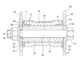
- FIG. 1 is an enlarged view showing a tilt pivot portion of a first example of an embodiment of the present invention in a cut state.
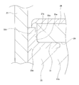
- FIG. 2 is an enlarged view of part a in FIG.
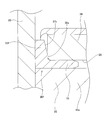
- FIG. 3 is a view similar to FIG. 2 showing a second example of the embodiment of the present invention.
- FIG. 4 is a view similar to FIG. 2, showing a third example of the embodiment of the present invention.
- FIG. 5 is a view similar to FIG. 2, showing a fourth example of the embodiment of the present invention.
- FIG. 6 is a view similar to FIG. 28, showing a fifth example of the embodiment of the present invention.
- FIG. 7 is an enlarged view of part b of FIG. FIG.
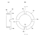
- FIG. 8 is a view of the bush incorporated in the fifth example of the embodiment of the present invention as seen from the outer surface side of the side plate portion.
- FIGS. 9A to 9C are views showing three examples of concave portions provided on the side surface of the side plate portion, which can be incorporated in the fifth example of the embodiment of the present invention.
- FIG. 10 is a view similar to FIG. 7, showing a sixth example of the embodiment of the present invention.
- FIG. 11 is a view similar to FIG. 7, showing a seventh example of the embodiment of the present invention.
- FIG. 12 is a view similar to FIG. 1, showing an eighth example of the embodiment of the present invention.
- 13 is a cross-sectional view taken along the line cc of FIG. FIG.
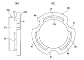
- FIG. 14 (A) is a side view of the bush incorporated in the eighth example of the embodiment of the present invention
- FIG. 14 (B) is a view seen from the right side of FIG. 14 (A).
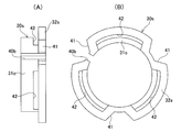
- 15A is a cross-sectional view (a cross-sectional view taken along the line dd in FIG. 15B) of the bush incorporated in the ninth example of the embodiment of the present invention.
- FIG. 15B is a cross-sectional view of FIG. It is the figure seen from the right side.
- FIG. 16 is a view similar to FIG. 14 showing a bush incorporated in the tenth example of the embodiment of the present invention.
- FIG. 17 is a view similar to FIG. 14 showing a bush incorporated in the eleventh example of the embodiment of the present invention.
- FIG. 16 is a view similar to FIG. 14 showing a bush incorporated in the eleventh example of the embodiment of the present invention.
- FIG. 18 is a view similar to FIG. 14 showing a bush incorporated in the twelfth example of the embodiment of the present invention.
- FIG. 19 is a view similar to FIG. 14 showing a bush incorporated in the thirteenth example of the embodiment of the present invention.
- FIG. 20 is a view similar to FIG. 14 showing a bush incorporated in the fourteenth example of the embodiment of the present invention.
- FIG. 21 is a view similar to FIG. 14 showing a bush incorporated in the fifteenth example of the embodiment of the present invention.
- FIG. 22 is a view similar to FIG. 14 showing a bush incorporated in the sixteenth example of the embodiment of the present invention.
- FIG. 23 is a view similar to FIG. 14 showing a bush incorporated in the seventeenth example of the embodiment of the present invention.
- FIG. 19 is a view similar to FIG. 14 showing a bush incorporated in the thirteenth example of the embodiment of the present invention.
- FIG. 20 is a view similar to FIG. 14 showing a bush incorporated in the
- FIG. 24 shows a structure reference in which the force required to adjust the height position of the steering wheel can be reduced, and the amount by which the swing bracket tilts with respect to the center axis of the tilt pivot shaft can be suppressed by the assist reaction force. It is a figure similar to FIG. 2 which shows an example.
- FIG. 25 is a schematic side view showing an example of a conventional structure of an electric power steering apparatus provided with a tilt mechanism in a state where a part thereof is cut.
- FIG. 26 is a side view of an essential part showing a first example of a conventional structure of a steering column support device.
- FIG. 27 is a view from the left of FIG. 26, showing the tilt pivot portion in a cut state.
- FIG. 28 is an enlarged view of part e in FIG. FIG.
- FIG. 29 is an enlarged view of part f in FIG. 30 is a cross-sectional view taken along the line gg of FIG.
- FIG. 31 is a view similar to FIG. 14 showing the bush incorporated in the first example of the conventional structure.
- FIG. 32 (A) is a view similar to FIG. 29 showing a bush incorporated in the second example of the conventional structure of the steering column support device, and
- FIG. 32 (B) is a third view of the conventional structure of the steering column support device. It is a figure similar to FIG. 29 which shows the bush integrated in an example.
- the steering column support device of the present invention is particularly applied to an electric power steering device provided with a tilt mechanism.
- the steering column support device of the present invention includes a front support bracket 13a, a tilt pivot shaft 15a, a swing bracket 28, and a pair of bushes 30c.
- the front support bracket 13a has a pair of support plate portions 23 that are fixed to the vehicle body and arranged in parallel with each other in the width direction of the vehicle body.
- the tilt pivot shaft 15a is disposed in the width direction of the vehicle body in a state of being spanned between the support plate portions 23.
- the swing bracket 28 is provided in a part of the housing of the electric assist device, and has an insertion hole 29 through which the tilt pivot shaft 15a is inserted.
- Each bush 30c is made of an elastic material including a synthetic resin such as a polyamide resin and an elastomer such as rubber or vinyl, or is made of a low friction material such as an oil-impregnated metal.
- a cylindrical portion 31 that is externally fitted to both axial ends of the pivot shaft 15a and is sandwiched between the outer peripheral surface of the tilt pivot shaft 15a and the inner peripheral surface of the insertion hole 29;
- the ring-shaped side plate portion 32c extends radially outward from one end in the axial direction and is sandwiched between the side surface of the swing bracket 28 and the inner surface of the support plate portion 23.
- the feature of this example is the shape of the outer surface of the side plate portion 32c of each bush 30c and the structure of the installation location of the cylindrical portion 31 of the bush 30c.
- the structure and operation of other parts are the same
- the inner surface facing the both side surfaces of the swing bracket 28 is a single ring surface.
- step portions 35 are formed on the inner peripheral portions of the outer surfaces facing the inner surfaces of the pair of support plate portions 23 constituting the front support bracket 13a among the both side surfaces of the side plate portion 32c. ing.
- the outer side surface of the side plate portion 32c is positioned on the inner side in the axial direction with respect to the inner side portion which is the other half portion of the radially opposite side portions sandwiching the step portion 35. It is a stepped ring with a stepped back.
- the inner diameter side portion of the both radial side portions sandwiching the step portion 35 is a single ring-shaped main contact surface portion 36, and the outer diameter side portion is concentric with the main contact surface portion 36 and has a single annular shape sub-portion.
- the contact surface portion 37 is used. In the neutral state where the assist reaction force is not applied, almost the entire inner surface of the side plate portion 32c is brought into contact with both side surfaces of the swing bracket 28, respectively, as shown in FIGS. On the other hand, the outer side surface of the side plate portion 32 c makes only the main contact surface portion 36 of the radially inner portion contact the inner side surface of the support plate portion 23.
- the sub-contact surface portion 37 of the radially outer portion is not in contact with the inner side surface of the support plate portion 23, and with respect to the inner side surface of the support plate portion 23, It is opposed through a small gap.
- the cylindrical portion 31 constituting the bush 30c is a cylindrical surface whose diameter does not change with respect to the axial direction, both axial end portions of the outer peripheral surface of the sleeve 25 constituting the tilt pivot shaft 15a, and the swing bracket 28.
- the insertion hole 29 is sandwiched between both ends of the inner peripheral surface in the axial direction. That is, in the neutral state, as shown in FIGS. 1 and 2, almost the entire inner and outer peripheral surfaces of the cylindrical portion 31 (at least the portions excluding the chamfered portions on both the inner and outer peripheral edges in the radial direction) In this state, both end portions of the outer peripheral surface of 25 and both end portions of the inner peripheral surface of the insertion hole 29 are in contact with no gap.
- the support rigidity of the swing bracket 28 by the tilt pivot shaft 15a can be sufficiently secured, and the swing bracket 28 is made to be the central axis of the tilt pivot shaft 15a by the assist reaction force generated at the time of steering. Can be sufficiently suppressed.
- the resistance at the time of adjusting the height position of the steering wheel 1 can be kept low in a state where the durability of the side plate portion 32c constituting the bush 30c is sufficiently ensured.
- the portions sandwiching the cylindrical portion 31 constituting the bush 30c are respectively axially A cylindrical surface whose diameter does not change. And, in a neutral state, these cylindrical surfaces are respectively removed from the entire inner and outer peripheral surfaces of the cylindrical portion 31 (at least portions excluding the chamfered portions at both ends) except for a minute gap necessary for relative rotation, It is in contact with almost no gap. Therefore, the support rigidity of the swing bracket 28 by the tilt pivot shaft 15a can be sufficiently secured.
- the outer side surface of the side plate portion 32c constituting the bush 30c is mainly in relation to the inner side surface of the support plate portion 23. Contact is made only at the contact surface portion 36, and contact is not made at the sub contact surface portion 37. For this reason, in the neutral state, the contact area between the outer surface of the side plate portion 32c and the inner surface of the support plate portion 23 is reduced, and the frictional force acting on the contact portion between these outer surface and inner surface is reduced. Can do. Therefore, when the height position of the steering wheel 1 is adjusted, the resistance when adjusting the height position of the steering wheel 1 is reduced by sliding the outer surface of the side plate portion 32c and the inner surface of the support plate portion 23. It can be kept low.
- the swinging bracket 28 is displaced toward one of the support plate portions 23 of the pair of support plate portions 23 by the assist reaction force, and the center axis of the tilt pivot shaft 15a.
- the inclination tends to be inclined
- at least a part of the side plate portion 32c in the circumferential direction is pushed by the both side surfaces of the swing bracket 28 to be elastically deformed.
- the outer surface of the elastically deformed portion of the side plate portion 32 c comes into contact with the inner surface of the support plate portion 23 not only at the main contact surface portion 36 but also at the sub contact surface portion 37.
- the assist reaction force can be supported in a wide range including not only a portion corresponding to the main contact surface portion 36 but also a portion corresponding to at least a part of the sub contact surface portion 37.
- the support plate 23 is deformed. Due to the deformation of the support plate portion 23, the outer diameter side of the side plate portion 32 c is more strongly compressed by the deformation of the support plate portion 23.
- the escape by the sub-contact surface portion 37 is made in this portion, the abnormal wear of the side plate portion 32c is prevented.
- FIG. 3 shows a second example of the embodiment of the present invention.
- the configuration of both side surfaces of the side plate portion 32d is reversed from the case of the first example of the embodiment. That is, in the case of this example, the outer side surface of the side plate portion 32d is a single ring surface, and the inner side surface of the side plate portion 32d is the main contact surface portion 36a on the inner diameter side and the sub contact surface portion 37a on the outer diameter side. It is set as the stepped ring surface which continued through the step part 35a. Then, in the neutral state where the assist reaction force is not acting, as shown in FIG.
- the entire outer side surface of the side plate portion 32d is brought into contact with the inner side surface of the support plate portion 23, and the inner side surface of the side plate portion 32d is Of these, only the main contact surface portion 36 a is in contact with the side surface of the swing bracket 28. Also in the case of this example, based on the presence of the main contact surface portion 36a and the sub contact surface portion 37a, the same operational effects as in the case of the first example of the embodiment can be achieved. The structure and operation of the other parts are the same as in the first example of the embodiment.
- FIG. 4 shows a third example of the embodiment of the present invention.
- the configuration of the sub-contact surface portion 37b provided on the outer diameter side portion of the outer surface of the side plate portion 32e is different from that of the first example of the embodiment. Yes. That is, in the case of this example, the inner peripheral edge of the sub-contact surface portion 37b is directly connected to the outer peripheral edge of the main contact surface portion 36 provided on the inner diameter side portion without a stepped portion. Further, the sub-contact surface portion 37b is an inclined surface that is inclined in a direction away from the inner surface of the support plate portion 23 as it goes outward in the radial direction.
- the cross-sectional shape of the sub-contact surface portion 37b that is an inclined surface is a linear shape, but this cross-sectional shape is curved in a direction that is convex with respect to the inner surface of the support plate portion 23. It can also be a curved shape.
- the main contact surface portion 36 provided on one side surface of the side plate portion 32e constituting the bush 30e is a plane parallel to the mating surface, and the sub-contact surface portion 37b is further away from the mating surface as it goes radially outward.
- the inclined surface is inclined in the direction of leaving.
- the entire one side surface of the side plate portion is an inclined surface that inclines in a direction away from the mating surface as it goes outward in the radial direction, and the portion that contacts the mating surface in the neutral state is the main contact surface portion.
- the portion that does not come into contact with the mating surface can be used as the sub-contact surface portion.
- Other configurations and operations are the same as those in the first example of the embodiment.
- FIG. 5 shows a fourth example of the embodiment of the present invention.
- the configuration of the sub-contact surface portion 37c provided on the outer diameter side portion of the inner side surface of the side plate portion 32f is different from that of the second example of the embodiment for each of the pair of bushes 30f. Yes. That is, in the case of this example, the inner peripheral edge of the sub-contact surface portion 37c is directly connected to the outer peripheral edge of the main contact surface portion 36a provided on the inner diameter side portion without a stepped portion. Further, the sub-contact surface portion 37c is an inclined surface that is inclined in a direction away from the side surface of the swing bracket 28 as it goes outward in the radial direction. Other configurations and operations are the same as those in the second and third examples of the embodiment.
- FIG. 6 to 8 show a fifth example of the embodiment of the present invention.
- an annular groove 38 that is continuous over the entire circumference is provided concentrically with the side plate portion 32g in the radially intermediate portion of the outer side surface of both side surfaces of the side plate portion 32g constituting the bush 30g. . Then, at least in a neutral state where the assist reaction force is not acting, only the portion of the outer surface of the side plate portion 32g that is out of the concave groove 38 is brought into contact with the inner surface of the support plate portion 23.
- the steering column support device of the present example in order to secure the support capability of the counter-assist force by the side plate portion 32g constituting the bush 30g, even when trying to sufficiently secure the radial height of the side plate portion 32g, it is neutral. In this state, the contact area between the outer side surface of the side plate portion 32 g and the inner side surface of the support plate portion 23 can be suppressed by the opening area of the groove 38. For this reason, it acts on the contact portion between the outer side surface of the side plate portion 32g and the inner side surface of the support plate portion 23 in the neutral state, which becomes resistance when adjusting the height position of the steering wheel 1 (see FIG. 25). The frictional force can be stably reduced. Therefore, it is possible to avoid a situation in which the frictional force is large and unstable, and workability when the height position of the steering wheel 1 is adjusted is deteriorated.
- the outer plate end portion of the side plate portion 32c is bent because the concave groove 38 is formed in the side plate portion 32c. It is easy to absorb the deformation of the side plate portion 32c, and abnormal wear of the side plate portion 32c is prevented. Therefore, it is possible to suppress the sag of the side plate portion 32c due to the repeated load of the assist reaction force, sufficiently ensure the durability of the side plate portion 32c, and prevent the occurrence of rattling in the tilt pivot portion for a long period of time. .
- a recessed part provided in the side surface of the side-plate part which comprises a bush it is not restricted to the annular recessed groove 38 continued over the perimeter, About the circumferential direction as shown to FIG. 9 (A) and FIG. 9 (B).
- Other configurations and operations are the same as those of the first example of the embodiment of the present invention and the first example of the conventional structure.
- FIG. 10 shows a sixth example of the embodiment of the present invention.
- annular concave grooves 38c that are continuous over the entire circumference are formed in the radially intermediate portion of the inner side surface (the side surface on the swing bracket 28 side) of the side plate portion 32h constituting the pair of bushes 30h.
- FIG. 11 shows a third example of the embodiment of the present invention.
- the concave grooves 38 and 38c are provided on both side surfaces of the side plate portion 32i constituting the pair of bushes 30i. For this reason, the resistance at the time of adjusting the vertical position of the steering wheel 1 (see FIG. 25) can be more stably suppressed to a low level.
- Other configurations and operations are the same as those in the fifth and sixth examples of the embodiment.
- the bush 30j has the discontinuous part 40 which is a thinning part at one place in the circumferential direction.
- the discontinuous portion 40 penetrates the cylindrical portion 31b in the thickness direction (the radial direction of the bush 30j) and penetrates the side plate portion 32j in the thickness direction (the axial direction of the bush 30j). Therefore, the bush 30j has a partially annular shape that is discontinuous in the circumferential direction at this portion.
- the width dimension of the discontinuous portion 40 in the circumferential direction is constant with respect to the axial direction of the cylindrical portion 31b at the portion corresponding to the cylindrical portion 31b and with respect to the radial direction of the side plate portion 32j at the portion corresponding to the side plate portion 32j. .
- the circumference The area of each contact portion that may cause a directional slip can be suppressed by the opening area of the discontinuous portion 40 in the contact portion. Therefore, even when any of the contact portions slips in the circumferential direction, the contact portion acts as a resistance when adjusting the height position of the steering wheel 1 (see FIG. 25). The frictional force can be stably kept low. Therefore, the workability when adjusting the height position of the steering wheel 1 can be improved.
- the side plate portion 32c can be prevented from abnormal wear. Therefore, it is possible to suppress the sag of the side plate portion 32c due to the repeated load of the assist reaction force, sufficiently ensure the durability of the side plate portion 32c, and prevent the occurrence of rattling in the tilt pivot portion for a long period of time. .
- grease can be applied to the surface of the bush 30j to reduce the frictional force acting on the contact portion between the surface of the bush 30j and the mating surface.
- the inside of the discontinuous portion 40 that is the thinning portion can be used as a grease reservoir.
- Other configurations and operations are the same as those of the first example, the fifth example, and the first example of the conventional structure of the embodiment of the present invention.
- the structure of this example can be additionally applied to the structures of the first to seventh examples of the embodiment of the present invention.
- FIG. 15 shows a ninth example of the embodiment of the invention.
- the bush 30k has the discontinuous part 40 at one place in the circumferential direction, as in the case of the eighth example of the embodiment.
- These three locations are also provided with discontinuous portions 40a, which are thinning portions.
- these discontinuous portions 40a are discontinuous portions only for the side plate portions 32k, and the cylindrical portion 31b is continuous.
- the contact area between the both side surfaces of the side plate portion 32k and the mating surface is set as a discontinuous portion on these both side surfaces. This can be further reduced by the opening area of 40a. For this reason, the resistance at the time of adjusting the height position of the steering wheel 1 (refer FIG. 25) can be suppressed more stably and low.
- Other configurations and operations are the same as those in the eighth example of the embodiment.
- FIG. 16 shows a tenth example of the embodiment of the present invention
- FIG. 17 shows an eleventh example of the embodiment of the present invention.
- the side plate portions 32m and 32n are arranged at a plurality of positions at equal intervals in the circumferential direction (three in the case of FIG. 16, FIG. 17).
- notches 41 and 41a are provided in the outer peripheral edges of the side plate portions 32m and 32n, each of which is a thinning portion.
- the contact area between both side surfaces of the side plate portions 32m and 32n and the opposing surface facing these both side surfaces is represented by notches 41 on these both side surfaces. It can be suppressed by the opening area 41a.
- Other configurations and operations are the same as those in the eighth example of the embodiment.
- FIG. 18 shows a twelfth example of the embodiment of the present invention
- FIG. 19 shows a thirteenth example of the embodiment of the present invention
- the bushes 30o and 30p of the twelfth example and the thirteenth example of these embodiments have a plurality of circumferentially equidistant locations (see FIG. 18) of continuous portions of the cylindrical portions 31c and 31d and the side plate portions 32o and 32p, respectively.
- three holes are provided, and four holes in the case of FIG.
- the through hole 42 penetrates the cylindrical portion 31c in the thickness direction (radial direction) and penetrates the side plate portion 32o in the thickness direction (axial direction).
- the through hole 42a penetrates the cylindrical portion 31d in the thickness direction and penetrates the side plate portion 32p in the thickness direction.
- the contact area between both side surfaces of the side plate portions 32o and 32p and the mating surface, and both the inner and outer peripheral surfaces of the cylindrical portions 31c and 31d and the mating surface Can be suppressed by the opening area of the through holes 42 and 42a, respectively.
- Other configurations and operations are the same as those in the eighth example of the embodiment.
- FIG. 20 shows a fourteenth example of the embodiment of the present invention
- FIG. 21 shows a fifteenth example of the embodiment of the present invention.
- the bushes 30q and 30r of the fourteenth example and the fifteenth example of these embodiments are provided with a plurality of cutouts 41 or 41a similar to those in the tenth example or the eleventh example of the embodiment, respectively.
- a plurality of through holes 42 or 42a similar to those in the twelfth example or the thirteenth example are alternately arranged at equal intervals in the circumferential direction.
- the resistance when adjusting the height position of the steering wheel 1 is reduced. , More stable and low.
- Other configurations and operations are the same as those in the tenth or eleventh example of the embodiment and the twelfth or thirteenth example of the embodiment.
- FIG. 22 shows a sixteenth example of the embodiment of the present invention
- FIG. 23 shows a seventeenth example of the embodiment of the present invention.
- the bushes 30s and 30t of the sixteenth example and the seventeenth example of these embodiments each have a through hole 42 at one location in the circumferential direction of the bush 30q of the fourteenth example of the embodiment or the bush 30r of the fifteenth example.
- 42a is provided with a discontinuous portion 40b which is a thinned portion.
- the bushes 30s and 30t are provided by the discontinuous portion 40b.
- the contact area between the surface and the mating surface can be suppressed. For this reason, the resistance at the time of adjusting the height position of the steering wheel 1 (refer FIG. 25) can be suppressed more stably and low.
- Other configurations and operations are the same as those of the fourteenth example or the fifteenth example of the embodiment.
- FIG. 24 is out of the technical scope of the present invention, but as with the present invention, the height of the steering wheel 1 (see FIG. 25) is secured while ensuring the support capability of the counter-assist force by the pair of bushes.
- a structure is shown in which the frictional force acting between the surface of the bush and the mating surface opposite to the surface can be stably kept low.
- the radial height of the side plate portion 32u constituting the bush 30u is lowered, and the ridge portion 43 protruding from the radial intermediate portion of the side surface of the swing bracket 28a is used as the outer diameter of the side plate portion 32u.
- the distal end surface of the protrusion 43 is placed close to and opposed to the inner surface of the support plate 23.
- the contact area between both side surfaces of the side plate portion 32u and the mating surface is reduced by the amount corresponding to the reduction in the radial height of the side plate portion 32u,
- the frictional force acting on the contact portion can be kept low. For this reason, the resistance at the time of adjusting the height position of the steering wheel 1 can be suppressed by that much.
- the swinging bracket 28a tends to be displaced and inclined in the axial direction due to the assist reaction force, the tip surface of the ridge portion 43 abuts against the inner surface of the support plate portion 23. Such displacement and tilt are prevented from becoming larger.
- a buffering action based on elastic deformation of the bush 30u can be obtained until the tip surface of the ridge 43 contacts the inner surface of the support plate 23.
Landscapes
- Engineering & Computer Science (AREA)
- Chemical & Material Sciences (AREA)
- Combustion & Propulsion (AREA)
- Transportation (AREA)
- Mechanical Engineering (AREA)
- Steering Controls (AREA)
- Power Steering Mechanism (AREA)
- Sliding-Contact Bearings (AREA)
Abstract
Description
図1~図2は、本発明の実施の形態の第1例を示している。本発明のステアリングコラム支持装置は、特に、チルト機構を備えた電動式パワーステアリング装置に適用される。本発明のステアリングコラム支持装置は、前部支持ブラケット13aと、チルトピボット軸15aと、揺動ブラケット28と、1対のブッシュ30cとを備える。前部支持ブラケット13aは、車体に固定され、この車体の幅方向に離隔して配置される互いに平行な1対の支持板部23を有する。チルトピボット軸15aは、支持板部23同士の間に掛け渡された状態で、車体の幅方向に配設される。揺動ブラケット28は、電動アシスト装置のハウジングの一部に設けられ、チルトピボット軸15aが挿通する挿通孔29を有する。それぞれのブッシュ30cは、ポリアミド樹脂などの合成樹脂と、ゴムやビニルなどのエラストマーとを含む弾性材製、または、含油メタルなどの低摩擦材製で、全体が環状にそれぞれ形成され、かつ、チルトピボット軸15aの軸方向両端部にそれぞれ外嵌され、かつ、それぞれが、チルトピボット軸15aの外周面と挿通孔29の内周面との間に挟持される円筒部31と、円筒部31の軸方向一端部から径方向外方に伸長し、揺動ブラケット28の側面と支持板部23の内側面との間に挟持される円輪状の側板部32cとにより構成される。なお、本例の特徴は、それぞれのブッシュ30cの側板部32cの外側面の形状およびブッシュ30cの円筒部31の設置箇所の構造にある。その他の部分の構造および作用は、従来構造の第1例の場合と同様である。
図3は、本発明の実施の形態の第2例を示している。本例の場合には、1対のブッシュ30dのそれぞれに関して、側板部32dの両側面の構成を、実施の形態の第1例の場合と逆にしている。すなわち、本例の場合には、側板部32dの外側面を単一の円輪面とし、側板部32dの内側面を、内径側の主接触面部36aと外径側の副接触面部37aとを段部35aを介して連続させた、段付きの円輪面としている。そして、アシスト反力が作用していない中立状態で、図3に示すように、側板部32dの外側面の全体を、支持板部23の内側面に接触させるとともに、側板部32dの内側面のうち、主接触面部36aのみを、揺動ブラケット28の側面に接触させている。本例の場合も、主接触面部36aと副接触面部37aとの存在に基づいて、実施の形態の第1例の場合と同様の作用効果を奏することができる。その他の部分の構成および作用は、実施の形態の第1例の場合と同様である。
図4は、本発明の実施の形態の第3例を示している。本例の場合には、1対のブッシュ30eのそれぞれに関して、側板部32eの外側面の外径側部分に設ける副接触面部37bの構成を、実施の形態の第1例の場合と異ならせている。すなわち、本例の場合には、副接触面部37bの内周縁を、内径側部分に設けた主接触面部36の外周縁に、段部を介することなく直接連続させている。また、副接触面部37bを、径方向外方に向かうほど、支持板部23の内側面から離れる方向に傾斜した傾斜面としている。なお、本例の場合、傾斜面である副接触面部37bの断面形状を、それぞれ直線形状としているが、この断面形状を、支持板部23の内側面に対して凸となる方向に湾曲した、曲線形状とすることもできる。
図5は、本発明の実施の形態の第4例を示している。本例の場合には、1対のブッシュ30fのそれぞれに関して、側板部32fの内側面の外径側部分に設ける副接触面部37cの構成を、実施の形態の第2例の場合と異ならせている。すなわち、本例の場合には、副接触面部37cの内周縁を、内径側部分に設けた主接触面部36aの外周縁に、段部を介することなく直接連続させている。また、副接触面部37cを、径方向外方に向かうほど、揺動ブラケット28の側面から離れる方向に傾斜した傾斜面としている。その他の構成および作用は、実施の形態の第2例および第3例の場合と同様である。
図6~図8は、本発明の実施の形態の第5例を示している。本例の場合、ブッシュ30gを構成する側板部32gの両側面のうち、外側面の径方向中間部に、全周にわたり連続した円環状の凹溝38を、側板部32gと同心に設けている。そして、少なくともアシスト反力が作用していない中立状態で、側板部32gの外側面のうち、凹溝38から外れた部分のみを、支持板部23の内側面に接触させている。
図10は、本発明の実施の形態の第6例を示している。本例の場合には、1対のブッシュ30hを構成する側板部32hの内側面(揺動ブラケット28側の側面)の径方向中間部に、それぞれ全周にわたり連続した円環状の凹溝38cを、側板部32hと同心に設けている。そして、アシスト反力が発生していない中立状態で、側板部32hの内側面のうち、凹溝38cから外れた部分のみを、揺動ブラケット28の両側面に接触させている。
図11は、本発明の実施の形態の第3例を示している。本例の場合には、1対のブッシュ30iを構成する側板部32iの両側面に、凹溝38、38cを設けている。このため、ステアリングホイール1(図25参照)の上下位置を調節する際の抵抗を、より安定して低く抑えることができる。その他の構成および作用は、実施の形態の第5例および第6例の場合と同様である。
図12~図14は、本発明の実施の形態の第8例を示している。本例の場合、ブッシュ30jは、周方向の1箇所に、除肉部である不連続部40を有する。この不連続部40は、この部分において、円筒部31bを厚さ方向(ブッシュ30jの径方向)にわたって貫通するとともに、側板部32jを厚さ方向(ブッシュ30jの軸方向)にわたって貫通する。したがって、ブッシュ30jは、この部分で周方向に不連続である欠円環状となっている。不連続部40の周方向に関する幅寸法は、円筒部31bに対応する部分ではこの円筒部31bの軸方向に関して、側板部32jに対応する部分ではこの側板部32jの径方向に関して、それぞれ一定である。
図15は、本発明の実施の形態の第9例を示している。本例の場合、ブッシュ30kは、実施の形態の第8例の場合と同様に、周方向1箇所に不連続部40を有する。さらに、本例のブッシュ30kの場合には、側板部32kのうちで、不連続部40が存在する箇所を含む、円周方向等間隔の4箇所のうち、不連続部40が存在する箇所以外の3箇所にも、それぞれ除肉部である不連続部40aを設けている。ただし、これらの不連続部40aは、側板部32kについてのみ不連続部となっており、円筒部31bについては連続させている。
図16は、本発明の実施の形態の第10例を、図17は、本発明の実施の形態の第11例をそれぞれ示している。これら実施の形態の第10例および第11例の組み込まれるブッシュ30m、30nには、それぞれ、側板部32m、32nの円周方向等間隔の複数箇所(図16の場合には3箇所、図17の場合には4箇所)に、それぞれが除肉部である、側板部32m、32nの外周縁に開口する切り欠き41、41aが設けられている。
図18は、本発明の実施の形態の第12例を、図19は、本発明の実施の形態の第13例をそれぞれ示している。これら実施の形態の第12例および第13例のブッシュ30o、30pには、それぞれ、円筒部31c、31dと側板部32o、32pとの連続部の円周方向等間隔の複数箇所(図18の場合には3箇所、図19の場合には4箇所)に、それぞれ除肉部である透孔42、42aを設けている。透孔42は、円筒部31cを厚さ方向(径方向)に貫通するとともに、側板部32oを厚さ方向(軸方向)に貫通する。透孔42aは、円筒部31dを厚さ方向に貫通するとともに、側板部32pを厚さ方向に貫通する。
図20は、本発明の実施の形態の第14例を、図21は、本発明の実施の形態の第15例をそれぞれ示している。これら実施の形態の第14例および第15例のブッシュ30q、30rには、それぞれ、実施の形態の第10例または第11例の場合と同様の複数の切り欠き41または41aと、実施の形態の第12例または第13例の場合と同様の複数の透孔42または42aとが、円周方向に関して1つずつ交互かつ等間隔に配置されている。
図22は、本発明の実施の形態の第16例を、図23は、本発明の実施の形態の第17例をそれぞれ示している。これら実施の形態の第16例および第17例のブッシュ30s、30tには、それぞれ、実施の形態の第14例のブッシュ30qまたは第15例のブッシュ30rの円周方向1箇所で、透孔42、42aから外れた部分に、除肉部である不連続部40bが設けられている。
2、2a ステアリングシャフト
3、3a ステアリングコラム
4、4a 電動アシスト装置
5 タイロッド
6 ステアリングギヤユニット
7 インナシャフト
8、8a アウタシャフト
9、9a インナコラム
10、10a アウタコラム
11、11a ハウジング
12、12a 出力軸
13、13a 前部支持ブラケット
14 車体
15、15a チルトピボット軸
16、16a 後部支持ブラケット
17 調節ハンドル
18 自在継手
19 中間シャフト
20 自在継手
21 入力軸
22、22a 電動モータ
23 支持板部
24 チルトボルト
25 スリーブ
26 円孔
27 ナット
28、28a 揺動ブラケット
29 挿通孔
30、30a~30k、30m~30u ブッシュ
31、31a~31d 円筒部
32、32a~32k、32m~32u 側板部
33 隙間
34a、34b 隙間
35、35a 段部
36、36a 主接触面部
37、37a~37c 副接触面部
38、38a~38c 凹溝
39 凹部
40、40a、40b 不連続部
41、41a 切り欠き
42、42a 透孔
43 突条部
Claims (13)
- 車体に固定され、この車体の幅方向に離隔して配置される互いに平行な1対の支持板部を有する前部支持ブラケットと、
前記支持板部同士の間に掛け渡された状態で、前記車体の幅方向に配設されるチルトピボット軸と、
電動アシスト装置のハウジングの一部に設けられ、前記チルトピボット軸が挿通する挿通孔を有し、ステアリングシャフトを回転自在に支持するステアリングコラムを前記ハウジングを介して支持する、揺動ブラケットと、
弾性材製または低摩擦材製で、全体が環状にそれぞれ形成され、かつ、前記チルトピボット軸の軸方向両端部にそれぞれ外嵌され、かつ、それぞれが、前記チルトピボット軸の外周面と前記挿通孔の内周面との間に挟持される円筒部と、この円筒部の軸方向一端部から径方向外方に伸長し、前記揺動ブラケットの側面と前記支持板部の内側面との間に挟持される円輪状の側板部とを有し、少なくとも前記電動アシスト装置により前記ステアリングシャフトに付与されるアシスト力が発生していない中立状態において、前記円筒部の両周面のうちの少なくとも一方の一部、または、前記側板部の両側面のうちの少なくとも一方の一部に、これらの面に対向する相手面と非接触状態となる除肉部が設けられている、1対のブッシュと、
を備える、ステアリングコラム支持装置。 - 前記除肉部が、前記側板部の両側面のうちの少なくとも一方に設けられている凹部により構成される、請求項1に記載のステアリングコラム支持装置。
- 前記側板部の両側面のうちの少なくとも一方の径方向一方の半部に、少なくとも前記中立状態で前記相手面に接触する主接触面部が形成され、その径方向他方の半部に、少なくとも前記中立状態では、前記相手面に接触せず、前記アシスト力の反力により、前記側板部が弾性変形した場合にのみ、前記相手面に接触する副接触面部が形成され、この副接触面部が前記凹部を構成する、請求項2に記載のステアリングコラム支持装置。
- 前記主接触面部が内径側に、前記副接触面部が外径側に設けられている、請求項3に記載のステアリングコラム支持装置。
- 前記凹部が、前記側板部の両側面のうちの少なくとも一方の径方向中間部に設けられている、請求項2に記載にステアリングコラム支持装置。
- 前記凹部が、前記側板部の両側面のうちの少なくとも一方の周方向の複数個所に設けられ、径方向に伸長する凹溝により構成される、請求項5に記載のステアリングコラム支持装置。
- 前記凹部が、前記側板部の両側面のうちの少なくとも一方の周方向に伸長する凹溝により構成される、請求項5に記載のステアリングコラム支持装置。
- 前記凹溝が、前記側板部の両側面のうちの少なくとも一方の全周にわたって形成されている、請求項7に記載のステアリングコラム支持装置。
- 前記除肉部が、前記円筒部および前記側板部のうちの少なくとも一方の少なくとも周方向1箇所において、その厚さ方向にわたって貫通するように形成されている、請求項1に記載のステアリングコラム支持装置。
- 前記除肉部が、前記円筒部および前記側板部のうちの少なくとも一方の少なくとも周方向1箇所において、その周方向の一部を不連続とする不連続部により構成される、請求項9に記載のステアリングコラム支持装置。
- 前記除肉部が、前記円筒部および前記側板部のうちの少なくとも一方の端縁に開口する切り欠きにより構成される、請求項9に記載のステアリングコラム支持装置。
- 前記除肉部が、前記円筒部および前記側板部のうちの少なくとも一方の厚さ方向に貫通する透孔により構成される、請求項9に記載のステアリングコラム支持装置。
- 前記チルトピボット軸の外周面および前記挿通孔の内周面のうちで、前記ブッシュの前記円筒部を挟持する部分は、それぞれ軸方向にわたって径が変化しない円筒面となっている、請求項1に記載のステアリングコラム支持装置。
Priority Applications (4)
| Application Number | Priority Date | Filing Date | Title |
|---|---|---|---|
| CN201280000939.7A CN103221292B (zh) | 2011-10-18 | 2012-08-09 | 转向柱支承装置 |
| JP2012536637A JP5626352B2 (ja) | 2011-10-18 | 2012-08-09 | ステアリングコラム支持装置 |
| US14/347,065 US9233705B2 (en) | 2011-10-18 | 2012-08-09 | Steering column support apparatus |
| EP12842529.5A EP2769901B1 (en) | 2011-10-18 | 2012-08-09 | Steering column support device |
Applications Claiming Priority (6)
| Application Number | Priority Date | Filing Date | Title |
|---|---|---|---|
| JP2011228500 | 2011-10-18 | ||
| JP2011-228500 | 2011-10-18 | ||
| JP2011255748 | 2011-11-24 | ||
| JP2011-255748 | 2011-11-24 | ||
| JP2011-261134 | 2011-11-30 | ||
| JP2011261134 | 2011-11-30 |
Publications (1)
| Publication Number | Publication Date |
|---|---|
| WO2013058006A1 true WO2013058006A1 (ja) | 2013-04-25 |
Family
ID=48140663
Family Applications (1)
| Application Number | Title | Priority Date | Filing Date |
|---|---|---|---|
| PCT/JP2012/070382 WO2013058006A1 (ja) | 2011-10-18 | 2012-08-09 | ステアリングコラム支持装置 |
Country Status (5)
| Country | Link |
|---|---|
| US (1) | US9233705B2 (ja) |
| EP (1) | EP2769901B1 (ja) |
| JP (3) | JP5626352B2 (ja) |
| CN (1) | CN103221292B (ja) |
| WO (1) | WO2013058006A1 (ja) |
Cited By (1)
| Publication number | Priority date | Publication date | Assignee | Title |
|---|---|---|---|---|
| US10486615B1 (en) * | 2018-09-28 | 2019-11-26 | Toyoda Gosei Co., Ltd. | Storage holder |
Families Citing this family (10)
| Publication number | Priority date | Publication date | Assignee | Title |
|---|---|---|---|---|
| WO2016004167A1 (en) * | 2014-07-02 | 2016-01-07 | Nsk Americas, Inc. | Steering column assembly with tilt adjustment and improved assembly method for resisting lash |
| KR102177546B1 (ko) * | 2014-10-06 | 2020-11-11 | 현대모비스 주식회사 | 차량의 스티어링 컬럼용 틸트장치 |
| KR102177547B1 (ko) * | 2014-10-13 | 2020-11-11 | 현대모비스 주식회사 | 차량의 스티어링 컬럼용 고정장치 |
| EP3315380A4 (en) * | 2015-09-29 | 2018-08-29 | NSK Ltd. | Position adjusting apparatus for steering wheel |
| CN105923042B (zh) * | 2016-05-27 | 2018-03-16 | 豫北转向系统(新乡)有限公司 | 一种汽车电动转向器管柱角度调节的旋转机构 |
| ES2924258T3 (es) * | 2016-08-02 | 2022-10-05 | Saint Gobain Performance Plastics Corp | Cojinete |
| US10807633B2 (en) * | 2017-05-12 | 2020-10-20 | Ka Group Ag | Electric power steering assembly and system with anti-rotation coupler |
| IT201800006589A1 (it) * | 2018-06-22 | 2019-12-22 | Gruppo di servosterzo | |
| GB201912152D0 (en) * | 2019-08-23 | 2019-10-09 | Trw Ltd | A steering column assembly |
| US11267502B1 (en) * | 2020-09-28 | 2022-03-08 | Steering Solutions Ip Holding Corporation | Steering column rake pivot assembly |
Citations (6)
| Publication number | Priority date | Publication date | Assignee | Title |
|---|---|---|---|---|
| JP2005008022A (ja) * | 2003-06-18 | 2005-01-13 | Koyo Seiko Co Ltd | チルトヒンジ機構および電動パワーステアリング装置 |
| JP3707252B2 (ja) | 1998-07-22 | 2005-10-19 | 日本精工株式会社 | 電動パワーステアリング装置 |
| JP2008030728A (ja) | 2006-06-28 | 2008-02-14 | Nsk Ltd | チルト式ステアリング装置 |
| JP2009190679A (ja) * | 2008-02-18 | 2009-08-27 | Nsk Ltd | ステアリング装置 |
| WO2010016252A1 (ja) * | 2008-08-05 | 2010-02-11 | 株式会社ジェイテクト | ステアリング装置 |
| JP2010095131A (ja) * | 2008-10-16 | 2010-04-30 | Jtekt Corp | 車両用ステアリング装置 |
Family Cites Families (14)
| Publication number | Priority date | Publication date | Assignee | Title |
|---|---|---|---|---|
| JPS60197435A (ja) * | 1984-03-21 | 1985-10-05 | Nissan Motor Co Ltd | 連結ピンの抜止め構造 |
| JPH0633178Y2 (ja) * | 1989-02-07 | 1994-08-31 | 株式会社大井製作所 | 自動車用ドアヒンジ |
| DE19531278C1 (de) * | 1995-08-25 | 1997-01-30 | Daimler Benz Ag | Gelenk zur Schwenklagerung eines Mantelrohrs einer neigungseinstellbaren Lenksäule an einer Mantelrohraufhängung eines Fahrzeugs |
| JP2004217135A (ja) | 2003-01-16 | 2004-08-05 | Showa Corp | ステアリング装置の取付構造 |
| DE10311679A1 (de) * | 2003-03-11 | 2004-09-23 | Brose Fahrzeugteile Gmbh & Co. Kg, Coburg | Gelenkverbindung |
| JP4094504B2 (ja) | 2003-07-08 | 2008-06-04 | 株式会社デンソー | スクロール型圧縮機 |
| DE102004017391A1 (de) * | 2004-04-08 | 2005-10-27 | Wilhelm Karmann Gmbh | Buchse und gelenkige Verbindung mit einer derartigen Buchse |
| JP3888365B2 (ja) * | 2004-05-31 | 2007-02-28 | トヨタ自動車株式会社 | ステアリング装置 |
| WO2007055296A1 (ja) * | 2005-11-10 | 2007-05-18 | Nsk Ltd. | 電動式パワーステアリング装置 |
| JP2008222050A (ja) * | 2007-03-13 | 2008-09-25 | Jtekt Corp | 位置調整式ステアリング装置 |
| US20110100148A1 (en) * | 2009-10-29 | 2011-05-05 | Mando Corporation | Crash energy absorbing mounting bracket and steering column of vehicle having the same |
| JP5626164B2 (ja) * | 2011-07-26 | 2014-11-19 | 日本精工株式会社 | ステアリングコラム用支持装置 |
| CN103732472B (zh) * | 2012-08-09 | 2016-11-09 | 日本精工株式会社 | 倾斜式转向柱装置 |
| US8978201B2 (en) * | 2013-08-08 | 2015-03-17 | Delphi Technologies, Inc. | Anti-rattle sleeve for a hinge joint |
-
2012
- 2012-08-09 WO PCT/JP2012/070382 patent/WO2013058006A1/ja active Application Filing
- 2012-08-09 EP EP12842529.5A patent/EP2769901B1/en active Active
- 2012-08-09 JP JP2012536637A patent/JP5626352B2/ja active Active
- 2012-08-09 CN CN201280000939.7A patent/CN103221292B/zh active Active
- 2012-08-09 US US14/347,065 patent/US9233705B2/en active Active
-
2014
- 2014-02-10 JP JP2014023280A patent/JP5720814B2/ja active Active
- 2014-02-10 JP JP2014023281A patent/JP5686206B2/ja active Active
Patent Citations (6)
| Publication number | Priority date | Publication date | Assignee | Title |
|---|---|---|---|---|
| JP3707252B2 (ja) | 1998-07-22 | 2005-10-19 | 日本精工株式会社 | 電動パワーステアリング装置 |
| JP2005008022A (ja) * | 2003-06-18 | 2005-01-13 | Koyo Seiko Co Ltd | チルトヒンジ機構および電動パワーステアリング装置 |
| JP2008030728A (ja) | 2006-06-28 | 2008-02-14 | Nsk Ltd | チルト式ステアリング装置 |
| JP2009190679A (ja) * | 2008-02-18 | 2009-08-27 | Nsk Ltd | ステアリング装置 |
| WO2010016252A1 (ja) * | 2008-08-05 | 2010-02-11 | 株式会社ジェイテクト | ステアリング装置 |
| JP2010095131A (ja) * | 2008-10-16 | 2010-04-30 | Jtekt Corp | 車両用ステアリング装置 |
Non-Patent Citations (1)
| Title |
|---|
| See also references of EP2769901A4 |
Cited By (1)
| Publication number | Priority date | Publication date | Assignee | Title |
|---|---|---|---|---|
| US10486615B1 (en) * | 2018-09-28 | 2019-11-26 | Toyoda Gosei Co., Ltd. | Storage holder |
Also Published As
| Publication number | Publication date |
|---|---|
| EP2769901B1 (en) | 2017-03-01 |
| JP5720814B2 (ja) | 2015-05-20 |
| EP2769901A1 (en) | 2014-08-27 |
| JP5626352B2 (ja) | 2014-11-19 |
| US9233705B2 (en) | 2016-01-12 |
| JP2014101115A (ja) | 2014-06-05 |
| CN103221292A (zh) | 2013-07-24 |
| JP2014129089A (ja) | 2014-07-10 |
| JP5686206B2 (ja) | 2015-03-18 |
| US20140246266A1 (en) | 2014-09-04 |
| EP2769901A4 (en) | 2015-07-08 |
| JPWO2013058006A1 (ja) | 2015-04-02 |
| CN103221292B (zh) | 2015-09-16 |
Similar Documents
| Publication | Publication Date | Title |
|---|---|---|
| JP5720814B2 (ja) | ステアリングコラム支持装置 | |
| JP5812194B2 (ja) | 電動ステアリングホイールの位置調節装置 | |
| JP6112015B2 (ja) | チルト式ステアリング装置 | |
| JP5050550B2 (ja) | ステアリング装置 | |
| JP5152548B2 (ja) | 車両用操舵装置 | |
| WO2009157294A1 (ja) | テレスコピックステアリング装置 | |
| JP5664523B2 (ja) | ステアリング装置 | |
| EP3572301B1 (en) | Reducer of electric power steering apparatus | |
| JP2007099260A (ja) | ステアリング装置 | |
| US20180229755A1 (en) | Outer column with bracket, steering column with bracket, and steering device | |
| US20060163860A1 (en) | Steering apparatus | |
| JP5262592B2 (ja) | 車両用操舵力伝達装置 | |
| JP2007203947A (ja) | 電動式パワーステアリング装置用ウォーム減速機及びこれを組み込んだ電動式パワーステアリング装置 | |
| JP4970763B2 (ja) | 軸受装置および軸受装置を備えたステアリング装置 | |
| JP5796386B2 (ja) | 車両用シート装置 | |
| JP2006205749A (ja) | ステアリング装置 | |
| JP3835157B2 (ja) | 伸縮自在シャフト | |
| JPH1019054A (ja) | 弾性継手 | |
| JP2008196688A (ja) | 伸縮軸及び伸縮軸を備えたステアリング装置 | |
| KR20100032611A (ko) | 자동차 조향장치의 슬립 조인트 | |
| KR101450324B1 (ko) | 자동차 조향장치의 랙바 지지장치 | |
| KR101450321B1 (ko) | 전동식 동력 보조 조향장치의 감속기 | |
| KR20190038133A (ko) | 전동식 동력 보조 조향장치의 감속기 | |
| JP2020183790A (ja) | 密封装置、この密封装置を備えた伝動装置、及びこの伝動装置を備えた車両用ステアリング装置 | |
| JP2010264822A (ja) | 車両用ステアリングダンパ装置及びステアリング装置 |
Legal Events
| Date | Code | Title | Description |
|---|---|---|---|
| ENP | Entry into the national phase |
Ref document number: 2012536637 Country of ref document: JP Kind code of ref document: A |
|
| 121 | Ep: the epo has been informed by wipo that ep was designated in this application |
Ref document number: 12842529 Country of ref document: EP Kind code of ref document: A1 |
|
| REEP | Request for entry into the european phase |
Ref document number: 2012842529 Country of ref document: EP |
|
| WWE | Wipo information: entry into national phase |
Ref document number: 2012842529 Country of ref document: EP |
|
| NENP | Non-entry into the national phase |
Ref country code: DE |
|
| WWE | Wipo information: entry into national phase |
Ref document number: 14347065 Country of ref document: US |