WO2013046266A1 - 自動二輪車用空気入りタイヤ - Google Patents
自動二輪車用空気入りタイヤ Download PDFInfo
- Publication number
- WO2013046266A1 WO2013046266A1 PCT/JP2011/005470 JP2011005470W WO2013046266A1 WO 2013046266 A1 WO2013046266 A1 WO 2013046266A1 JP 2011005470 W JP2011005470 W JP 2011005470W WO 2013046266 A1 WO2013046266 A1 WO 2013046266A1
- Authority
- WO
- WIPO (PCT)
- Prior art keywords
- tire
- inclined lug
- equator line
- tread
- grooves
- Prior art date
Links
Images


Classifications
-
- B—PERFORMING OPERATIONS; TRANSPORTING
- B60—VEHICLES IN GENERAL
- B60C—VEHICLE TYRES; TYRE INFLATION; TYRE CHANGING; CONNECTING VALVES TO INFLATABLE ELASTIC BODIES IN GENERAL; DEVICES OR ARRANGEMENTS RELATED TO TYRES
- B60C11/00—Tyre tread bands; Tread patterns; Anti-skid inserts
- B60C11/03—Tread patterns
- B60C11/0302—Tread patterns directional pattern, i.e. with main rolling direction
-
- B—PERFORMING OPERATIONS; TRANSPORTING
- B60—VEHICLES IN GENERAL
- B60C—VEHICLE TYRES; TYRE INFLATION; TYRE CHANGING; CONNECTING VALVES TO INFLATABLE ELASTIC BODIES IN GENERAL; DEVICES OR ARRANGEMENTS RELATED TO TYRES
- B60C11/00—Tyre tread bands; Tread patterns; Anti-skid inserts
- B60C11/03—Tread patterns
- B60C11/0304—Asymmetric patterns
-
- B—PERFORMING OPERATIONS; TRANSPORTING
- B60—VEHICLES IN GENERAL
- B60C—VEHICLE TYRES; TYRE INFLATION; TYRE CHANGING; CONNECTING VALVES TO INFLATABLE ELASTIC BODIES IN GENERAL; DEVICES OR ARRANGEMENTS RELATED TO TYRES
- B60C11/00—Tyre tread bands; Tread patterns; Anti-skid inserts
- B60C11/03—Tread patterns
- B60C11/0327—Tread patterns characterised by special properties of the tread pattern
- B60C11/033—Tread patterns characterised by special properties of the tread pattern by the void or net-to-gross ratios of the patterns
-
- B—PERFORMING OPERATIONS; TRANSPORTING
- B60—VEHICLES IN GENERAL
- B60C—VEHICLE TYRES; TYRE INFLATION; TYRE CHANGING; CONNECTING VALVES TO INFLATABLE ELASTIC BODIES IN GENERAL; DEVICES OR ARRANGEMENTS RELATED TO TYRES
- B60C11/00—Tyre tread bands; Tread patterns; Anti-skid inserts
- B60C11/03—Tread patterns
- B60C2011/0337—Tread patterns characterised by particular design features of the pattern
- B60C2011/0339—Grooves
- B60C2011/0374—Slant grooves, i.e. having an angle of about 5 to 35 degrees to the equatorial plane
-
- B—PERFORMING OPERATIONS; TRANSPORTING
- B60—VEHICLES IN GENERAL
- B60C—VEHICLE TYRES; TYRE INFLATION; TYRE CHANGING; CONNECTING VALVES TO INFLATABLE ELASTIC BODIES IN GENERAL; DEVICES OR ARRANGEMENTS RELATED TO TYRES
- B60C11/00—Tyre tread bands; Tread patterns; Anti-skid inserts
- B60C11/03—Tread patterns
- B60C2011/0337—Tread patterns characterised by particular design features of the pattern
- B60C2011/0339—Grooves
- B60C2011/0381—Blind or isolated grooves
- B60C2011/0383—Blind or isolated grooves at the centre of the tread
-
- B—PERFORMING OPERATIONS; TRANSPORTING
- B60—VEHICLES IN GENERAL
- B60C—VEHICLE TYRES; TYRE INFLATION; TYRE CHANGING; CONNECTING VALVES TO INFLATABLE ELASTIC BODIES IN GENERAL; DEVICES OR ARRANGEMENTS RELATED TO TYRES
- B60C2200/00—Tyres specially adapted for particular applications
- B60C2200/10—Tyres specially adapted for particular applications for motorcycles, scooters or the like
Definitions
- the present invention relates to a pneumatic tire for a motorcycle, and particularly proposes a technique capable of improving the grip performance on a dry road surface and achieving excellent wear resistance while ensuring drainage performance when traveling on a wet road surface. Is.
- the main object of the present invention is to improve drainage performance on a wet road surface while improving grip on a dry road surface and realizing excellent wear resistance, and the other object is to The object is to provide a novel pneumatic tire for a motorcycle that can reduce noise during traveling in addition to ensuring performance.
- the present invention relates to a pneumatic tire for a motorcycle having a directional tread pattern, in which each of a plurality of types of grooves is converged and disposed on the tread tread surface toward the front side in the tire rotation direction.
- the three types of inclined lug grooves extending in a posture in which the plurality of types of grooves are bent in a direction to bend toward the tire equator line as it goes from the tread grounding end of the tire toward the tire equator line in a plan view of the tread pattern. age, Of the three types of inclined lug grooves, the extension length of the first inclined lug groove is ⁇ , the extension length of the second inclined lug groove is ⁇ , and the third inclined lug groove is extended.
- the negative of the second region A counted from the tire equator line is negative.
- the difference between the ratio a and the negative ratio b of the third region B is preferably less than 0.01.
- the present invention provides at least three kinds of inclined lug grooves in an extending posture that converges from the ground contact end side to the tire equator line side toward the front side in the tire rotation direction on the tread surface of the tire.
- the half-width region of the tread with the boundary as a boundary, and at least three types of inclined lug grooves are line-symmetrical with respect to the tire equator line as the symmetry axis for each type.
- a pneumatic tire for a motorcycle having a tread pattern that is shifted in the tire circumferential direction between regions
- the central inclined lug groove disposed in the central region from the tire equator line to 12.5% of the tread contact width is inclined within a range of 9 ° to 23 ° with respect to the tire equator line.
- a pneumatic tire for a motorcycle that extends in a direction and has an extended length of 120 mm or less over the entire length.
- the central inclined lug groove extends from the tire equator line into an intermediate region of 12.5% to 25% of the tread contact width, and from the tire equator line to 12.5% of the tread contact width.
- the central inclined lug groove portion in the intermediate region of 25% preferably extends in a direction in which the groove center line is inclined within a range of 21 ° to 36 ° with respect to the tire equator line.
- At least two types of inclined lug grooves among the at least three types of inclined lug grooves are arranged in an intermediate region of 12.5% to 25% of the tread contact width from the tire equator line, and the tire equator line It is preferable that an inclined lug groove other than the central inclined lug groove among the at least three types of inclined lug grooves is disposed in an intermediate region of 25 to 37.5% of the tread contact width.
- At least three types of inclined lug grooves at least two types of inclined lug grooves other than the central inclined lug groove are preferably bent so that the outer side of the bending is directed toward the tire equator line.
- each of the inclined lug grooves other than the central inclined lug groove it is preferable that 60% or more of the opening area is present in a region outside in the width direction from the outermost end in the tire width direction of the central inclined lug groove.
- the tread pattern is formed by an assembly of three types of inclined lug grooves that satisfy the above formulas (I) to (III), the tire contact according to the applied camber angle. Even if the area gradually changes in the width direction of the tread surface, the same kind of groove exists in the contact area, and the relationship between drainage and grip characteristics is kept uniform.
- Each inclined lug groove is extended in a posture that curves toward the tire equator line as it goes from the tread ground contact edge to the tire equator line, so it follows the direction of the tire that changes according to the camber angle.
- the inclined lug groove extends, and the drainage can be further enhanced. According to this, even if the negative ratio is lowered, excellent drainage properties can be secured, and grip properties can be improved and wear resistance can be enhanced.
- the negative values of the second area A and the third area B counted from the tire equator line are negative.
- the ratio difference is less than 0.01
- the land area in the contact area hardly changes, so that the grip property can be kept more uniform.
- At least three types of inclined lug grooves extending in a direction converged to the tire equator line side from the ground contact end side of the tread surface of the tire are half widths of the tread with the tire equator line as a boundary.
- a central inclined lug groove disposed in a central region from the tire equator line to 12.5% of the tread ground contact width
- Drainability is ensured by extending in the direction of inclination within the range of 9 ° to 23 ° with respect to the tire equator line and extending the entire length thereof to 120 mm or less.
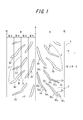
- FIG. 1 is a development plan view of a tire tread pattern showing an embodiment of a pneumatic tire for a motorcycle according to the present invention.
- FIG. 5 is a developed plan view of a tread pattern of a tire showing an embodiment of another pneumatic tire for a motorcycle according to the present invention.
- FIG. 6 is a development plan view of a tread pattern of a tire, showing another embodiment of a pneumatic tire for a motorcycle. It is a development top view of the tread pattern of the conventional tire. It is a development top view of the tread pattern of the conventional front-wheel tire.
- the pneumatic tire for a motorcycle according to the present invention is provided with a toroidal carcass that is connected to each other between the side portions via a side portion extending radially outward from the pair of bead portions, although not shown.
- a belt and a tread are provided on the outer side in the tire radial direction of the crown region of the carcass.
- FIG. 1 is a view showing an embodiment of a pneumatic tire for a motorcycle (hereinafter referred to as “tire”) according to the present invention.
- tire a pneumatic tire for a motorcycle (hereinafter referred to as “tire”) according to the present invention.
- 1 is a tread surface of the tire.
- an assembly 2 composed of three types of inclined lug grooves is arranged in one or more regions in the circumferential direction and the width direction of the tire in one region across the tire equator line e, while the other
- a single or a plurality of aggregates 2 arranged in a line symmetry with the tire equator line e as a symmetry axis are formed to form a tread pattern.
- the tread pattern as shown in FIG.
- the assembly 2 is arranged on one side of the tire equator line e with a predetermined pitch in the circumferential direction, and on the other side, the assembly 2 and An assembly 2 ′ having a line symmetric relationship across the equator line e is arranged at the same pitch as the assembly 2 and the arranged assembly 2 and assembly 2 ′ are shifted in the circumferential direction. (In the example shown, it may be shifted by a half pitch).
- a portion of the tread surface 1 other than the inclined lug groove is a land portion 3.
- the assembly 2 of inclined lug grooves includes a first inclined lug groove 2a, a second inclined lug groove 2b, and a third inclined lug groove 2c, and is arranged so as not to overlap each other.
- the inclined lug grooves 2a to 2c constituting the assembly 2 can be freely arranged in the width direction and the circumferential direction of the tire, and the order of arrangement is not specified.
- rear ends (rear ends with respect to the rotation direction) 2a 1 to 2c 1 of the inclined lugs 2a to 2c 1 are all located on the outer side in the width direction of the tread surface 1, and the tires are rotated forward from the rear end of the grooves.
- the direction (direction indicated by arrow C in FIG.
- the groove tips 2a 2 to 2c 2 are in the center of the tread.
- the convex portions 2a 3 to 2c 3 which are curved portions of the respective inclined lug grooves 2a to 2c are provided on an acute angle side among the angles formed by the respective inclined lug grooves and the tire equator line e.
- the angle formed between each of the inclined lug grooves 2a to 2c and the tire equator line e is the center line 2a 4 to 2c 4 passing through the center of each inclined lug groove in the width direction at the end 2a 2 to 2c 2 of the groove.
- the inclined lug grooves 2a ′ to 2c ′ arranged on the left side of the tire equator line e are symmetrical to the inclined lug grooves 2a to 2c due to the relationship between the aggregate 2 ′ and the aggregate 2. This is the same as the inclined lug grooves 2a to 2c except that the direction is opposite to the tire equator line e, and the same kind of lug grooves satisfying the characteristics of the inclined lug grooves 2a to 2c.
- each of the inclined lug grooves 2a to 2c has an extension length of the first inclined lug groove 2a as ⁇ , an extension length of the second inclined lug groove 2b as ⁇ , and a third inclined lug groove 2a-2c.
- the extension length of the lug groove 2c is ⁇
- the lengths ⁇ , ⁇ , and ⁇ satisfy the following formulas (I) and (II)
- the respective inclined lug grooves 2a to 2c When the number of intersections with respect to the meridian m of the tire is n, the number of intersections n shall satisfy the following formula (III).
- the extended lengths ⁇ , ⁇ , and ⁇ of the respective inclined lug grooves indicate the lengths of the respective inclined lug grooves at the positions of the center lines 2a 4 to 2c 4 .
- the tire meridian m is a line orthogonal to the tire equator line e, and the number of intersections n with respect to the tire meridian m is the tire meridian m in the development plan view of the tread pattern as shown in FIG.
- the range in which the number of inclined lug grooves intersecting with the meridian m of the tire is 4 or more is in the range of 60% to 70% with respect to the entire circumferential length of the tire. Means.
- each of the inclined lug grooves 2a to 2c according to the present invention the convex portions 2a 3 to 2c 3 face the same direction, and satisfy the above formulas (I) to (III). For this reason, even if the contact area of the tire is changed in the width direction of the tread surface according to the applied camber angle, the same type of groove exists in the contact area, and the change in the shape and ratio of the groove is small. The relationship between the drainage property and the grip property can be kept almost uniform with respect to the inclination. In addition, when the camber angle is given, the tire bends in the inclined direction, but each inclined lug groove 2a to 2c is bent in the tire equator line side along the forward rotation direction of the tire from the outer side in the width direction of the tire.
- the curved convex part is formed so as to face the center of the tire, the direction in which each inclined lug groove extends in the contact area changes according to the change of the camber angle. It will be along the direction in which the tire is moving, and the drainage can be improved. As a result, the sloped lug groove can be reduced by the amount of improved drainage, and the minimum necessary sloped lug groove for satisfying the drainage performance of the tire is ensured, but no unnecessary sloped lug groove is provided. Thus, the negative ratio can be lowered, and the grip property can be improved and the wear resistance can be improved.
- the tread pattern 1 corresponds to the tire equator when the length W from the tire equator line e to the tread ground contact TE is equally divided into one pitch in the circumferential direction in the development plan view of the tread pattern shown in FIG. It is more desirable that the difference between the negative ratio a of the second area A and the negative ratio b of the third area B counted from the line e is less than 0.01.
- the negative ratio refers to the ratio of the area occupied by the groove to the area of the tread surface divided in a predetermined range.
- the starting point for taking out one pitch in the circumferential direction may be from any groove of the assembly 2.
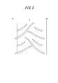
- FIG. 2 is a view showing a form of another pneumatic tire according to the present invention, and 1 in the figure shows a tread surface of the tire. Also in this case, a tread pattern having directionality is formed on the tread surface 1.
- the tread pattern here includes at least three types of inclined lug grooves 4 extending in the direction of convergence on the tire equator line e from each of the ground contact ends TE of the tread tread 1, and three types of inclined lug grooves 4a, inclined in the illustrated example. It has a lug groove 4b and an inclined lug groove 4c.
- the inclined lug groove extending in the direction of convergence from the tread grounding end TE to the tire equator line e means that one end of the inclined lug groove on the rear side in the tire rotation direction is the tread grounding end TE side, and the front side in the tire rotation direction. It says that the groove
- the direction converged on the tire equator line e means that it converges in a direction (a direction indicated by an arrow C in FIG. 2) that is a forward rotation direction of the tire.
- These three types of inclined lug grooves 4a to 4c are independently distributed in the tread half-width regions R and R ′ having the tire equator line e as a boundary so as not to cross each other.
- At least three types of inclined lug grooves are arranged symmetrically about the tire equator line e for each type, here for each of the inclined lug grooves 4a, 4b, 4c.
- the tread pattern is formed by shifting in the tire circumferential direction. More specifically, as shown in FIG.
- Each of the inclined lug grooves 4a, 4b, and 4c arranged in the half-width region R on the left side of the drawing with respect to e is so that the direction of each inclined lug groove with respect to the equator line e is opposite to the tire equator line e. This arrangement is shifted in the tire circumferential direction by a half pitch between the half-width regions R and R ′.
- the inclined lug groove 4a ′ corresponds to a shape in which the inclined lug groove 4a is reversed left and right
- the inclined lug groove 4b ′ corresponds to a shape in which the inclined lug groove 4b is reversed left and right
- the inclined lug groove 4c ′ is an inclined lug.
- each of the inclined lug grooves 4a to 4c and each of the inclined lug grooves 4a ′ to 4c ′ formed in the opposite half-width region are provided. Are assumed to be the same type of inclined lug grooves.
- the portion other than the portion where the inclined lug groove 4 is formed on the tread surface 1 is a land portion 3.
- each of the plurality of inclined lug grooves is formed in each half-width region extending in a direction converging from the tread ground contact end toward the tire equator line e.
- the slanted lug grooves are oriented in the same direction, so if the tire contact area changes in the tire width direction according to the camber angle applied, the same type of grooves are in the same contact area. Therefore, the same movement performance can be provided regardless of the amount of inclination of the tire.
- the inclined lug groove 4 a extending to the tire equator line e side (hereinafter referred to as “center inclined lug groove 4 a”) is 12.5 of the tread contact width TW from the tire equator line e. % In the central region K.
- the entire central inclined lug groove 4 a is disposed in the central region K.
- the center tilt lug grooves 4a it is important to extend in a direction angle theta 1 formed by the groove center line and the tire equator line e is in the range of 9 ° ⁇ 23 °.
- the groove center line here, passing through the central tilt lug grooves 4a, the tire width direction center P 1 in the tire forward direction tip, the tire width direction center P 2 in the tire forward direction rear end of the central inclined lug grooves Say a straight line.
- the extending length over the entire length of the central inclined lug groove 4a is 120 mm or less.
- the extending length over the entire length of the central inclined lug groove refers to the entire length of a line 4a 1 (line indicated by a one-dot chain line in FIG. 2) passing through the center of the central inclined lug groove in the tire width direction.
- the tread central region of the tire is mainly in contact with the road surface. For this reason, during the straight running of the tire, the land portion in the central region of the tread hits the road surface, and the repeated hitting sound of the land portion generates noise. Therefore, in the present invention, the angle ⁇ 1 formed between the central inclined lug groove 4a located in the central region K, which is most frequently in contact with the road surface when the tire is traveling straight, and the tire equator line e is 9 ° to 23 °. Is formed.
- the reason for this angle is that, from the viewpoint of drainage, the angle ⁇ 1 is increased to secure a drainage path from the tire equator line e side to the tread grounding end side at the rear of the tire rotation direction, and the ground contact with the tire. This is because it is necessary to cut a water film that enters between the road surface. Further, the inclination angle between the ground contact contour and the central inclined lug groove is close, so that the groove wall region when the tire is separated from the ground road surface is widened to suppress the generation of noise.
- the center tilt lug grooves 4a is the land portion 3 is the block-shaped in ground region oriented in the tire width direction, when ground with the road surface, and the trailing land portion at the time of 3 Will be amplified and noise will be amplified.
- the angle is less than 9 °, the drainage and the ability to cut the water film cannot be secured sufficiently.
- the central inclined lug groove 4a is restricted to the above groove angle, and the extension length over the entire length thereof is set to 120 mm or less to suppress a decrease in the rigidity of the land portion. Can be realized.
- the inclined lug grooves of the same shape (same type) arranged symmetrically with respect to the tire equator line e as the symmetry axis are provided by being shifted by a half pitch in the tire circumferential direction between the half width regions.
- the inclined lug groove of the same shape is simultaneously grounded from the road surface, and noise is not generated at the same time. That is, since land hitting sounds can be generated alternately with the tire equator line e as a boundary line, low noise performance can be improved.
- the central inclined lug groove 4a is arranged in the central region K without straddling the tire equator line e and has an inclination angle close to the tire circumferential direction, the rigidity of the land portion of the tire is increased, and the tire This improves the shear resistance applied in the direction of travel and the direction of retreat. Accordingly, it is possible to improve the wear resistance during traveling of an upright subject unique to a motorcycle (for example, a large scooter) and to suppress the occurrence of uneven wear.
- the central inclined lug groove 4a, the inclined lug groove 4b, and the inclined lug groove 4c are formed in order from the tire equator line e toward the tread grounding end TE. If the inclined lug groove 4a is formed closest to the tire equator line e, the other inclined lug grooves can be freely arranged in the width direction and the circumferential direction of the tire, and the regularity of the arrangement is not particularly relevant.
- the intermediate region L from the tire equator line e to 12.5% to 25% of the tread ground contact width TW at least two kinds of inclined lug grooves are arranged, and the tread from the tire equator line e is treaded.
- the intermediate region M of 25% to 37.5% of the ground contact width TW among the inclined lug grooves, the inclined lug grooves other than the central inclined lug groove 4a arranged closest to the tire equator line e are arranged. It is preferable.
- inclined lug grooves 4 b and 4 c are arranged in the intermediate region L and the intermediate region M.
- the camber angle is provided to the tire by arrange
- the drainage path which has sufficient groove width in a tread area And the water film that penetrates between the tire and the road surface can be cut by the edge effect of the groove, and the wet performance can be improved.
- the center P 2 in the tire width direction at the rear end portion of the central inclined lug groove does not extend to the intermediate region M, but the central region K or As will be described later, it is preferable to terminate in an intermediate region L from the tire equator line e to 12.5% to 25% of the tread contact width TW.
- the inclined lug grooves 4b and 4c, of the inclined lug grooves 4 are preferably in a shape having a bent portion 5 so that the tire equator line e side is the outer side of the bend.
- the central inclined lug groove 4a also has a curved shape that draws a gentle curve so that the tire equator line e side is the outside.
- the inclined lug groove disposed in the outer region in the tire width direction from the central region K into a shape bent so as to have a groove portion close to the tire width direction, the rigidity as the pattern can be ensured. As a result, it is possible to improve the grip performance.
- the inclined lug grooves 4b extends in the direction of the angle theta 2 formed by the circumferential groove center line and the tire equator line e is 20 ° ⁇ 35 °, the groove center in the width direction it is preferable that the angle theta 3 formed by lines and the tire equator line e extends in the direction to be 59 ° ⁇ 69 °.
- the circumferential direction of the groove center line to say, the middle point between the two intersections between the normal and the inclined lug grooves 4b of the bent portion 5 at the time of the Q 3, the tip of the tire forward direction of the inclined lug grooves 4b It refers to a straight line passing through the part Q 1 and the middle point Q 3.
- the groove center line in the width direction refers to a straight line passing through the rear end portion Q 2 and the middle point Q 3 of the tire forward direction of the inclined lug grooves 4b.
- the tip portion Q 1 and rear portion Q 2 of the inclined lug grooves has a tire width direction component
- the tip portion, the tire circumferential direction passing the widthwise center of the inclined lug grooves at the rear end portion the said center
- Q 1 and Q 2 be the midpoints of the lines connecting the intersections of the lines and the inclined lug grooves.
- the inclination lug groove 4c extends in a direction angle theta 4 formed by the circumferential groove center line and the tire equator line e is 29 ° ⁇ 41 °, formed by the groove center line and the tire equator line e in the width direction angle It is preferable that ⁇ 5 extends in the direction of 50 ° to 64 °.
- the tread pattern shown in the figure has a configuration in which a part of the central inclined lug groove 4a is arranged in an intermediate region L from the tire equator line e to 12.5% to 25% of the tread ground contact width TW.
- the rear end P 2 of the central inclined lug grooves 4a without terminating in the central area K, extends to the region L, which terminates in the intermediate region L.
- the center tilt lug grooves 4a are, within the central area K, extends in a direction angle theta 1 formed by the groove center line and the tire equator line e is 9 ° ⁇ 23 °, in the intermediate region L, the groove It is important that the angle ⁇ 6 formed by the center line and the tire equator line e extends in a direction that is 21 ° to 36 °.
- the groove center line in the central region K to say, a line 4a 1 through tire width direction center of the central inclined lug grooves 4a, when the intersection of the boundary of the central area K and the intermediate region L was P 3 to refers to a straight line connecting the tip P 1 and the intersection P 3 of the central inclined lug grooves 4a.
- the groove center line in the intermediate region L refers to a straight line connecting the rear end P 2 and the intersection P 3 of the central inclined lug grooves 4a.
- the generation of noise is caused by the land hitting sound at the time of ground contact in the central region K.
- the vibration sound at the time of kicking out the block is mainly deteriorated. Therefore, by maintaining the angles ⁇ 1 and ⁇ 6 at the above angles, the ground contact contour of the tire and the groove angle are kept away from each other, so that noise can be reduced.
- the reason why the angle ⁇ 6 is in the above range is that if the angle is less than 21 °, the angle of the groove approaches the grounding contour, and the length of the groove wall surface that oscillates away from the grounding surface on the kicking side increases, resulting in noise deterioration. This is because if the angle is larger than 36 °, the drainage performance of the ground contact edge portion decreases during traveling from a straight traveling to a small camber angle.
- each of the inclined lug grooves other than the central inclined lug groove 4a here, each of the inclined lug grooves 4b and 4c, has an opening area of 60% or more of the outermost outer side in the tire width direction of the central inclined lug groove 4a. It is preferable that it exists in the area
- each of the inclined lug grooves 4b and 4c disposed in the region outside the intermediate region L in the tire width direction has a central inclined lug of 60% or more of the opening area. tire width direction outermost end of the groove 4a, i.e.
- the opening area means the opening area in the tread surface 1.
- a tire satisfying the relationship shown in Table 1 and having a development plan view of the tread pattern shown in FIG. 1 and having a size of MCR160 / 60R15M / C is incorporated into a wheel having a rim size of MT5.00 and a filling air pressure of 250 kPa.
- the tire which becomes a development top view of the tread pattern shown in FIG. The front tire size was MCR120 / 70R15M / C, the rim size was MT3.50, and the filling air pressure was 225 kPa.
- the motorcycle was run on a test course, and the rear tire was examined for grip on wet roads, grip on dry roads, and tire wear resistance. Table 1 also shows the results including a conventional example (conventional tire 1) in which the tire having the pattern shown in FIG.
- the grip performance on the wet road surface and the grip performance on the dry road surface are determined as the grip performance by conducting the above-mentioned actual vehicle running test by a test rider and comprehensively determining the grip force change and the grip force change corresponding to the inclination of the tire, It was confirmed by feeling evaluation by a test rider.
- the results are shown in Table 1 as an index with the conventional tire 1 as a conventional example taken as 100. The larger the number, the higher the grip performance and the less the change in grip force with respect to the change in camber angle, and the better the drainage on wet road surfaces.
- the tire wear resistance was compared by observing the tire appearance after the above running test.
- the results are shown in Table 1 as an index with the conventional tire 1 as a conventional example taken as 100. Larger values indicate better wear resistance and longer wear life.
- the tires (comparative tires 1 and 2) in which the inclined lug grooves do not satisfy the above formulas (II) and (III) tend to be inferior in grip performance particularly on wet road surfaces, and cannot obtain sufficient performance.
- the above formulas (I) to (III) are satisfied, the difference between the negative ratios of regions A and B is less than 0.01, and the negative ratio in the range of W / 4 is set to the left and right across the tire equator line e. It was confirmed that the tires (compatible tires 1 and 2) made lower than the conventional tire 1 have high grip properties and excellent wear resistance.
- a tire with a size of MCR160 / 60R15M / C was prototyped according to the specifications shown in Table 2, and this tire was assembled into a wheel with a rim size of MT5.00 and filled. It was built into the rear wheel of a motorcycle, a large scooter with an air pressure of 250 kPa and a displacement of 500 cc. Moreover, the tire which becomes a development top view of the tread surface shown in FIG. The front tire size was MCR120 / 70R15M / C, the rim size was MT3.50, and the filling air pressure was 225 kPa.
- the motorcycle was run on a test course, and the tire noise level, the grip performance of the rear tire on the wet road surface, and the wear resistance of the tire were investigated. In addition, the noise was also evaluated with a bench test machine in order to strictly evaluate the tire performance.
- the tire conforming to the pattern of FIG. 2 is a conforming tire 3
- the tire having the pattern of FIG. 3 is a conforming tire 4
- the tire noise level was determined by calculating the overall value from the sound pressure waveform obtained from the actual vehicle measurement by the acceleration noise measurement method stipulated in the safety standards and the single measurement with the bench test machine.
- the result of each prototype tire is shown in Table 2 as an index, with the conventional tire 2 being a conventional example as 100. Larger numbers indicate less noise and lower noise levels.
- the actual vehicle is affected by the sound insulation (cowl, muffler, etc.) on the vehicle side used, the effect is 2% better, and the bench test has an effect of 10%.
- the grip performance on the wet road surface is determined by performing the above running test by a test rider, and judging the grip performance based on a comprehensive feeling evaluation of the grip force change corresponding to the magnitude of the grip force and the inclination of the tire. It was confirmed by feeling evaluation by the rider.
- the results are shown in Table 2 as an index with the conventional tire 2 as 100. The larger the number, the higher the grip performance, the less the change in grip force with respect to the change in camber angle, and the better the drainage.
- the tire wear resistance was compared by measuring the amount of tire wear after the above running test by depth gauge measurement.
- the results are shown in Table 2 as an index with the conventional tire 2 as a conventional example being taken as 100. It shows that it is excellent in abrasion resistance, so that this figure is large.
- both the conforming tire 3 and the conforming tire 4 had better noise level and better grip on the wet road surface and better wear resistance than the conventional tire 2.
- Tires (comparative tires 3 and 4) in which the angle of ⁇ 1 is outside the range of 9 ° to 23 ° are inferior in grip performance when the angle of ⁇ 1 is less than 9 ° compared to the conforming tire 3.
- the angle ⁇ 1 exceeds 23 °, the noise level and the grip performance on the wet road surface tend to be inferior.
- the central inclined lug groove exceeds 120 mm (comparative tire 5)
- the noise level and the wear resistance tend to be inferior as compared with the compatible tire 3.
- tire angle theta 6 is out of range of 21 ° ⁇ 36 ° (Comparative tire 6 and 7), compared to fit the tire 4, when the angle of theta 6 is less than 21 ° is the noise level It was found that when the angle ⁇ 6 exceeds 36 °, the grip performance on the wet road surface tends to be inferior.
Landscapes
- Engineering & Computer Science (AREA)
- Mechanical Engineering (AREA)
- Tires In General (AREA)
Priority Applications (5)
| Application Number | Priority Date | Filing Date | Title |
|---|---|---|---|
| US14/346,144 US20140216618A1 (en) | 2011-09-28 | 2011-09-28 | Pneumatic tire for an auto motorcycle |
| CN201180073787.9A CN103826871B (zh) | 2011-09-28 | 2011-09-28 | 机动两轮车用充气轮胎 |
| JP2013535633A JP5927196B2 (ja) | 2011-09-28 | 2011-09-28 | 自動二輪車用空気入りタイヤ |
| PCT/JP2011/005470 WO2013046266A1 (ja) | 2011-09-28 | 2011-09-28 | 自動二輪車用空気入りタイヤ |
| EP11873022.5A EP2762332B1 (en) | 2011-09-28 | 2011-09-28 | Pneumatic tire for an auto motorcycle |
Applications Claiming Priority (1)
| Application Number | Priority Date | Filing Date | Title |
|---|---|---|---|
| PCT/JP2011/005470 WO2013046266A1 (ja) | 2011-09-28 | 2011-09-28 | 自動二輪車用空気入りタイヤ |
Publications (1)
| Publication Number | Publication Date |
|---|---|
| WO2013046266A1 true WO2013046266A1 (ja) | 2013-04-04 |
Family
ID=47994392
Family Applications (1)
| Application Number | Title | Priority Date | Filing Date |
|---|---|---|---|
| PCT/JP2011/005470 WO2013046266A1 (ja) | 2011-09-28 | 2011-09-28 | 自動二輪車用空気入りタイヤ |
Country Status (5)
| Country | Link |
|---|---|
| US (1) | US20140216618A1 (zh) |
| EP (1) | EP2762332B1 (zh) |
| JP (1) | JP5927196B2 (zh) |
| CN (1) | CN103826871B (zh) |
| WO (1) | WO2013046266A1 (zh) |
Cited By (2)
| Publication number | Priority date | Publication date | Assignee | Title |
|---|---|---|---|---|
| JP2013193518A (ja) * | 2012-03-16 | 2013-09-30 | Sumitomo Rubber Ind Ltd | 自動二輪車用タイヤ |
| JP2015024796A (ja) * | 2013-07-29 | 2015-02-05 | 住友ゴム工業株式会社 | 自動二輪車用タイヤ |
Families Citing this family (7)
| Publication number | Priority date | Publication date | Assignee | Title |
|---|---|---|---|---|
| DE202013003767U1 (de) * | 2013-04-20 | 2013-05-15 | GM Global Technology Operations LLC (n. d. Ges. d. Staates Delaware) | Kraftfahrzeug mit Fahrbahnbeurteilungseinrichtung |
| CN106166924B (zh) * | 2016-08-26 | 2023-10-27 | 四川远星橡胶有限责任公司 | 一种摩托车用轮胎 |
| JP6850695B2 (ja) * | 2017-07-14 | 2021-03-31 | 株式会社ブリヂストン | 自動二輪車用空気入りタイヤ |
| JP7062012B2 (ja) * | 2017-10-11 | 2022-05-02 | 株式会社ブリヂストン | 自動二輪車用タイヤ |
| JP6850712B2 (ja) * | 2017-10-11 | 2021-03-31 | 株式会社ブリヂストン | 自動二輪車用タイヤ |
| CN108891204A (zh) * | 2018-07-25 | 2018-11-27 | 建大橡胶(中国)有限公司 | 钢丝结构防爆摩托车轮胎 |
| JP7126968B2 (ja) * | 2019-03-01 | 2022-08-29 | 株式会社ブリヂストン | 二輪車用タイヤ |
Citations (6)
| Publication number | Priority date | Publication date | Assignee | Title |
|---|---|---|---|---|
| JPH04238703A (ja) | 1991-01-10 | 1992-08-26 | Sumitomo Rubber Ind Ltd | 空気入りタイヤ |
| JP2006321287A (ja) * | 2005-05-17 | 2006-11-30 | Bridgestone Corp | 自動二輪車用空気入りラジアルタイヤ |
| JP2007331596A (ja) * | 2006-06-15 | 2007-12-27 | Bridgestone Corp | 自動二輪車用タイヤ |
| JP2009029176A (ja) * | 2007-07-24 | 2009-02-12 | Bridgestone Corp | 自動二輪車用空気入りタイヤ |
| WO2010073279A1 (en) * | 2008-12-24 | 2010-07-01 | Pirelli Tyre S.P.A. | Tyre for motor vehicles |
| WO2011118186A1 (ja) * | 2010-03-26 | 2011-09-29 | 株式会社ブリヂストン | 自動二輪車用空気入りタイヤ |
Family Cites Families (6)
| Publication number | Priority date | Publication date | Assignee | Title |
|---|---|---|---|---|
| JP2003211917A (ja) * | 2002-01-18 | 2003-07-30 | Bridgestone Corp | 二輪車用空気入りタイヤ |
| JP4431167B2 (ja) * | 2007-10-22 | 2010-03-10 | 住友ゴム工業株式会社 | 空気入りタイヤ |
| BRPI0823307B1 (pt) * | 2008-12-24 | 2020-01-28 | Pirelli | pneu para veículos a motor, par de pneus para veículos a motor, e, método para indicação de possibilidade de usar veículo a motor com os pneus que alcançaram condições de uso ideais ao condutor de um veículo a motor |
| JP5351627B2 (ja) * | 2009-06-12 | 2013-11-27 | 住友ゴム工業株式会社 | 自動二輪車用タイヤ |
| JP5506353B2 (ja) * | 2009-12-04 | 2014-05-28 | 株式会社ブリヂストン | 自動二輪車用空気入りタイヤ |
| USD644166S1 (en) * | 2010-09-27 | 2011-08-30 | Bridgestone Corporation | Motorcycle tire |
-
2011
- 2011-09-28 EP EP11873022.5A patent/EP2762332B1/en not_active Not-in-force
- 2011-09-28 CN CN201180073787.9A patent/CN103826871B/zh not_active Expired - Fee Related
- 2011-09-28 JP JP2013535633A patent/JP5927196B2/ja not_active Expired - Fee Related
- 2011-09-28 US US14/346,144 patent/US20140216618A1/en not_active Abandoned
- 2011-09-28 WO PCT/JP2011/005470 patent/WO2013046266A1/ja active Application Filing
Patent Citations (6)
| Publication number | Priority date | Publication date | Assignee | Title |
|---|---|---|---|---|
| JPH04238703A (ja) | 1991-01-10 | 1992-08-26 | Sumitomo Rubber Ind Ltd | 空気入りタイヤ |
| JP2006321287A (ja) * | 2005-05-17 | 2006-11-30 | Bridgestone Corp | 自動二輪車用空気入りラジアルタイヤ |
| JP2007331596A (ja) * | 2006-06-15 | 2007-12-27 | Bridgestone Corp | 自動二輪車用タイヤ |
| JP2009029176A (ja) * | 2007-07-24 | 2009-02-12 | Bridgestone Corp | 自動二輪車用空気入りタイヤ |
| WO2010073279A1 (en) * | 2008-12-24 | 2010-07-01 | Pirelli Tyre S.P.A. | Tyre for motor vehicles |
| WO2011118186A1 (ja) * | 2010-03-26 | 2011-09-29 | 株式会社ブリヂストン | 自動二輪車用空気入りタイヤ |
Non-Patent Citations (1)
| Title |
|---|
| See also references of EP2762332A4 * |
Cited By (5)
| Publication number | Priority date | Publication date | Assignee | Title |
|---|---|---|---|---|
| JP2013193518A (ja) * | 2012-03-16 | 2013-09-30 | Sumitomo Rubber Ind Ltd | 自動二輪車用タイヤ |
| JP2015024796A (ja) * | 2013-07-29 | 2015-02-05 | 住友ゴム工業株式会社 | 自動二輪車用タイヤ |
| WO2015015988A1 (ja) * | 2013-07-29 | 2015-02-05 | 住友ゴム工業株式会社 | 自動二輪車用タイヤ |
| CN105377586A (zh) * | 2013-07-29 | 2016-03-02 | 住友橡胶工业株式会社 | 摩托车用轮胎 |
| US10071600B2 (en) | 2013-07-29 | 2018-09-11 | Sumitomo Rubber Industries, Ltd. | Tire for motorbike |
Also Published As
| Publication number | Publication date |
|---|---|
| CN103826871A (zh) | 2014-05-28 |
| CN103826871B (zh) | 2016-12-07 |
| JP5927196B2 (ja) | 2016-06-01 |
| US20140216618A1 (en) | 2014-08-07 |
| EP2762332A1 (en) | 2014-08-06 |
| JPWO2013046266A1 (ja) | 2015-03-26 |
| EP2762332B1 (en) | 2017-03-08 |
| EP2762332A4 (en) | 2015-07-22 |
Similar Documents
| Publication | Publication Date | Title |
|---|---|---|
| JP5927196B2 (ja) | 自動二輪車用空気入りタイヤ | |
| WO2011118186A1 (ja) | 自動二輪車用空気入りタイヤ | |
| JP5667614B2 (ja) | 空気入りタイヤ | |
| WO2017122742A1 (ja) | 空気入りタイヤ | |
| EP1372988B1 (en) | Tread pattern for car tire | |
| US10207545B2 (en) | Pneumatic tire | |
| JP5827663B2 (ja) | 不整地走行用の自動二輪車用タイヤ | |
| JP6125142B2 (ja) | 空気入りタイヤ | |
| WO2006123480A1 (ja) | 自動二輪車用空気入りラジアルタイヤ | |
| JP7251219B2 (ja) | タイヤ | |
| JP5596580B2 (ja) | 自動二輪車用空気入りタイヤ | |
| JPS585803B2 (ja) | 低騒音ラグタイヤ | |
| JP2020142587A (ja) | タイヤ | |
| JP2012162160A (ja) | 自動二輪車用空気入りタイヤ | |
| JP5965138B2 (ja) | 自動二輪車用空気入りタイヤ | |
| JP5517319B1 (ja) | 自動二輪車用タイヤ | |
| JP5497813B2 (ja) | 自動二輪車用空気入りタイヤ | |
| JP5426447B2 (ja) | 二輪車用空気入りタイヤ | |
| JP5890192B2 (ja) | 自動二輪車用空気入りタイヤ | |
| JP6082367B2 (ja) | 空気入りタイヤ | |
| JP6060217B2 (ja) | 自動二輪車用空気入りタイヤ | |
| JP2016141226A (ja) | 自動二輪車用空気入りタイヤ | |
| JP5804697B2 (ja) | 自動二輪車用空気入りタイヤ | |
| JP7131358B2 (ja) | 空気入りラジアルタイヤ | |
| JP2007106167A (ja) | 空気入りタイヤ |
Legal Events
| Date | Code | Title | Description |
|---|---|---|---|
| 121 | Ep: the epo has been informed by wipo that ep was designated in this application |
Ref document number: 11873022 Country of ref document: EP Kind code of ref document: A1 |
|
| ENP | Entry into the national phase |
Ref document number: 2013535633 Country of ref document: JP Kind code of ref document: A |
|
| REEP | Request for entry into the european phase |
Ref document number: 2011873022 Country of ref document: EP |
|
| WWE | Wipo information: entry into national phase |
Ref document number: 2011873022 Country of ref document: EP |
|
| NENP | Non-entry into the national phase |
Ref country code: DE |
|
| WWE | Wipo information: entry into national phase |
Ref document number: 14346144 Country of ref document: US |