EP2762332B1 - Pneumatic tire for an auto motorcycle - Google Patents
Pneumatic tire for an auto motorcycle Download PDFInfo
- Publication number
- EP2762332B1 EP2762332B1 EP11873022.5A EP11873022A EP2762332B1 EP 2762332 B1 EP2762332 B1 EP 2762332B1 EP 11873022 A EP11873022 A EP 11873022A EP 2762332 B1 EP2762332 B1 EP 2762332B1
- Authority
- EP
- European Patent Office
- Prior art keywords
- tire
- oblique lug
- tread
- grooves
- equator line
- Prior art date
- Legal status (The legal status is an assumption and is not a legal conclusion. Google has not performed a legal analysis and makes no representation as to the accuracy of the status listed.)
- Not-in-force
Links
Images


Classifications
-
- B—PERFORMING OPERATIONS; TRANSPORTING
- B60—VEHICLES IN GENERAL
- B60C—VEHICLE TYRES; TYRE INFLATION; TYRE CHANGING; CONNECTING VALVES TO INFLATABLE ELASTIC BODIES IN GENERAL; DEVICES OR ARRANGEMENTS RELATED TO TYRES
- B60C11/00—Tyre tread bands; Tread patterns; Anti-skid inserts
- B60C11/03—Tread patterns
- B60C11/0302—Tread patterns directional pattern, i.e. with main rolling direction
-
- B—PERFORMING OPERATIONS; TRANSPORTING
- B60—VEHICLES IN GENERAL
- B60C—VEHICLE TYRES; TYRE INFLATION; TYRE CHANGING; CONNECTING VALVES TO INFLATABLE ELASTIC BODIES IN GENERAL; DEVICES OR ARRANGEMENTS RELATED TO TYRES
- B60C11/00—Tyre tread bands; Tread patterns; Anti-skid inserts
- B60C11/03—Tread patterns
- B60C11/0304—Asymmetric patterns
-
- B—PERFORMING OPERATIONS; TRANSPORTING
- B60—VEHICLES IN GENERAL
- B60C—VEHICLE TYRES; TYRE INFLATION; TYRE CHANGING; CONNECTING VALVES TO INFLATABLE ELASTIC BODIES IN GENERAL; DEVICES OR ARRANGEMENTS RELATED TO TYRES
- B60C11/00—Tyre tread bands; Tread patterns; Anti-skid inserts
- B60C11/03—Tread patterns
- B60C11/0327—Tread patterns characterised by special properties of the tread pattern
- B60C11/033—Tread patterns characterised by special properties of the tread pattern by the void or net-to-gross ratios of the patterns
-
- B—PERFORMING OPERATIONS; TRANSPORTING
- B60—VEHICLES IN GENERAL
- B60C—VEHICLE TYRES; TYRE INFLATION; TYRE CHANGING; CONNECTING VALVES TO INFLATABLE ELASTIC BODIES IN GENERAL; DEVICES OR ARRANGEMENTS RELATED TO TYRES
- B60C11/00—Tyre tread bands; Tread patterns; Anti-skid inserts
- B60C11/03—Tread patterns
- B60C2011/0337—Tread patterns characterised by particular design features of the pattern
- B60C2011/0339—Grooves
- B60C2011/0374—Slant grooves, i.e. having an angle of about 5 to 35 degrees to the equatorial plane
-
- B—PERFORMING OPERATIONS; TRANSPORTING
- B60—VEHICLES IN GENERAL
- B60C—VEHICLE TYRES; TYRE INFLATION; TYRE CHANGING; CONNECTING VALVES TO INFLATABLE ELASTIC BODIES IN GENERAL; DEVICES OR ARRANGEMENTS RELATED TO TYRES
- B60C11/00—Tyre tread bands; Tread patterns; Anti-skid inserts
- B60C11/03—Tread patterns
- B60C2011/0337—Tread patterns characterised by particular design features of the pattern
- B60C2011/0339—Grooves
- B60C2011/0381—Blind or isolated grooves
- B60C2011/0383—Blind or isolated grooves at the centre of the tread
-
- B—PERFORMING OPERATIONS; TRANSPORTING
- B60—VEHICLES IN GENERAL
- B60C—VEHICLE TYRES; TYRE INFLATION; TYRE CHANGING; CONNECTING VALVES TO INFLATABLE ELASTIC BODIES IN GENERAL; DEVICES OR ARRANGEMENTS RELATED TO TYRES
- B60C2200/00—Tyres specially adapted for particular applications
- B60C2200/10—Tyres specially adapted for particular applications for motorcycles, scooters or the like
Definitions
- the present invention relates to a pneumatic tire for an auto motorcycle, in particular, proposes a technology capable of improving grip performance against a dry road while ensuring drainage performance during running on a wet road, and also capable of attaining excellent wear resistance.
- various tread patterns are formed by changing, in multiple ways, combinations of the number and the shapes of grooves formed on a tread portion of the tire, to thereby improve various performances (such as drainage performance under wet condition and noise reduction during running) (see, for example, JP H4-238703 A (PTL 1)).
- Document JP 2010-285103 A discloses a pneumatic tire for motorcycle comprising the features of the preamble of claim 1.
- the groove portion in the tread portion is decreased in ratio, which makes it difficult to maintain drainage performance.
- One of the main objects of the present invention is to provide a pneumatic tire excellent in wear resistance while being improved in grip performance against a dry road, without impairing drainage performance of the tire in running on a wet road.
- another object of the present invention is to provide a novel pneumatic tire for an auto motorcycle which is capable of reducing noise during running, in addition to ensuring the aforementioned various kinds of performance.
- the present invention provides a pneumatic tire for an auto motorcycle, having a directional tread pattern including a plurality of different grooves formed on a tread surface, the grooves each converging forward in a rotation direction of the tire, in which:
- the present invention provides a pneumatic tire for an auto motorcycle, including a tread pattern having at least three different oblique lug grooves formed on a tread surface of the tire, the grooves each extending as converging forward in the rotation direction of the tire from a contact end side to a tire equator line side, the tread surface including half-width regions across the tire equator line serving as a boundary, the at least three different oblique lug grooves being independently disposed while being dispersed in each of the half-width regions, the at least three different oblique lug grooves being arranged so as to be line-symmetric, for each type, about the tire equator line as an axis of symmetry while being displaced from each other in the tire circumferential direction between the half-width regions, in which the at least three oblique lug grooves includes a central oblique lug groove disposed in a center region which accounts for an area of 12.5 % of the tread contact width from the tire equator line
- At least three different oblique lug grooves at least two different oblique lug grooves be disposed in the intermediate region falling within a range of 12.5 % to 25 % of the tread contact width from the tire equator line; and that, of the at least three different oblique lug grooves, at least an oblique lug groove other than the central oblique lug groove be disposed in an intermediate region falling within a range of 25 % to 37.5 % of the tread contact width from the tire equator line.
- At least two different oblique lug grooves other than the central oblique lug groove be curved so that the outside of the curve is directed toward the tire equator line side.
- the oblique lug grooves other than the central oblique lug groove be each disposed, by 60 % or more of the opening area thereof, in a region on the outside in the tire width direction of the outermost end of the central oblique lug groove in the tire width direction of the central oblique lug groove.
- the tread width from the tire equator line to the tread contact end is equally divided into quarters so as to form four regions for one pitch in the circumferential direction of the tread surface, and a second region A and a third region B of the four regions from the tire equator line are different from each other in negative ratio by less than 0.01, the area of the land portion in the contact area hardly changes regardless of the change in camber angle, so that the grip performance can be maintained further uniform.
- another pneumatic tire of the present invention includes a tread pattern including at least three different oblique lug grooves formed on a tread surface of the tire, the grooves each extending as converging forward in the rotation direction of the tire from a contact end side to a tire equator line side, the tread surface including half-width regions across the tire equator line serving as a boundary, the at least three different oblique lug grooves being independently disposed while being dispersed in each of the half-width regions, the at least three different oblique lug grooves being arranged so as to be line-symmetric, for each type, about the tire equator line as an axis of symmetry while being displaced from each other in the tire circumferential direction between the half-width regions, in which the at least three oblique lug grooves includes a central oblique lug groove disposed in a center region which accounts for an area of 12.5 % of the tread contact width from the tire equator line, the central o
- the pneumatic tire for an auto motorcycle according to the present invention includes, although not shown, toroidal carcasses disposed through side portions extending outwardly in a radial direction from a pair of bead portions, so as to be mutually connected across the side portions, and also includes a belt and a tread on the outside in the tire radial direction of the crown region of the carcasses.
- FIG. 1 illustrates an embodiment of a pneumatic tire for an auto motorcycle (hereinafter, referred to as "tire") according to the present invention, in which a tread surface 1 of the tire is shown.
- the tread surface 1 is divided into two regions across a tire equator line e, and one or a plurality of sets 2 of three different oblique lug grooves are arranged in each of the two regions in the tire circumferential direction and in the tire width direction, so as to be line-symmetric to each other about the tire equator line e serving as the axis of symmetry, to thereby form a tread pattern.
- the tread pattern may also be formed, as illustrated in FIG.
- the sets 2 of the oblique lug grooves each include a first incline lug groove 2a, a second oblique lug groove 2b, and a third oblique lug groove 2c, which are disposed without overlapping one another.
- the oblique lug grooves 2a to 2c forming the respective sets 2 can be freely arranged in the tire width direction and circumferential direction, with no limitations on the arrangement order thereof.
- the oblique lug grooves 2a to 2c all have posterior ends (trailing end relative to the rotation direction) 2a 1 to 2c 1 disposed on the outside in the width direction of the tread surface 1, and extend, from the posterior ends of the grooves, along a direction (direction indicated by an arrow C of FIG.
- the oblique lug grooves 2a to 2c are each configured to satisfy the following Expressions (I), (II): ⁇ (I), 1- ⁇ / ⁇ 0.1 (II), where ⁇ is the extending length of the first oblique lug groove 2a, ⁇ is the extending length of the second oblique lug groove 2b, and ⁇ is the extending length of the third oblique lug groove 2c, and also the number n of the oblique lug grooves 2a to 2c each intersecting with a meridian m of the tire is defined to satisfy the following Expression (III): n ⁇ 4 (III) (where the oblique lug grooves are assumed to be disposed within a range of 60 % to 70 % of the entire circumference of the tire).
- the oblique lug grooves 2a to 2c according to the present invention each have the convex portions 2a 3 to 2c 3 , respectively, which are oriented in the same direction while satisfying the aforementioned Expressions (I) to (III). Accordingly, even when the contact area of the tire is varied in the width direction of the tread surface in accordance with a camber angle applied thereto, grooves of the same type are still present in the contact area with being hardly changed in shape or ratio of the grooves, to thereby maintain substantially uniform the relation between the drainage performance and the grip performance relative to the tilt of the tire.
- the number of oblique lug grooves can be reduced accordingly, so as to secure the minimum number of oblique lug grooves required to satisfy the drainage performance of the tire while saving unnecessary oblique lug grooves, to thereby reduce the negative ratio, with the result that the wear resistance as well as the grip performance can be improved.
- a second region A and a third region B from the tire equator line e have a negative ratio a and a negative ratio b, respectively, the negative ratio a and the negative ratio b being different from each other by less than 0.01.
- the negative ratio herein refers to a ratio of an area occupied by grooves to an area of a tread surface defined by a predetermined range.
- the starting point to take out one pitch in the circumferential direction may be any of the grooves in the set 2.
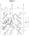
- FIG. 2 illustrates an embodiment of another pneumatic tire according to the present invention, in which a tread surface 1 of the tire is shown. Similarly to the above, the tread surface 1 has a directional tread pattern formed thereon.
- the tread pattern herein includes at least three different oblique lug grooves 4, including, in the illustrated example, three different oblique lug grooves, namely, an oblique lug groove 4a, an oblique lug groove 4b, and an oblique lug groove 4c, each extending, from each of both contact ends TE of the tread surface 1, in a direction converging to the tire equator line e .
- These three different oblique lug grooves 4a to 4c are independently arranged as being dispersed in tread half-width regions R, R' across the tire equator line e as a border therebetween, without intersecting with one another.
- the at least three different oblique lug grooves are arranged so as to be line-symmetric, for each type, namely, for each of the oblique lug grooves 4a, 4b, and 4c in this case, about the tire equator line e serving as the axis of symmetry.
- the oblique lug grooves thus arranged are displaced from each other in the tire circumferential direction between the half-width regions R, R', to thereby form a tread pattern. More specifically, as illustrated in FIG.
- the oblique lug grooves 4a', 4b', 4c' disposed in the half-width region R' on the right in the paper plane across the tire equator line e are each arranged in a direction opposite to the oblique lug grooves 4a, 4b, 4c disposed in the half-width region R on the left in the paper plane across the tire equator line e , and the oblique lug grooves 4a, 4b, 4c and the oblique lug grooves 4a', 4b', 4c' thus arranged are shifted from each other by half the pitch in the tire circumferential direction between the half-width regions R and R'.
- the oblique lug groove 4a' corresponds to a horizontally-reversed shape of the oblique lug groove 4a
- the oblique lug groove 4b' corresponds to a horizontally-reversed shape of the oblique lug groove 4b
- the oblique lug groove 4c' corresponds to a horizontally-reversed shape of the oblique lug groove 4c
- the oblique lug grooves 4a to 4c each are the same type of each of the oblique lug grooves 4a' to 4c' formed in the half-width region on the opposite side.
- the remaining portion of the tread surface 1, other than the portions where the oblique lug grooves 4 are formed, is formed as the land portion 3.
- the oblique lug groove 4a (hereinafter, referred to as "central oblique lug groove 4a") extending closest to the tire equator line e side is disposed in a central region K which accounts for an area of 12.5 % of the tread contact width TW from the tire equator line e.
- the central oblique lug groove 4a is disposed as a whole within the central region K .
- the central oblique lug groove 4a extend in a direction that allows an angle ⁇ 1 between a groove center line thereof and the tire equator line e to fall within a range of 9° to 23°.
- the groove center line refers to a straight line passing through a tire width direction center P 1 of the central oblique lug groove 4a at the anterior end portion in the tire advancement direction and a tire width direction center P 2 of the central oblique lug groove at the posterior end portion in the tire advancement direction.
- the central oblique lug groove 4a be formed to have an extending length of 120 mm or less over the entire length thereof.
- the extending length over the entire length of the central oblique lug groove 4a refers to an entire length of a line 4a 1 (line rendered as the alternate long and short dash line in FIG. 2 ) passing through the center in the tire width direction of the central oblique lug groove.
- the tread center region of the tire mainly comes into contact with a road surface when the vehicle is running straight because the vehicle stands substantially upright with respect to a road surface. Therefore, the land portion of the tread center region hits the road surface when the tire is running straight, and the repeated hit sound of the land portion leads to generation of noise.
- the central oblique lug groove 4a positioned within the central region K which most often comes into contact with a road surface when the tire is running straight, is formed to be at an angle ⁇ 1 of 9° to 23° with the tire equator line e .
- the reason for defining the angle ⁇ 1 as described above is that the angle ⁇ 1 should be large enough to ensure a drainage path from the tire equator line e side to the tread contact end side located backward in the tire rotation direction while breaking a water film that enters between the tire and the contact road.
- the oblique angle of the central oblique lug groove approximates the contact contour of the tire, a larger groove wall region can be ensured when the tire comes out of contact with the contact road, to thereby suppress generation of noise.
- the angle ⁇ 1 is larger than 23°, the central oblique lug groove 4a is directed toward the tire width direction so that the land portion 3 within the contact area is formed in a block shape, with the result that the land portion 3 is excited when the tire comes into contact with a road surface and is kicked out therefrom, leading to amplification of noise.
- the tangle ⁇ 1 smaller than 9° fails to sufficiently ensure the drainage performance and the capability of breaking a water film.
- the oblique lug grooves in the same shape are symmetrically arranged about the tire equator line e as the axis of symmetry, and the oblique lug grooves formed in the half width regions across the tire equator line e are mutually displaced by half the pitch in the tire circumferential direction, to thereby prevent the oblique lug grooves in the same shape from simultaneously coming into contact with a road surface to generate noise at the same time. That is, the land portions on both sides across the tire equator line e as a boundary generate hit sound alternately, to thereby improve low noise performance.
- the central oblique lug groove 4a is disposed within the central region K without crossing the tire equator line e , at an inclination angle close to the tire circumferential direction, with the result that the land portion of the tire is increased in rigidity, to thereby improve the shear strength against a load applied in the forward direction and the backward direction of the tire. Therefore, the tire can be improved in wear resistance in running in the upright position which is unique to an auto motorcycle (such as a large motor scooter), so as to suppress generation of partial wear.
- the central oblique lug groove 4a, the oblique lug groove 4b, and the oblique lug groove 4c are formed in order from the tire equator line e to the tread contact end TE.
- the oblique lug groove 4b and the oblique lug groove 4c may be freely disposed in the tire width direction and in the tire circumferential direction without any specific arrangement regularities, as long as the aforementioned central oblique lug groove 4a is disposed closest to the tire equator line e side.
- At least two different oblique lug grooves of the oblique lug grooves may preferably be disposed in an intermediate region L falling within a range of 12.5 % to 25 % of the tread contact width TW from the tire equator line e.
- oblique lug grooves other than the central oblique lug groove 4a disposed closest to the tire equator line e side may preferably be disposed in an intermediate region M falling within a range of 25 % to 37.5 % of the tread contact width TW from the tire equator line e.
- the oblique lug grooves 4b and 4c are disposed in the intermediate region L and the intermediate region M.
- the oblique lug grooves are disposed even in the intermediate region L and in the intermediate region M , so that even when a camber angle is applied to the tire and a water film entering between the tire, a drainage path having a sufficient groove width in the tread region can be ensured and a water film entering between the tire and the contact road can be broken due to the edge effect of the grooves, to thereby improve wet performance.
- the tire width direction center P 2 at the posterior end of the central oblique lug groove may preferably be terminated within the central region K or within the intermediate region L falling within the range of 12.5 % to 25 % of the tread contact width TW from the tire equator line e as described later, without extending to the intermediate region M .
- At least two different oblique lug grooves of the oblique lug grooves 4, namely, the oblique lug grooves 4b and 4c in this case, may preferably be in a shape having a curved portion 5 which is curved outward toward the tire equator line e side.
- the central oblique lug groove 4a is also formed in a curved shape curved outward with a gentle curvature toward the tire equator line e side.
- the oblique lug groove 4b may preferably extend in a direction where the groove center line in the circumferential direction is at an angle ⁇ 2 of 20° to 35° with the tire equator line e and extend in a direction where the groove center line in the width direction is at an angle ⁇ 3 of 59° to 69° with the tire equator line e .
- the groove center line in the circumferential direction refers to a straight line passing through the leading end portion Q 1 and a midpoint Q 3 in the tire advancement direction, the midpoint Q 3 being a midpoint between two points where the normal of the curved portion 5 intersects with the oblique lug groove 4b.
- the groove center line in the width direction refers to a line passing through the trailing end portion Q 2 of the oblique lug groove 4b in the tire advancement direction and the aforementioned midpoint Q 3 .
- Q 1 and Q 2 are each defined as a midpoint of a line connecting the center in the width direction of the oblique lug groove at the anterior end portion or at the posterior end portion and an intersection point between a line in the tire circumferential direction passing through the center and the oblique lug groove.
- the oblique lug groove 4c may preferably extend in a direction where the groove center line in the circumferential direction is at an angle ⁇ 4 of 29° to 41° with the tire equator line e , and extend in a direction where the groove center line in the width direction is at an angle ⁇ 5 of 50° to 64° with the tire equator line e.
- the groove center line in the central region K is defined herein as a straight line connecting between an anterior end P 1 of the central oblique lug groove 4a and an intersection point P 3 , the intersection point P 3 being an intersection point where the line 4a 1 passing through the center of the central oblique lug groove 4a in the tire width direction intersects with a boundary between the central region K and the intermediate region L.
- the groove center line in the intermediate region L refers to a straight line connecting between the posterior end P 2 of the central oblique lug groove 4a and the intersection point P 3 .
- the angle ⁇ 6 when the angle ⁇ 6 is smaller than 21°, the angle of the groove approximates the contact contour so that the groove wall surface is vibrated along a longer length when coming out of contact with the contact surface on the kick-out side, resulting in an increase in noise.
- the angle ⁇ 6 is larger than 36°, the drainage performance on the contact end portion is degraded in running straight or at a small camber angle.
- the oblique lug grooves other than the central oblique lug groove 4a namely, the oblique lug grooves 4b and 4c herein, be each disposed, by 60 % or more of the opening area thereof, in a region on the outside in the tire width direction of the outermost end of the central oblique lug groove 4a in the tire width direction.
- the oblique lug grooves 4b and 4c disposed in a region on the outside in the tire width direction of the intermediate region L are each disposed, by 60 % or more of the opening area thereof, in a region falling within a range between a straight line parallel to the equator line e while passing through the outermost end side in the tire width direction of the central oblique lug groove 4a, that is, the posterior end P 2 of the central oblique lug groove 4a, and 50 % of the tread contact width.
- the opening area refers to an opening area on the tread surface 1.
- a plurality of oblique lug grooves are evenly disposed across the entire region of the tread surface 1, so that the same type of grooves are arranged in the same contact area even when the contact area of the tire has been changed in the tire width direction according to a camber angle applied thereto, to thereby provide the same motion performance irrespective of the inclination of the tire.
- FIG. 1 including a conventional example (Conventional Tire 1) where the tire having a pattern illustrated in FIG. 4 was assembled to the rear tire.
- FIG. 4 Conventional Tire 1 Conforming Tire 1 Conforming Tire 2 Comparative Tire 1 Comparative Tire 2 Tread pattern
- FIG. 4 Conventional shape
- tires with oblique lug grooves that do not satisfy the aforementioned Expressions (II), (III) (Comparative Tire 1, 2) are apt to be inferior in grip performance, particularly on a wet road, failing to attain sufficient performance.
- tires which satisfy the aforementioned Expressions (I) to (III) with a difference in negative ratio between the regions A and B being less than 0.01, and have a negative ratio in a range of W /4 on the right and left across the tire equator line e that is lower than the conventional tire 1 (Conforming Tires 1, 2) were all high in grip performance and excellent in wear resistance.
- a tire in a size of MCR160/60R15M/C was manufactured as a sample under the specifications shown in Table 2. Then, this tire was assembled to a wheel with a rim size of MT5.00, and used as a rear tire of an auto motorcycle of 500 cc displacement at a filling air pressure of 250 kPa.
- a tire having a tread pattern illustrated in the development plan view of FIG. 5 as a conventional product was assembled for use as a front tire. The front tire was in a size of MCR120/70R15M/C, with a rim size of MT3.50, at a filling air pressure of 225 kPa.
- the noise levels of the tires were determined by subjecting a real vehicle to acceleration noise measurement set forth in the safety standards and by calculating an overall value from a sound pressure waveform obtained in the stand-alone measurement of the tire in the bench test machine.
- Table 2 shows the measurement results obtained for the sample tires as index values with a score of 100 representing Conventional Tire 2 as a conventional example. The larger number indicates a lower noise level with reduced noise.
- the noise level was improved by 2 % under the influence of the sound insulation (attained by, for example, a cowl muffler) on the used vehicle side, whereas the noise level was improved by 10 % in the measurement by the bench test machine.
- Table 2 shows the results thereof as index values with a score of 100 representing Conventional Tire 2 as a conventional example. A larger value indicates more excellent wear resistance.
- Conforming Tire 3 and Conforming Tire 4 both excel in noise level and grip performance on a wet road and also in wear resistance, as compared to Conventional Tire 2.
- the tires (Comparative Tires 3 and 4) each having the angle ⁇ 1 falling outside the range of 9° to 23° are apt to be inferior to Conforming Tire 3 in grip performance when the angle ⁇ 1 is smaller than 9° while being inferior in noise level and grip performance on a wet road when the angle ⁇ 1 exceeds 23°.
- the length of the central oblique lug groove exceeds 120 mm (Comparative Tire 5)
- the tire is apt to be inferior to Conforming Tire 3 in noise level and wear resistance.
- the present invention is capable of stably providing a novel pneumatic tire for an auto motorcycle, that is capable of improving grip performance and attaining excellent wear resistance while ensuring drainage performance during running on a wet road, and further capable of effecting noise reduction during running.
Landscapes
- Engineering & Computer Science (AREA)
- Mechanical Engineering (AREA)
- Tires In General (AREA)
Applications Claiming Priority (1)
| Application Number | Priority Date | Filing Date | Title |
|---|---|---|---|
| PCT/JP2011/005470 WO2013046266A1 (ja) | 2011-09-28 | 2011-09-28 | 自動二輪車用空気入りタイヤ |
Publications (3)
| Publication Number | Publication Date |
|---|---|
| EP2762332A1 EP2762332A1 (en) | 2014-08-06 |
| EP2762332A4 EP2762332A4 (en) | 2015-07-22 |
| EP2762332B1 true EP2762332B1 (en) | 2017-03-08 |
Family
ID=47994392
Family Applications (1)
| Application Number | Title | Priority Date | Filing Date |
|---|---|---|---|
| EP11873022.5A Not-in-force EP2762332B1 (en) | 2011-09-28 | 2011-09-28 | Pneumatic tire for an auto motorcycle |
Country Status (5)
| Country | Link |
|---|---|
| US (1) | US20140216618A1 (zh) |
| EP (1) | EP2762332B1 (zh) |
| JP (1) | JP5927196B2 (zh) |
| CN (1) | CN103826871B (zh) |
| WO (1) | WO2013046266A1 (zh) |
Families Citing this family (9)
| Publication number | Priority date | Publication date | Assignee | Title |
|---|---|---|---|---|
| JP5462901B2 (ja) * | 2012-03-16 | 2014-04-02 | 住友ゴム工業株式会社 | 自動二輪車用タイヤ |
| DE202013003767U1 (de) * | 2013-04-20 | 2013-05-15 | GM Global Technology Operations LLC (n. d. Ges. d. Staates Delaware) | Kraftfahrzeug mit Fahrbahnbeurteilungseinrichtung |
| JP5913224B2 (ja) * | 2013-07-29 | 2016-04-27 | 住友ゴム工業株式会社 | 自動二輪車用タイヤ |
| CN106166924B (zh) * | 2016-08-26 | 2023-10-27 | 四川远星橡胶有限责任公司 | 一种摩托车用轮胎 |
| JP6850695B2 (ja) * | 2017-07-14 | 2021-03-31 | 株式会社ブリヂストン | 自動二輪車用空気入りタイヤ |
| JP7062012B2 (ja) * | 2017-10-11 | 2022-05-02 | 株式会社ブリヂストン | 自動二輪車用タイヤ |
| JP6850712B2 (ja) * | 2017-10-11 | 2021-03-31 | 株式会社ブリヂストン | 自動二輪車用タイヤ |
| CN108891204A (zh) * | 2018-07-25 | 2018-11-27 | 建大橡胶(中国)有限公司 | 钢丝结构防爆摩托车轮胎 |
| JP7126968B2 (ja) * | 2019-03-01 | 2022-08-29 | 株式会社ブリヂストン | 二輪車用タイヤ |
Family Cites Families (12)
| Publication number | Priority date | Publication date | Assignee | Title |
|---|---|---|---|---|
| JPH04238703A (ja) | 1991-01-10 | 1992-08-26 | Sumitomo Rubber Ind Ltd | 空気入りタイヤ |
| JP2003211917A (ja) * | 2002-01-18 | 2003-07-30 | Bridgestone Corp | 二輪車用空気入りタイヤ |
| JP4817711B2 (ja) * | 2005-05-17 | 2011-11-16 | 株式会社ブリヂストン | 自動二輪車用空気入りラジアルタイヤ |
| JP5013759B2 (ja) * | 2006-06-15 | 2012-08-29 | 株式会社ブリヂストン | 自動二輪車用タイヤ |
| JP4328371B2 (ja) * | 2007-07-24 | 2009-09-09 | 株式会社ブリヂストン | 自動二輪車用空気入りタイヤ |
| JP4431167B2 (ja) * | 2007-10-22 | 2010-03-10 | 住友ゴム工業株式会社 | 空気入りタイヤ |
| JP5583691B2 (ja) * | 2008-12-24 | 2014-09-03 | ピレリ・タイヤ・ソチエタ・ペル・アツィオーニ | モータビークル用タイヤ |
| BRPI0823307B1 (pt) * | 2008-12-24 | 2020-01-28 | Pirelli | pneu para veículos a motor, par de pneus para veículos a motor, e, método para indicação de possibilidade de usar veículo a motor com os pneus que alcançaram condições de uso ideais ao condutor de um veículo a motor |
| JP5351627B2 (ja) * | 2009-06-12 | 2013-11-27 | 住友ゴム工業株式会社 | 自動二輪車用タイヤ |
| JP5506353B2 (ja) * | 2009-12-04 | 2014-05-28 | 株式会社ブリヂストン | 自動二輪車用空気入りタイヤ |
| CN102858559A (zh) * | 2010-03-26 | 2013-01-02 | 株式会社普利司通 | 机动两轮车用充气轮胎 |
| USD644166S1 (en) * | 2010-09-27 | 2011-08-30 | Bridgestone Corporation | Motorcycle tire |
-
2011
- 2011-09-28 EP EP11873022.5A patent/EP2762332B1/en not_active Not-in-force
- 2011-09-28 CN CN201180073787.9A patent/CN103826871B/zh not_active Expired - Fee Related
- 2011-09-28 JP JP2013535633A patent/JP5927196B2/ja not_active Expired - Fee Related
- 2011-09-28 US US14/346,144 patent/US20140216618A1/en not_active Abandoned
- 2011-09-28 WO PCT/JP2011/005470 patent/WO2013046266A1/ja active Application Filing
Non-Patent Citations (1)
| Title |
|---|
| None * |
Also Published As
| Publication number | Publication date |
|---|---|
| CN103826871A (zh) | 2014-05-28 |
| CN103826871B (zh) | 2016-12-07 |
| JP5927196B2 (ja) | 2016-06-01 |
| WO2013046266A1 (ja) | 2013-04-04 |
| US20140216618A1 (en) | 2014-08-07 |
| EP2762332A1 (en) | 2014-08-06 |
| JPWO2013046266A1 (ja) | 2015-03-26 |
| EP2762332A4 (en) | 2015-07-22 |
Similar Documents
| Publication | Publication Date | Title |
|---|---|---|
| EP2762332B1 (en) | Pneumatic tire for an auto motorcycle | |
| EP2554403A1 (en) | Pneumatic tire for motorcycle | |
| EP3025875B1 (en) | Pneumatic tire | |
| JP4973708B2 (ja) | 空気入りタイヤ | |
| JP5802243B2 (ja) | 空気入りタイヤ | |
| US10207545B2 (en) | Pneumatic tire | |
| JP2003211917A (ja) | 二輪車用空気入りタイヤ | |
| CN114734757B (zh) | 充气子午线轮胎 | |
| JP5973942B2 (ja) | 空気入りタイヤ | |
| WO2008075630A1 (ja) | 空気入りタイヤ | |
| JP2012171479A (ja) | 空気入りタイヤ | |
| EP3603946A2 (en) | Tyre mold, method for manufacturing tyre, and tyre | |
| US6206064B1 (en) | Pneumatic tire having directional tread pattern | |
| US10358000B2 (en) | Tire for two-wheeled motor vehicle | |
| US6823912B2 (en) | Pneumatic tire having asymmetric block pattern | |
| JP6496208B2 (ja) | 空気入りタイヤ | |
| JP2016210199A (ja) | 空気入りタイヤ | |
| JP6901025B1 (ja) | タイヤ | |
| JP5804697B2 (ja) | 自動二輪車用空気入りタイヤ | |
| EP4253090A1 (en) | Tire | |
| JP4184456B2 (ja) | 空気入りタイヤ及びその空気入りタイヤの装着方法 | |
| WO2021117807A1 (ja) | タイヤ | |
| JP2002019423A (ja) | 空気入りタイヤ | |
| JP2017081423A (ja) | 空気入りタイヤ | |
| JP5150470B2 (ja) | 空気入りタイヤ |
Legal Events
| Date | Code | Title | Description |
|---|---|---|---|
| PUAI | Public reference made under article 153(3) epc to a published international application that has entered the european phase |
Free format text: ORIGINAL CODE: 0009012 |
|
| 17P | Request for examination filed |
Effective date: 20140311 |
|
| AK | Designated contracting states |
Kind code of ref document: A1 Designated state(s): AL AT BE BG CH CY CZ DE DK EE ES FI FR GB GR HR HU IE IS IT LI LT LU LV MC MK MT NL NO PL PT RO RS SE SI SK SM TR |
|
| DAX | Request for extension of the european patent (deleted) | ||
| RA4 | Supplementary search report drawn up and despatched (corrected) |
Effective date: 20150623 |
|
| RIC1 | Information provided on ipc code assigned before grant |
Ipc: B60C 11/04 20060101ALI20150617BHEP Ipc: B60C 11/03 20060101AFI20150617BHEP |
|
| REG | Reference to a national code |
Ref country code: DE Ref legal event code: R079 Ref document number: 602011035838 Country of ref document: DE Free format text: PREVIOUS MAIN CLASS: B60C0011040000 Ipc: B60C0011030000 |
|
| RIC1 | Information provided on ipc code assigned before grant |
Ipc: B60C 11/03 20060101AFI20160817BHEP Ipc: B60C 11/04 20060101ALI20160817BHEP |
|
| GRAP | Despatch of communication of intention to grant a patent |
Free format text: ORIGINAL CODE: EPIDOSNIGR1 |
|
| INTG | Intention to grant announced |
Effective date: 20160927 |
|
| GRAS | Grant fee paid |
Free format text: ORIGINAL CODE: EPIDOSNIGR3 |
|
| GRAA | (expected) grant |
Free format text: ORIGINAL CODE: 0009210 |
|
| AK | Designated contracting states |
Kind code of ref document: B1 Designated state(s): AL AT BE BG CH CY CZ DE DK EE ES FI FR GB GR HR HU IE IS IT LI LT LU LV MC MK MT NL NO PL PT RO RS SE SI SK SM TR |
|
| REG | Reference to a national code |
Ref country code: GB Ref legal event code: FG4D |
|
| REG | Reference to a national code |
Ref country code: CH Ref legal event code: EP Ref country code: AT Ref legal event code: REF Ref document number: 873187 Country of ref document: AT Kind code of ref document: T Effective date: 20170315 |
|
| REG | Reference to a national code |
Ref country code: IE Ref legal event code: FG4D |
|
| REG | Reference to a national code |
Ref country code: DE Ref legal event code: R096 Ref document number: 602011035838 Country of ref document: DE |
|
| REG | Reference to a national code |
Ref country code: LT Ref legal event code: MG4D |
|
| REG | Reference to a national code |
Ref country code: NL Ref legal event code: MP Effective date: 20170308 |
|
| PG25 | Lapsed in a contracting state [announced via postgrant information from national office to epo] |
Ref country code: HR Free format text: LAPSE BECAUSE OF FAILURE TO SUBMIT A TRANSLATION OF THE DESCRIPTION OR TO PAY THE FEE WITHIN THE PRESCRIBED TIME-LIMIT Effective date: 20170308 Ref country code: LT Free format text: LAPSE BECAUSE OF FAILURE TO SUBMIT A TRANSLATION OF THE DESCRIPTION OR TO PAY THE FEE WITHIN THE PRESCRIBED TIME-LIMIT Effective date: 20170308 Ref country code: FI Free format text: LAPSE BECAUSE OF FAILURE TO SUBMIT A TRANSLATION OF THE DESCRIPTION OR TO PAY THE FEE WITHIN THE PRESCRIBED TIME-LIMIT Effective date: 20170308 Ref country code: NO Free format text: LAPSE BECAUSE OF FAILURE TO SUBMIT A TRANSLATION OF THE DESCRIPTION OR TO PAY THE FEE WITHIN THE PRESCRIBED TIME-LIMIT Effective date: 20170608 Ref country code: GR Free format text: LAPSE BECAUSE OF FAILURE TO SUBMIT A TRANSLATION OF THE DESCRIPTION OR TO PAY THE FEE WITHIN THE PRESCRIBED TIME-LIMIT Effective date: 20170609 |
|
| REG | Reference to a national code |
Ref country code: AT Ref legal event code: MK05 Ref document number: 873187 Country of ref document: AT Kind code of ref document: T Effective date: 20170308 |
|
| PG25 | Lapsed in a contracting state [announced via postgrant information from national office to epo] |
Ref country code: ES Free format text: LAPSE BECAUSE OF FAILURE TO SUBMIT A TRANSLATION OF THE DESCRIPTION OR TO PAY THE FEE WITHIN THE PRESCRIBED TIME-LIMIT Effective date: 20170308 Ref country code: SE Free format text: LAPSE BECAUSE OF FAILURE TO SUBMIT A TRANSLATION OF THE DESCRIPTION OR TO PAY THE FEE WITHIN THE PRESCRIBED TIME-LIMIT Effective date: 20170308 Ref country code: RS Free format text: LAPSE BECAUSE OF FAILURE TO SUBMIT A TRANSLATION OF THE DESCRIPTION OR TO PAY THE FEE WITHIN THE PRESCRIBED TIME-LIMIT Effective date: 20170308 Ref country code: BG Free format text: LAPSE BECAUSE OF FAILURE TO SUBMIT A TRANSLATION OF THE DESCRIPTION OR TO PAY THE FEE WITHIN THE PRESCRIBED TIME-LIMIT Effective date: 20170608 Ref country code: LV Free format text: LAPSE BECAUSE OF FAILURE TO SUBMIT A TRANSLATION OF THE DESCRIPTION OR TO PAY THE FEE WITHIN THE PRESCRIBED TIME-LIMIT Effective date: 20170308 |
|
| REG | Reference to a national code |
Ref country code: FR Ref legal event code: PLFP Year of fee payment: 7 |
|
| PG25 | Lapsed in a contracting state [announced via postgrant information from national office to epo] |
Ref country code: NL Free format text: LAPSE BECAUSE OF FAILURE TO SUBMIT A TRANSLATION OF THE DESCRIPTION OR TO PAY THE FEE WITHIN THE PRESCRIBED TIME-LIMIT Effective date: 20170308 |
|
| PG25 | Lapsed in a contracting state [announced via postgrant information from national office to epo] |
Ref country code: RO Free format text: LAPSE BECAUSE OF FAILURE TO SUBMIT A TRANSLATION OF THE DESCRIPTION OR TO PAY THE FEE WITHIN THE PRESCRIBED TIME-LIMIT Effective date: 20170308 Ref country code: CZ Free format text: LAPSE BECAUSE OF FAILURE TO SUBMIT A TRANSLATION OF THE DESCRIPTION OR TO PAY THE FEE WITHIN THE PRESCRIBED TIME-LIMIT Effective date: 20170308 Ref country code: SK Free format text: LAPSE BECAUSE OF FAILURE TO SUBMIT A TRANSLATION OF THE DESCRIPTION OR TO PAY THE FEE WITHIN THE PRESCRIBED TIME-LIMIT Effective date: 20170308 Ref country code: IT Free format text: LAPSE BECAUSE OF FAILURE TO SUBMIT A TRANSLATION OF THE DESCRIPTION OR TO PAY THE FEE WITHIN THE PRESCRIBED TIME-LIMIT Effective date: 20170308 Ref country code: AT Free format text: LAPSE BECAUSE OF FAILURE TO SUBMIT A TRANSLATION OF THE DESCRIPTION OR TO PAY THE FEE WITHIN THE PRESCRIBED TIME-LIMIT Effective date: 20170308 Ref country code: EE Free format text: LAPSE BECAUSE OF FAILURE TO SUBMIT A TRANSLATION OF THE DESCRIPTION OR TO PAY THE FEE WITHIN THE PRESCRIBED TIME-LIMIT Effective date: 20170308 |
|
| PG25 | Lapsed in a contracting state [announced via postgrant information from national office to epo] |
Ref country code: SM Free format text: LAPSE BECAUSE OF FAILURE TO SUBMIT A TRANSLATION OF THE DESCRIPTION OR TO PAY THE FEE WITHIN THE PRESCRIBED TIME-LIMIT Effective date: 20170308 Ref country code: PT Free format text: LAPSE BECAUSE OF FAILURE TO SUBMIT A TRANSLATION OF THE DESCRIPTION OR TO PAY THE FEE WITHIN THE PRESCRIBED TIME-LIMIT Effective date: 20170710 Ref country code: PL Free format text: LAPSE BECAUSE OF FAILURE TO SUBMIT A TRANSLATION OF THE DESCRIPTION OR TO PAY THE FEE WITHIN THE PRESCRIBED TIME-LIMIT Effective date: 20170308 Ref country code: IS Free format text: LAPSE BECAUSE OF FAILURE TO SUBMIT A TRANSLATION OF THE DESCRIPTION OR TO PAY THE FEE WITHIN THE PRESCRIBED TIME-LIMIT Effective date: 20170708 |
|
| REG | Reference to a national code |
Ref country code: DE Ref legal event code: R097 Ref document number: 602011035838 Country of ref document: DE |
|
| PLBE | No opposition filed within time limit |
Free format text: ORIGINAL CODE: 0009261 |
|
| STAA | Information on the status of an ep patent application or granted ep patent |
Free format text: STATUS: NO OPPOSITION FILED WITHIN TIME LIMIT |
|
| PG25 | Lapsed in a contracting state [announced via postgrant information from national office to epo] |
Ref country code: DK Free format text: LAPSE BECAUSE OF FAILURE TO SUBMIT A TRANSLATION OF THE DESCRIPTION OR TO PAY THE FEE WITHIN THE PRESCRIBED TIME-LIMIT Effective date: 20170308 |
|
| 26N | No opposition filed |
Effective date: 20171211 |
|
| PG25 | Lapsed in a contracting state [announced via postgrant information from national office to epo] |
Ref country code: SI Free format text: LAPSE BECAUSE OF FAILURE TO SUBMIT A TRANSLATION OF THE DESCRIPTION OR TO PAY THE FEE WITHIN THE PRESCRIBED TIME-LIMIT Effective date: 20170308 |
|
| REG | Reference to a national code |
Ref country code: CH Ref legal event code: PL |
|
| GBPC | Gb: european patent ceased through non-payment of renewal fee |
Effective date: 20170928 |
|
| PG25 | Lapsed in a contracting state [announced via postgrant information from national office to epo] |
Ref country code: MC Free format text: LAPSE BECAUSE OF FAILURE TO SUBMIT A TRANSLATION OF THE DESCRIPTION OR TO PAY THE FEE WITHIN THE PRESCRIBED TIME-LIMIT Effective date: 20170308 |
|
| REG | Reference to a national code |
Ref country code: IE Ref legal event code: MM4A |
|
| REG | Reference to a national code |
Ref country code: BE Ref legal event code: MM Effective date: 20170930 |
|
| PG25 | Lapsed in a contracting state [announced via postgrant information from national office to epo] |
Ref country code: LU Free format text: LAPSE BECAUSE OF NON-PAYMENT OF DUE FEES Effective date: 20170928 |
|
| PG25 | Lapsed in a contracting state [announced via postgrant information from national office to epo] |
Ref country code: CH Free format text: LAPSE BECAUSE OF NON-PAYMENT OF DUE FEES Effective date: 20170930 Ref country code: LI Free format text: LAPSE BECAUSE OF NON-PAYMENT OF DUE FEES Effective date: 20170930 Ref country code: IE Free format text: LAPSE BECAUSE OF NON-PAYMENT OF DUE FEES Effective date: 20170928 Ref country code: GB Free format text: LAPSE BECAUSE OF NON-PAYMENT OF DUE FEES Effective date: 20170928 |
|
| PG25 | Lapsed in a contracting state [announced via postgrant information from national office to epo] |
Ref country code: BE Free format text: LAPSE BECAUSE OF NON-PAYMENT OF DUE FEES Effective date: 20170930 |
|
| REG | Reference to a national code |
Ref country code: FR Ref legal event code: PLFP Year of fee payment: 8 |
|
| PG25 | Lapsed in a contracting state [announced via postgrant information from national office to epo] |
Ref country code: MT Free format text: LAPSE BECAUSE OF NON-PAYMENT OF DUE FEES Effective date: 20170928 |
|
| PG25 | Lapsed in a contracting state [announced via postgrant information from national office to epo] |
Ref country code: HU Free format text: LAPSE BECAUSE OF FAILURE TO SUBMIT A TRANSLATION OF THE DESCRIPTION OR TO PAY THE FEE WITHIN THE PRESCRIBED TIME-LIMIT; INVALID AB INITIO Effective date: 20110928 |
|
| PG25 | Lapsed in a contracting state [announced via postgrant information from national office to epo] |
Ref country code: CY Free format text: LAPSE BECAUSE OF NON-PAYMENT OF DUE FEES Effective date: 20170308 |
|
| PG25 | Lapsed in a contracting state [announced via postgrant information from national office to epo] |
Ref country code: MK Free format text: LAPSE BECAUSE OF FAILURE TO SUBMIT A TRANSLATION OF THE DESCRIPTION OR TO PAY THE FEE WITHIN THE PRESCRIBED TIME-LIMIT Effective date: 20170308 |
|
| PG25 | Lapsed in a contracting state [announced via postgrant information from national office to epo] |
Ref country code: TR Free format text: LAPSE BECAUSE OF FAILURE TO SUBMIT A TRANSLATION OF THE DESCRIPTION OR TO PAY THE FEE WITHIN THE PRESCRIBED TIME-LIMIT Effective date: 20170308 |
|
| PG25 | Lapsed in a contracting state [announced via postgrant information from national office to epo] |
Ref country code: AL Free format text: LAPSE BECAUSE OF FAILURE TO SUBMIT A TRANSLATION OF THE DESCRIPTION OR TO PAY THE FEE WITHIN THE PRESCRIBED TIME-LIMIT Effective date: 20170308 |
|
| PGFP | Annual fee paid to national office [announced via postgrant information from national office to epo] |
Ref country code: FR Payment date: 20200914 Year of fee payment: 10 Ref country code: DE Payment date: 20200925 Year of fee payment: 10 |
|
| REG | Reference to a national code |
Ref country code: DE Ref legal event code: R119 Ref document number: 602011035838 Country of ref document: DE |
|
| PG25 | Lapsed in a contracting state [announced via postgrant information from national office to epo] |
Ref country code: FR Free format text: LAPSE BECAUSE OF NON-PAYMENT OF DUE FEES Effective date: 20210930 Ref country code: DE Free format text: LAPSE BECAUSE OF NON-PAYMENT OF DUE FEES Effective date: 20220401 |